I needed something to pump the air out of an enclosed space and, oddly enough, that’s called a pump. Most of this pump is made from PVC pipes and fittings you can get at Lowe’s, Home Depot, etc.
What you’ll need:
2” PVC end cap (bottom of the pump body) (possibly 2 if you can’t find the reducer below, as I couldn’t)
1 ¼“ PVC end cap x 2 (piston)
2” to 3” PVC adapter (base)
3”x4” PVC closet flange (base)
2”OD x 16”L PVC pipe (pump body) (might have to buy 2’)
3”OD PVC pipe (short; base) (might have to buy 2’)
1 ¼“ OD x 20”L PVC pipe (piston shaft) (might have to buy 5’)
1 ½” x 2” PVC Reducer (piston retainer) (if you can’t find one, get another 2″ PVC cap)
¾ x 10” dowel (pump shaft handle; I used oak, but you can use whatever you wish)
PVC primer/PVC cement (two-pack)
¼“ hose threaded fitting, male x 2 (to attach the pump and release valve and vacuum gauge to the vacuum chamber)
¼“ hose threaded fitting, female (to attach the vacuum gauge to a hose)
¼ “ vacuum hose
T-fitting (to attach the vacuum gauge and release valve)
Vacuum gauge
Valve (to release the vacuum)
1/8” sheet rubber x 4 (Plumb Pak 6-in Rubber Washer, found in the plumbing section)
1/16” sheet rubber (Plumb Pak 6-in Rubber Washer, found in the plumbing section)
So that confusion is minimized, I use the following terms to describe the various parts:
Pump base (closet flange, 3″-2″ reducer, 4″ piece of 3″ pipe)
Pump body (the part that holds the piston and attaches to the pump base)
Piston (the major moving part that rides up and down in the pump body to evacuate the air from the chamber)
Before you start cutting, drilling and gluing, a general note regarding PVC pipe and fittings. These things fit TIGHTLY. Having pipes seated all the way into the pipe is A Good Thing, so when I was gluing this all together, I hammered the pipe all the way into the pipe. When gluing, use adhesives specifically for PVC. It’s a two-part step. The first part is to prep the surface with the primer and the second step is to use the adhesive. The adhesive should not be a gel but rather it should be a thick liquid. Also, use in well-ventilated areas! This stuff is strong and is not good for you to inhale.
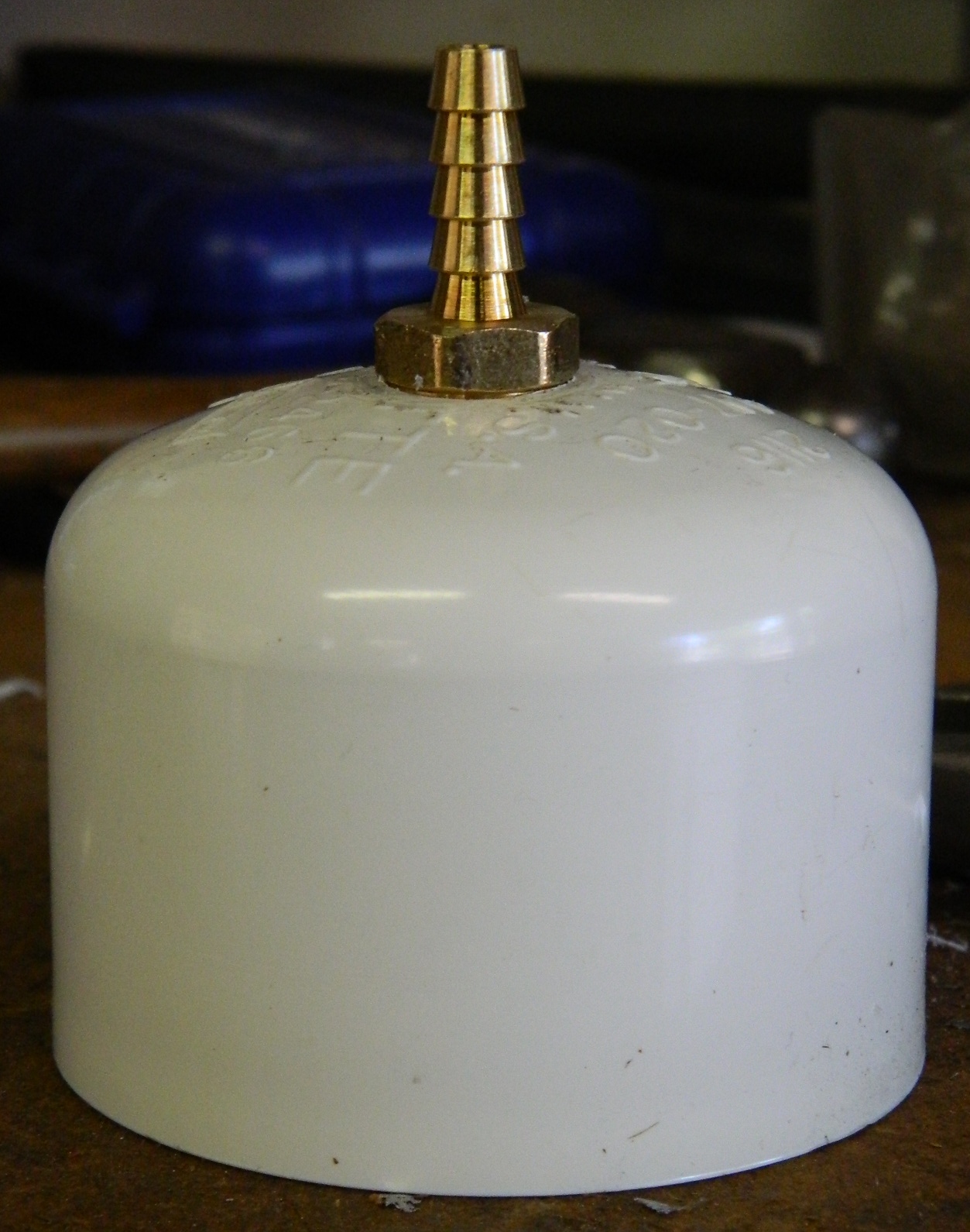
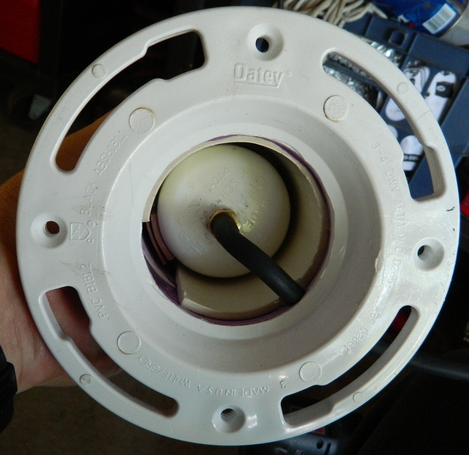
I started by drilling a 2″ end cap and seating a hose fitting to it:
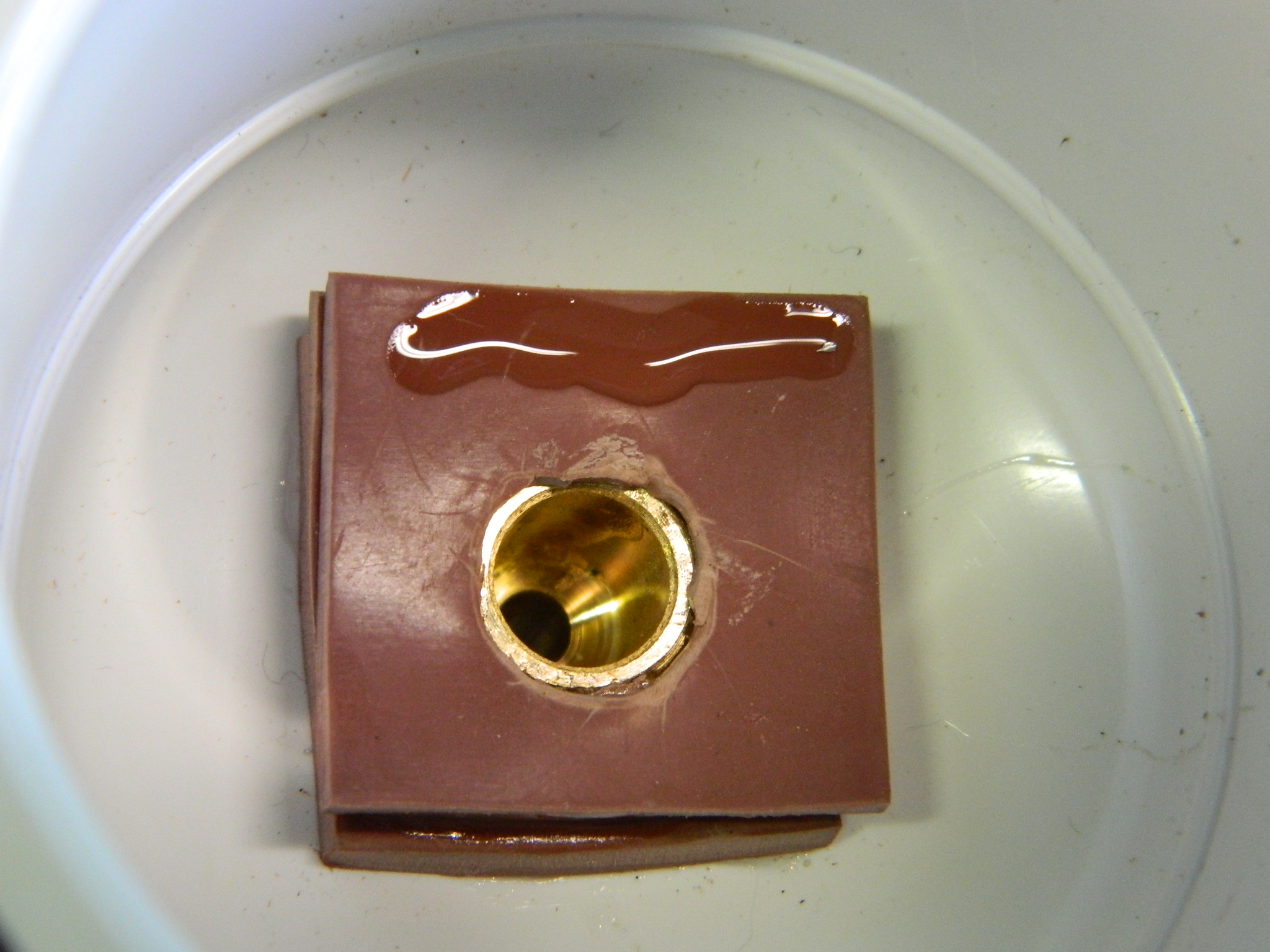
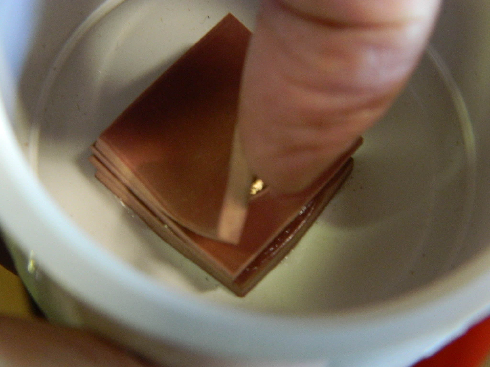
I made a flap valve using a few pieces of 1″x1″ 1/8″ rubber sheet by drilling out the centers. I used enough pieces so that the end of the brass fitting sits below the stack of rubber. Then I glued a 1″x1″ piece of 1/16″ rubber along one side only. This is the valve that closes under positive pressure to void the air pulled from the vacuum chamber to the outside:

I had a massive problem with the V1.0 pump. The body of the pump didn’t go all the way into the end cap with the valve and fitting. The first time I pushed the piston all the way in, the O-ring passed the end of the pipe…where is stuck. Solidly stuck. Which is to say, wouldn’t sodding come out. After two hours of very colorful invective (using some words in combinations that I hadn’t used in decades when I had to start an English motorcycle in the rain), I did manage to extract it (drilled the body of the piston crosswise, put a 1/2″ stainless steel rod through, braced the edge of the cap in a vise, and HAMMERED THE SNOT out of it with an engineer’s hammer, which finally extracted the rod, but required sufficient force to bend the stainless steel rod). I needed to figure out a way that this would never, ever, happen again…
I took a short section of the 1 ¼“ pipe and glued it into the 2″ cap around the flap valve. I cut the corners off the flap valve so there would be no interference, and superglued that ring in. I measured (a lot) to be certain that it was physically impossible for the O-ring to ever pass the end of the pump body again. EVER:

Then I drilled near the bottom of this cap/valve/fitting assembly and made the valve that closes under negative pressure to keep the outside air from getting in and then glued the completed part to the 2″x16″ PVC pipe that constitutes the pump body. Make certain the pipe bottoms into the cap all the way:


A 1 ¼“ cap now needs to have a groove cut into it to seat the O-ring. With the V1.0 pump I didn’t cut this groove deep enough and on the first pump the O-ring popped out. I suggest that you cut the groove as deep as half the diameter of the O-ring’s thickness. The reason why the first groove was so shallow was because I was concerned that I would cut too deeply and the end of the cap would come off. I figured out a way around that.
Cut an inch from the 1 ¼“ tubing. You’ll need to sand/file the outside surface of it so that it fits easily (yet snugly) all the way into the cap and glue it in. This will give you enough thickness to cut the groove deeply enough:

Then it’s a matter of cutting the groove. Be patient and check your depth relatively frequently. Now that you have backed up the inside of the area you’re cutting the groove into, you don’t have to worry about cutting too deeply, but it does take some time to cut this groove and I didn’t want to cut any further than I needed to. And since I have a lathe, I roughed in the groove using a cutter and then finished its round shape with a rat-tail file (I actually went deeper than the photo on the right shows):


With the O-ring in place, this is the part that seals the piston inside the body of the pump and every time you pull up on the piston, it pulls air out of the vacuum chamber creating a vacuum. The end cap is glued onto the 1 ¼“ pipe and forms the business-end of the piston:

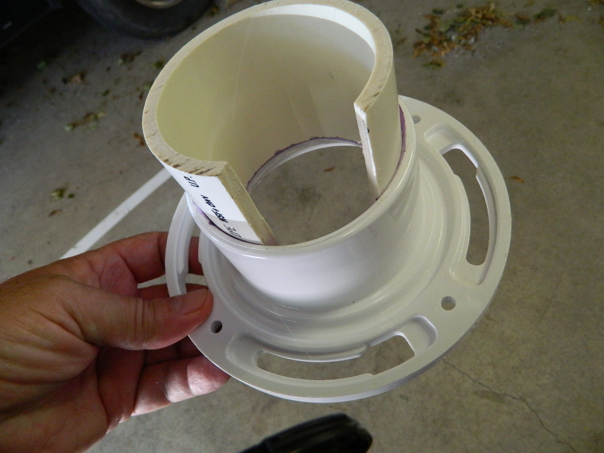
The base of the pump is assembled using the floor flange as the bottom. To that is added a 4″ length of 3″ pipe. But wait…there’s more. The 3″ piece of pipe needs a section cut out of it to allow the outer flap valve to work. Make sure your cut in the side of the 3″ is wide enough to accommodate the width of the outer flap valve. Once you’ve made that cut, the pipe will contract slightly. Reverse the piece you cut out and stuff it back into the opening. This will keep the section of pipe at the proper diameter and allow it to bond with the floor flange when you glue it (you’ll see what I had to do in the Vacuum Chamber section when I didn’t get this step quite correct).
With the reversed piece in place, the 3″ pipe gets glued into the floor flange. Let this sit for at least an hour (I let it sit for two) so that the parts bond solidly. You’re going to be standing on this and yanking upward firmly and often:

Reducers have a lip molded inside to keep the smaller pipe from slipping through the reducer. Since you’ll want the smaller pipe to slip through the reducer, that lip needs to be ground away. (If you have a Dremel or the like, that cuts down on the time this step takes.) Once you have that lip gone, you’ll need to open the inside diameter of the 2″ area of the reducer so that the body of the pump, a 2″ pipe, will slide through there. You want this to be snug but not immovable:

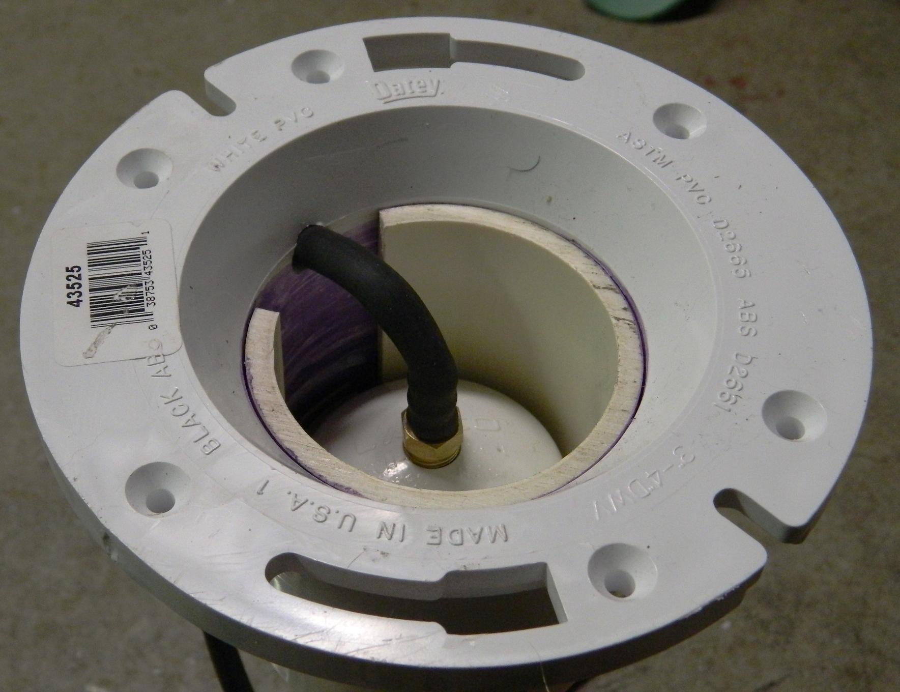
Snap the cut piece out of the pipe and then glue the modified reducer over it and drill a hole large enough for the vacuum tubing to fit through without pinching:

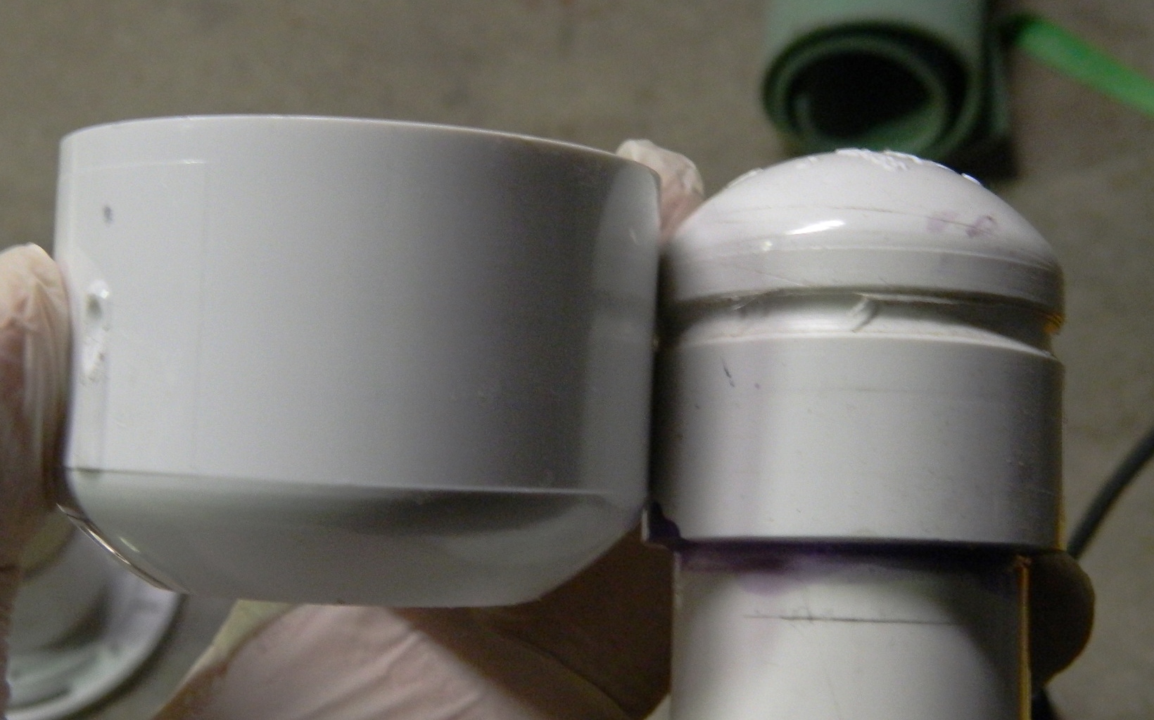
Now the body of the pump is fed up through the bottom of the base and glued, pushing the body in until the lip of the cap stops at the bottom edge of the reducer. Make sure that the flap valve and the cutout section of 3″ pipe align, otherwise the flap valve won’t work:
Time to insert the piston into the body. With the O-ring in place, THIS IS A TIGHT DAMNED FIT! The only way I was able to get the piston to go in was to chamfer the top of the body of the pump. I used a half-round file and sandpaper until the outer edge was about half the original thickness:

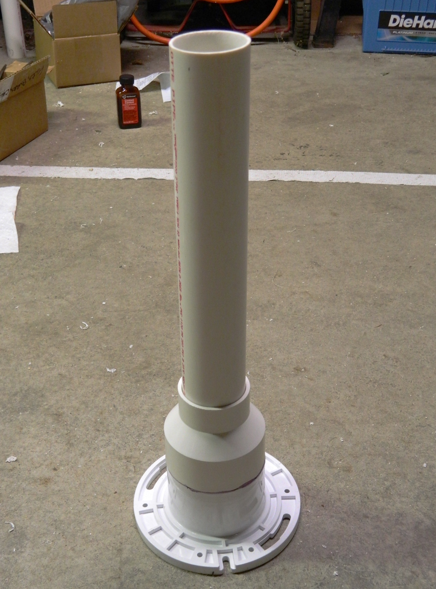
By now you should be here:
Feed the vacuum tubing through the hole and attach it to the fitting. Subsequent use of this pump showed me that the tubing doesn’t fit quite tightly enough so I used a cable tie pulled TIGHT to seal the tubing to the fitting:
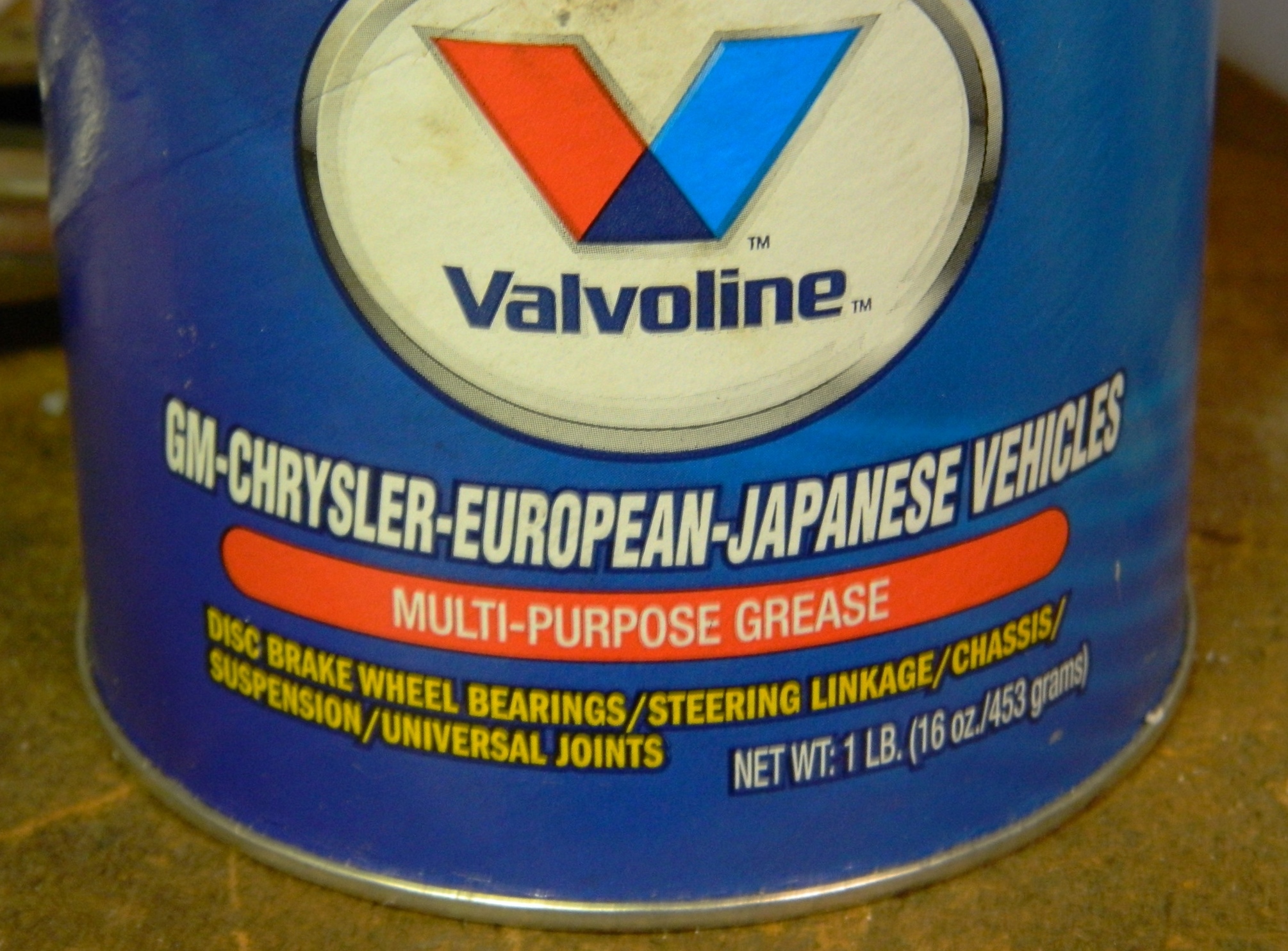
Time to install the piston. Use grease to help the seal, extend the life of the O-ring, and to get the TIGHT DAMNED FIT to…well…fit:


The retainer is needed to keep the piston in the pump because you will be pumping vigorously to build up vacuum. The video shows a reducer that I wasn’t able to locate locally. My way around that was to take the other 2″ cap, chuck it into my lathe, and cut enough away so that the body of the piston would slide freely within it (you can also mark the hole, start the hole with a bit, and either file or use a Dremel to get the diameter to where you want it):


And because I clearly remember how much sodding, freaking, GOD DAMNED FUN it was when the O-ring slipped past the body of the pump, I made sure that the O-ring would not slip past the body of the pump at the top, either:
So, with the piston inside the pump body, slide your reducer over the body of the piston. Again, because these fittings fit TIGHTLY, I sanded the inside of the retainer (a lot) so it would fit easily over the end of the pump body and come off just as easily (eventually the O-ring will wear out and need replacing). To be certain that the O-ring would stay inside the pump body, I held the retainer in place with my hand and pulled (gently) up until the piston would go no further. Satisfied that all worked as intended, I glued the last 1 ¼“ cap in place on the end of the piston. I used self-tapping sheet metal screws to hold the retainer in place securely yet not intrude into the pump body and interfere with the piston:

All that remains now is to drill out the top of the piston and insert the 10″ long, 3/4″ diameter, dowel to use as my handle:
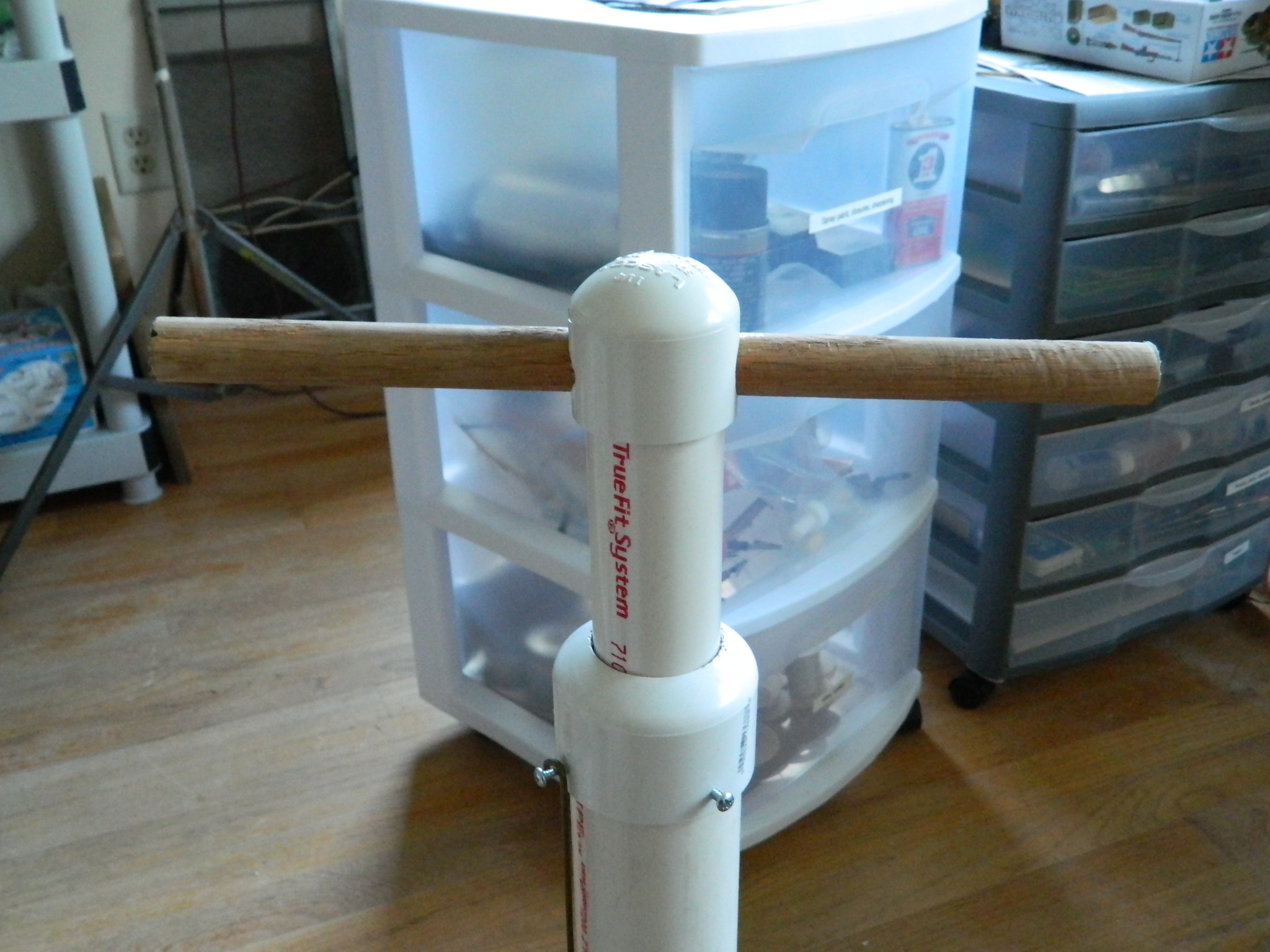
Next step, build a vacuum chamber!
Subsequent Edit:
In using the chamber, I found a couple of major problems to address.
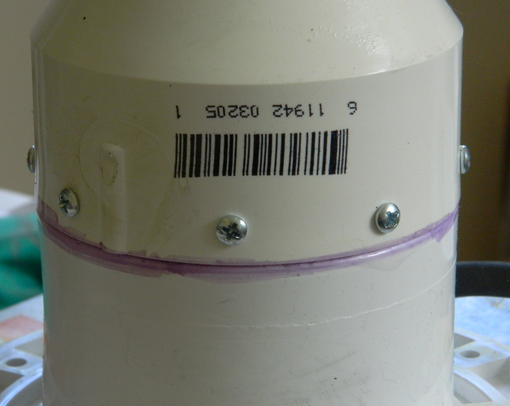
During the construction of the pump, I wasn’t entirely sure that the 3″ section of pipe that connected the flange to the reducer had bonded properly and it turned on it hadn’t. Though the 3″ section bonded very well to the flange, only half of it bonded to the reducer and that snapped free. It doesn’t affect the pump’s ability to create suction, but it does compromise its strength. So I used screws to attach the loose section of pipe to the reducer:
I’ve used the pump a number of times since its construction (and fix) and it’s holding up well.
Another thing I noticed during its first use is that the vacuum bleeds off over time. It takes just under two minutes to go from about 27″ of vacuum to 0″. In using it, I discovered that 15″ of vacuum is about the minimum I want to work with and that equates to a lot of pumping! I diddled about a bit. I added cable ties to seal the hose to the fittings more tightly and that decreased the vacuum bleed off a little. I still don’t know why I did this, but at one point I held the piston up (because vacuum with this pump is created on the up-stroke; it looks like a plastic bicycle pump but operates in the reverse in all ways). I noticed that this slowed the vacuum bleed off substantially. So I drilled a hole across the body of the piston and use a coat hanger to hold the pump up:

Okay…it does work. The emphasis should be on WORK. It takes A LOT of work to generate about 23-25″ of vacuum (the more vacuum generated, the better degassing works). Yes…that’s enough vacuum but it’s TOO MUCH WORK to keep the vacuum.
I needed a better pump.

[…] Making the Pump […]
LikeLike