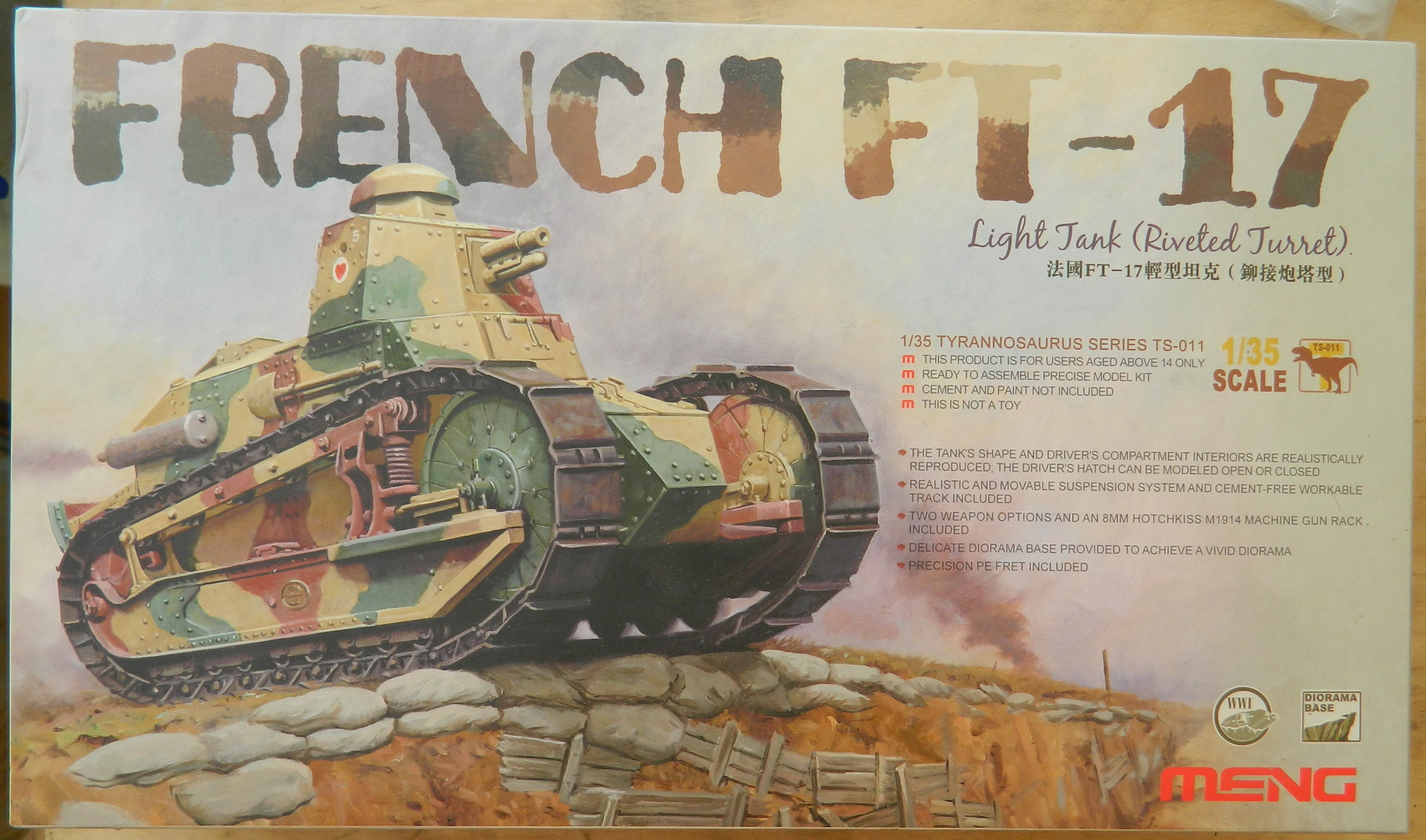
Once upon a not-so-long-ago time, I had a notion to do a model of each tank that the US Army deployed. (I may still have that notion…check back and see if I live long enough.) (At 70, that’s a factor.) The first tank deployed was the Renault FT-17, not the M2 or M3 Light Tanks or Combat Cars.
Meng makes two kits of the FT-17 in 1/35 scale. #TS-M008 (has an engine for the engine compartment) and #TS-011 (no engine). Since I didn’t want to model it with the engine compartment open, I’m building the TS-011 kit.
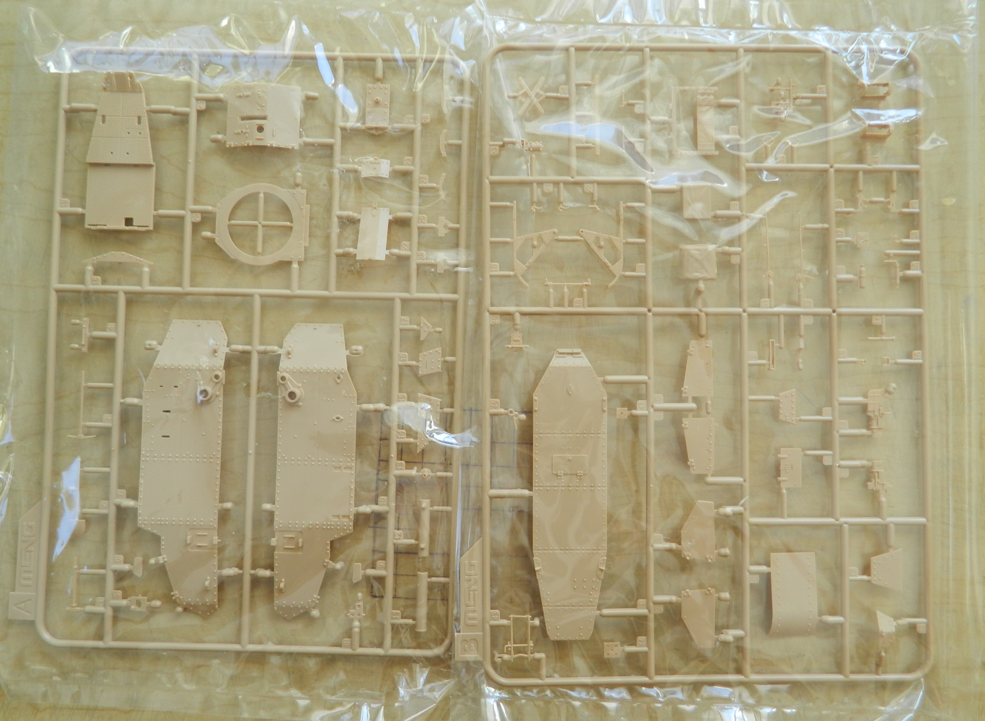
Here’s what the kit offers:

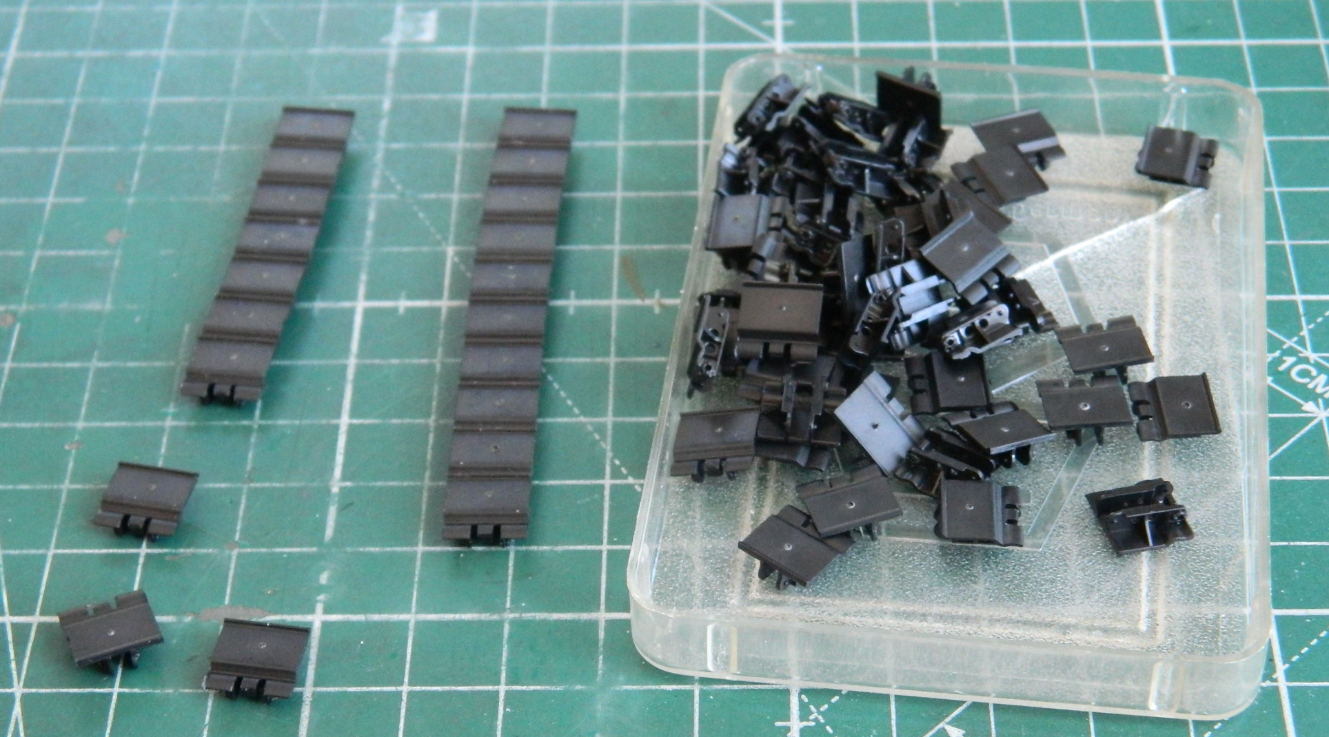
Since this has individual track links, I started by assembling them. I was going to do that with my new traditional method, assemble track links while having my tea and waiting for my brain to start functioning. They were so easy to assemble that rather than do ten a day, the second day I just finished them all; the instructions state there’s only 32 links per side. They were cleanly molded with only a few instances of flash. There is a nipple in the center of each link that needed to be sanded flat and a circular depression around the nipple that needed to be filled (the white dots you’ll see in the photo):
If I have a choice, I prefer to start with the most annoying and/or difficult tasks first while my enthusiasm for a given project is at its greatest. In this case, perusal of the instructions indicated that the suspension was going to be that job this time. LOTS of little wheels and other metal bits:
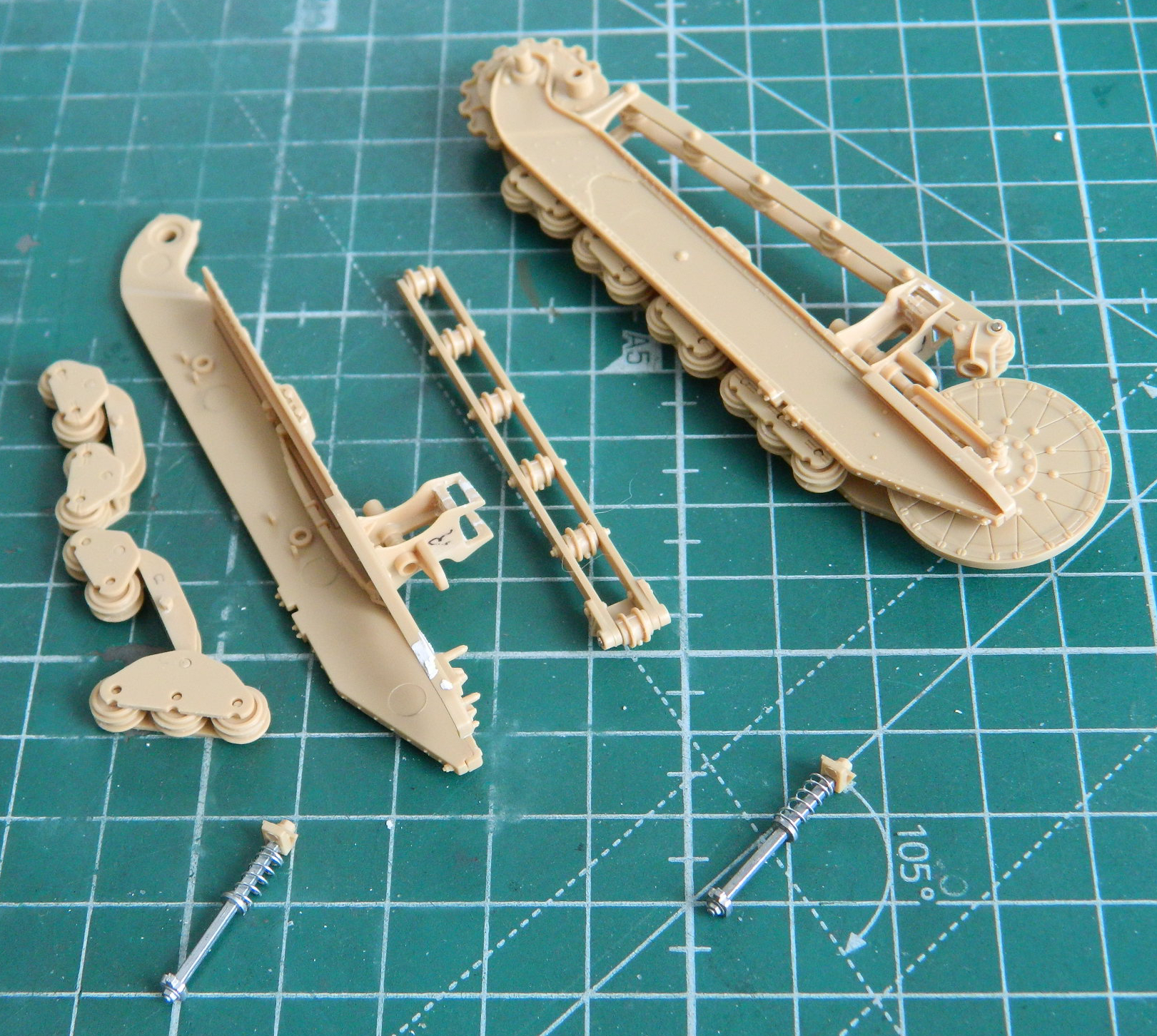
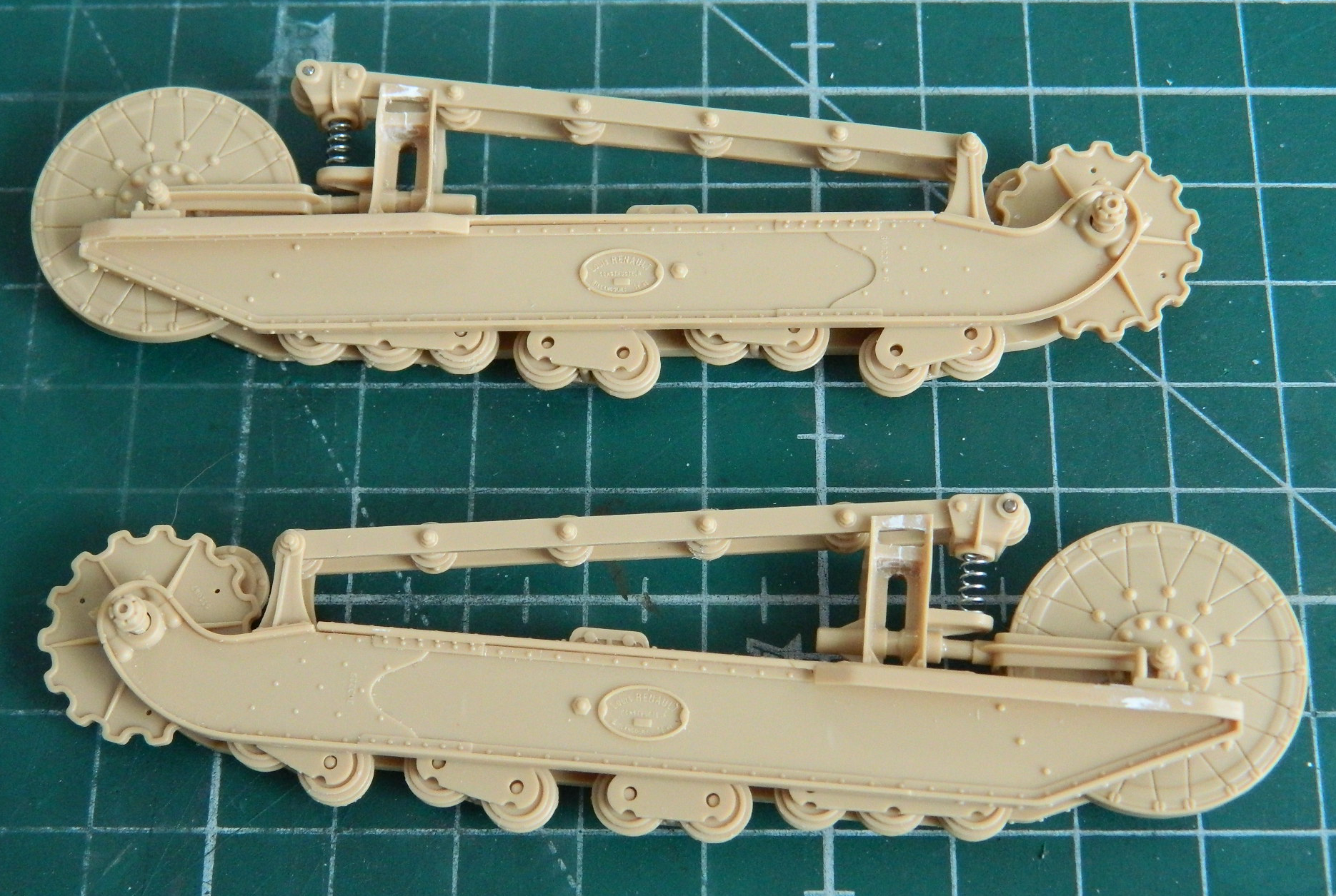
Painting them is going to be so interesting.
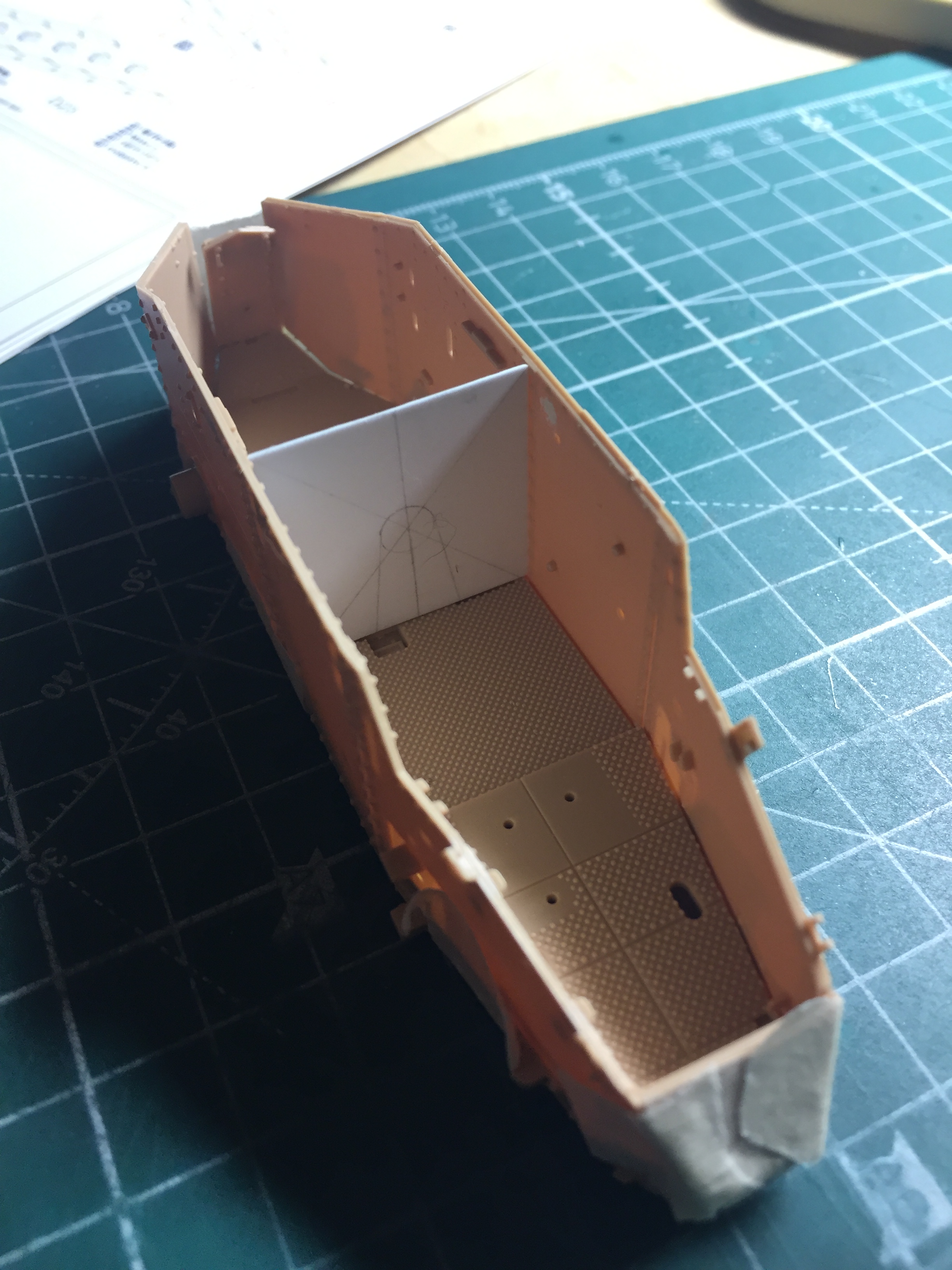
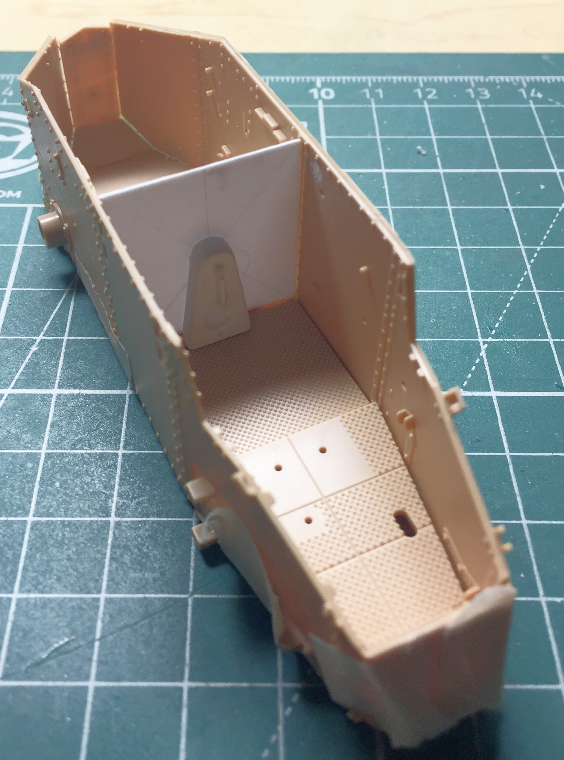
When Meng decided to release a FT-17 kit without its engine, evidently they didn’t include the frets that had the engine parts. Logical. Unfortunately, it seems as if in so doing, Meng didn’t provide significant interior details, either. There’s no bulkhead between the crew compartment and the engine compartment. There are no ammunition racks on one side of the commander/gunner position. There are also no (what appear to me to be) mine racks on the other side.
I actually considered buying another kit, the TS-008 kit with engine and missing interior parts. While thrashing about on the ‘Net, I found a firm in Australia that makes a PE update set that happens to include the ammunition and mine racks. Of course, there’s no mines OR ammunition included with the set. I’m guessing that I’ll have more than a few days to decide if I want to add the ammo and mines, and if so, just how the intercourse I’m going to. But in the meantime, I decided to make the bulkhead. That started with taping the sides of the hull and floor together so that I can fit .020″ (.508mm) styrene to make the basic bulkhead:
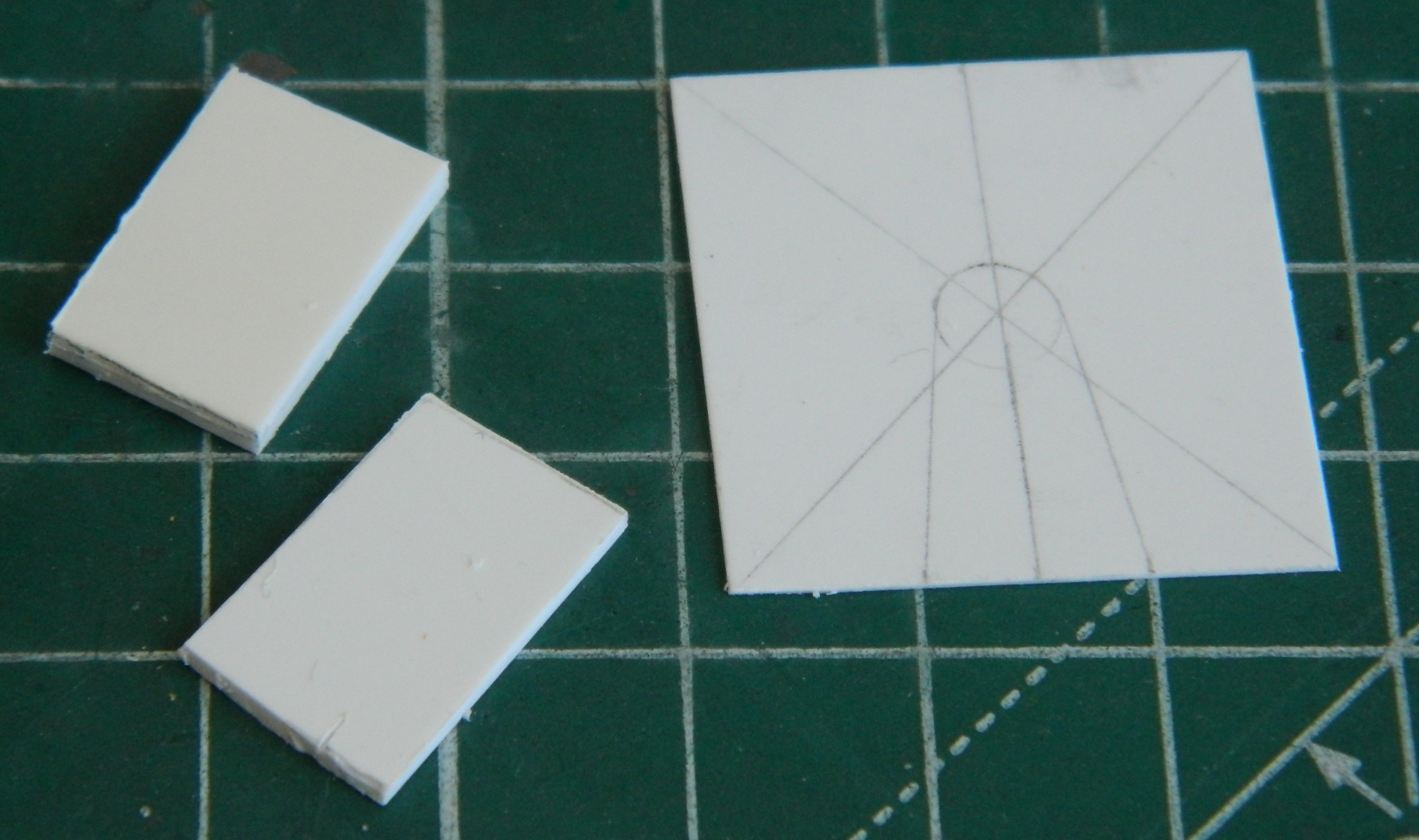
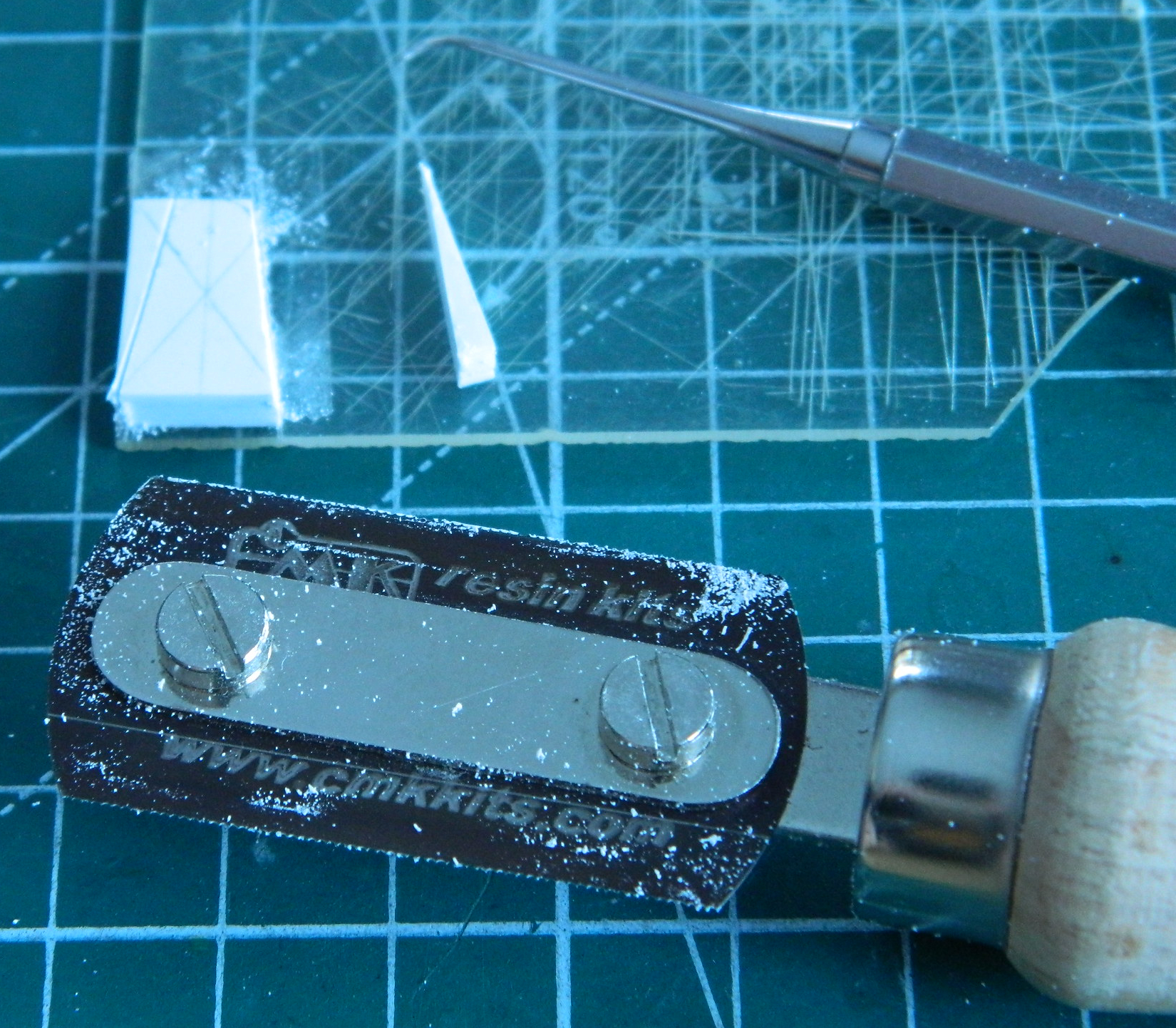
There is a protrusion on the bulkhead with details. One of the details is the crank used to start the engine. The other detail I have no idea what it is and I haven’t found any reference photos that will tell me (my suspicion is that it’s part of the transmission), but since it’s there and visible, I make the attempt to include it. First, let’s start with the bulge itself. After laying out the design on the .020″ (.508mm) that will become the bulkhead, I used .080″ (2.032mm) and .040″ (1.016mm) scrap styrene and bonded them together:
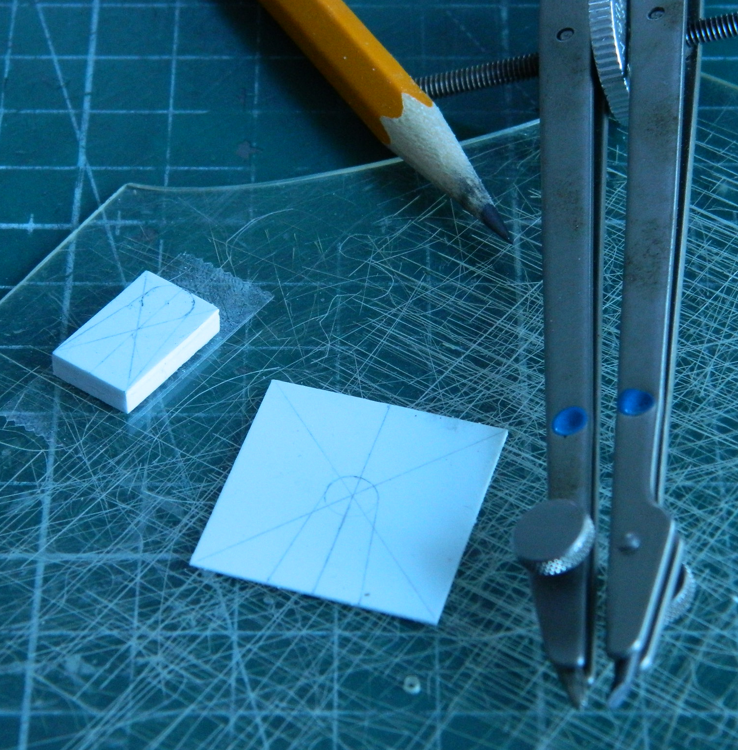
After spending the night clamped into a vise, I squared all the sides and then transferred the measurements on the bulkhead to the laminated plastic and started cutting (double-sided tape applied to a welding mask shield enable me to cut just the plastic and not my precious, if scarred, fingertips):
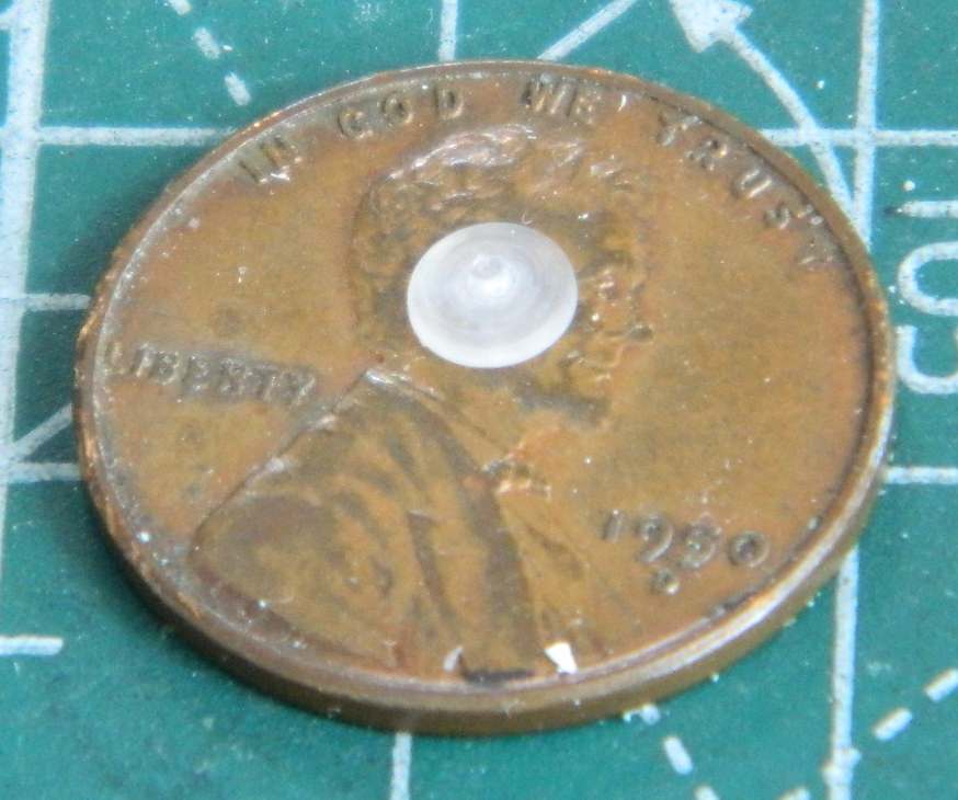
The starting crank was made from various scrap bits of styrene (because who throws anything out?!) and then drilled the depression for the Mystery Part using a 3/16″ (4.76mm) bit, then checked it all for fit and alignment:
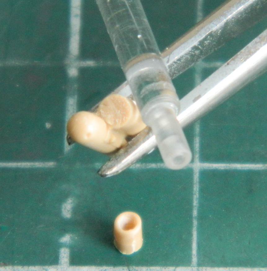
My first attempt to make the Mystery Part was to use 3/16″ (4.76mm) styrene tube, fill it with Apoxie Sculpt epoxy putty, and then I would turn the end down on the lathe once the putty cured (an overnight process):
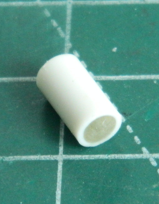
Almost a nice idea but the putty didn’t adhere to the inside of the styrene tube. The next attempt used clear acrylic rod in the lathe and that worked well enough:
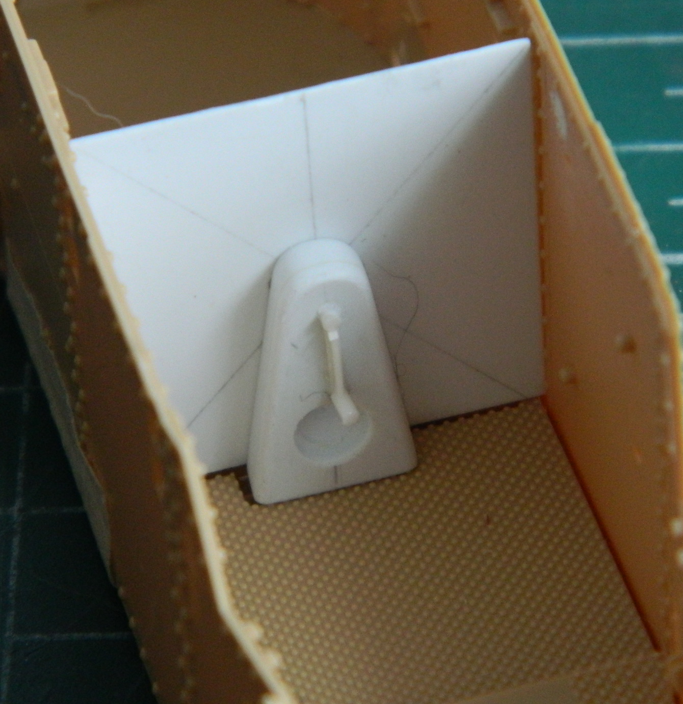
Test fitting it does what I wanted it to do (and here’s hoping what I wanted it to do was correct) so I superglued it into place:

Dry-fitting again showed me that it’s what I wanted (with the same caveat as before):
Since I’m waiting for parts to come from Australia, and I don’t expect them to arrive quickly, I started working on other things. That started with the gun assembly, assembling parts and adding putty where needed:

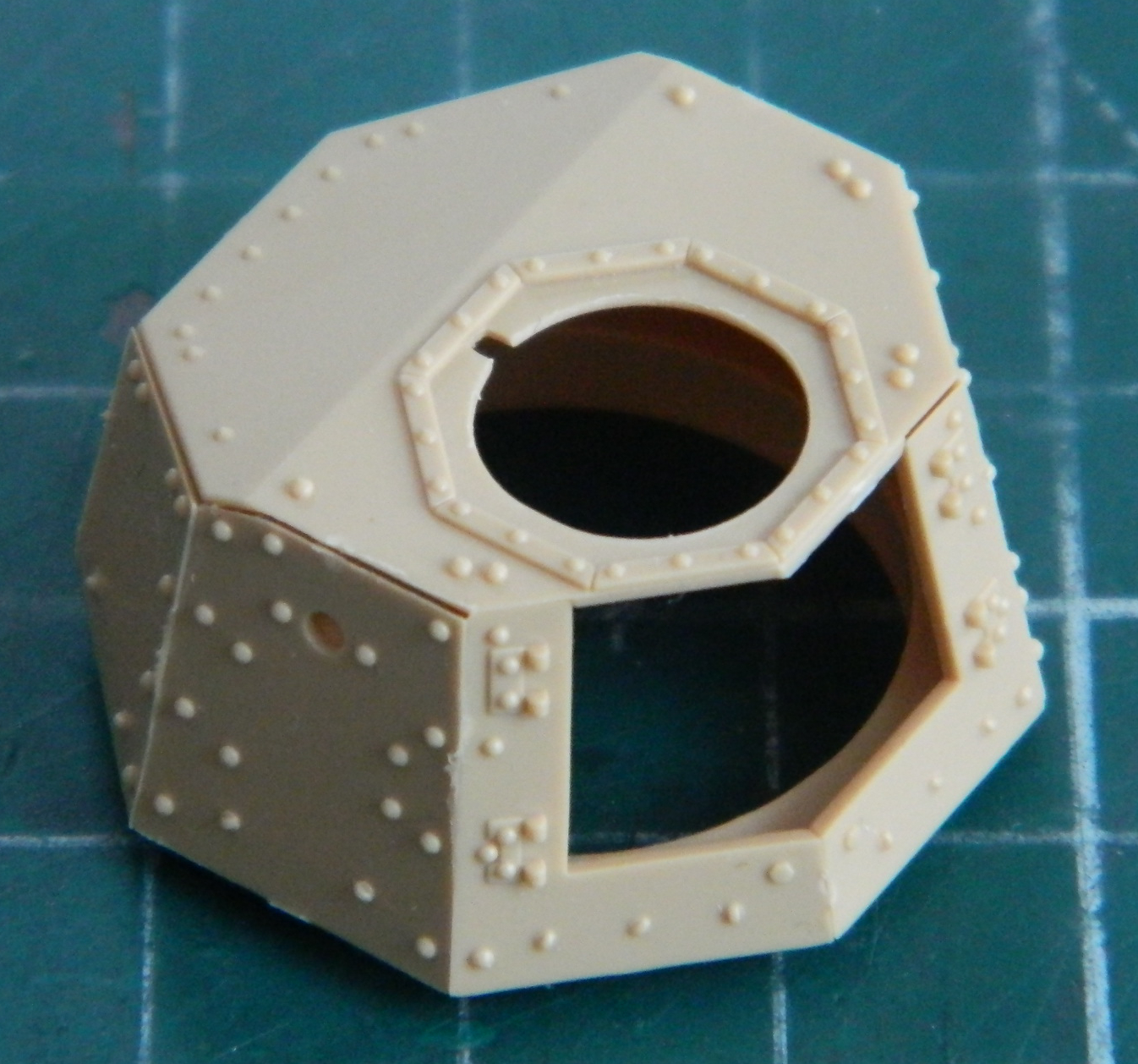
While the putty cured, I started assembling the turret:
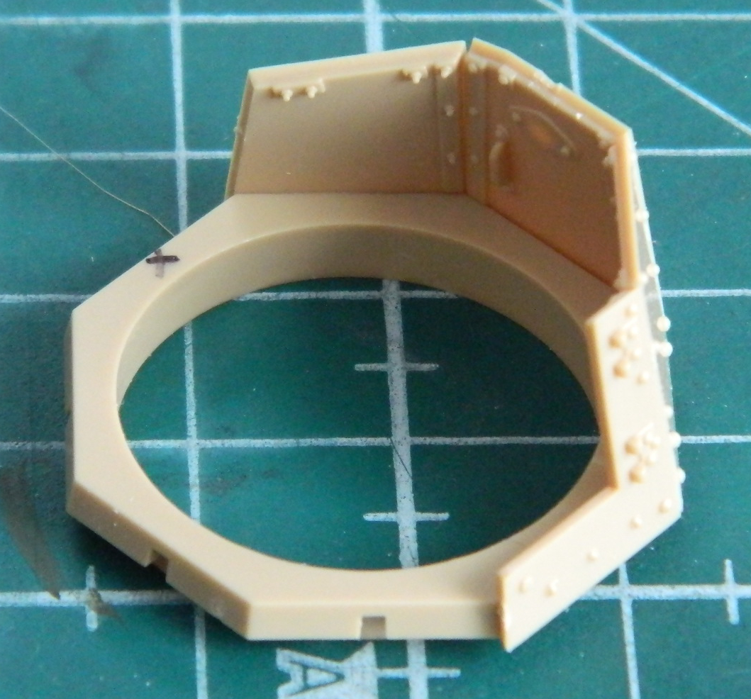
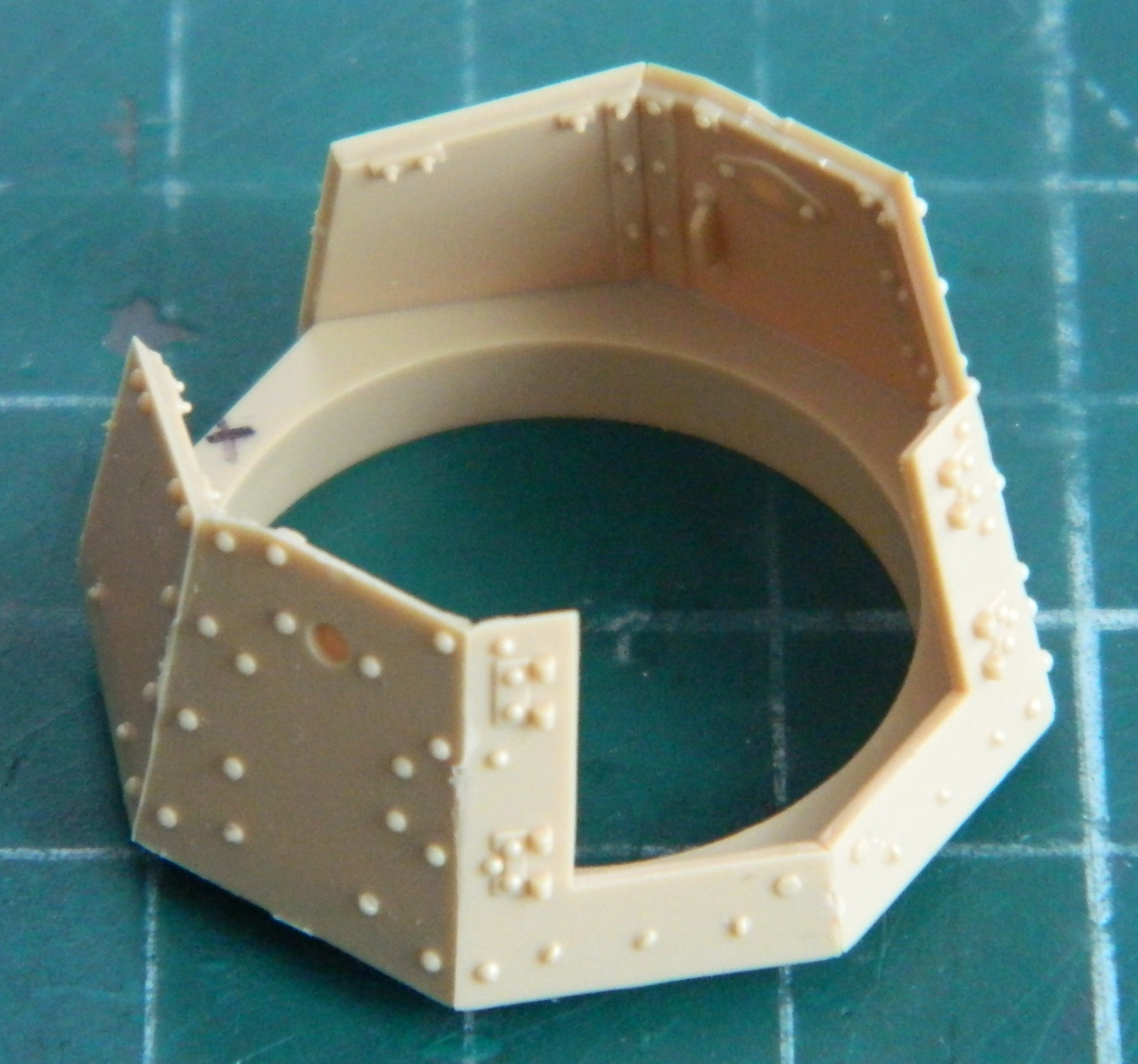
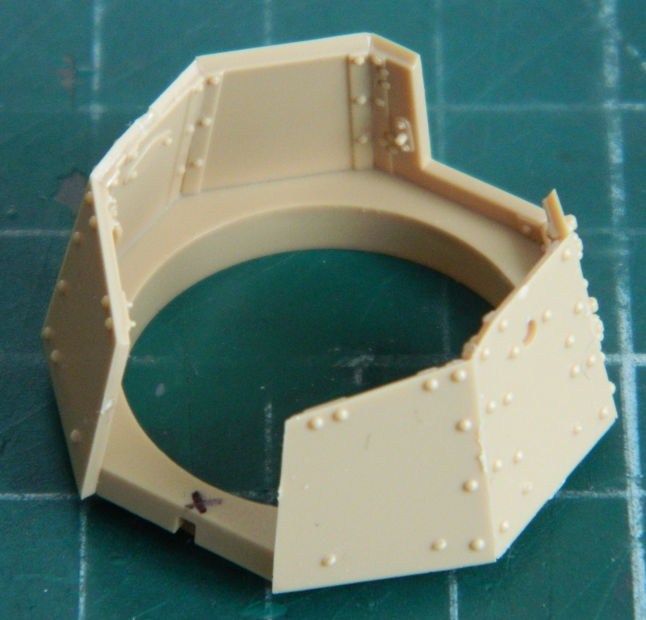
There were some small gaps between the panels that were puttied, then I test fit the top and realized that I’ll be adding more putty when that gets added later after painting the interior:

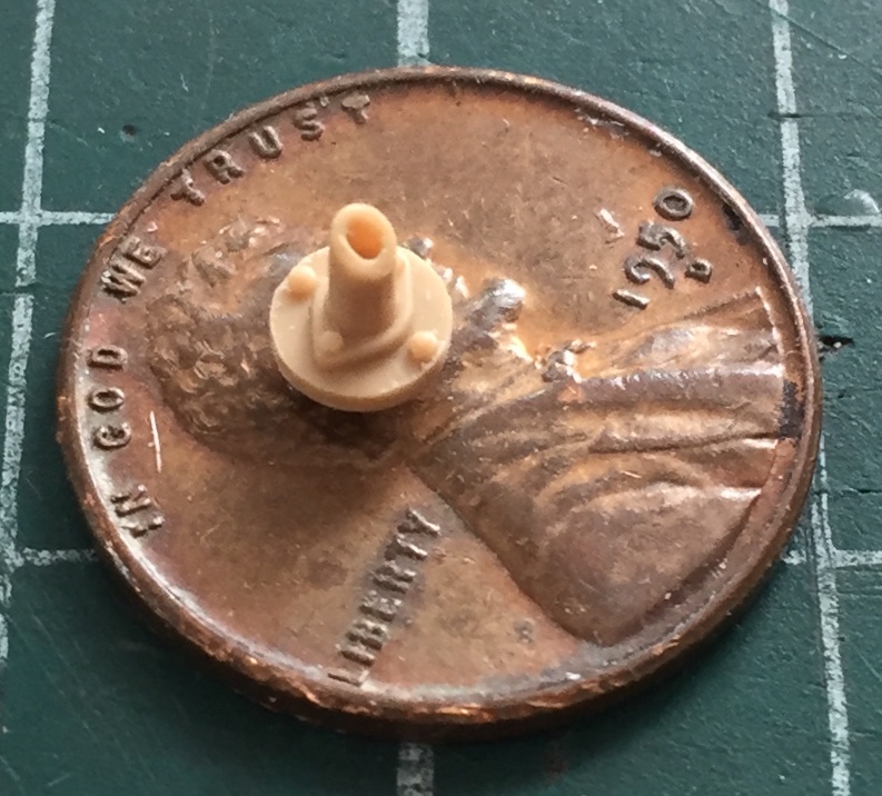
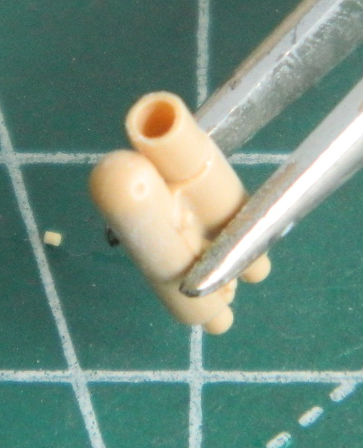
I wanted to assemble the muffler next. Before I did that, I decided to thin the exhaust tip to something a little more scale:

I assembled most of the upper hull. The open slot in front of the rectangular part sticking up wasn’t assembled because another part that goes there is supplied on the PE fret that’s coming from the other side of the planet. I want to see which one looks better before committing to it:

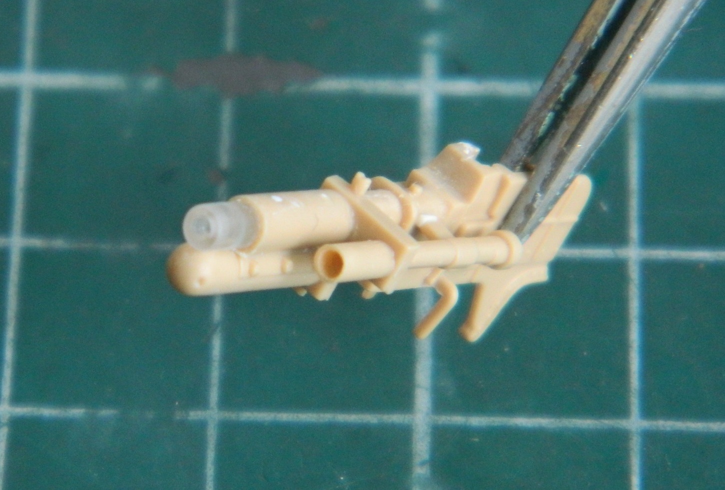
This is where liking something sort of slopped over onto something it should not have. I liked how the exhaust tip turned out so much that I decided that I would treat the bore of the cannon the same…without checking references before I did so:
Sure…it looks good. But once I finally checked references, that good look is also wrong. It’s a thick-barreled cannon. ::sighs:: Okay, so I filled it with styrene rod:
Then I drilled the bore back to where I should have left it. Well, almost, anyway. Sodding thing was off center. Filled the hole, glued more rod, and it was off center in the other direction. Of course the THIRD attempt was off in another direction and the small, frail, piece of plastic that should have been left alone to begin with told me that it was no longer interested in playing my stupid game. Fine. So I cut it off and made a new one on the lathe from acrylic rod:
At this point the gun barrel looks better than it has since before I “improved” it:
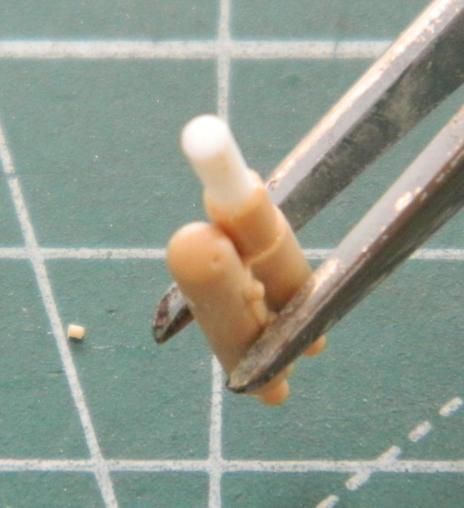
Belaboring the point, the FT-17 was a very small tank. It was so small that to traverse the turret, there were two leather handles the commander/gunner grabbed and then he pushed with his feet to rotate the turret. Instead of fins, there should be leather straps instead. I carved away what had been molded on and replaced both of them (one on each side of the turret) with lead foil (it’s the yellow part left of upper center in the photo):
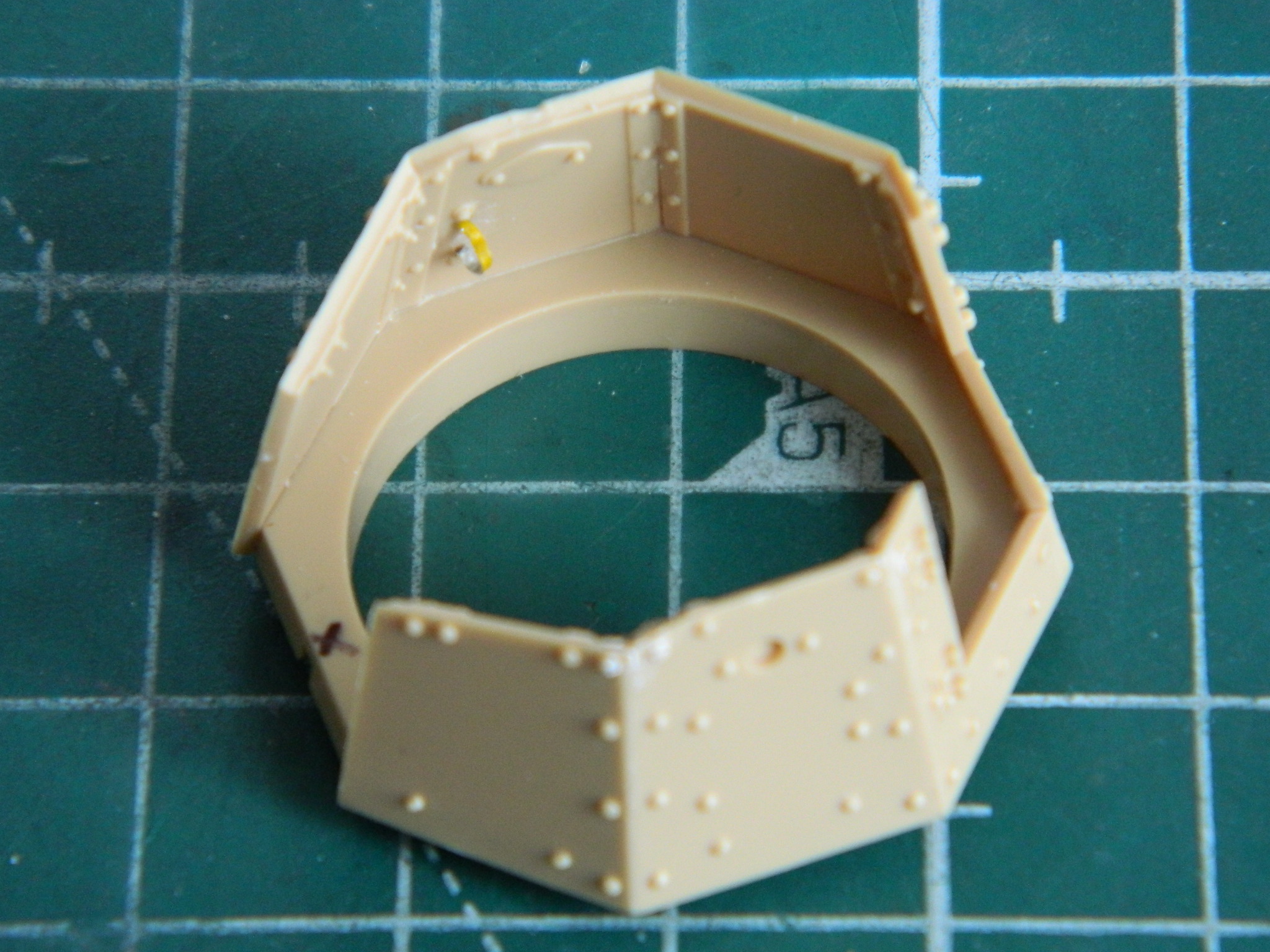
I added the “mushroom cap” hatch to the turret top and removed molded-on location marks on the inside faces of the turret’s doors to add more lead foil “straps” later:

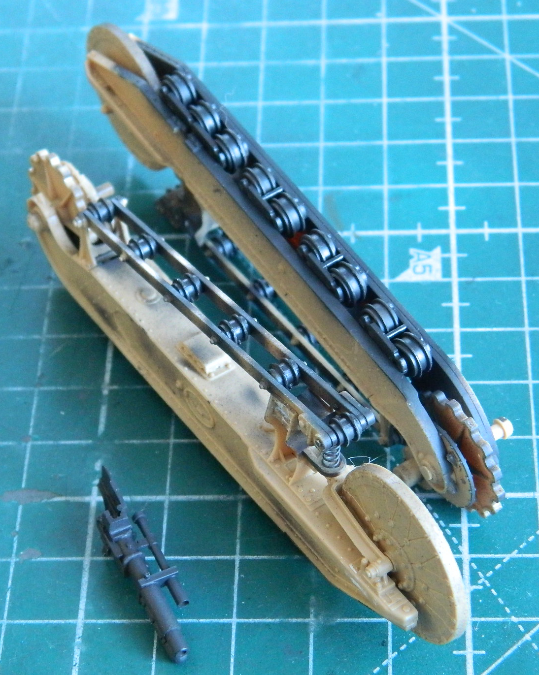
I mixed a batch of my home-brewed “gunmetal” paint (5 parts Tamiya X-18 Semi Gloss Black and 4 parts Tamiya XF-20 Medium Gray) and painted the gun and all the suspension wheels:
It’s likely I’ll probably diddle around some more while I’m waiting for the PE parts to arrive, but essentially, the build is on hold until they arrive.
