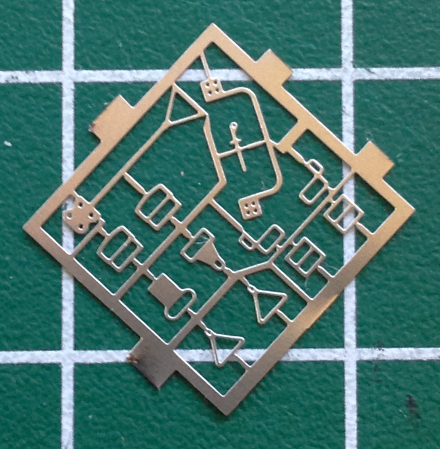
Once upon a time, there was a California-based company called Model Technologies that produced some very fine photo-etched details. I was fortunate enough to pick up a few of their items way back when because they have since gone out of business and if anyone has picked up their line, I can’t find them. What made MT’s stuff so nice (other than the fact that it was a damned good product) was that they used stainless steel for many of their products. This is a good thing because I’m using MT’s seat belt buckle set and it’s VERY SMALL. Brass of this size would be more fragile than useful. Stainless steel is strong enough to survive the manipulations required of them:
And from my initial attempt to convert a P-51B to an Allison Mustang, I had a seat cushion I’d made from a sheet of .060 styrene. I checked its fit and though slightly smaller than I would make today, I decided it was certainly close enough so I painted it and glued it in place:

With the MT buckles, the harnesses are replicated using paper that is then threaded through the buckles the way the actual harness was threaded. The first paper I tried was paper towels from a public restroom:
One of the things I liked about this paper was it was already about the color I wanted. But I discovered that once soaked in dilute white glue, the physical properties of the paper itself was too loose to survive any manipulation, coming apart instead:
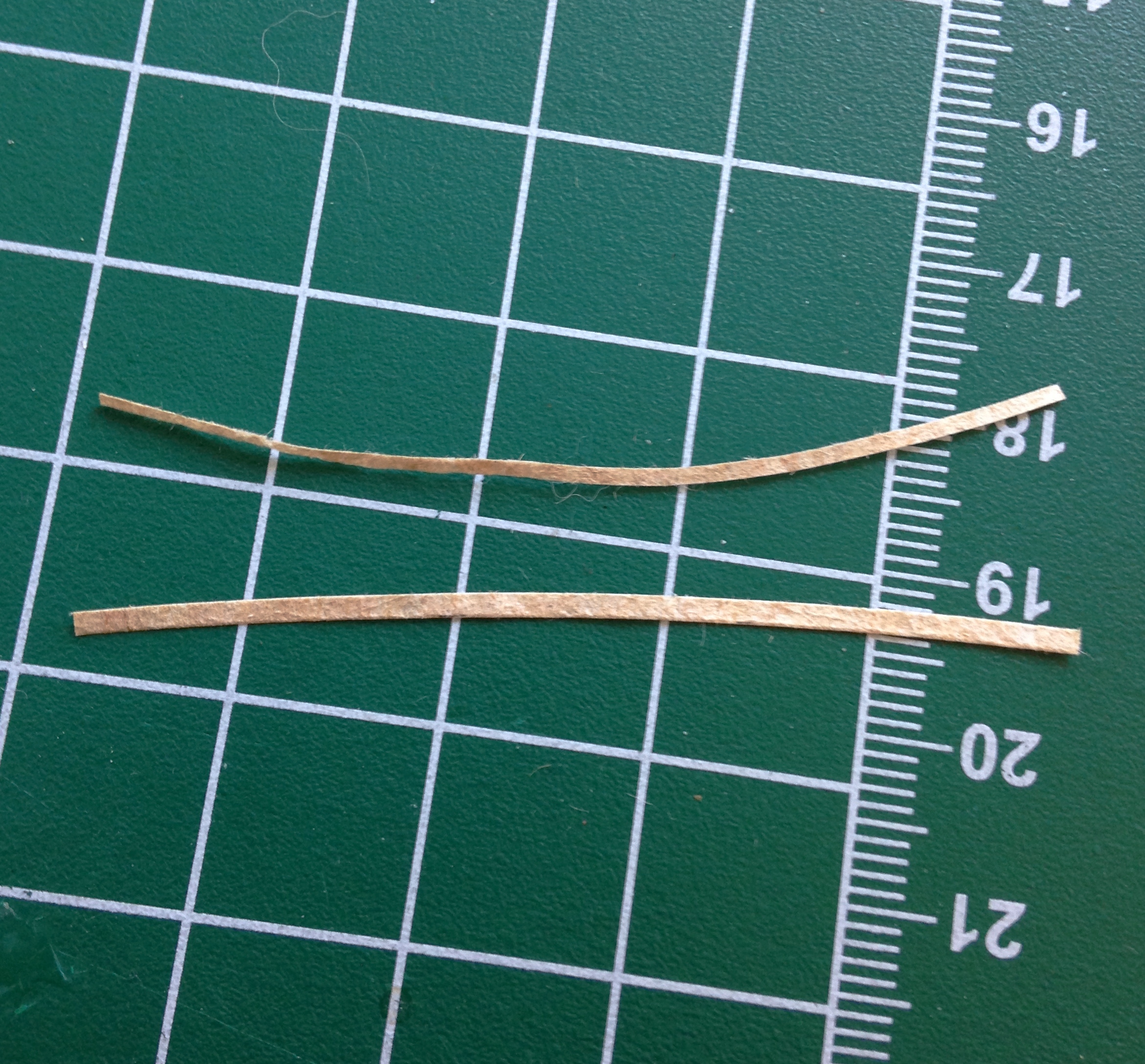
What I ended up using was the paper from a white Post-It pad (though I’d also considered using the paper of a dollar bill because of its high linen content):
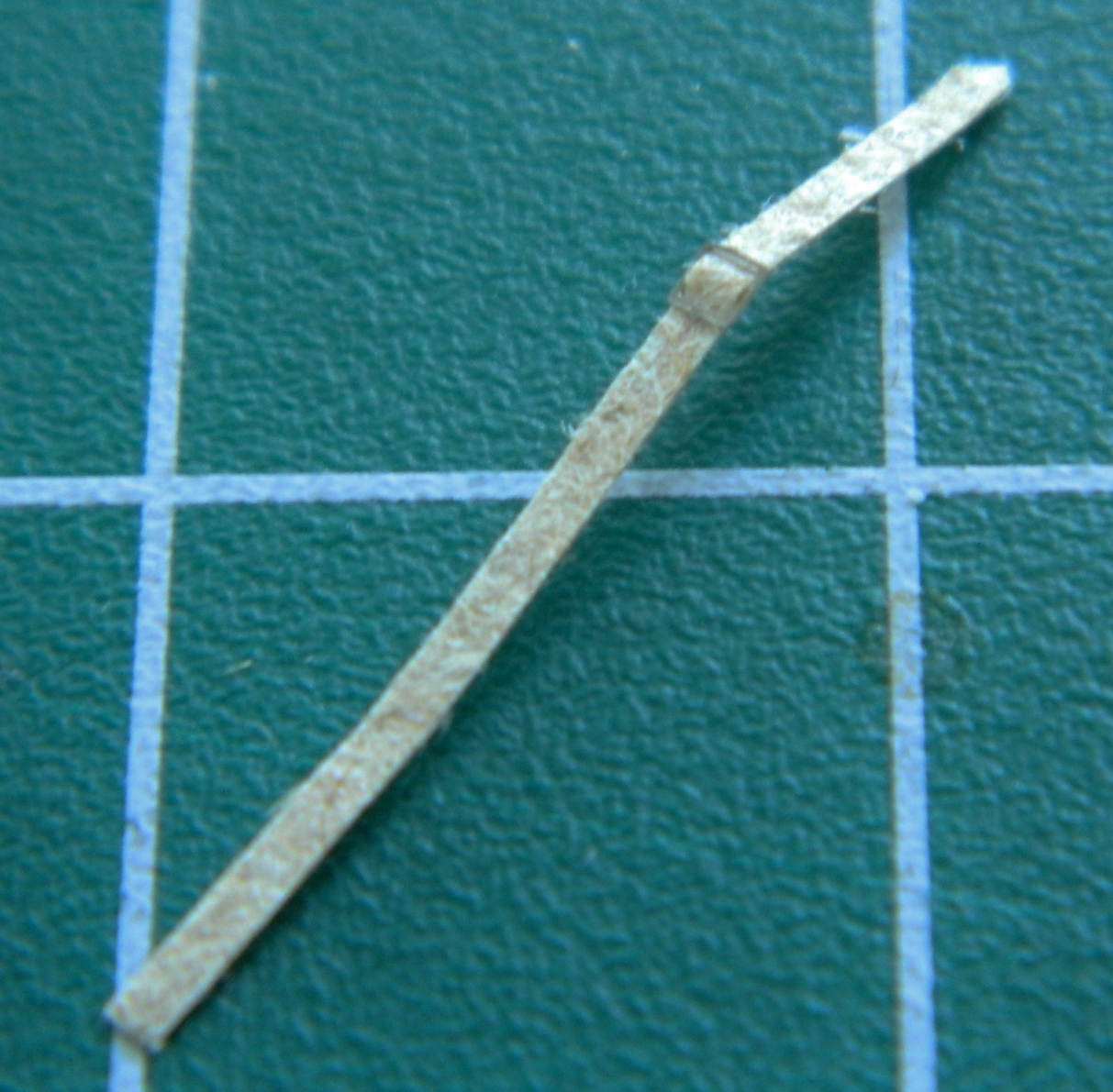
Pleased with how it turned out (and equally pleased it didn’t come apart once soaked with dilute white glue!), I went on to the FIDDLY task of threading all the straps through buckles and getting them ready to paint. And speaking of “small,” the latching mechanism on the end of one of the lap straps is not only FREAKIN’ TINY, the loop has to be turned ninety degrees and the tail curved and THEN glued on:


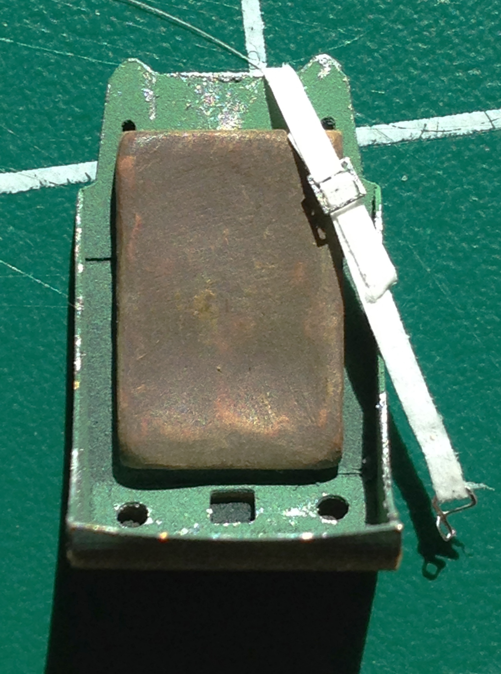
Once done with the tedium of the straps, they were all painted and glued into position:
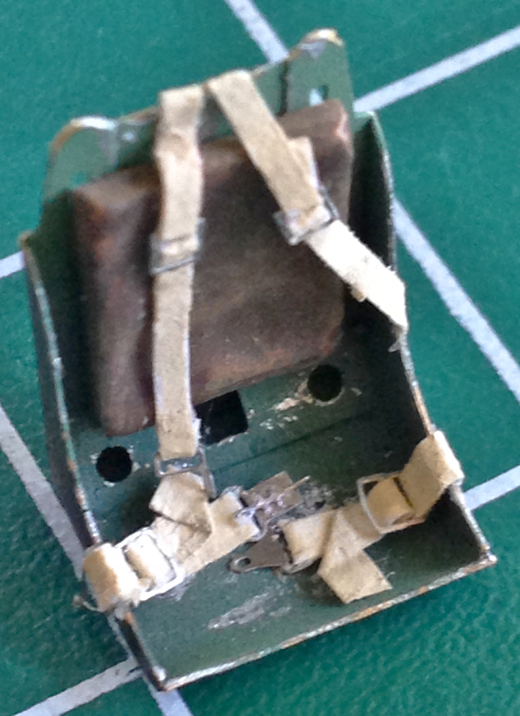
This is an illustration about why I go through all this trouble. In the next photo, the seat on the left is the kit-supplied part, the center is the seat that came with the resin detail set, and then obviously the one I’m using:

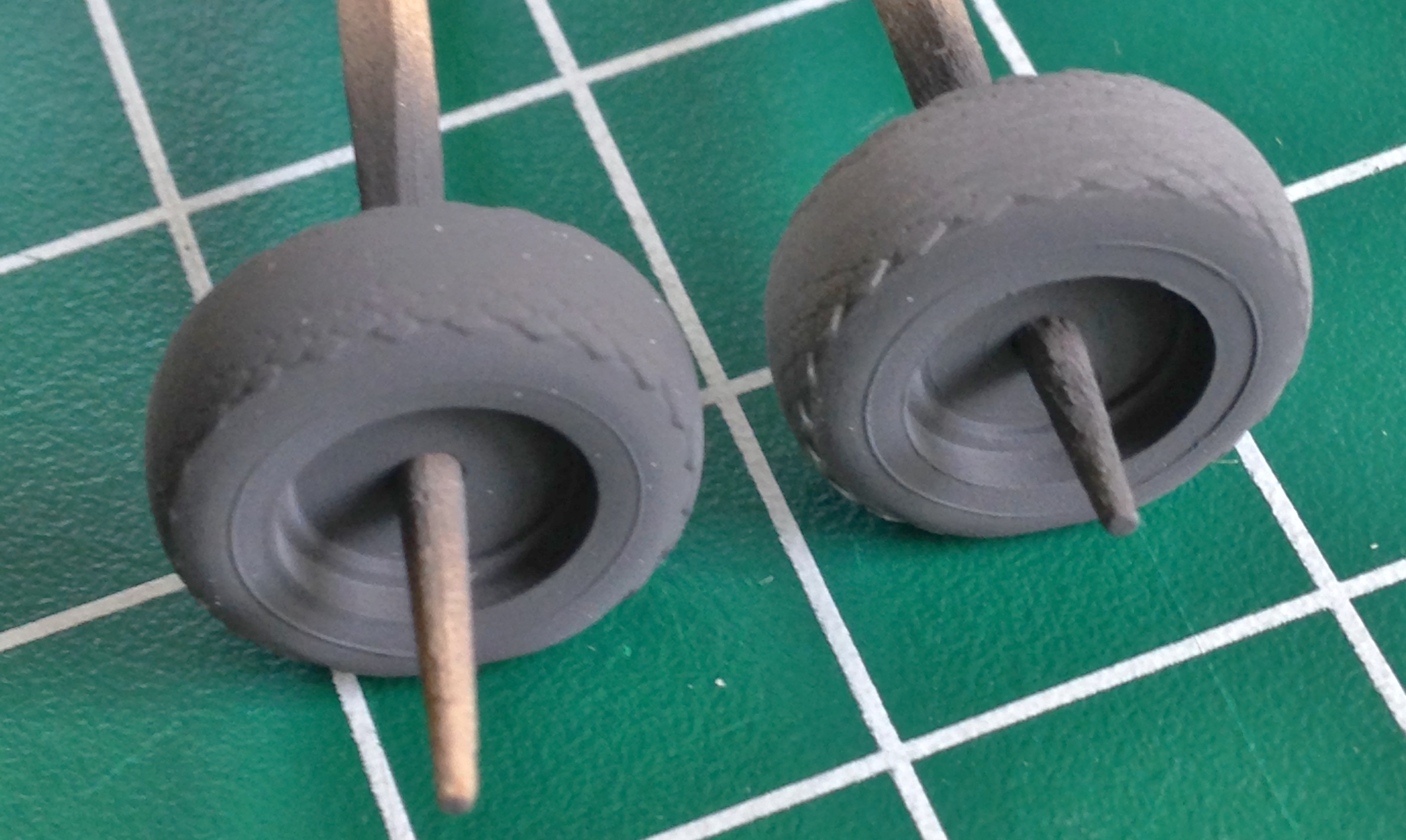
While the acrylic paint cured a bit, I turned my attention to the tail wheel assembly. The first thing I noticed is that this assembly is molded as one piece…and it’s obviously so. So before I can use it/them, I wanted to separate the wheel and tire from the strut:

I used the tail wheel part from my sacrificial kit as well. From one part I cut the tire away and re-sculpted the strut to the proper L-shape, and from the other part I cut away the strut to end up with just the tire:

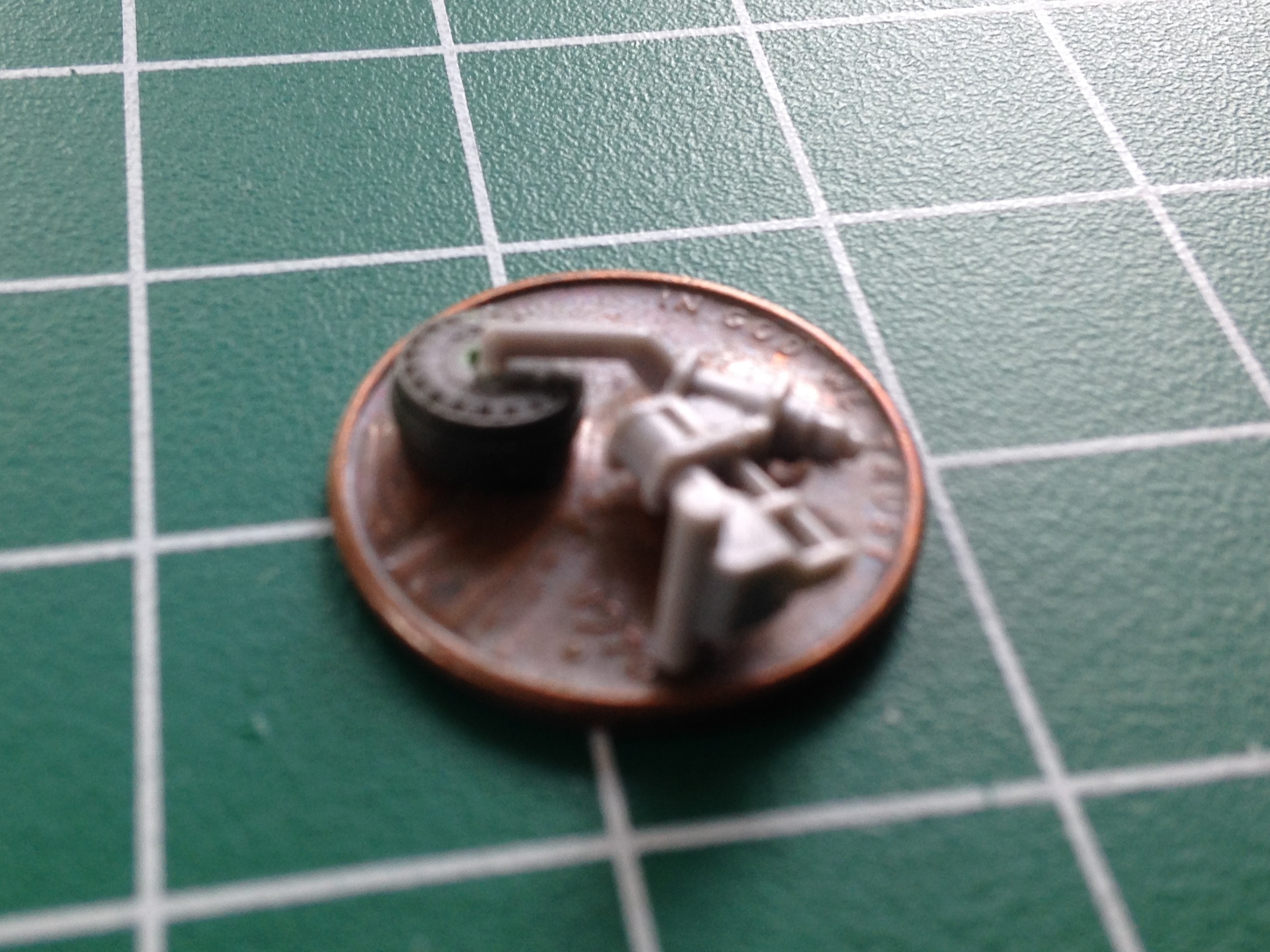
I have plans to build other Allison Mustangs, most of them are Accurate Miniature kits, and that means all the tail wheels are molded the way this one was. Being lazy, I didn’t feel like going through this process six or seven more times, so I made a mold of the tire and strut, poured resin, and will be using that instead.
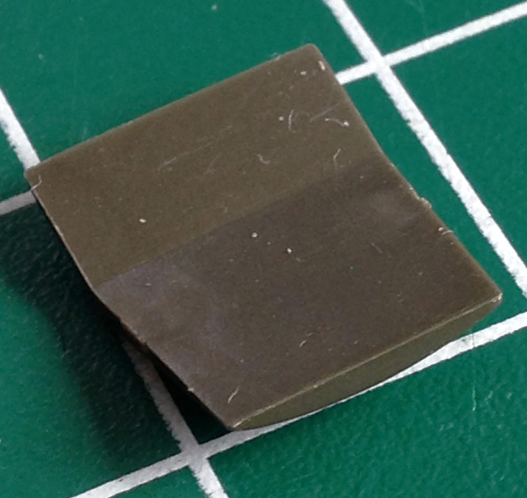
It seems that all solutions create new problems. I poured the resin for the tail wheel assembly, put it under 55 pounds (121.25kg) of pressure, and de-molded it the next day. See that white band on the strut? That’s a sodding bubble:

Okay, so that means I can either try another pour or fix this one. One thing I am more than lazy is cheap. Doing another pour means wasting resin (the smallest increment that can be mixed is an ounce…and I have NO need of that much resin just for this little sodding bubble). That means I cut the strut where the bubble is, add a disc of styrene (.015″ (.381mm) as it turned out), and finish it to invisibility:


At this point what’s driving the build is the need to shoot parts with aluminum paint. The end goal is to have everything painted so that I can join the fuselage halves. The rear landing gear strut needs to be painted aluminum, but so do a few more parts. So the next step is to get everything that’s going to be painted aluminum detailed and finished, and that starts with the main landing gear legs.
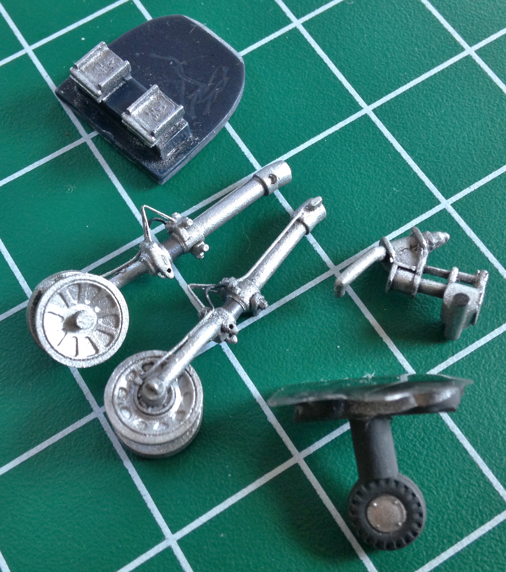
Aside from cleaning up seam lines, I also needed to drill out a couple of mounting protrusions and then turn them into two separate protrusions instead of one ridge as it had been molded. The needle tip points to the unmodified ridge and the finished strut is next to it:


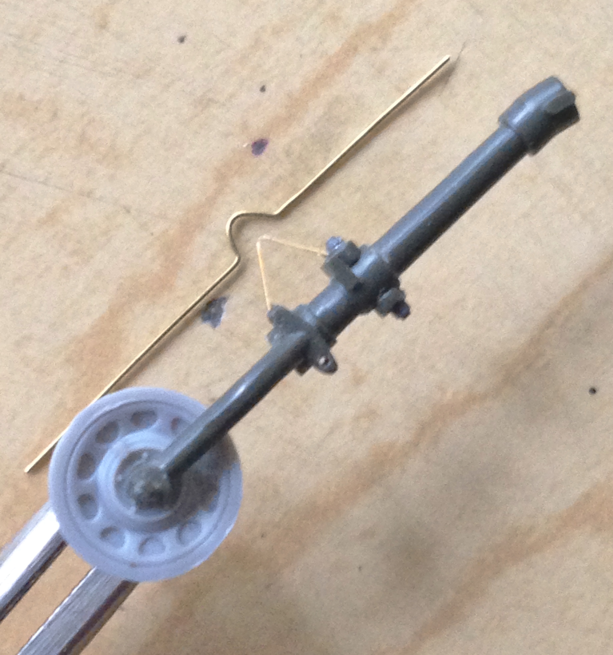
Then the extension scissors needed to be removed and replaced with more accurate photo-etched parts:
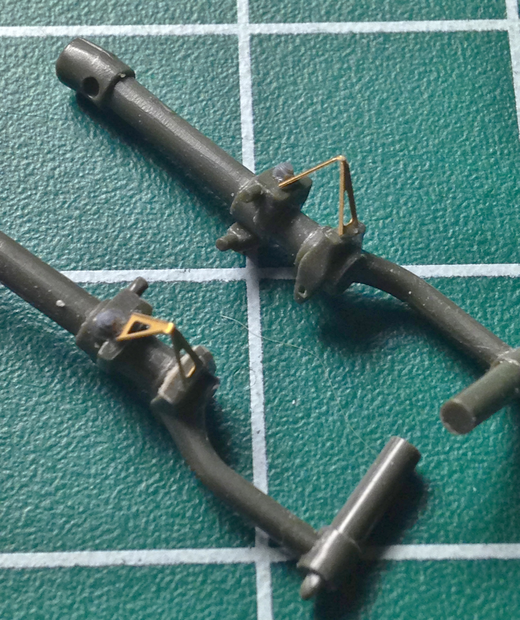
Next step was to add the brake lines. I used annealed copper wire (it bends easier) for the brake lines. Before the brake lines were added, I painted the steel section of the strut “steel” and then masked those areas off and then glued the wire in place before adding two bolts to each strut (if you look closely you’ll see the purple bolts):


With the struts detailed, it was finally time to toss paint at the parts, 75% flat aluminum and 25% semi-gloss black. I also loaded the airbrush with “rubber” paint and did the tires:

And while I had the “rubber” paint open, the curved section of the brake lines are rubber hose, so those got painted as well:

All the aluminum-painted parts were treated to a smoke-gray wash and the masking tape removed:
Then I needed to address the spokes. Once upon a time, I would have (and did) cut out the openings between the spokes. Then again, once upon a time my hands were much steadier than they’ve become. And even the painting showed me (again) that my hands are no longer quite (or even remotely) as steady as they were in my yout’.
I’m often asked by people how I can paint such TINY details. Being the smartass that I am, I tell them, “Carefully,” but there actually is a trick to it. Because the hands ain’t no longer steady, coloring between the lines ain’t no longer possible:

But there’s NO way I’m letting that kind of sloppy paint job stand. So when painting the tiny details, I’ll add the paint the details call for. Then I note the slop. Then I use the appropriately sized brush (usually TINY) to put back the paint my twitching digits slopped onto areas that the paint shouldn’t be on. Sometimes it takes several back-and-forth applications, but if I stick with it, I end up with something that isn’t sloppy. This is the same part as in the above photo:

One of the things that needed re-sculpting was the edge of the hood (aka, coaming) above the instrument panel. On the actual aircraft, there’s a hose that’s slit and slid over the edge of the aluminum. I’d briefly considered removing the molded-in ridge but the surface area the glue can work is VERY thin and stood a good (or bad, really) chance of dissolving it. Rather than go down that hole, I re-sculpted the areas of the lip that was out of scale. Below the section on the left has been done and the section on the right not done (sorry about the blurred photo…it was the best I could manage):

This variant of the Mustang had a separate door for the oil cooler and the kit provided the part. What the kit didn’t provide was a scale-thickness lip to it, so I thinned out that trailing edge of the oil cooler door:

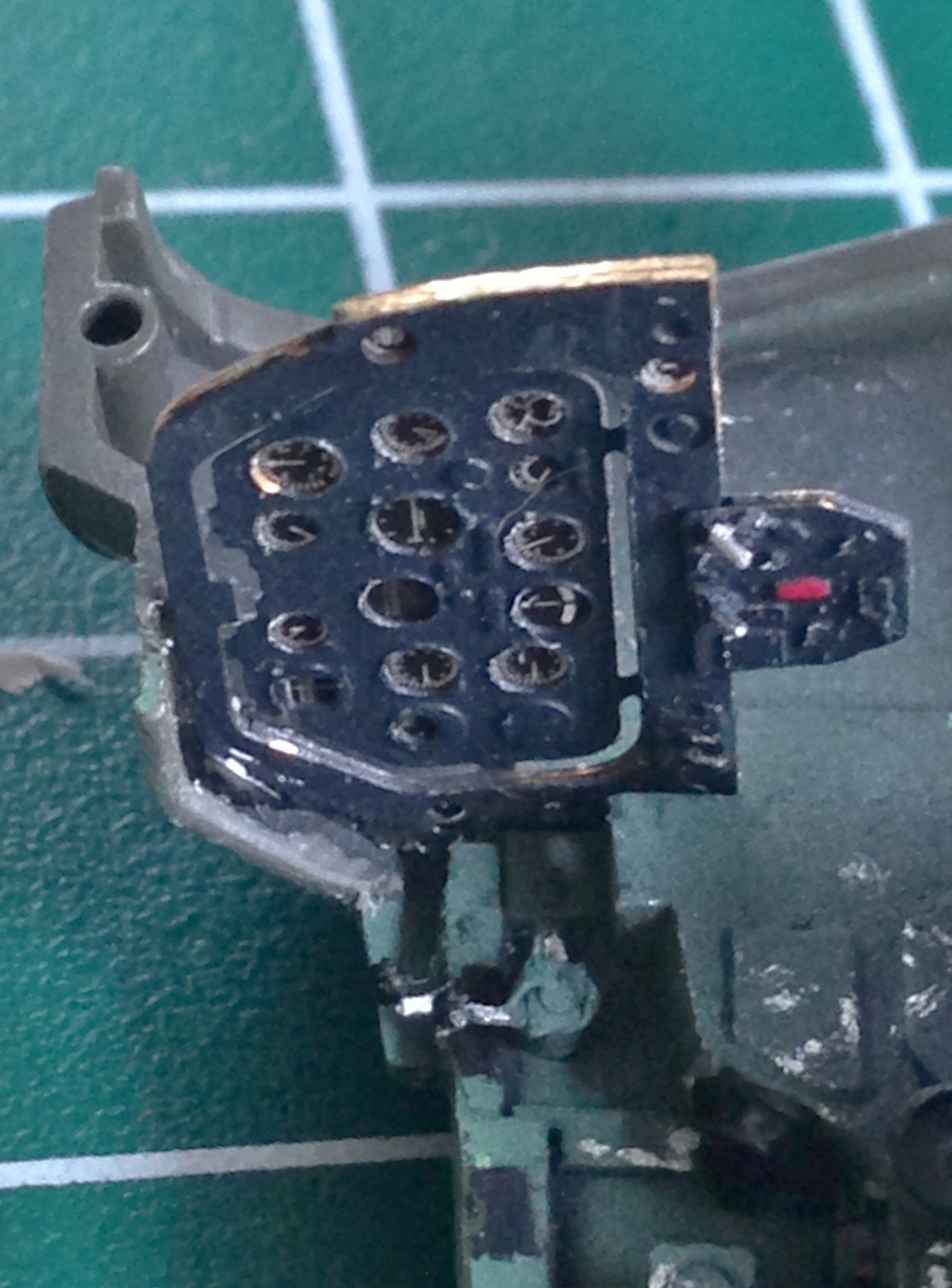
The last details to paint were the radios and those were done in semi-gloss black and chipped paint added, the seat and front bulkhead (with rudder pedals) were then glued into position:

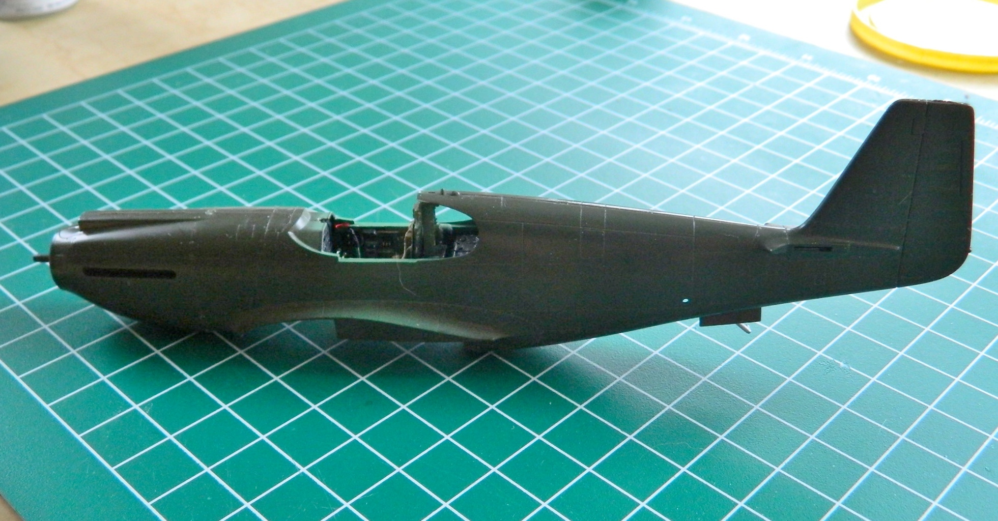
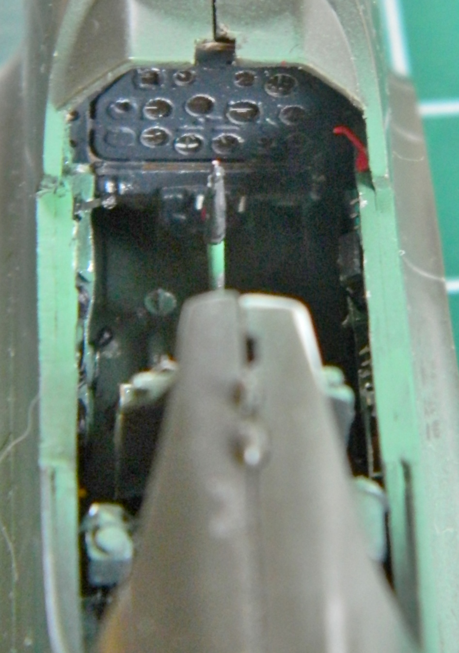
With everything painted, it was time to begin the installation process of the various sub-assemblies so that the fuselage halves could be joined. It started by assembling the cockpit and installing the instrument panel:
The first thing I did was to attach the engine cowlings to the fuselage sides. I’d debated joining the sides before attaching the cowlings but I decided that I would rather deal with one seam in an area that was easier to work than having that seam and the join where the cowlings met the fuselage. It took some time, fitting, additional invective, and more fitting before everything lined up as well as I could get it and then things were glued in and together:
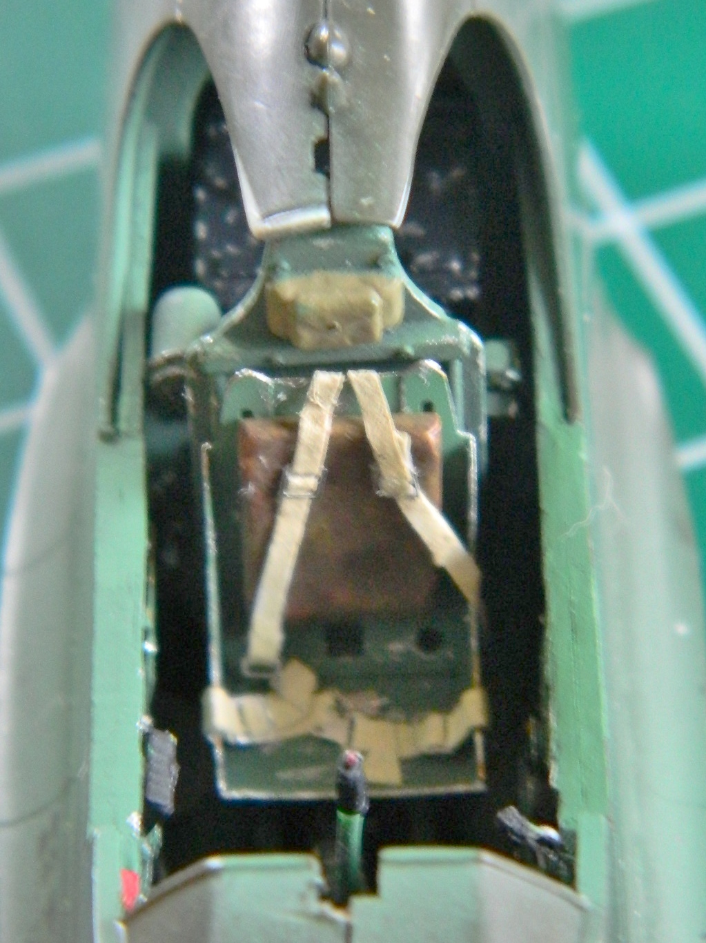
And in SPITE of all the careful fitting, heating resin and bending, there was still a fit problem; the front area of the cockpit floor was too low and you can see the gap between the floor and side (and the joystick was far too tall, so that got removed, trimmed, and re-glued). So there was more resin heating before I could glue and clamp things into the best fit I could attain:

With invective, heating, bending, and gluing accomplished, I am now here:

Now the seams all need to be dealt with. In some places I’m going to add sheet styrene and some places are going to need putty.
