With the (annoying) rear partition in place under both canopies, I started adding the structure, beginning with the rear canopy:

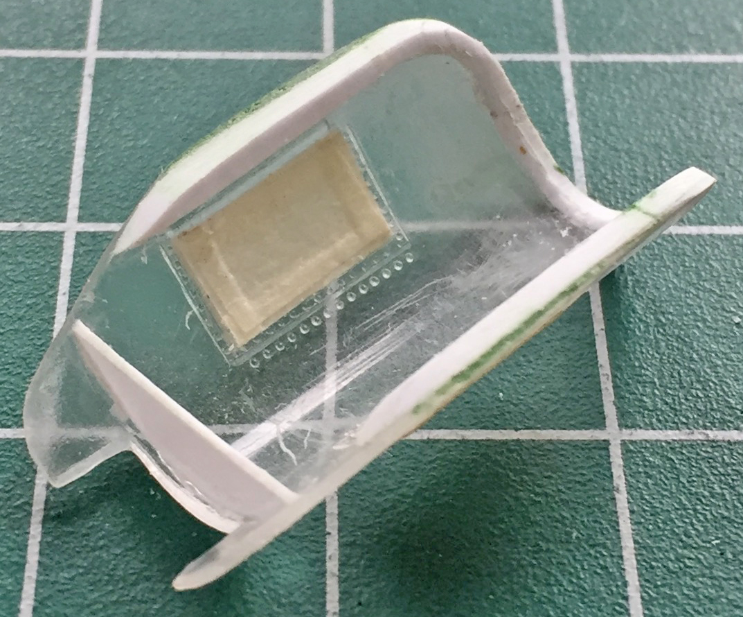
I kept adding plastic until the perimeter inside the canopy was covered, then there was A LOT of shaping to do. I’ve found it easier for me to scrape the plastic I don’t want there than sanding it away. I have much more control of where it comes off and how it comes off. With the basic structure of the canopy’s frame in place, I added putty to enable a smooth curve to replicate the actual framework:
As the putty was curing, I started adding structure inside the front canopy:

And entirely out of sequence, I taped together the major components (which also allowed me to see if the fit of the parts is really as abysmal as its reputation would have it…and oh my isn’t its rep well deserved). I’m building this one for someone who needs its measurements to see where he can put it when it’s (eventually) done. It’s one thing knowing its going to be a big one, it’s another thing seeing how freaking big it’s going to be:

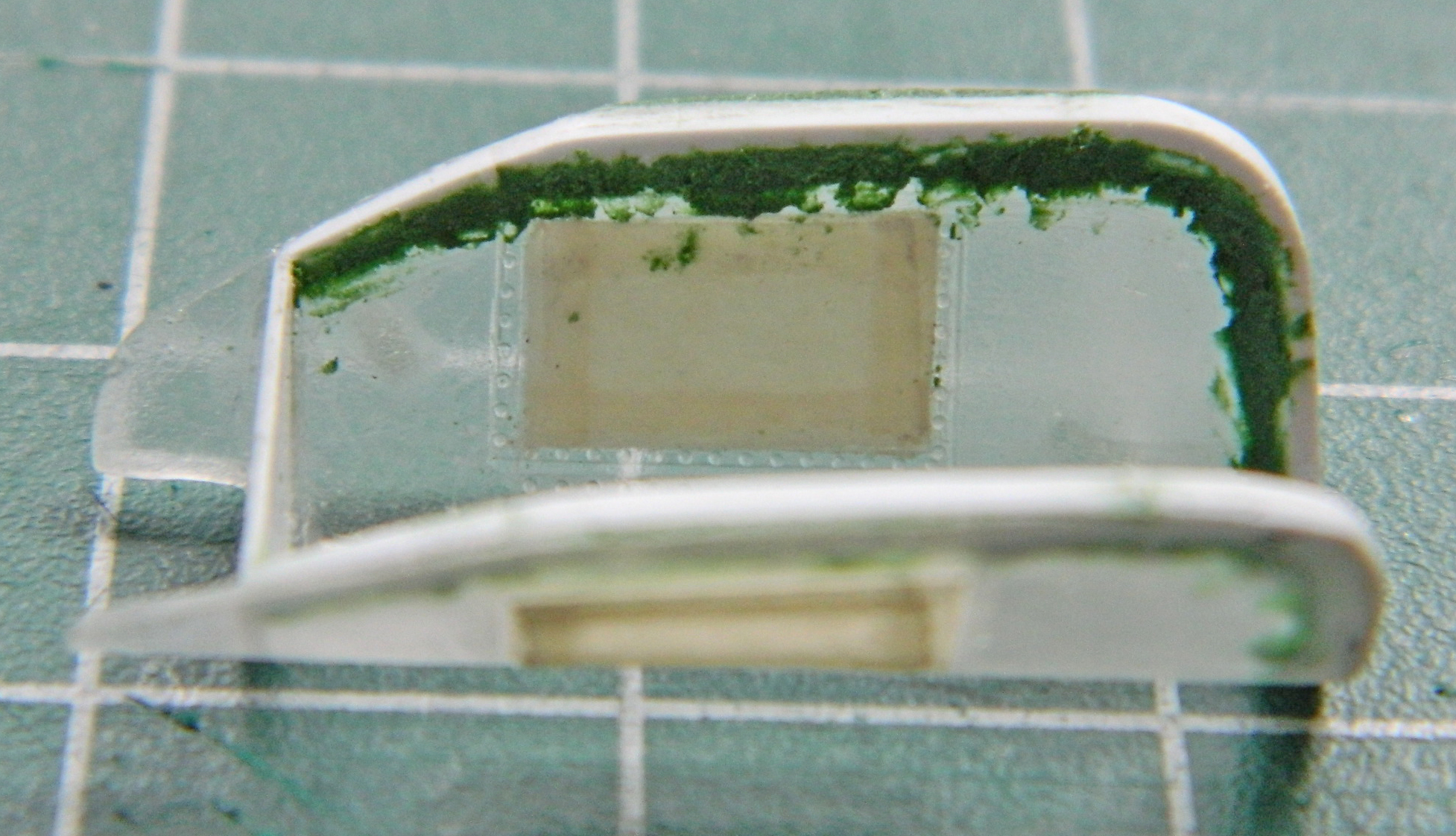
As with the rear canopy, once I’d added the plastic inside the canopy, many hours of scraping ensued. And then I noticed that the rear partition of the canopy was far too thin. ::sigh:: So that means I again get to fit plastic inside a curve (still my favorite) (spits). Once that was done I added more plastic inside the back “wings” on the canopies as the as-molded part was far too thin:
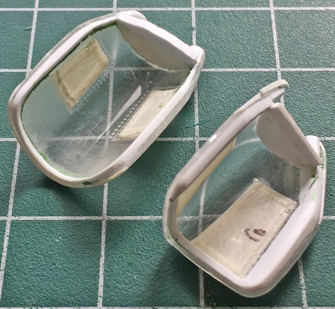
The rear canopy has roll-up glare shields (you and I would call them “shades”). I made a pair of those using .062″ (1.57mm) rod for the body and .005″ (.127mm) sheet for the end plates. These will be installed much later on; if they’re glued in now I won’t be able to get at the tape to remove it. I also added a few more details (with a few more to come) and did both canopies that way (the glare shields in the front canopy are entirely different and will also be done later):

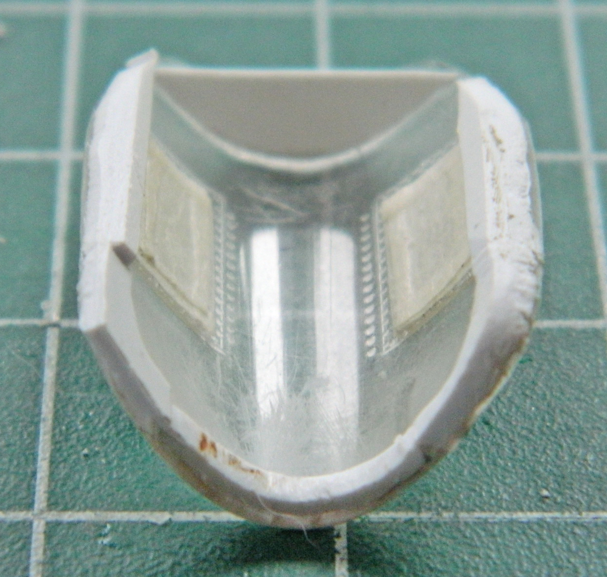
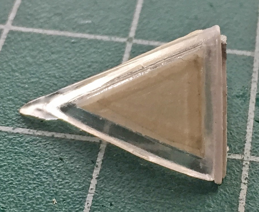
Last was the front windscreen. The sharp tip is a bit too sharp and not correctly shaped. The point of the windscreen stops at the raised line (more about those shortly):

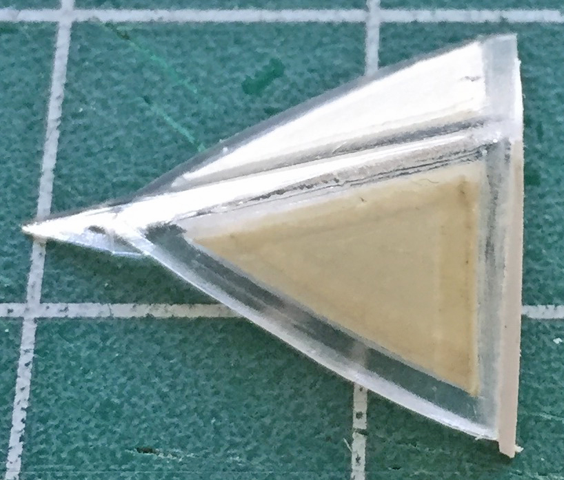
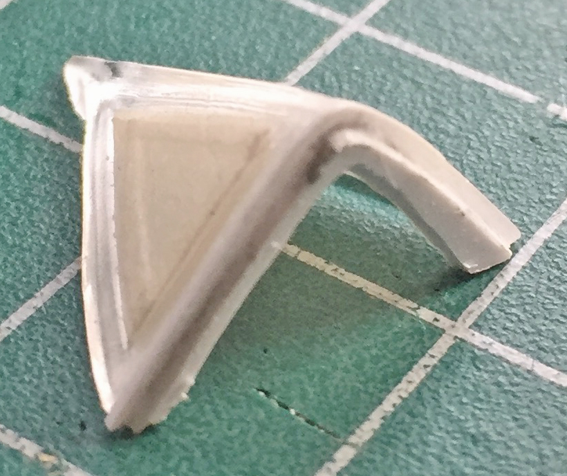
I cut the tip off and reshaped it to fit accurately, then I started on the inner framework of this part:
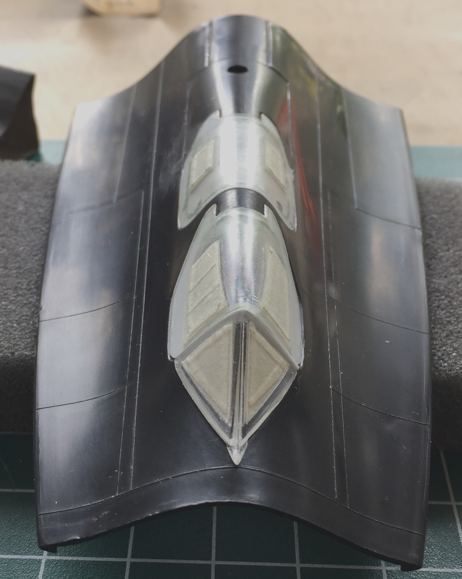
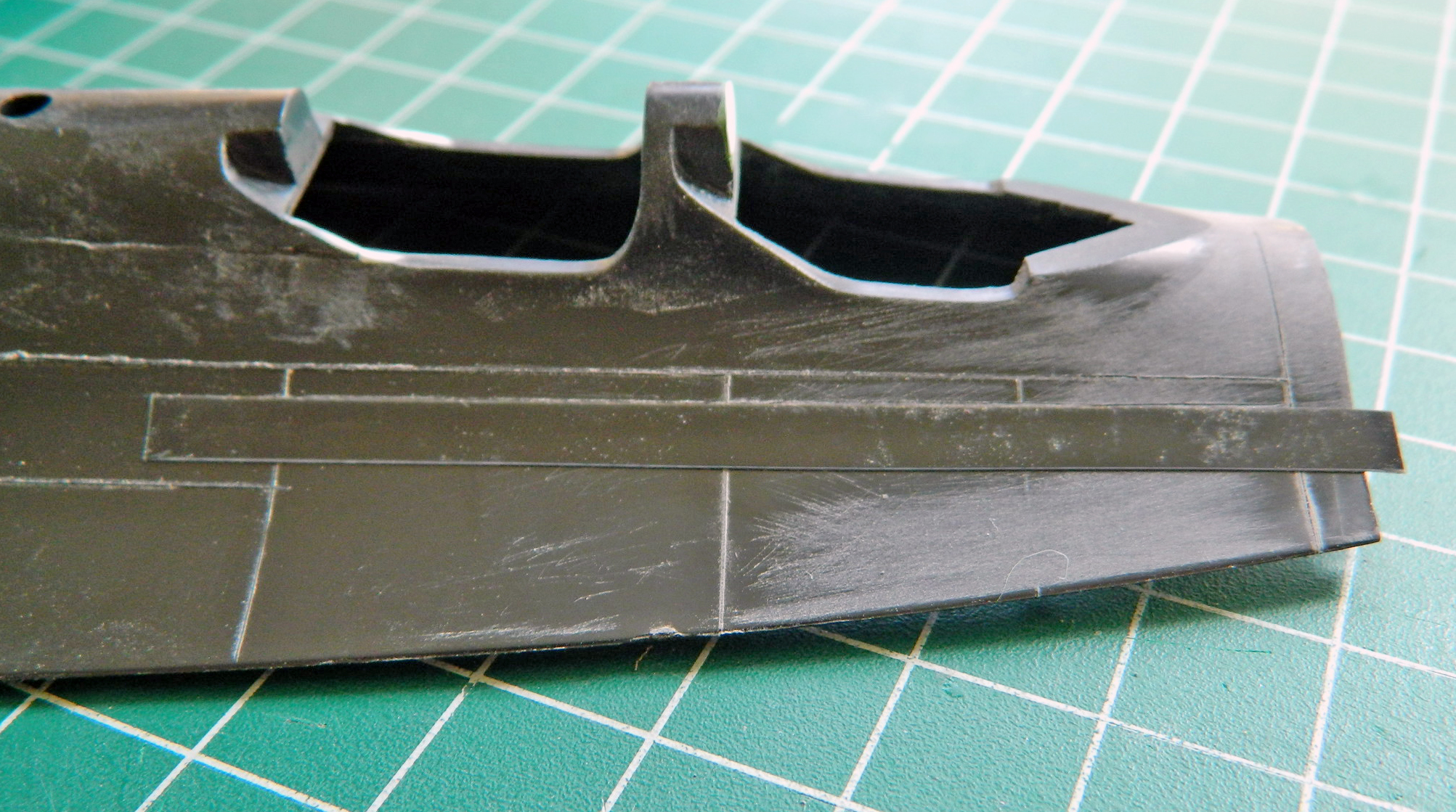
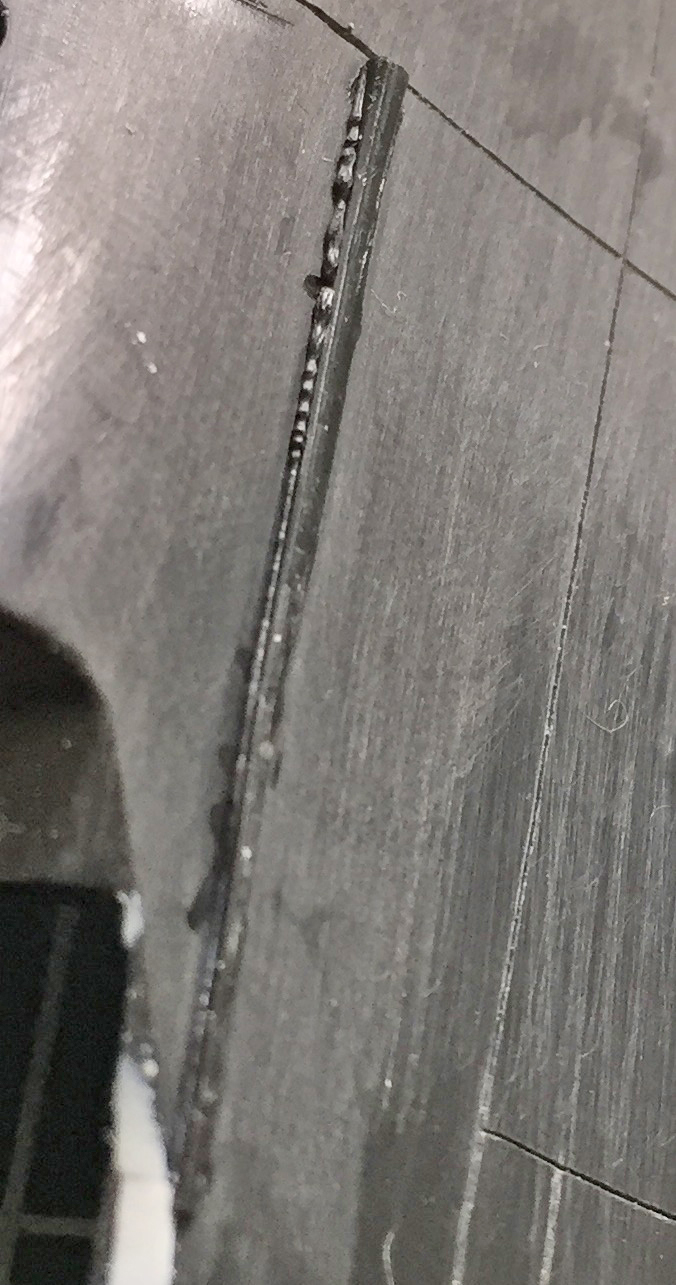
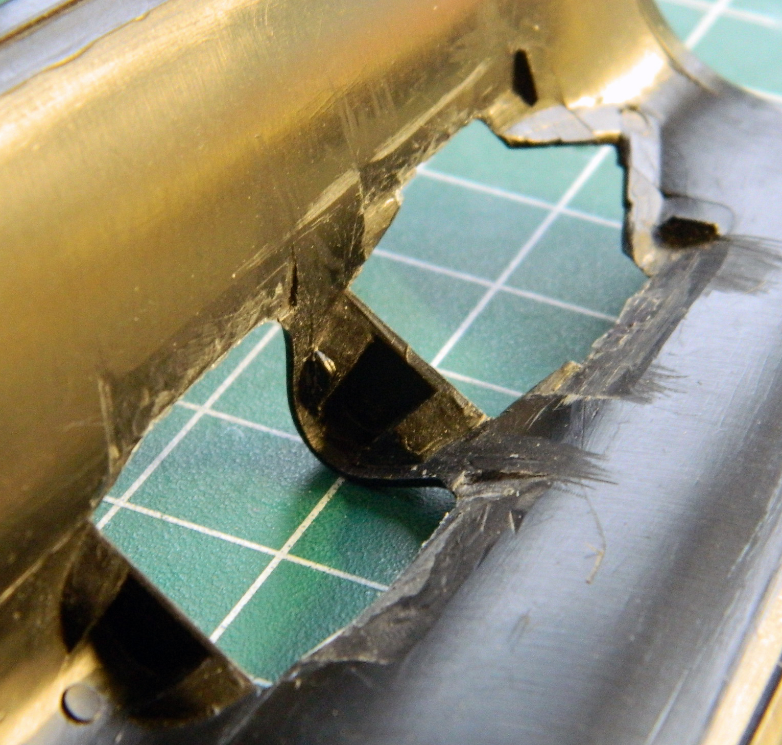
Yeah, so, the raised panel lines. Back in the mid-60s through the 70s, when the dies were cut it was a lot easier to create raised lines. One simply cuts them into the face of the molds. Recessed panel lines mean that the entire surface of the die that creates the surface shape(s) have to be recessed so that the panel lines can be raised in the mold and thereby create recessed panel lines on the finished part(s). That has to be much easier with CAD/CAM than cutting the dies manually. So all the lines shown below are raised and have to be scribed into the surface:
Well, I absosoddinglutely SUCK at inscribing panel lines. TOTALLY SUCK AT IT. I have two different types of scribers, mistakenly figuring that maybe one of the types I can get to freaking work (and now I have even more scribers…so many of them that if I had a wazoo, that’s what I’d be keeping them up into). Uhm…no. I can’t. One little bobble and the line is wrong. I really do not want to ruin whatever other work I’m doing on this build with lousy, irregular, not-quite-straight panel lines. After I screwed up two lines back to back, I stepped away (GLADLY) to reconsider Things…and to let my blood pressure drop back to normal.
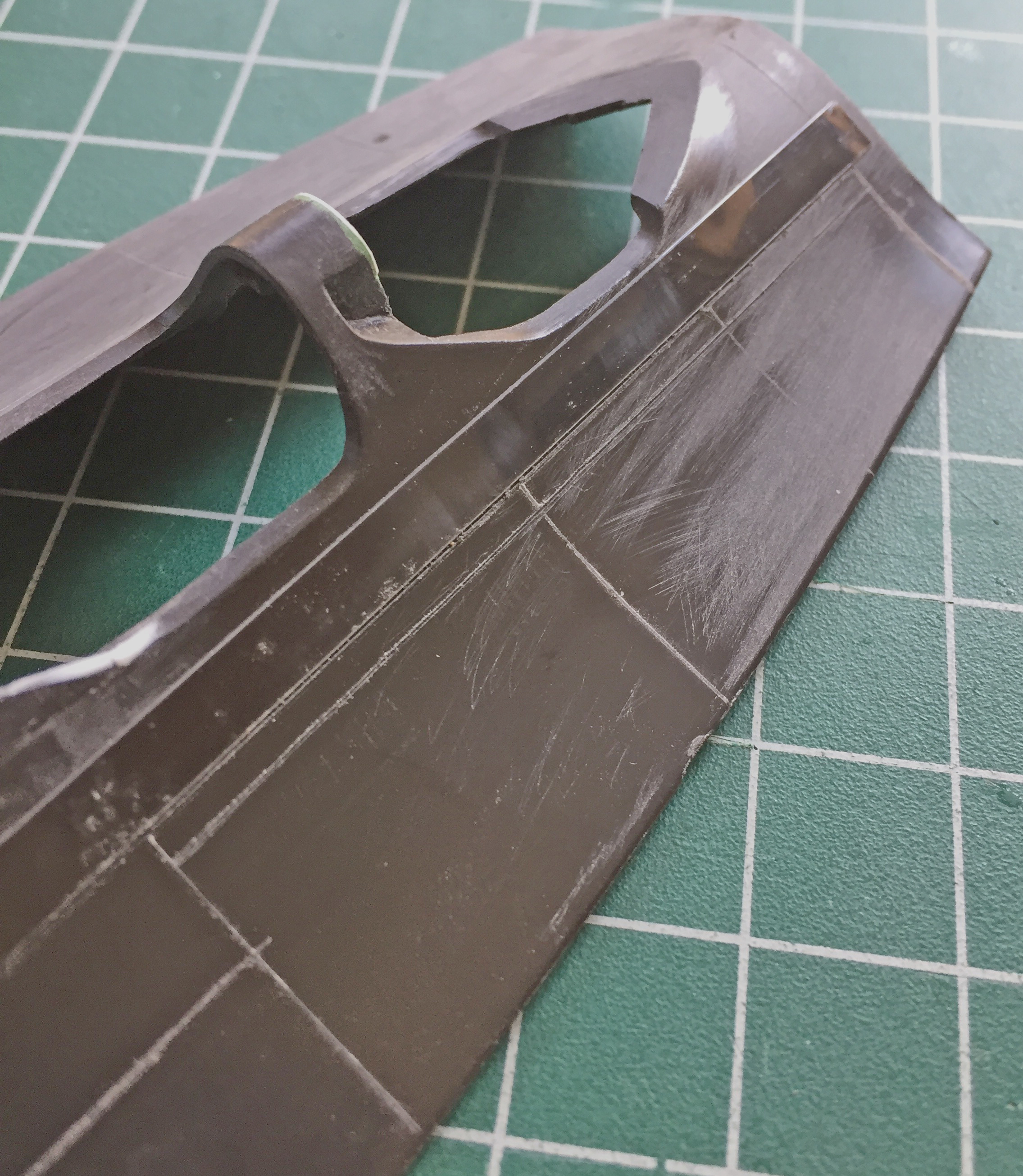
Then something novel happened. I had a thought! Once the, well, novelty of that subsided, I decided to try it. (What’s the worst that could happen? I’d screw up a line or two? Already managed that.) What I tried was going back to an old-school technique. Instead of using dedicated panel scribers, I used a needle. AND I used Dymo label tape as my straight edge:
And gawDAM didn’t that work out just fine! The process is to lay the tape right next to the raised line then, holding the needle mostly vertical to the surface, lightly drag it along where the panel line goes. Several drags of the needle lightly result in a much better outcome than trying to do it in a pass or two…and if (when) the (old) hand bobbles, a light line is easier to sand out:


Then I had to fix the two uneven lines I’d scribed in. In dealing with plastic and putty, their physical properties are much different. For all its flexibility, plastic is a solid and putty is not. Even though the particles are small, putty is granular. Dragging a scriber or needle across putty results in it chipping and coming out unevenly. My way around it is to use stretched sprue to fill the lines that don’t pass muster. The sprue is laid along the section to be filled and styrene cement applied. I wait a minute or two and then press the raised sprue down firmly. The dissolved plastic then squidges out and downward, completely filling the space I want to be filled. The real trick to that is to wait until the cemented plastic is totally hardened. Not doing that results in blobs of it either pulling away or not scribing sharply. Each time I fill something this way, at least two hours needs to pass, more if the plastic applied is thicker. (I’ve since modified that procedure. I now let the work sit overnight before I go back at it so that the glue has cured totally.)
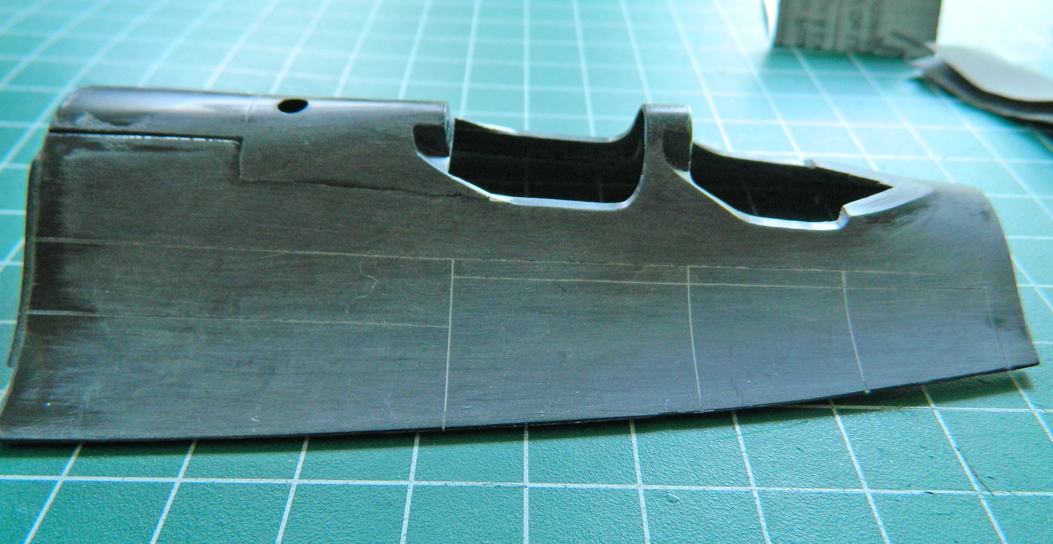
Once the cement had set, I re-scribed the filled areas and then sanded the surface progressively through 320, 400, 600, 1200, and 2000 grit paper. Use wet/dry paper wet. It keeps the dust down. The needle worked great. The lines are uniform in width and depth:

This is one of the better fitting panels I’ve encountered so far. No, I’m not being sarcastic (for a change…don’t get used to it). Because of the depth and width of the poor fit and the fact that these areas would get scribed, I decided I’d also fill these sections with stretched sprue:


It turned out that because of the thickness of the applied sprue I had to wait overnight to remove the excess (and then go back and add more sprue in the section I dug out improperly because I only waited a couple of hours) and scribe the panel lines.
I added the cockpit sills from the AM resin detail set:
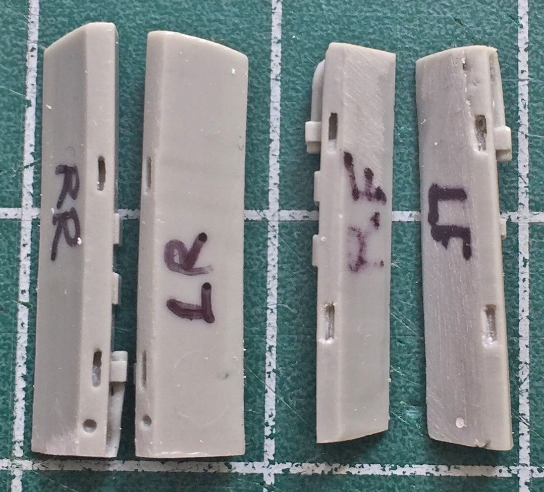

It’s common for resin parts to require fitting. If I just glued them in the result would have been cockpit sills that were far too thick:
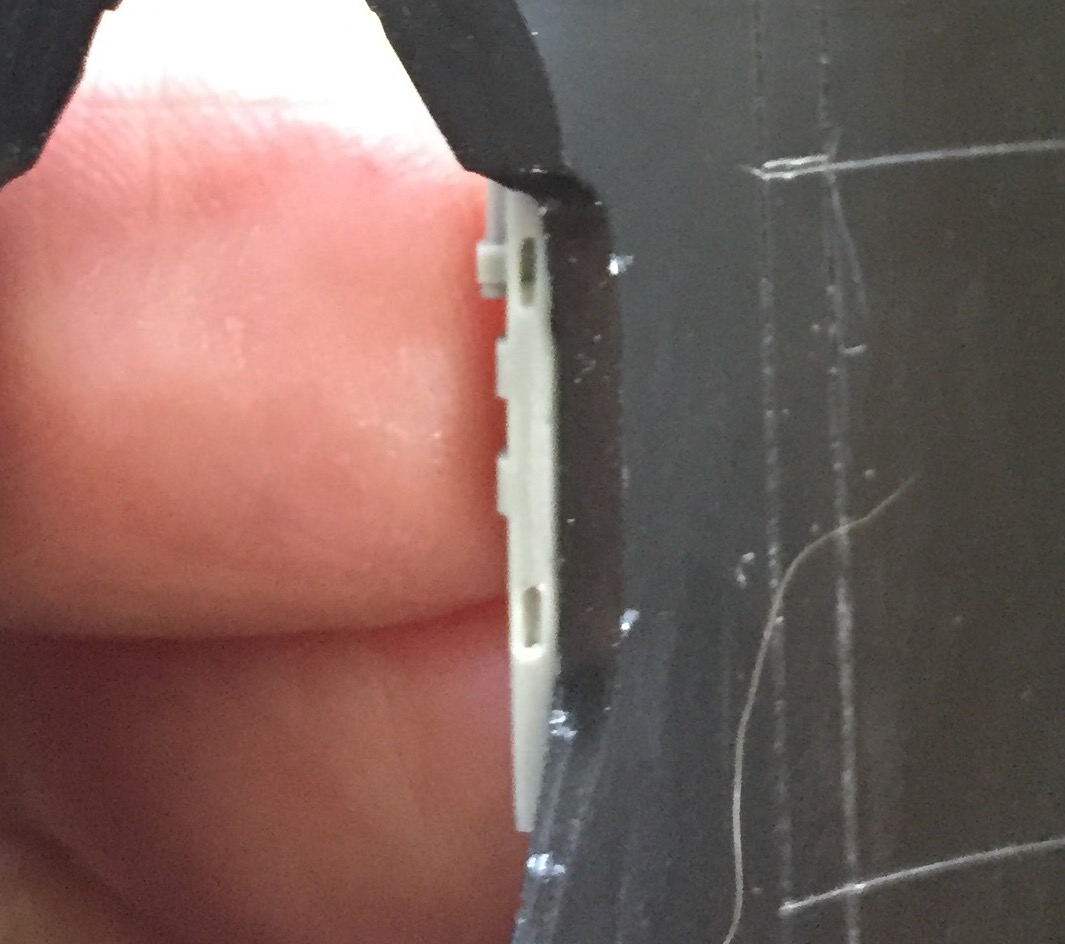
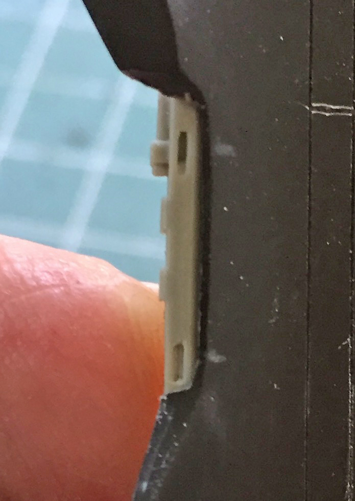
First I thinned the sills by scraping:

Then I had to “socket” the resin parts because though that above photo looks like it’s thin, it’s only the edge that is. Behind that edge the plastic is thick:
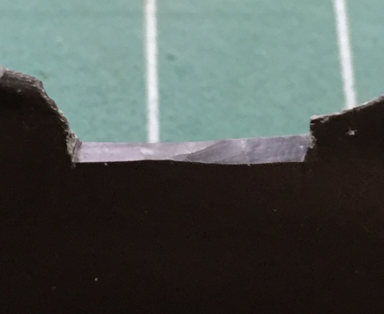
There was a lot of cutting scraping required to get the resin sills to (relatively) fit:
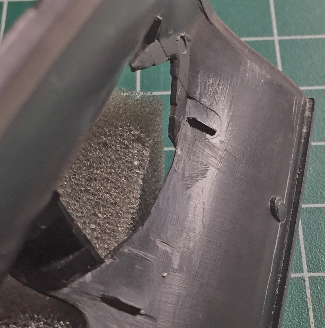
There was even more scraping and cutting to get the sills to nestle into position but the end result seemed to work (more on that later, too):
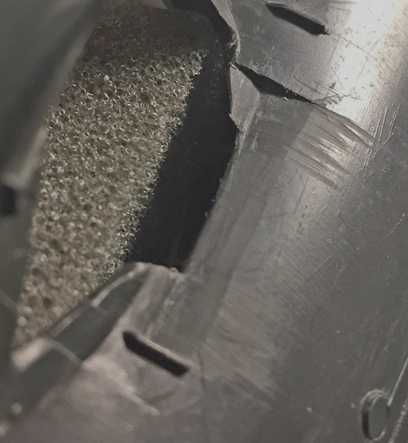
Having gotten all four sills to (relatively) fit, they were glued into position. There was a small gap at the edges of all the sills where they (relatively) met the side of the cockpits. That gap would need to be filled.
Some resin will bond with putty and some won’t. This formulation of resin just shrugged off the putty so that meant I’d have to find some other way of filling that gap. I tried gap-filling superglue. That stuff stays gooey for a long time so after it was applied I let it sit overnight…and then I tried to file it down. Tried to. I suppose I could have gotten it to work but it was a STONE BITCH to do and I simply did not like how it turned out. In order to get that gap completely gone, I would probably have to spend a week just on the sills. Oh. And another problem. The edges of the cockpit where they curve upwards was not working well with the superglue. There’s no seam there and no matter what I tried (short of spending a week on it) the seam was still visible.
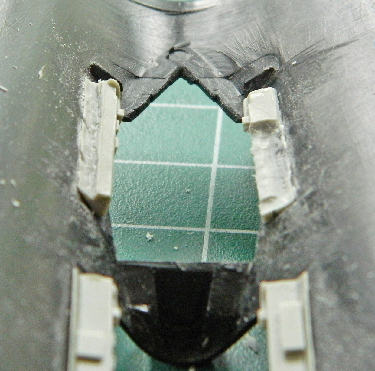
And then I tried fitting the cockpit parts. In short, I had to remove substantial areas of resin so that the cockpits would fit, albeit poorly:
I decided there had to be a better way and as soon as I postulated that, I figured out a better way. Remove the resin sills entirely and scratch-build the things! That would solve all the blending problems. Using styrene would allow the putty to be effectively used and make blending the sills with the curved sections MUCH easier.
So I popped them out:
Since I was getting the cockpits ready for paint, I added the very small buttons and trigger to the joystick using stretched sprue and a small piece of .005″ (.127mm) for the trigger (can’t see it in these photos):
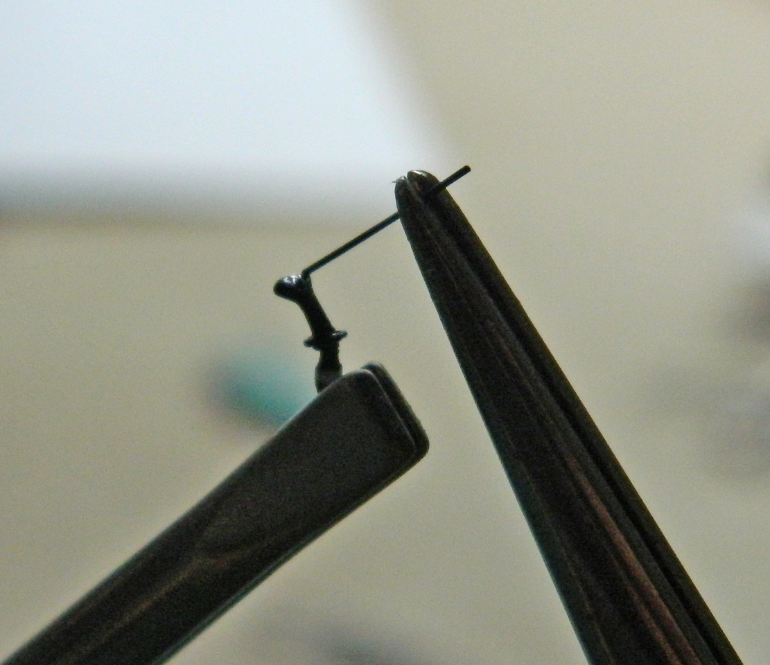

And right after these photos were taken of the joystick, during the final trimming of the buttons I managed to snap the grip off the stick. I reattached it and the glue is curing now.
::sigh::
