My initial intention was to scratch-build the instrument panel. I don’t think either the kit-supplied part or the resin AM replacement offered anywhere near enough (accurate) details. There’s a company in Poland, Elementy Do Waloryzacii Modeli Plastikowiych, that makes a very nice photo-etched detail set for the P-51A (#S48-111). Since the differences between the P-51 and the P-51A cockpits are minor (no bomb/drop tank release, as the P-51 had provisions for neither), I picked up a set. I like PE parts for some things and I don’t like them for other things. The determining factor is the thickness of the metal being used. Sometimes it’s spot-on, other times it’s too thin. But since it was my intention to scratch-build the instrument panel anyway (using the Waldron instrument faces), I didn’t really think that would be a consideration. I used the PE part as the template and used my (freshly sharpened) panel scriber to cut closely around the PE template to create the panel’s frame and inner panel (they’re separate on Mustangs). To keep things from moving around, I taped the PE sheet to the plastic sheet and had at it:


Waldron’s punch and die set was a bit more than my wallet would bear, but Micro-Mark offered a cheaper set which I bought. I checked as closely as these 66-year-old eyes would allow seeing if the punch sizes worked with the gauge diameters (and they do) and then started punching holes in the plastic panel:

“I didn’t really think” is the operative phrase, there. The short-form of the problem is scale thicknesses. I came up just short of the room required to make an accurate representation of the locations of the gauges. I needed a few scale inches more width than reality provided to get everything to fit that I didn’t have. I briefly considered thinning the plastic on the fuselage sides to get those inches back and then realized that that would be SUBSTANTIALLY more hassle than simply using the PE set’s instrument panels (and beautifully reproduced gauge faces) and create other problems that I needed like I need a third buttock.
In looking at the brass and gauges, I realized I have no idea how to paint it and put it all together, the problem is in masking the three freakin’ tiny gauges that are located in the panel’s outer frame. Well, while (what’s left of) my brain worked on that conundrum, I started work on getting the rest of the cockpit to play well with each other and fit inside the fuselage.
As stated in other places, I use copper wire, solder, and lead wool to replicate lines and conduits. Copper wire, solder, and certainly lead wool are not provided in straight sections, which are much more handy to work with and are often required to be straight. So how do I get from this:

To this:
By using these. The clear pieces are old acrylic covers to welding masks (the type that doesn’t auto-darken). I tease the wire, solder, lead wool, into roughly a straight section, then I lay the piece I need straightened on one surface (usually the acrylic plates for solder and lead wool and the metal plates for copper, though I will use the metal plates for thick solder and the acrylic plates for thin copper) and gently rub the two plates against each other:

Once I had the copper wire straight, I folded it in half and twisted it:


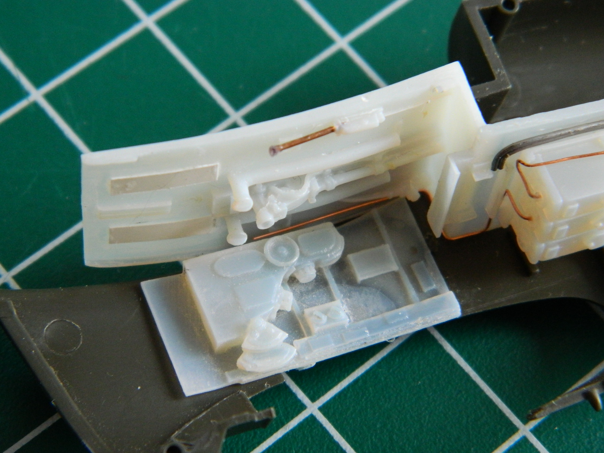
The lower radio shelf was glued to the floor section and conduits of copper wire and solder were added as well as adding the rollover brace to the armor plate, adding the junction box (the white part) to the brace, and then wiring them up:
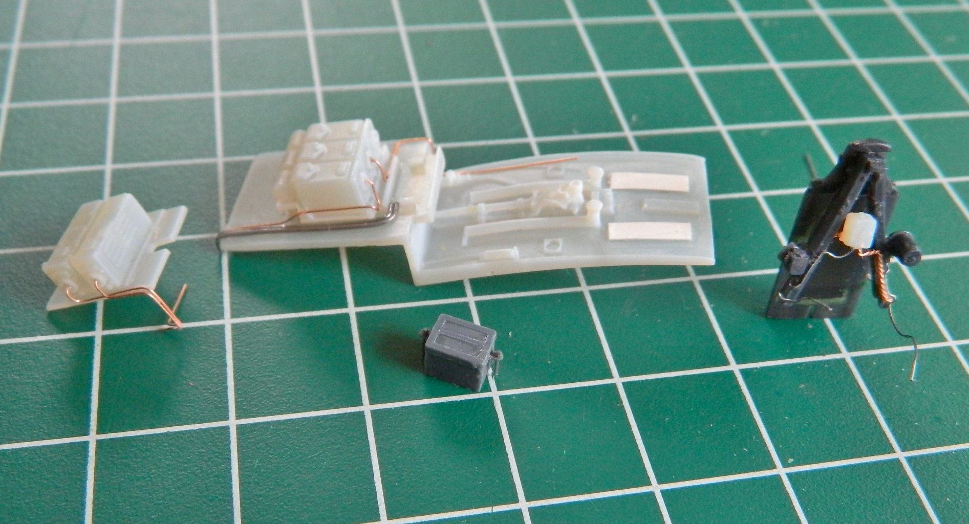

The cylinder on the floor to the right of where the pilot’s seat goes is the emergency hydraulic pump and as such it gets a handle. I drilled it out to accept a copper wire (cleverly straightened out as mentioned above) and then needed to make a knob for the end of it. Often white glue is used to make knobs of this sort, but the actual knob has a flat end which I could not replicate with the white glue. So I dipped the end of the wire in a small puddle of superglue. One of the interesting things about superglue is that when not used to bond things together (hides scarred fingertips behind back), it takes a while to harden and goes through a semi-hard stage. When the blob of superglue became milky, it wasn’t hard yet but had gone past the liquid state. At that point, I pressed the end of the blob against a flat surface and the result was a knob with a flat end just as I wanted:

Sometimes not having four hands (or more) to dry-fit parts is a genuine annoyance. The work-around is to tack things in place with an adhesive that allows easy removal of parts only temporarily in place. If I’m dry-fitting resin, Contact Cement is good for that. But the solvent in Contact Cement will attack and dissolve styrene (don’t ask how I found that out) so when tacking styrene parts together, I use white glue, which is how I attached the two side panels of the cockpit to the fuselage halves:
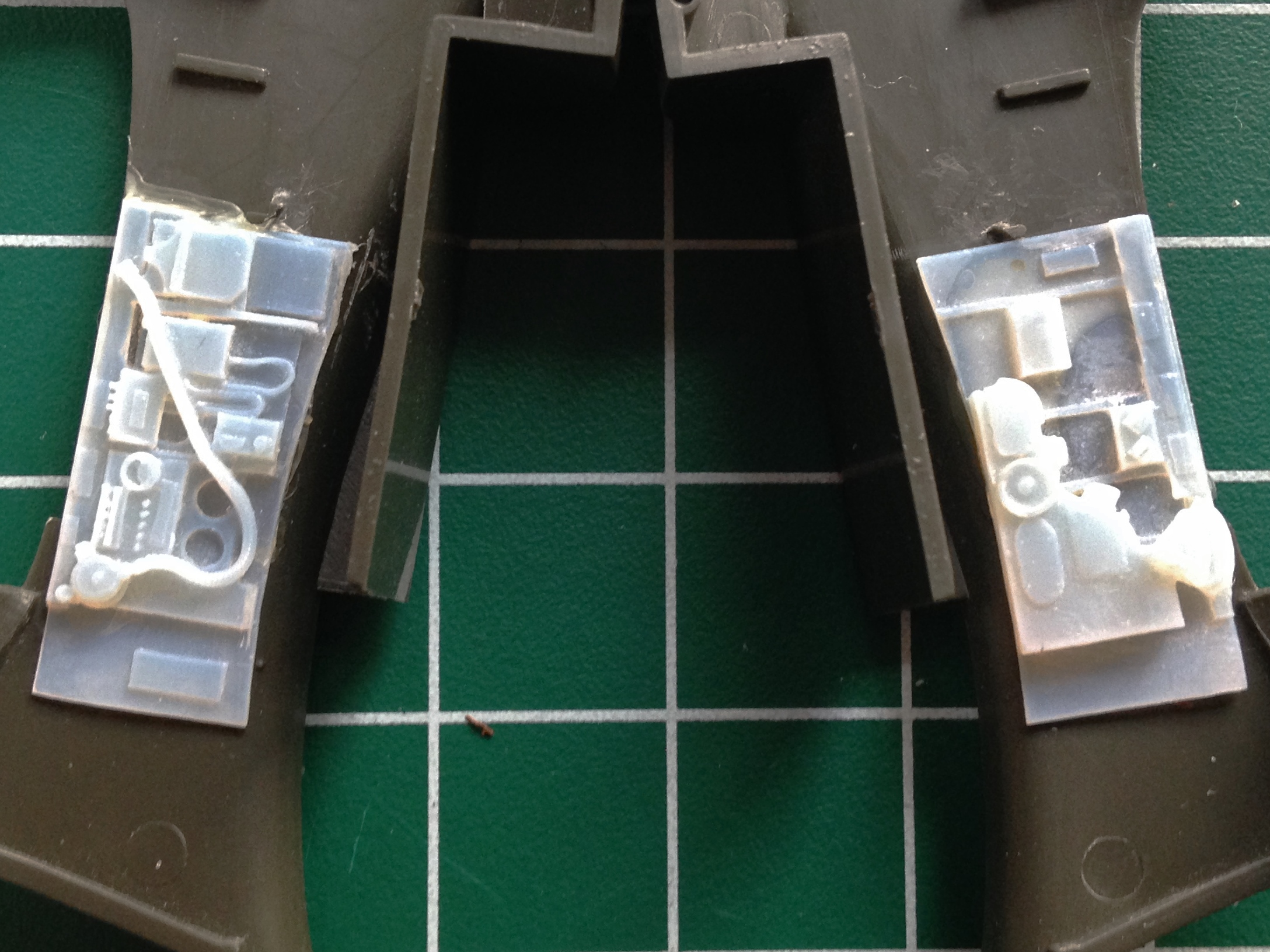
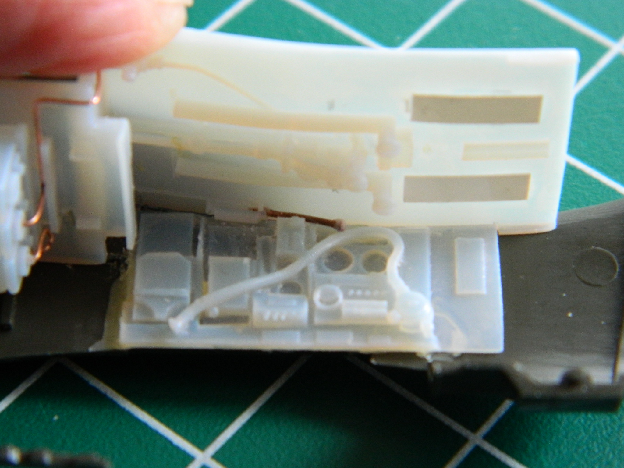
It didn’t take long for fit problems to show up. You’ll note that the bottom of the side console is straight and flat. But the floor section it’s to meet with isn’t flat and straight. And in the lower right photo, you’ll see that there is a substantial gap at the front (to the left in the photo) where things are supposed to meet:

And not only that but the bottom of the side console also doesn’t match the face of the floor across its surface, as evidenced here (I drew a pencil line, only barely visible in the photo, at the bottom to show what needs to be removed):

And yes, I have the same problem on the other side, too. And in addition to that, there’s NO WAY the carefully constructed pump handle will fit, either:

So much hilarity, gaiety (and invective) ensued as I trimmed, sanded, filed, heated, and bent various resin bits to play well with each other:

And I also had to get creative to get the pump handle to fit around the box on the cockpit side. No, the original handle isn’t bent. Then again, the original handle doesn’t have to fit inside something a half inch wide by three-quarters of an inch long, either:

Another fit problem was created by the molded-on oxygen hose, so that had to be carefully removed:

I found a great replacement, it’s actually a rubber-like material, and will conform to the space it has to occupy:

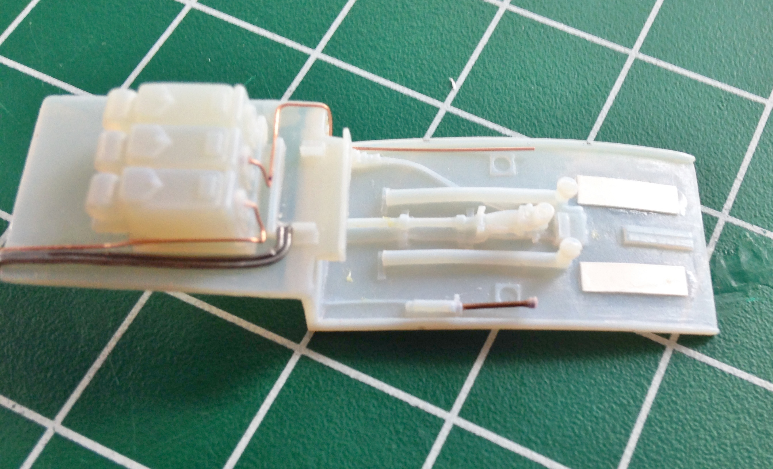
Looking at reference photos (something I did merely for the novelty of it), I see that the wiring looms/harnesses are quite evident as well as being absent from the resin part. I have a spool of 40 gauge magnet wire that I’m using to create the wiring. And 40 gauge is REALLY small stuff:

By folding the wire, I created two lengths of eight wires each and twisted them into one cable:

An eight-wire cable is attached to the electrical breaker panel:

The other eight-wire cable was split into two four-wire cables and attached to the radio control panel (on the left) and the microphone panel (on the right). The oxygen hose will be attached later:


