Then I noticed a production flaw with a resin part. This goes at the rear of the tank. Inside are the radiators and the outside is air-flow ducting (which is the part that’s up and showing). Not only is the ducting not quite correct even without the production flaw, if you look at the end of this piece closest to you, you’ll see a curved piece of resin above the straight section that’s below it. This is a gap created by the mold halves not being correctly assembled before the resin was poured in. This resulted in a gap, which in scale dimensions means that this section of the part is three scale inches (76.2mm) too thick:
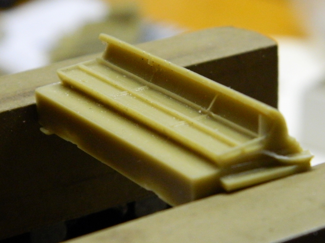
Ain’t that splendid. Yet even with this flaw, it was still easier/quicker to rework the resin part than to scratch build a replacement for it. So that reworking starts with a large bastard file taking down the surface of the part and getting it correctly dimensioned:

So I was stumped at this point. Well, since I didn’t know how to proceed, really, I figured I’d work on something that I did know how to proceed with while the back of my brain worked on the problem and came up with a solution.
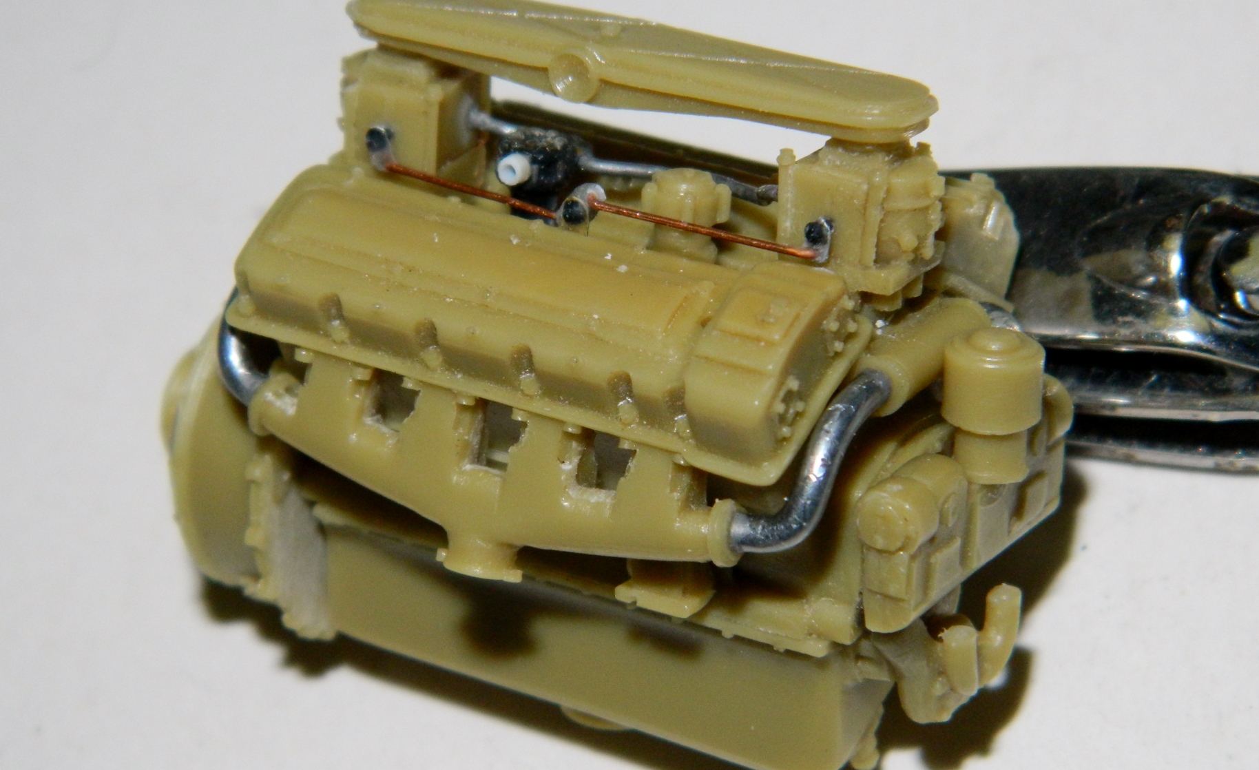
I drilled the center of the fuel pump mount and added a small copper wire to use as a locating pin and drilled a hole in the top of the engine to accept it. Dry-fitting showed I got it positioned correctly (or so I thought…later on I ran across a photo that showed I got the mounting of the fuel pump wrong but nobody will know it but me and I don’t destroy anything by trying to separate that which is held in with cured superglue):

Before I glued the pump to its (incorrect) location, I added a piece of plastic rod for where the fuel line from the fuel tanks attaches and then drilled it out to accept another solder line:
I also had to add the pipes that connect the exhaust manifolds to the carburetor heaters. I tried plastic rod but the bends required kept snapping the rod. I tried copper wire and at that length it is FAR too stiff for my ruined wrists to bend the way I needed to. Then I realized that solder might work so I ran out and got another roll of solder of the necessary diameter and that worked just fine. The solder is the silvered colored tubing:


With the fuel pump now glued on, I added the fuel line to the carbs (the plenum is just tacked in place with double-sided tape for fit):

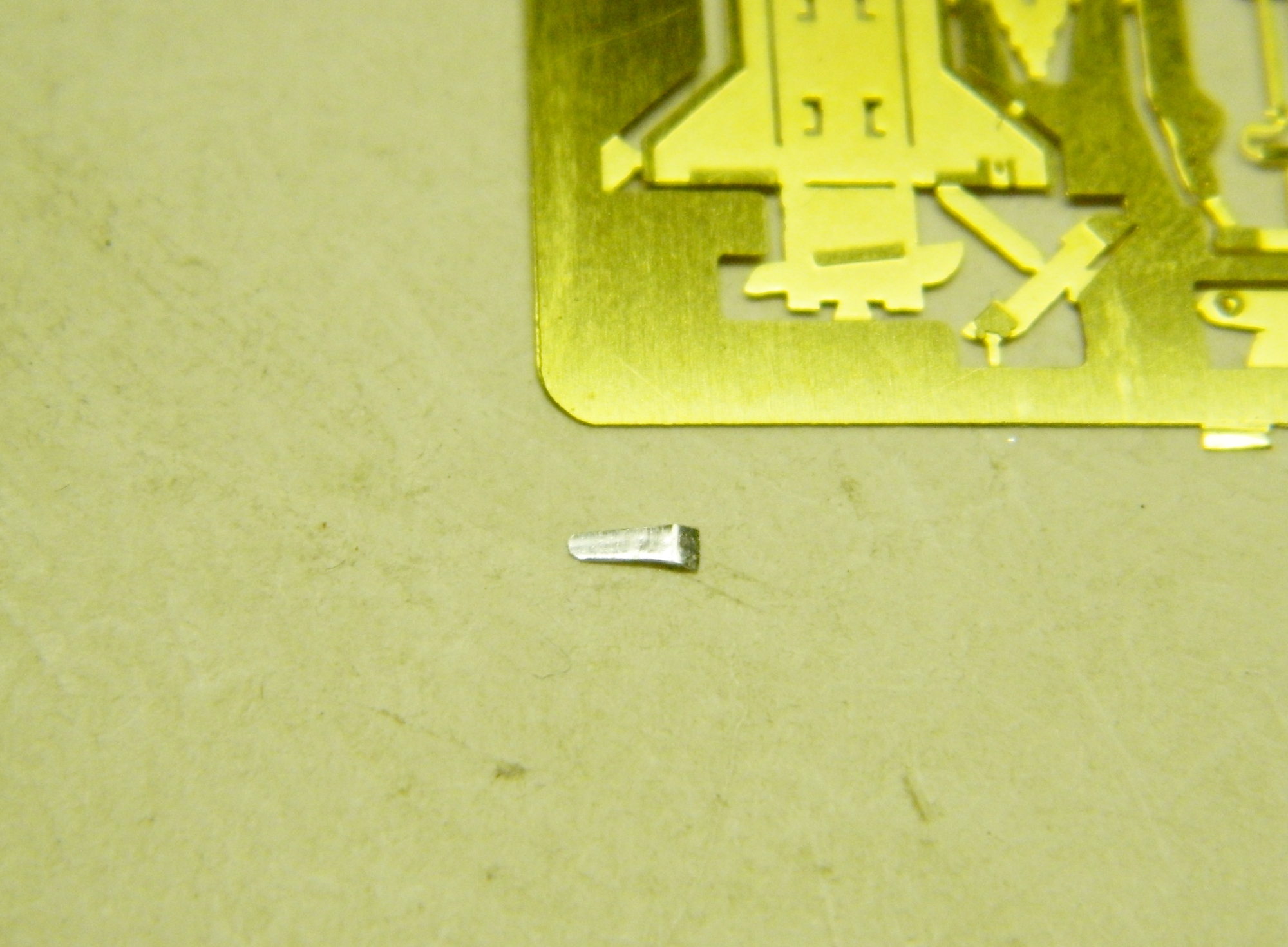
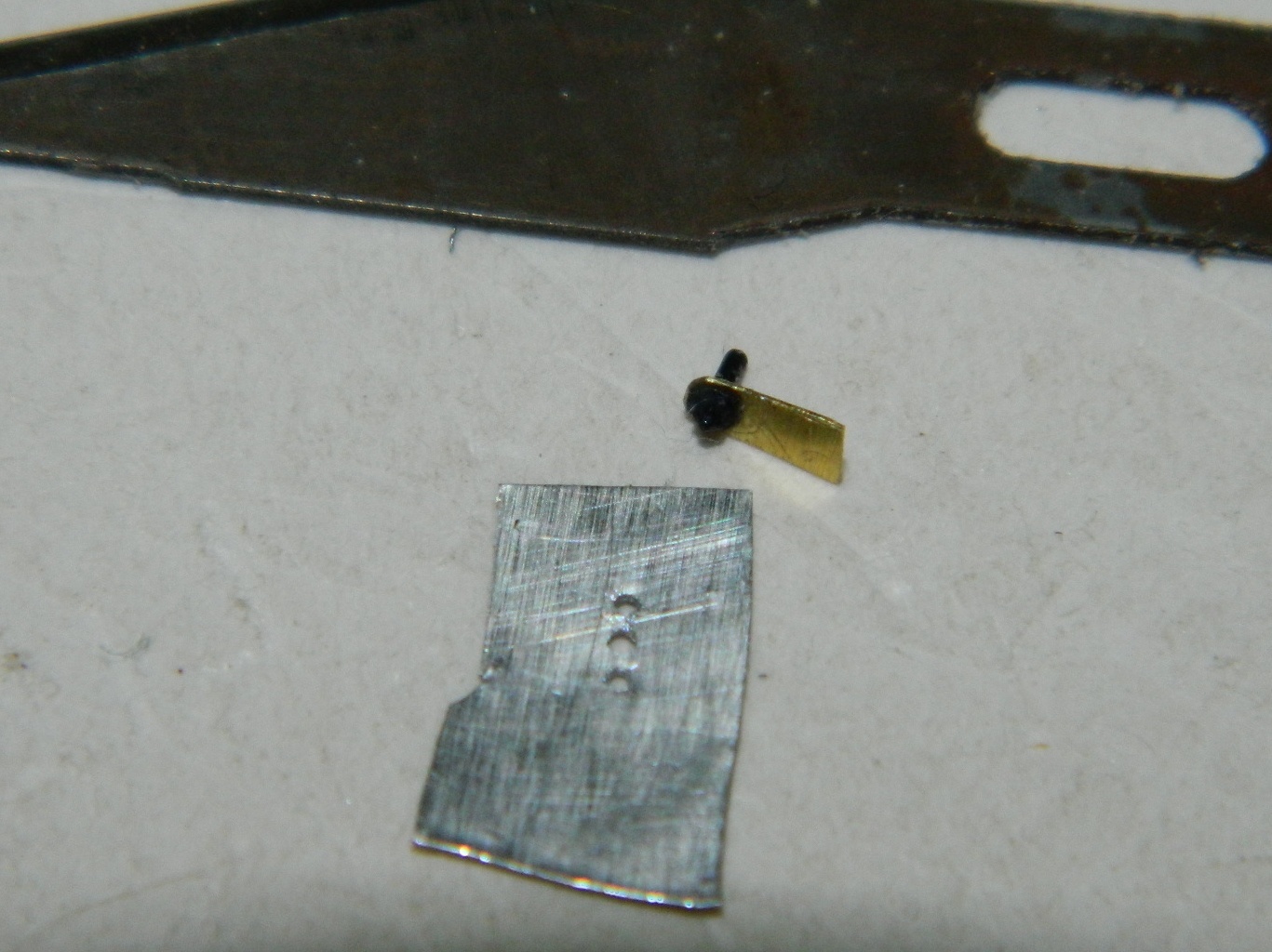
Another prominent feature that is clearly visible is the throttle linkage. Since the AM set didn’t provide one, it was necessary to make one. The first piece I made, which is the pivot for two linkage arms, I made out of heavy gauge aluminum (cut a piece out of a disposable aluminum roasting pan). But being aluminum, it bent FAR too easily so I decided to use brass instead, cutting a piece from the fretting of photo-etched detail parts, some of which I’ll be using later on:

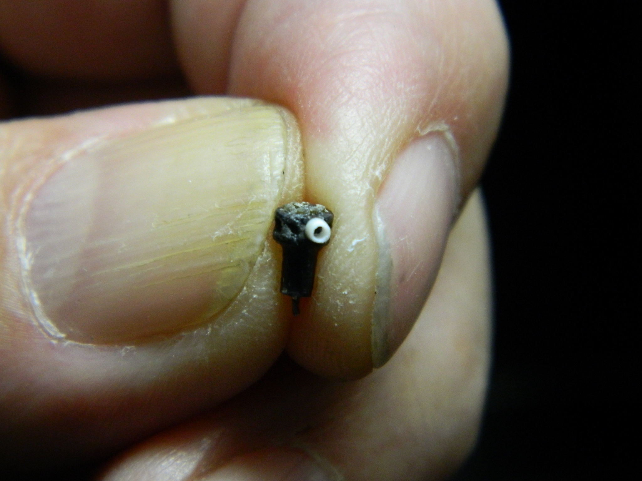
Since they wouldn’t be structural and are easier to cut, I took another piece of aluminum from that pan to make some of the linkage bits. I realized that it would be MUCH easier to drill the holes I needed first and then trim the aluminum accordingly (it took me a few tries to get the holes all lined up). The bolt in the brass linkage pivot is a model railroading part from Grandt Line; REALLY FORNICATING SMALL bolts with heads:

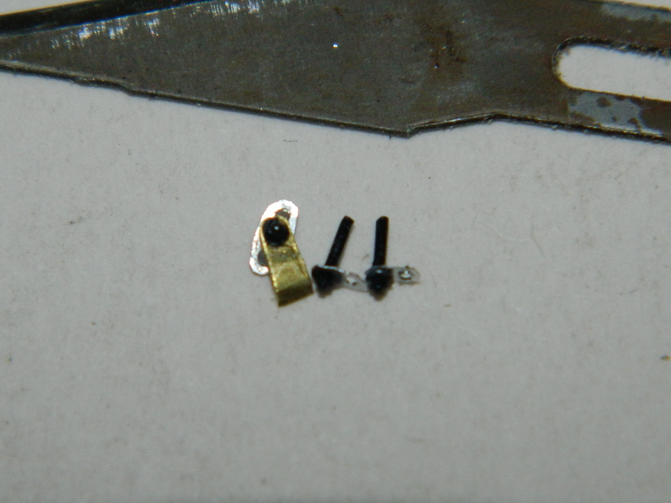
Then it was time to cut some copper wire, fabricate the linkage arms, and glue the whole thing to the engine and carburetors. The trick to using these bolts is to leave the bolt shaft on, drill a hole to accept them, and then glue them in place:
And THAT’S when I realized I was holding the engine backwards. The linkage goes on the other side! So I quickly cut and snapped off the linkage assembly and reattached it to the other side (miraculously NOT breaking anything in the process; if you ever have to remove something you’ve just used superglue to attach, the sooner you do it the better it will be because superglue gets harder over time; if you wait overnight, there will be damage) :


More fit problems. The lower back hull piece from the Verlinden AM set was cast too narrowly. The tan resin is supposed to be in contact with the dark green plastic and that will have to be fixed:
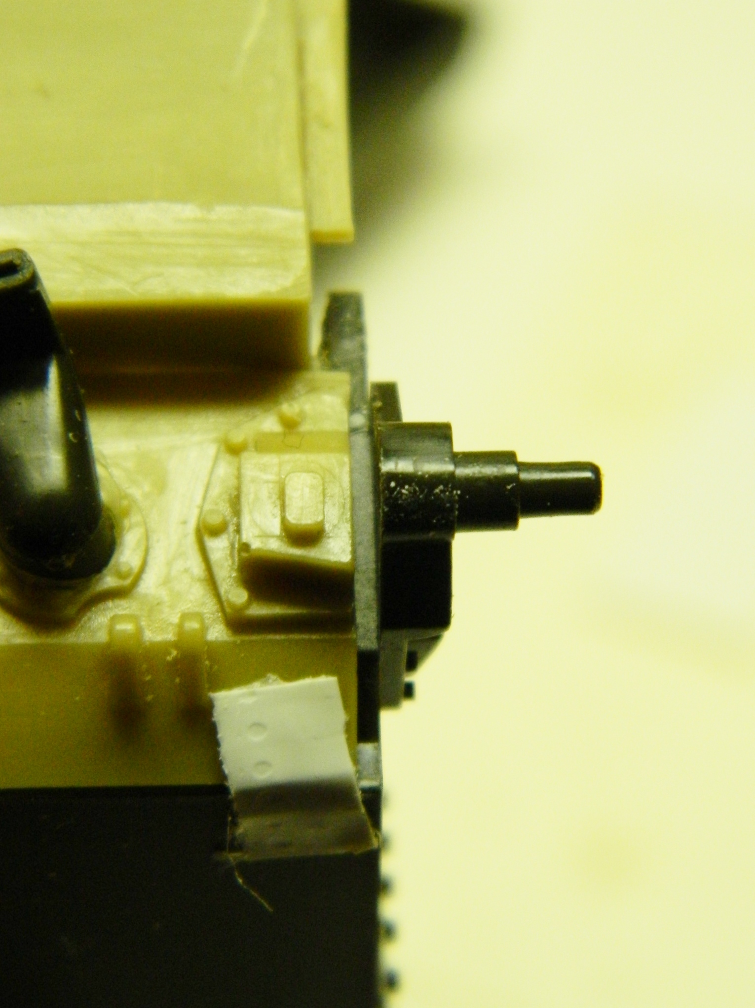
The way the resin parts fit together results in the radiator bulkhead sitting at an angle:
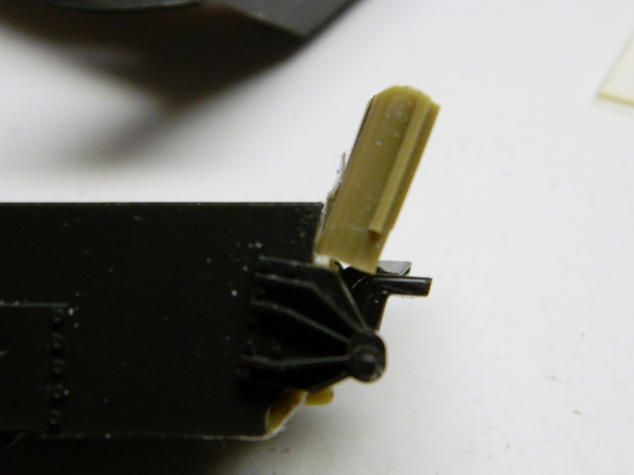
But if you look at the reference (Sherman: A History of the American Medium Tank by R.P. Hunnicutt, ISBN 0-89141-080-5, page 155), you’ll see that the radiator is supposed to be vertical (the knife tip points to the side view of the radiators):
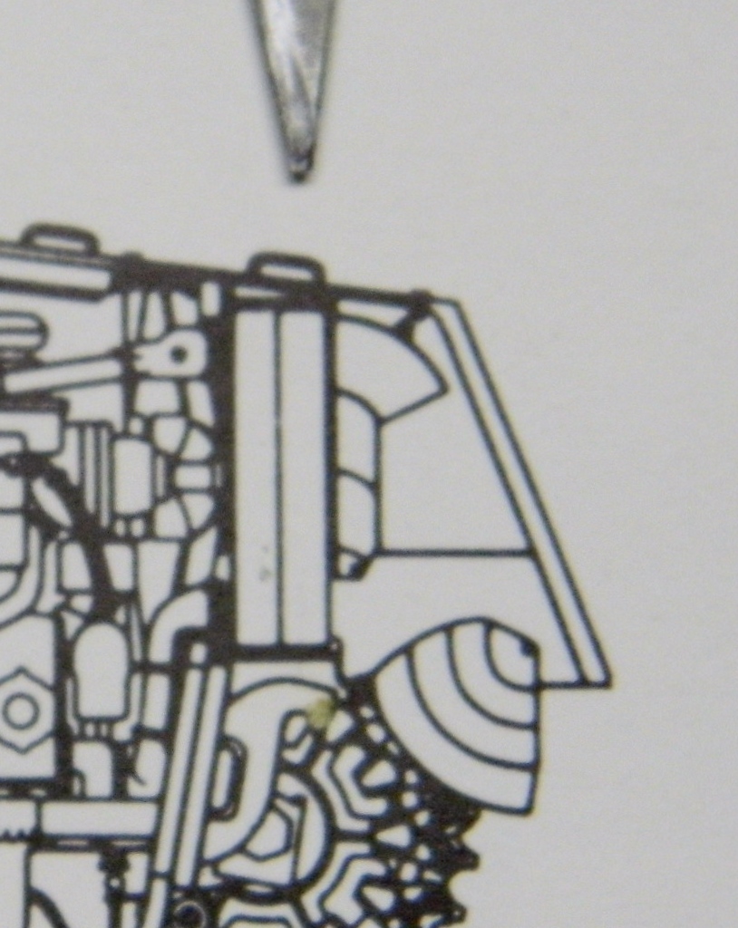
Obviously, all of those inaccuracies have to be fixed.
