My usual procedure is to start with the cockpit first so I turned my efforts in that direction.
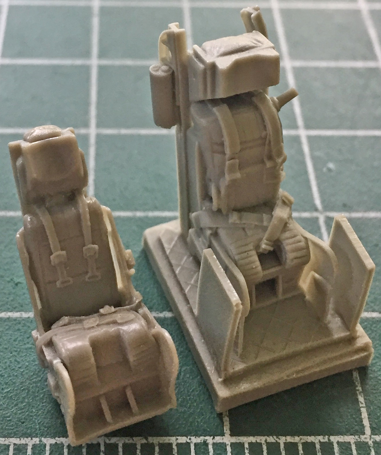
I had purchased a cockpit detail set from True Details and, totally forgetting that I had, also purchased a pair of ejection seats from Pavla Models out of the Czech Republic. My oversight ended up offering me more options. Neither of the ejections seat sets was 100% accurate, each had something the other lacked. My choice became, which of the seats’ errors/omissions would be easiest to fix? As it turned out, I’m going to use the Pavla seats (the one on the left; part of what makes them look SO different in the photo is that the True Detail seat is still attached to the pouring block and the Pavla seat isn’t):
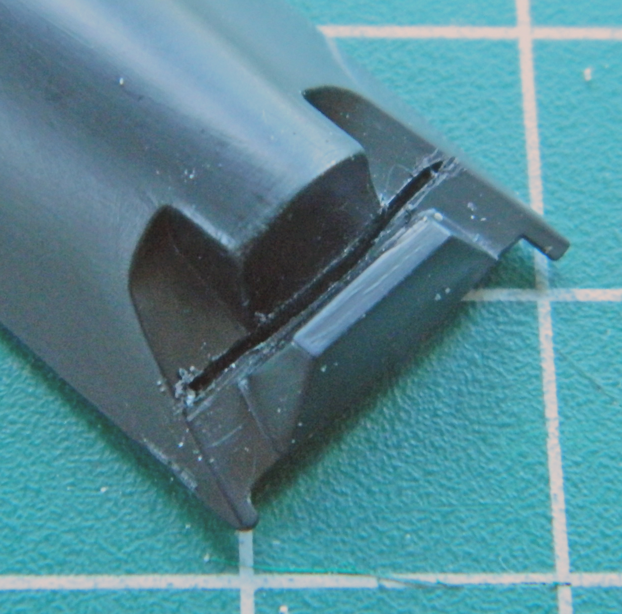
There are almost always casting flaws…it’s just the nature of the process. In this case, where the wings on the lower front portion of the seat attached were a bit off. It wasn’t well attached to the seat, as you can see by the gap:
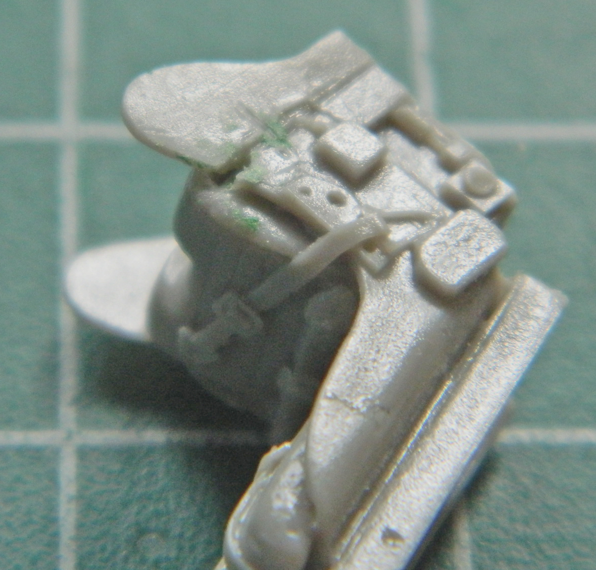
The seam where the wing attaches isn’t supposed to be there, either, but once the seats are installed in the cockpit tubs, those seams won’t be visible…but the gap at the top will be. I tried putty to see if it would adhere to this particular resin and it doesn’t. That meant I had to fill the gap with styrene and finish it to invisibility…so I did:
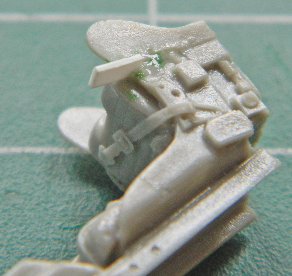
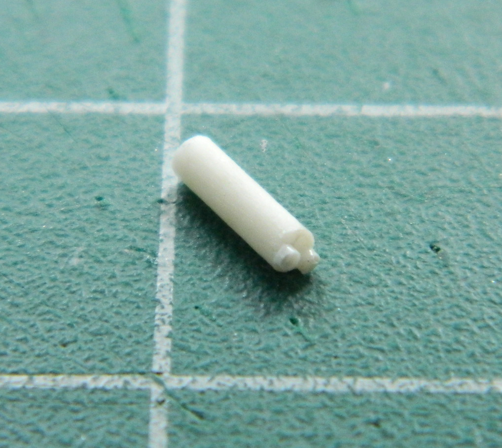
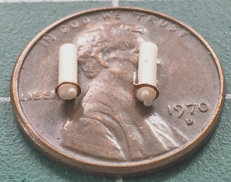
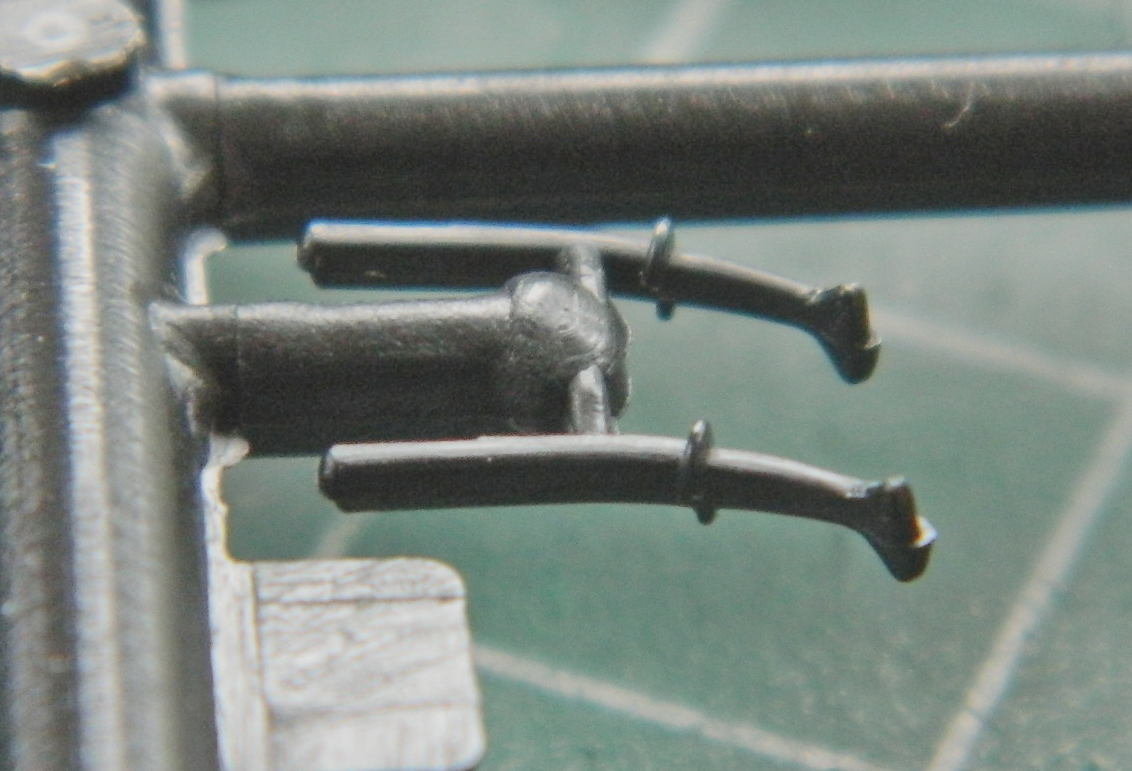
One the side near the top there is a cylindrical “thing” with two lines coming out of it. I used 1/16″ (.062″) (1.58mm) styrene rod for the body and .025″ (.635mm) styrene rod for the fittings. I used the True Details seat to determine the length of the body and then used locking tweezers on stands to align the rods and glued two pieces on:
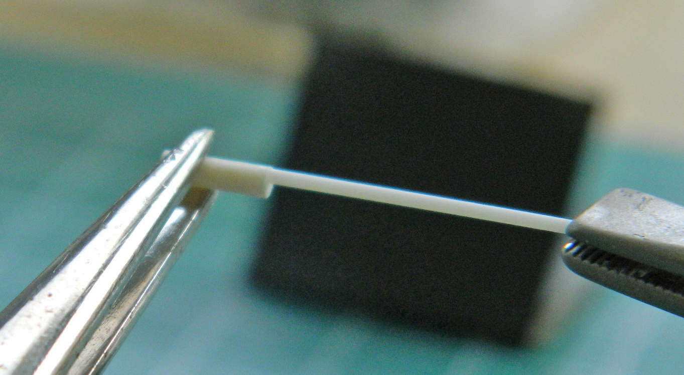
Once the glue had set, I trimmed the .025″ (.625mm) rods and center drilled them with a .0135″ (.343mm) bit:
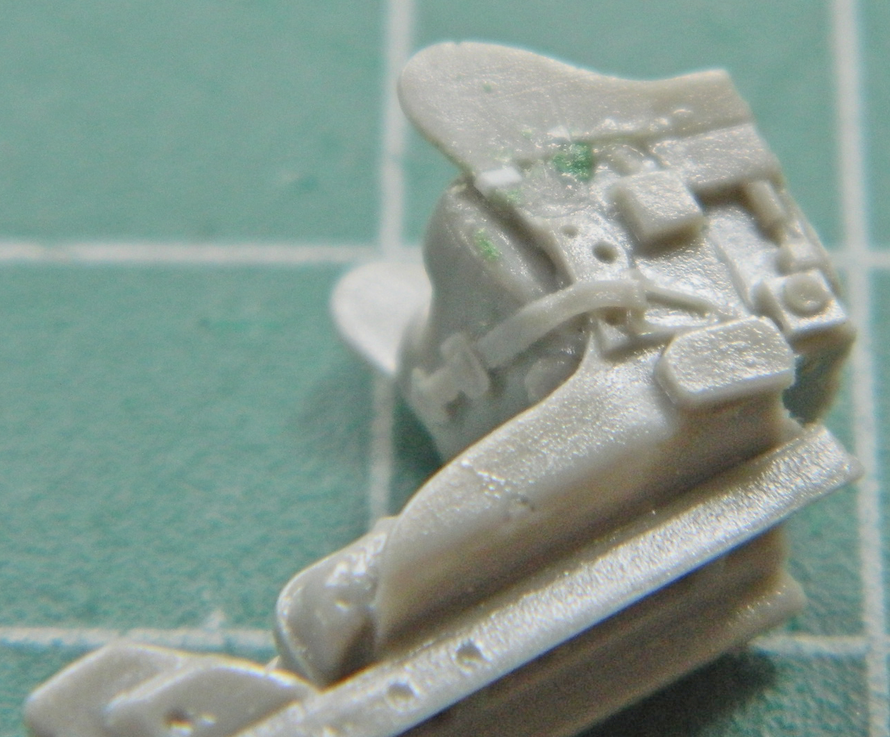
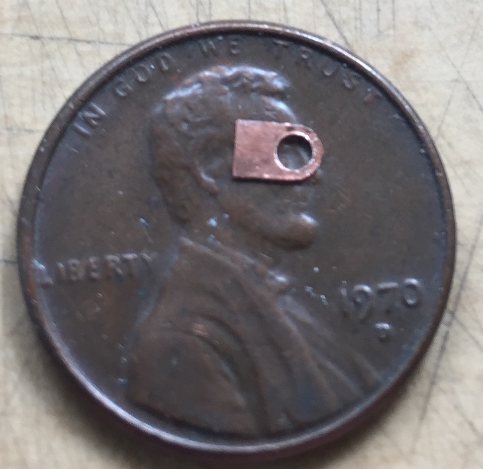
These cylinders aren’t just stuck to the frame of the seats, they have mounting brackets. I made them from .005″ (.127mm) copper shim stock and used the punch and die set to start the holes and a fine (very fine) rat-tail file to open the holes to the appropriate diameter. Tip: punch/drill the hole first, then cut to approximate size and use a file to bring the dimensions down to size:
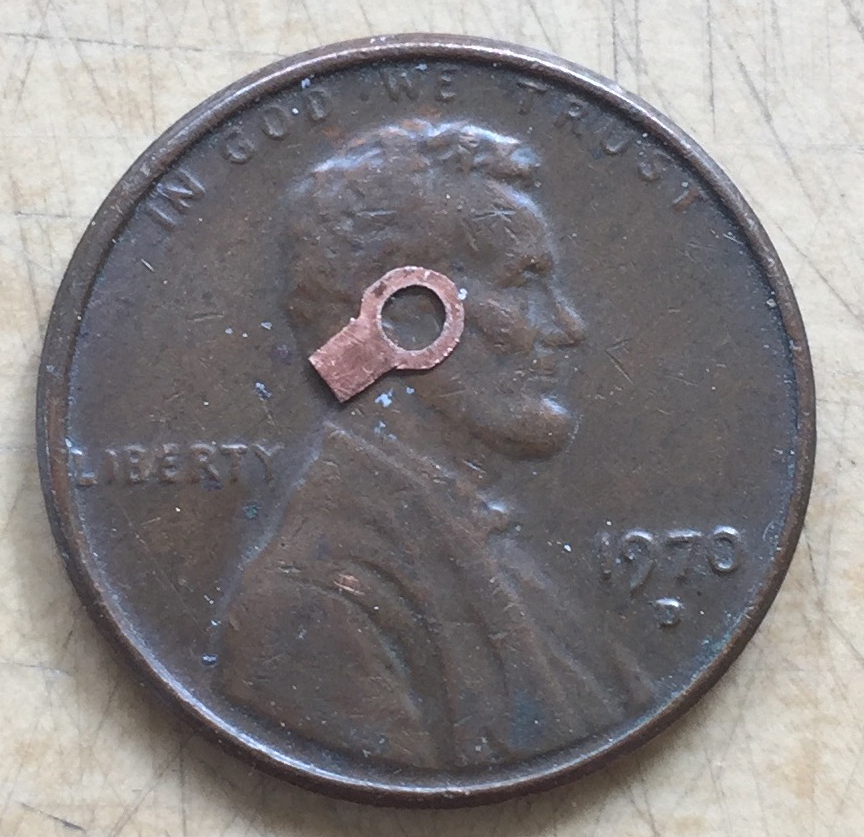
The flange is a little too large. I fixed that by holding the body of the bracket in the nose of small pliers and filed away the excess…and forgot to take pictures. (Perfection still eludes me.) With everything to their final size, I slid the bracket over the cylinder, glued it in place, and bent the mounting tab parallel to the cylinder’s body:
Even though once these parts are mounted in place and very unlikely to ever be stressed, “very unlikely” doesn’t even rhyme with “won’t ever.” I mean, it’s only .005″ (.127mm) copper! So I took a piece of .010″ (.254mm) styrene scrap and added additional support at the bottom of the cylinder:

Once glued in place, the .010″ (.254mm) styrene support isn’t easily visible and paint should make it even less visible. I didn’t use the True Detail seats to determine the location of these parts, I used reference photos. Once glued into position, I added .010″ (.254mm) solder lines, routed them down behind the seats, and ended up with two of this:

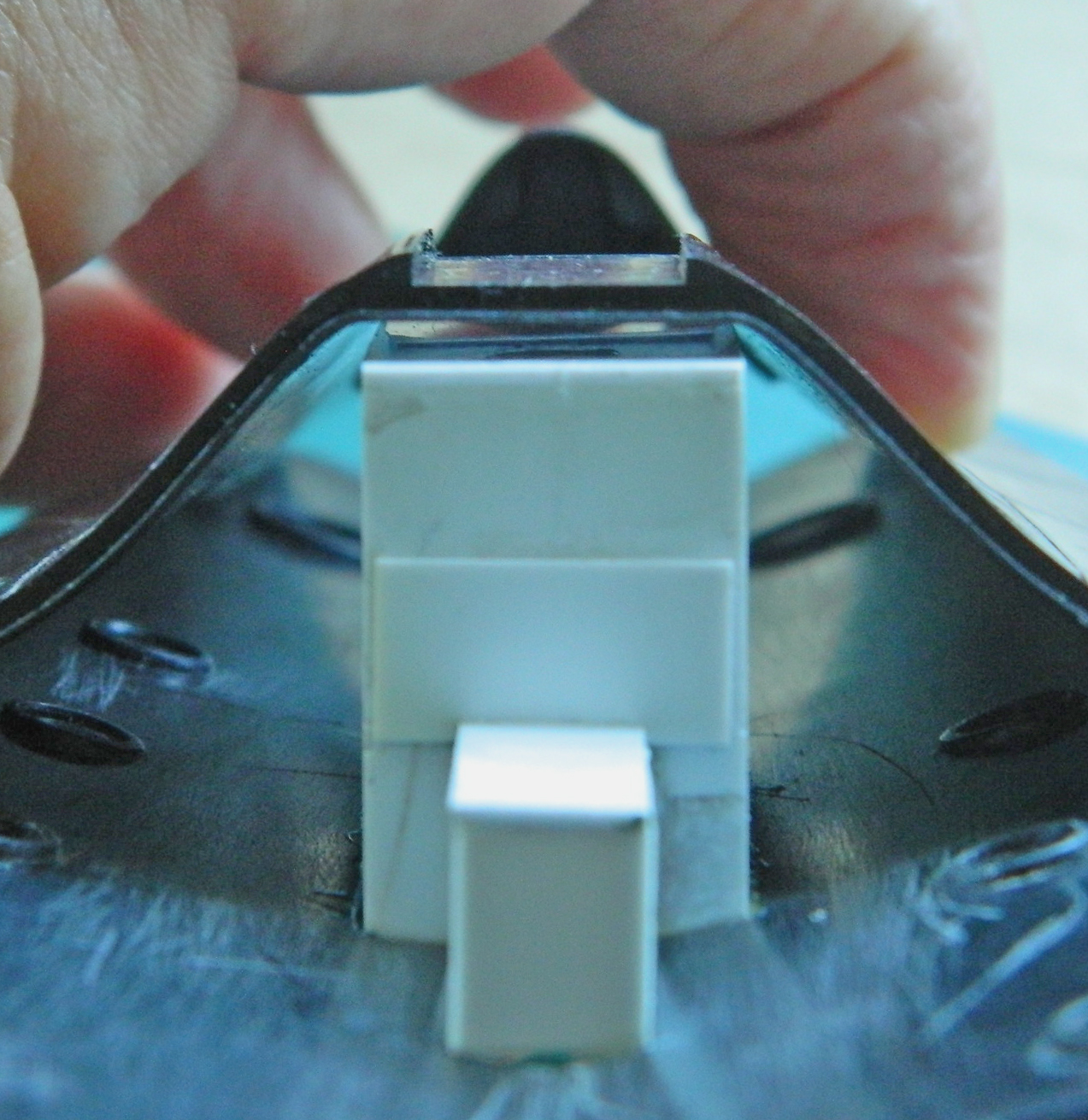
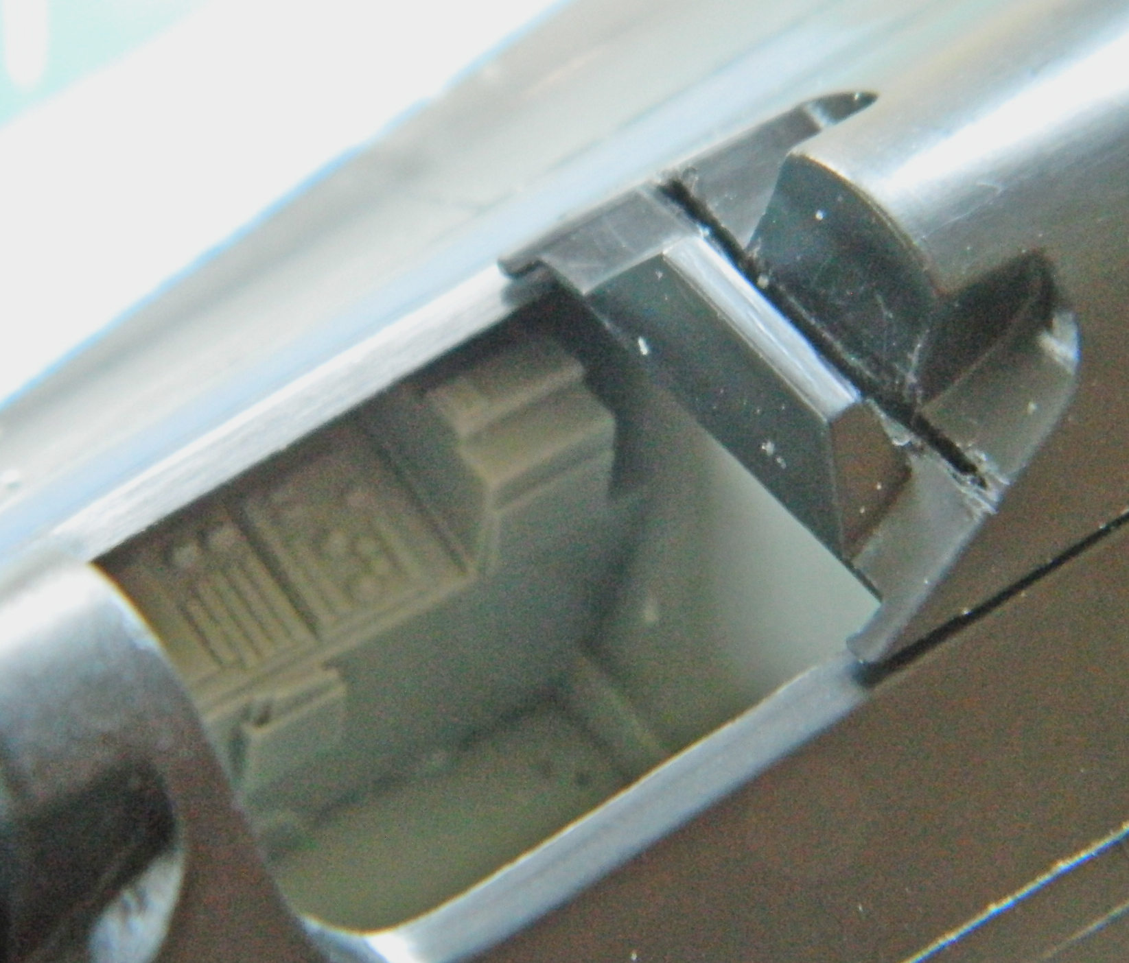
ONLY THEN did it occur to me that maybe I should perhaps check to see if the nose wheel bay EVEN FREAKING FIT into the fuselage! So I used white glue to hold the bay’s box in position and used the under fuselage section to see if maybe IT WOULD FREAKING FIT. In so doing, the first thing I noticed is the gap I’m going to have to deal with during assembly (that, of course, is on both sides and I sincerely doubt it’s the only gap):

I’ll pay the toll on that bridge when I get there. The reason I’m doing this is to see if the sodding box fits inside the fuselage…and I got lucky. It does:
Okay…dodged that falling piano! So while I’m here, let’s see if the resin cockpit tubs FREAKING FIT:
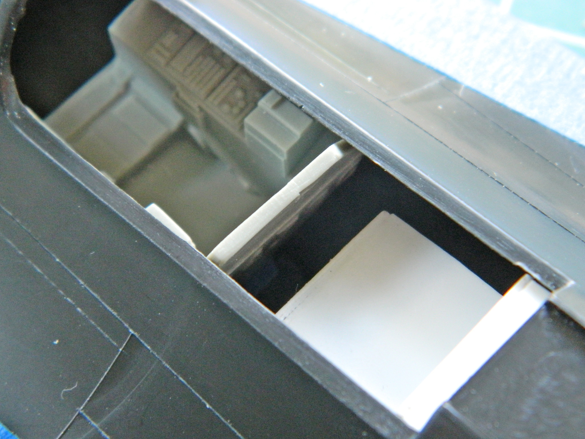
Whew…two for two.
Okay, since that fits, I checked the fit of the fuselage top behind the rear cockpit…and noticed that the fit problems seem to be consistent (and note the depression in the surface of the fuselage at the upper right…there’s several places where this happens and they’ll get filled with putty):
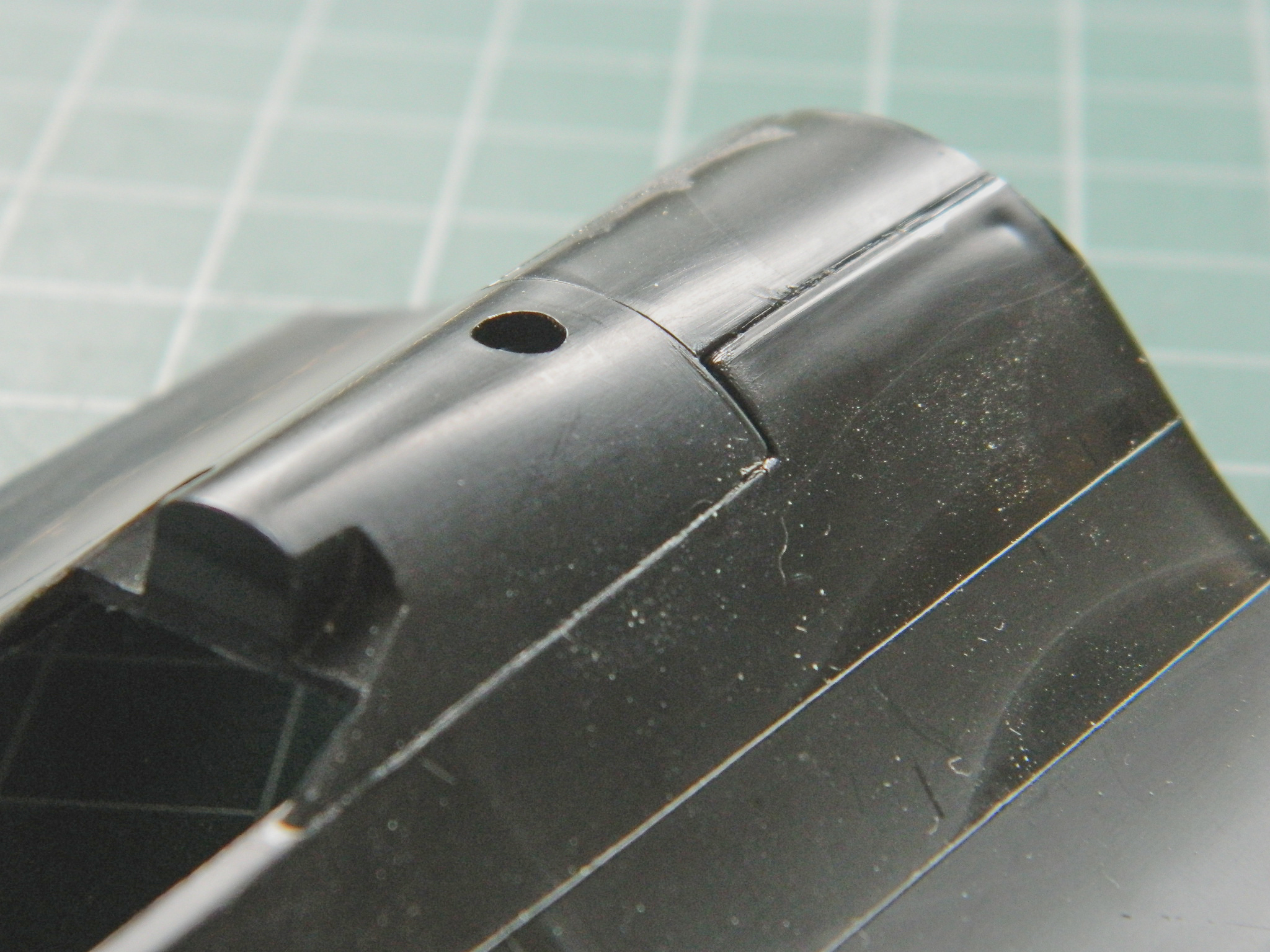
I knew I was going to have to trim the kit’s rear cockpit opening back a bit to fit the cockpit tub (you can see in the next photo where I have already started cutting it away) (and if you look at the above photo, it’s already been removed):
I treated the front cockpit the same way.
I checked the fit of the RSO’s instrument panel and saw that I needed to trim the plastic so that the panel fit better…or at all:

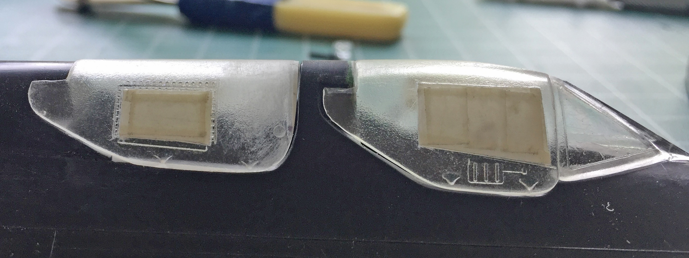
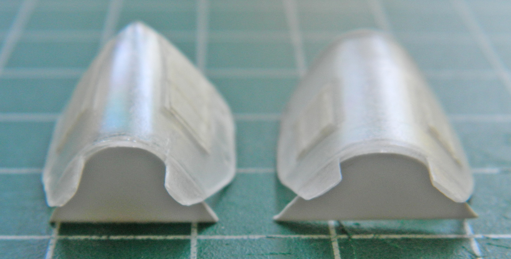
While I was checking fit, and not remotely expecting that anything would fit, I checked how the canopies fit the fuselage. They don’t very well:


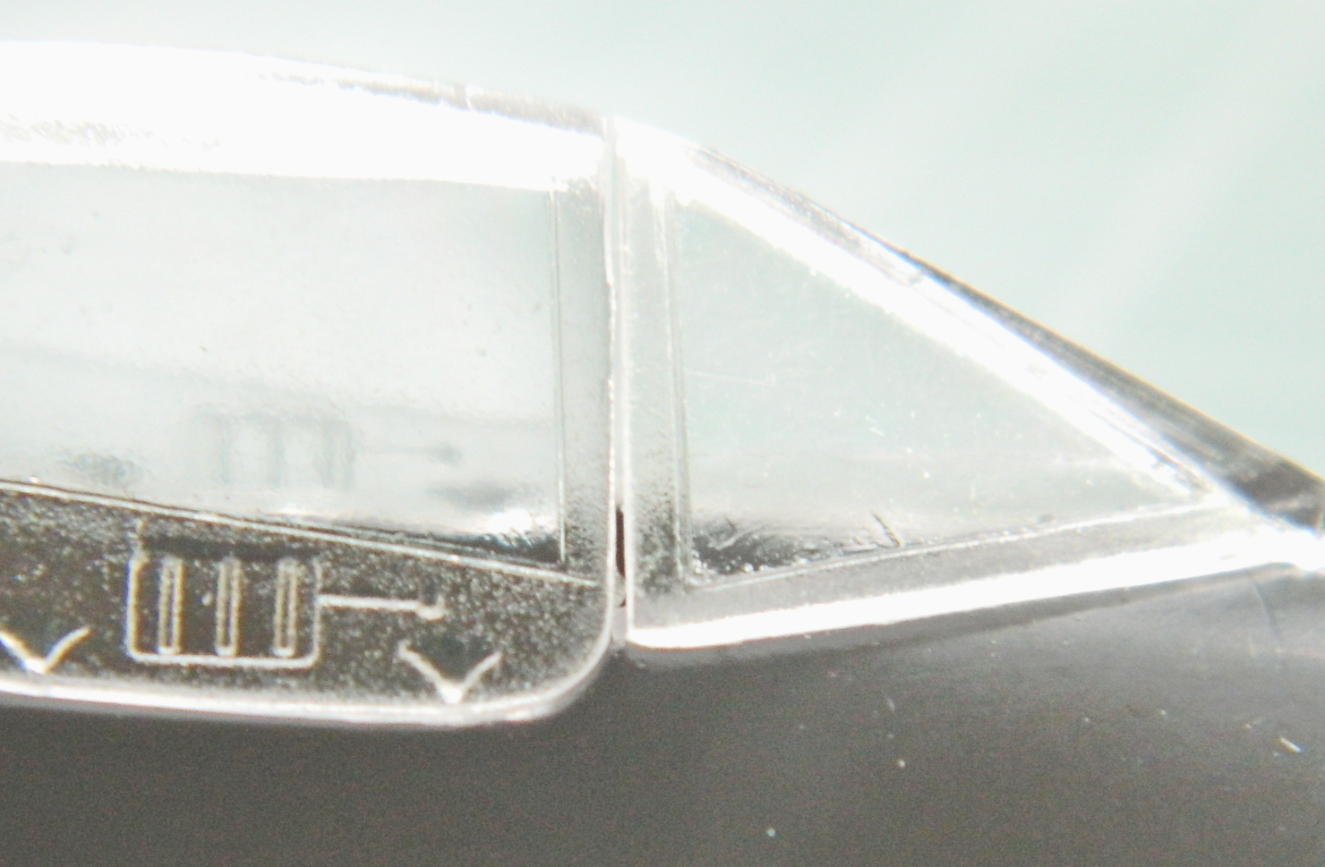
Even though the model with be displayed with the canopies open and fit isn’t really critical, I will be using the canopies to mask the cockpits when it comes time to throw paint onto this thing. I’ve learned that using large globs of white glue to seal things doesn’t do good things for the final paint job when they’re removed. It will take too much paint away with it. It makes more sense to put the time/effort into a good fit at the front of the job rather than try to recover a paint job at the back of the job.
So I added plastic to the fuselage and fiddled and sanded until the fit was better. I also added .020″ (.508mm) plastic to the canopies because the gap was SO large (I also added plastic to the fuselage and puttied the back of the area to sharpen the edge of the fuselage):
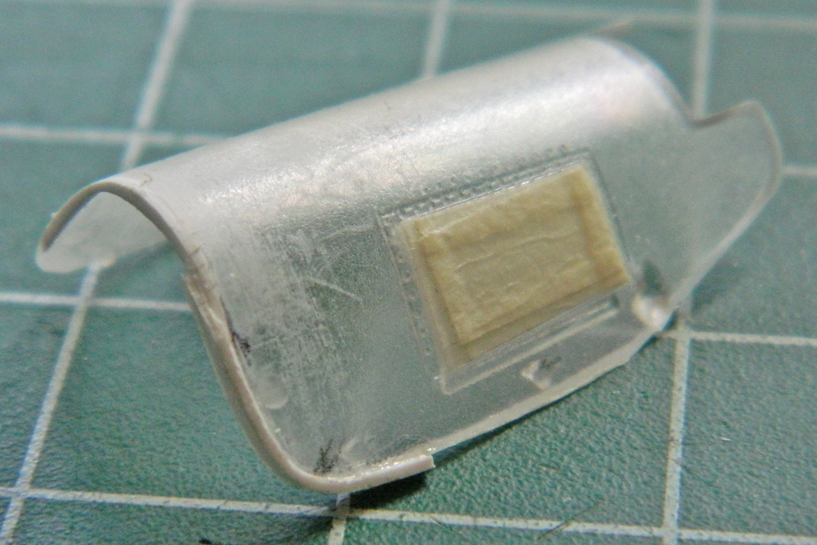

Yes…there are still gaps. If I were going to pose the canopies closed, I would have spent more time making the fit tighter. But I’m not and these gaps should easily fill with white glue and not rape the paint (too much) when they’re removed (the areas that have to remain clear were masked off to protect the surfaces from scratches):
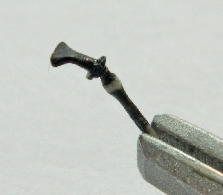
Keeping with the cockpits, I checked the kit’s pilot’s joystick against references:
The ridge to the right isn’t supposed to be there; the mold was misaligned. The shaft of the joystick is too large, the grip area is too long, and there is a bulge just below the hand rest that’s missing. I started by taking out the misaligned parting lines:

The only thing left to do is to add the four buttons (three on the top facing the pilot, one on the other side), but I’ll do that when next I’m in the mood for extremely tiny things (right after my medications are adjusted). The grip has been shortened, the bulge added, and the main shaft replaced with styrene rod:
The rudder pedals are elevated onto a platform. References show that there are ramps in front of the platform that the resin part doesn’t have. Now it does:

There are pronounced structures inside the canopies that the kit’s parts don’t have. They’re necessary to have them so that started with a job that I REALLY can’t stand…putting a bulkhead inside a curve. Tedious. Tedious. Tedious. But they’re not going to add themselves, so:
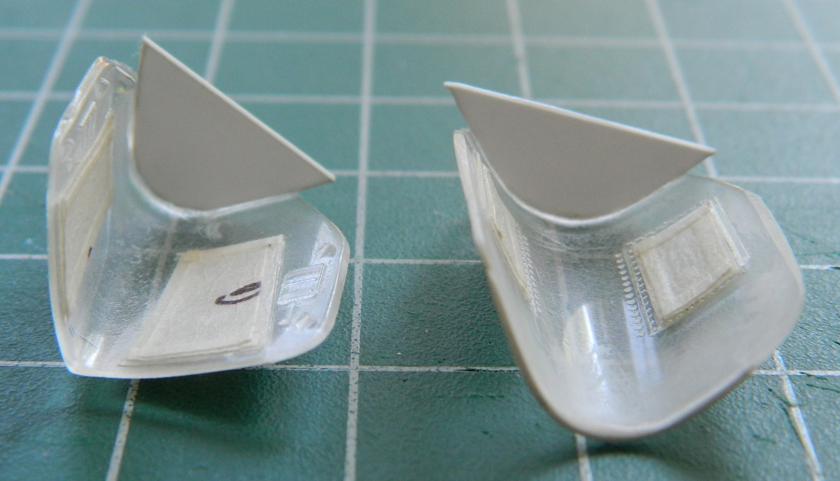
Once the glue cured overnight I removed the sections of the bulkheads that extend below the canopies’ edges.
The next trick is to add all the structure inside the canopies…
