Having already done a later Sherman variant, I wanted to work on the variant that started the lineage, an M4. This is the kit I’m starting with (and I’ll get to why another old Tamiya kit shortly):

This is the typical Tamiya Sherman from the mid 90s. It lacks sponson bottoms, the grab handles are cast as fins, the welds are recessed instead of raised seams, and all the silliness Tamiya was known for back then. Instead of going the AM route for this build, I’m using this kit as the starting point because much of it won’t make it out of the box. As an indicator of that, compare the photo above with the box contents and then look at some of these (as well as a some of the parts I’d shown in the previous post that I’d copied):

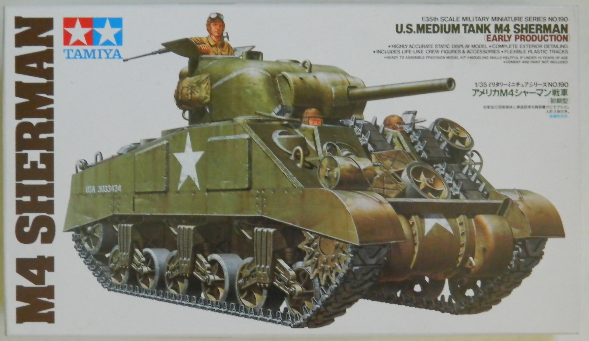
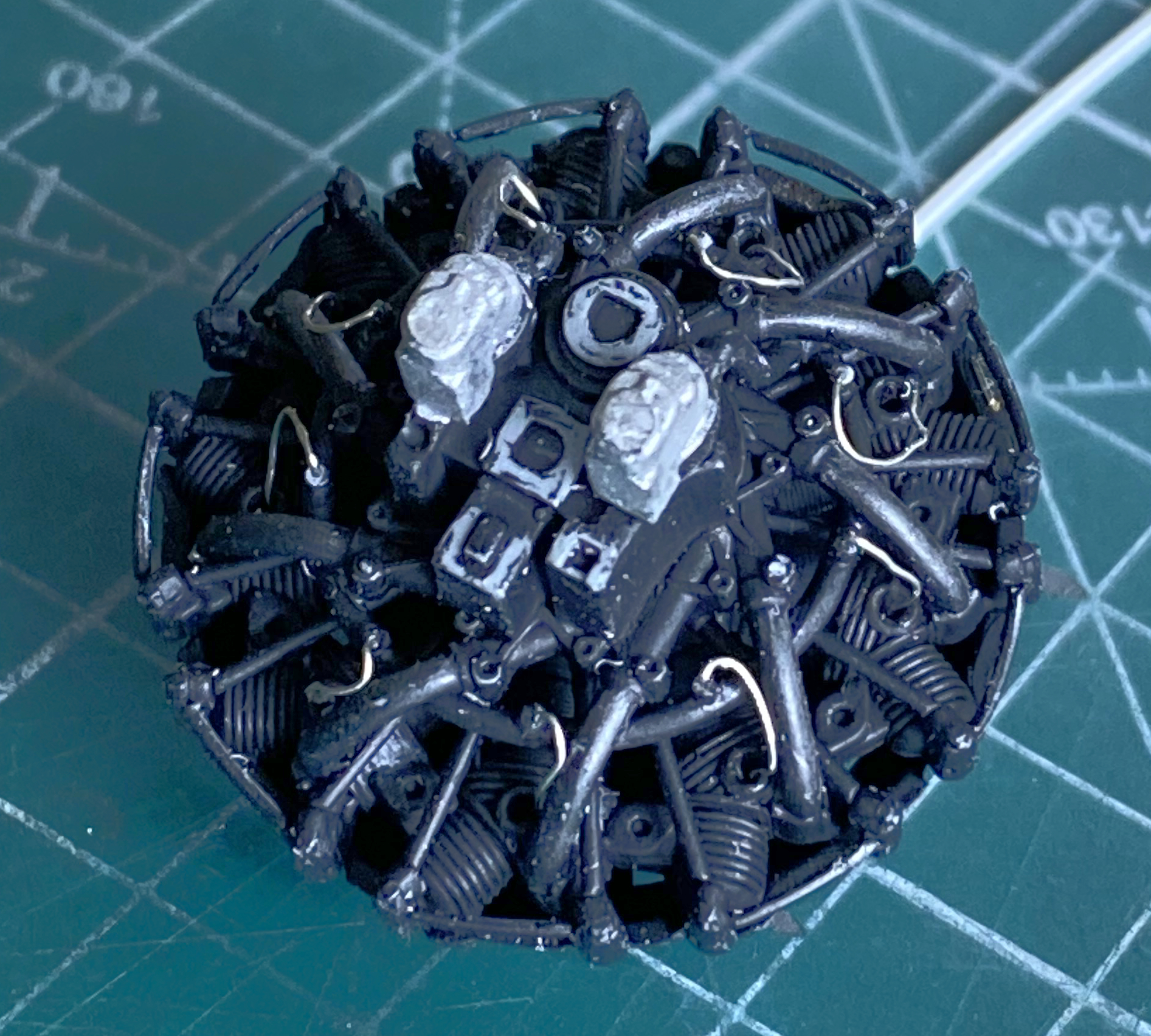
As you saw in the previous post, I’m doing a full interior. What I don’t think I got into in the last post is that I’m also doing an engine for it and using MiniArt’s R975:

Since the M3 Lee I’d started has become a shelf-queen, I’m going to use the engine I’d built for that build in this one:
The detail of CMK’s AM set is impressive and I think it would be a shame to hide all those nicely done parts inside where most of the details can’t be seen. I had briefly considered doing a cutaway model but I live with this critter:

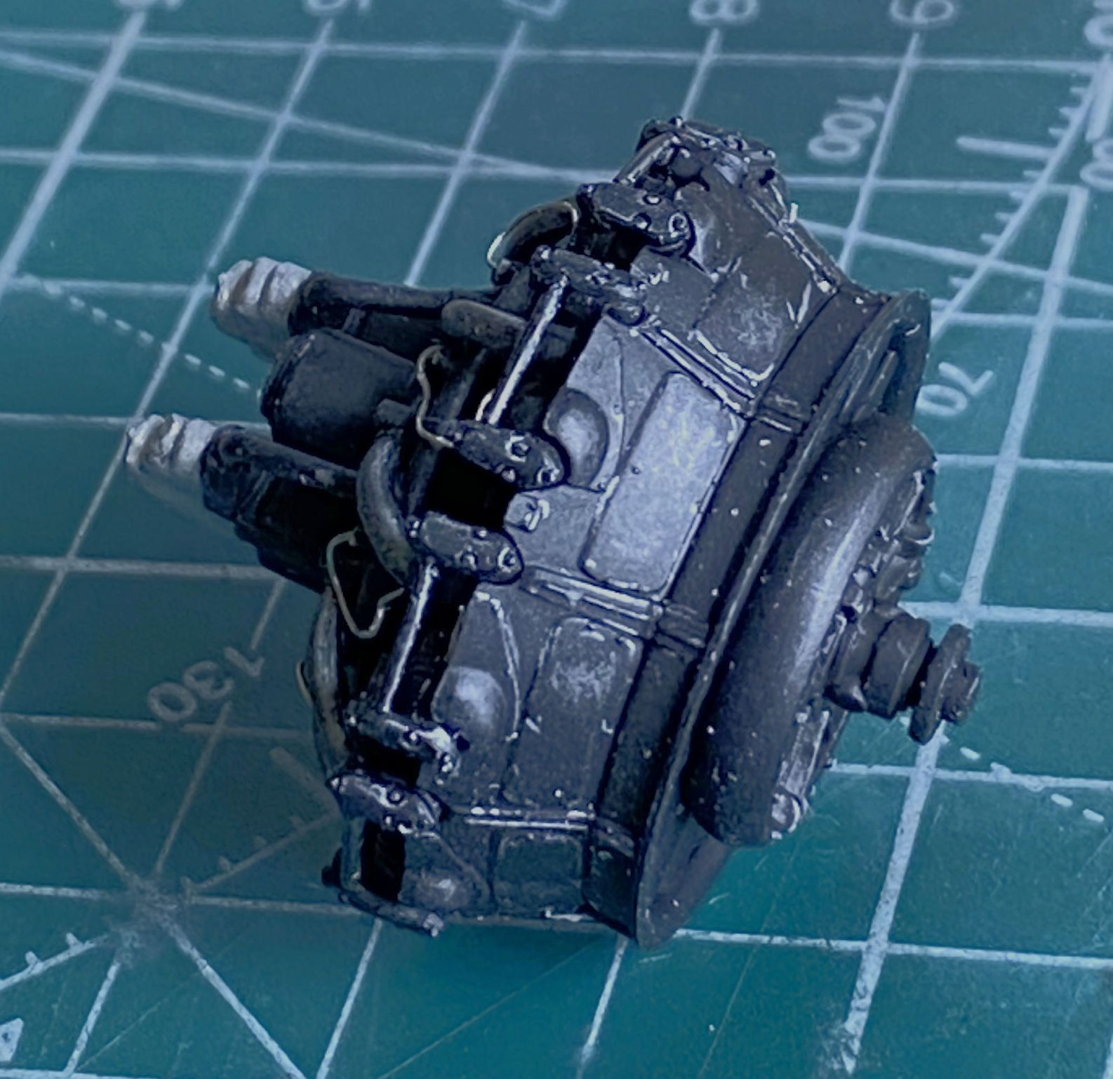
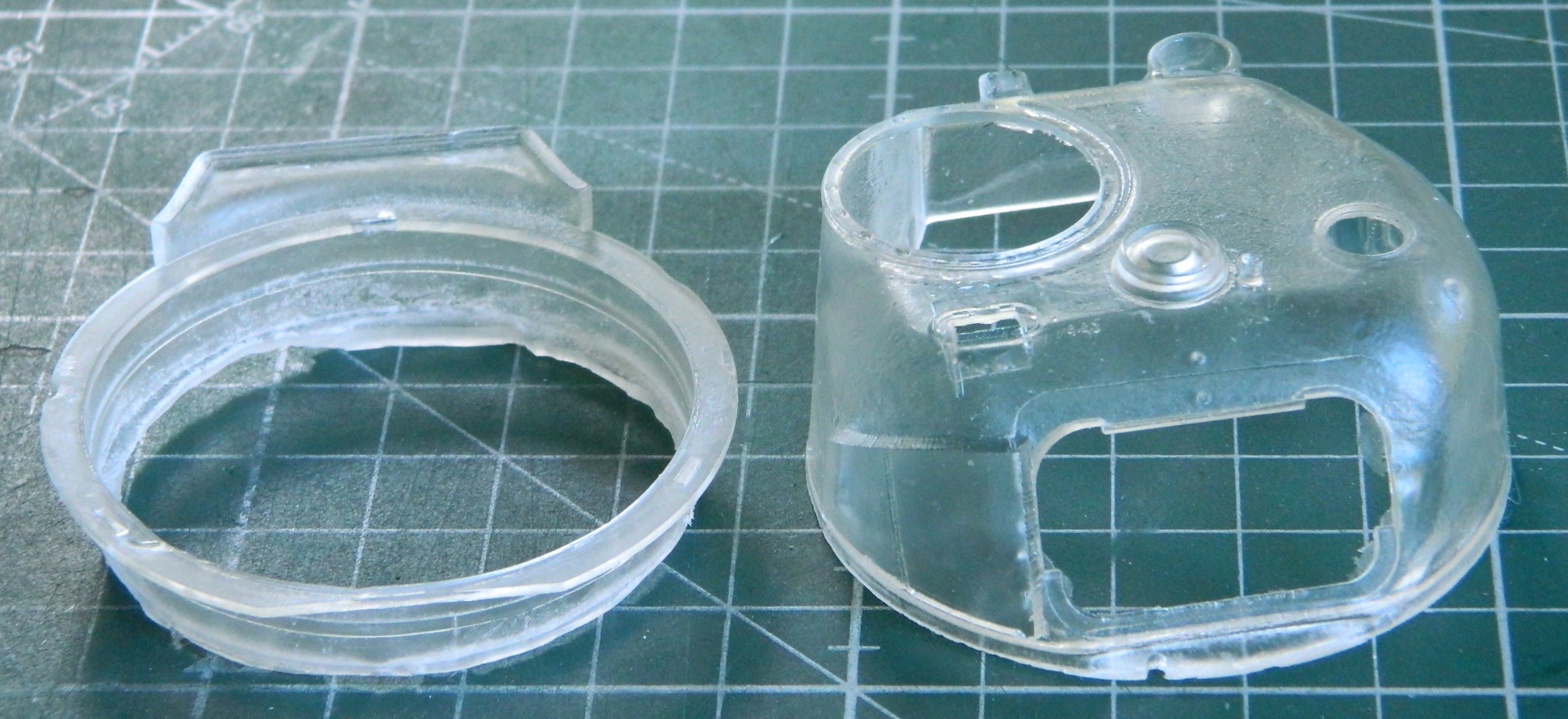
She is a cat hair factory and is very giving. I do NOT want to try to get cat hair out of a cutaway model. Instead, I’m going to replace a side panel of the upper hull with clear styrene and to make creating a clear panel for the curved turret SO much easier, I’ll be using this instead of the Tamiya turret that I special-ordered from TMD (who is, I’m sad to say, closing their doors at the end of 2022…so if you want something they offer, get them now because the clock is running out):
I will be using Panda Plastic’s tracks again because they’re just easy to work with and fit well. I’ll also be using a bunch of other items from TMD, Resicast (okay…not “a bunch” because though they produce an excellent product, their prices are steep), some old Verlinden bits I have laying about, and plenty of spare parts. It’s a Sherman. There will be “stuff” hanging on it.
This is going to be a Chinese-interesting build. The kit, an engine from a different kit, AM parts from four (possibly more…) vendors, and none of it is really supposed to play with each other. After having spent many weeks this summer making molds and casting resin, it’s finally time to start putting some of that resin together.
Let’s do that now, then.
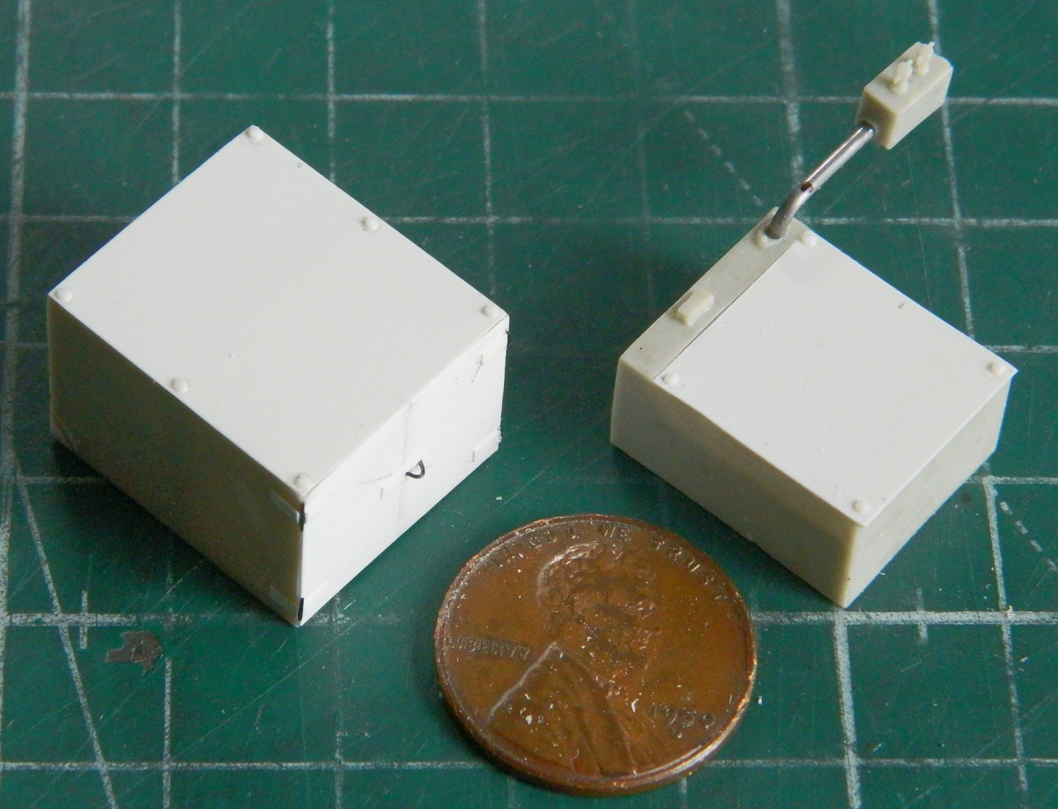
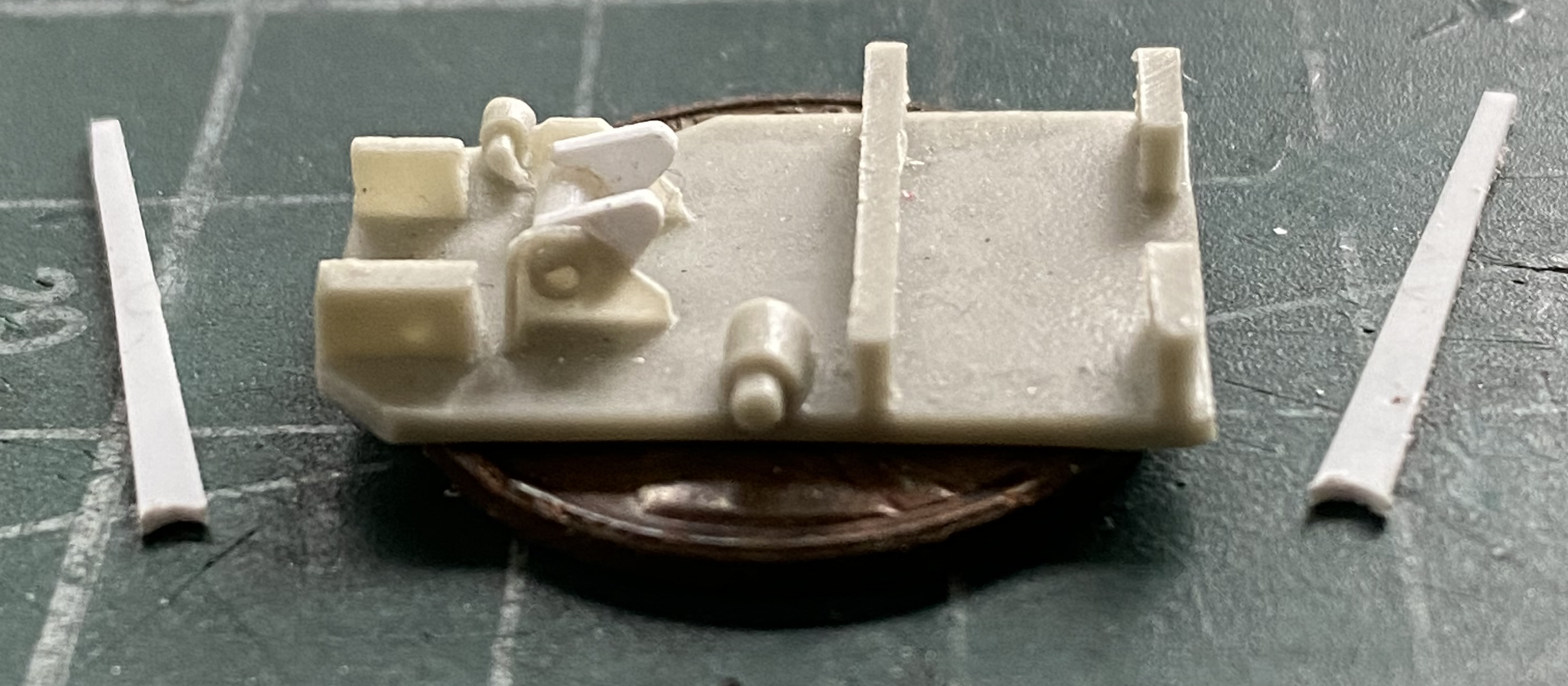
Since I’d copied the resin parts, I wanted to see if I could substitute styrene and copper shim stock (.005″ (.127mm) for the PE parts that came with the set. To see if that would work (at all), I started with a couple the boxes that populate the floor of a dry-stowage Sherman. The box to the left in the following photograph is a floor-mounted ammunition bin for the 75mm gun. The body is resin (and can be posed open to show the ammo stowed inside) and the top as well as the front doors have PE parts supplied. Instead, I used .005″ (.127mm) for the doors and hinges, with stretched sprue for the locking loop. The box to the right in the photograph is the battery box, again with a PE part that I replaced with the same thickness of styrene. Instead of using the resin conduit that comes off the battery box that the switch box hangs from, I used .040″ (1.016mm) solder:
From what I’ve read, a lot of M4s that took part in the D-Day invasion were older tanks that had been rebuilt and upgraded and I wanted to replicate one of those. These are PE/resin parts in the AM set:
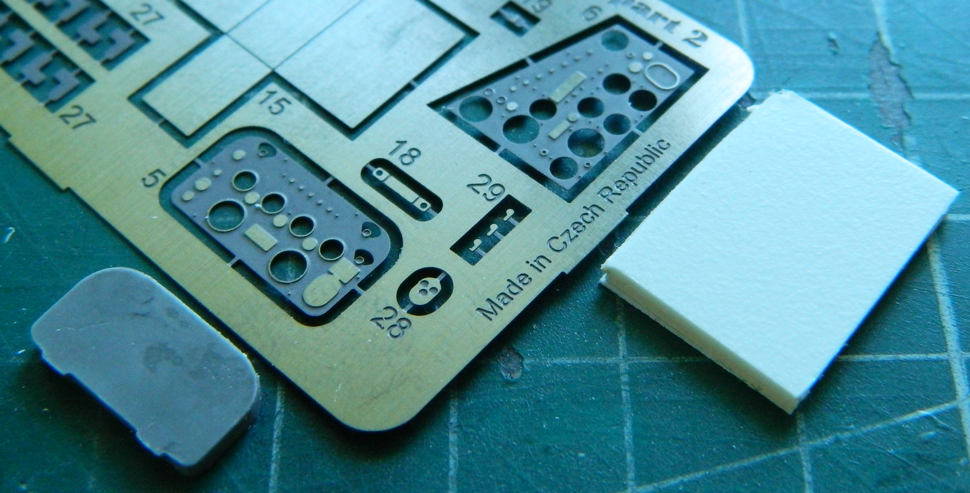
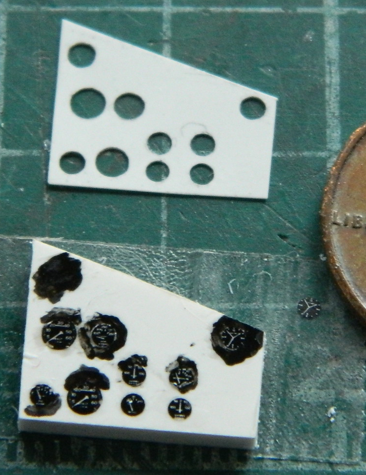
The AM set provided the PE faces for the later (left side) and earlier (right side) instrument panels. The set also provided the resin body for the instrument panel but no resin body for the earlier panel (though film gauge panels for both were supplied). Since I’m using the earlier panel, 0.060″ (1.524mm) styrene, though slightly thinner, works well for the instrument panel body.
A very handy method I’ve discovered to make straight cuts in small pieces of styrene is to use a straight-edge razor blade and a hammer (anyone who thinks force has never solved anything has obviously not built anything):
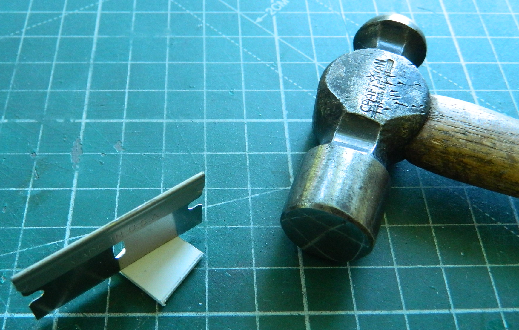
Works well, eh?:
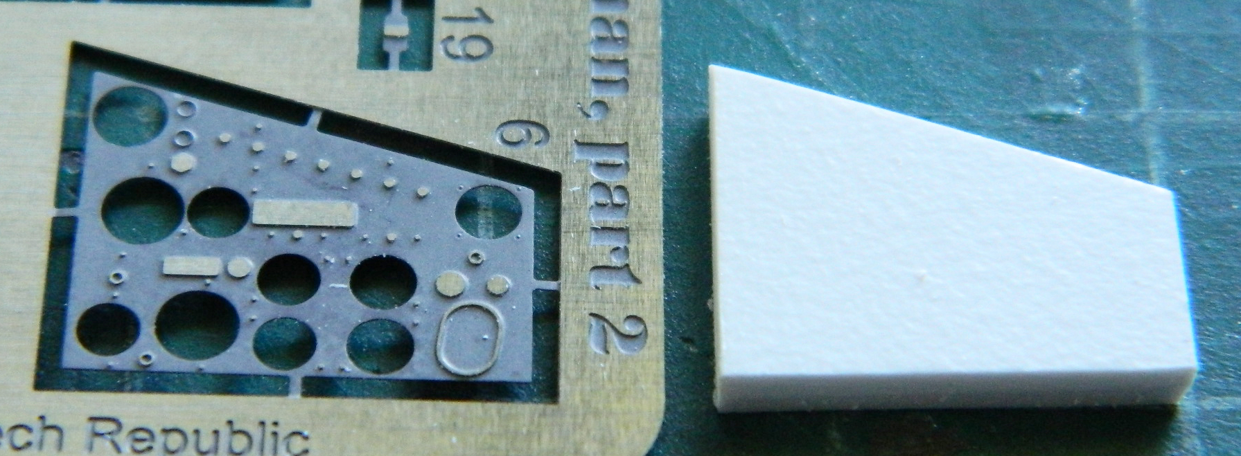
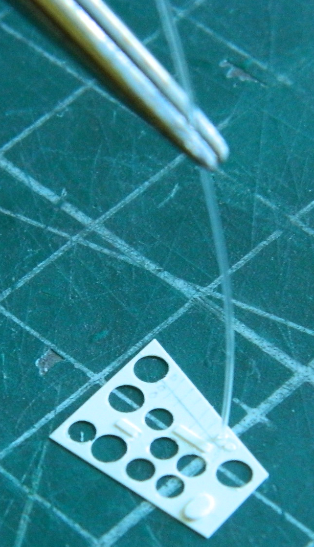
I certainly thought so. I used the PE panel to trace its outline onto a piece of .005″ (.127mm) styrene and used my punch/die set to make the holes for the film instrument faces to show through:

I was so pleased with how this was going that I just started adding all the little surface details (without checking anything else…can you see It coming?):
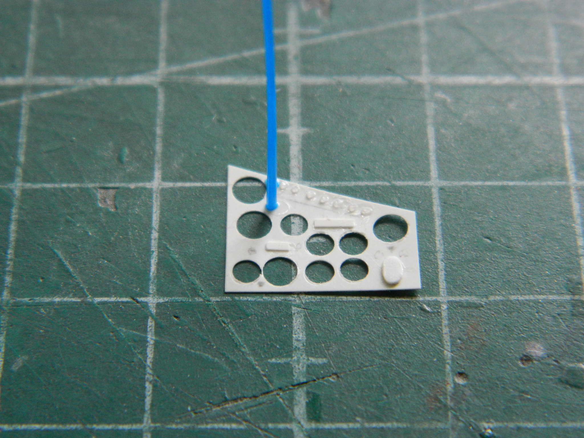
Yeah…I didn’t think so. Seeing it coming, I mean. I placed the film of the gauge faces over the body of the instrument panel and laid the face over it…and couldn’t see a damned thing. Just black dots. I went into the decal/transfer drawer and pulled out Archer’s (no longer available) US instrument faces out and realized that the holes I’d punched into the face of the panel were just way too large.
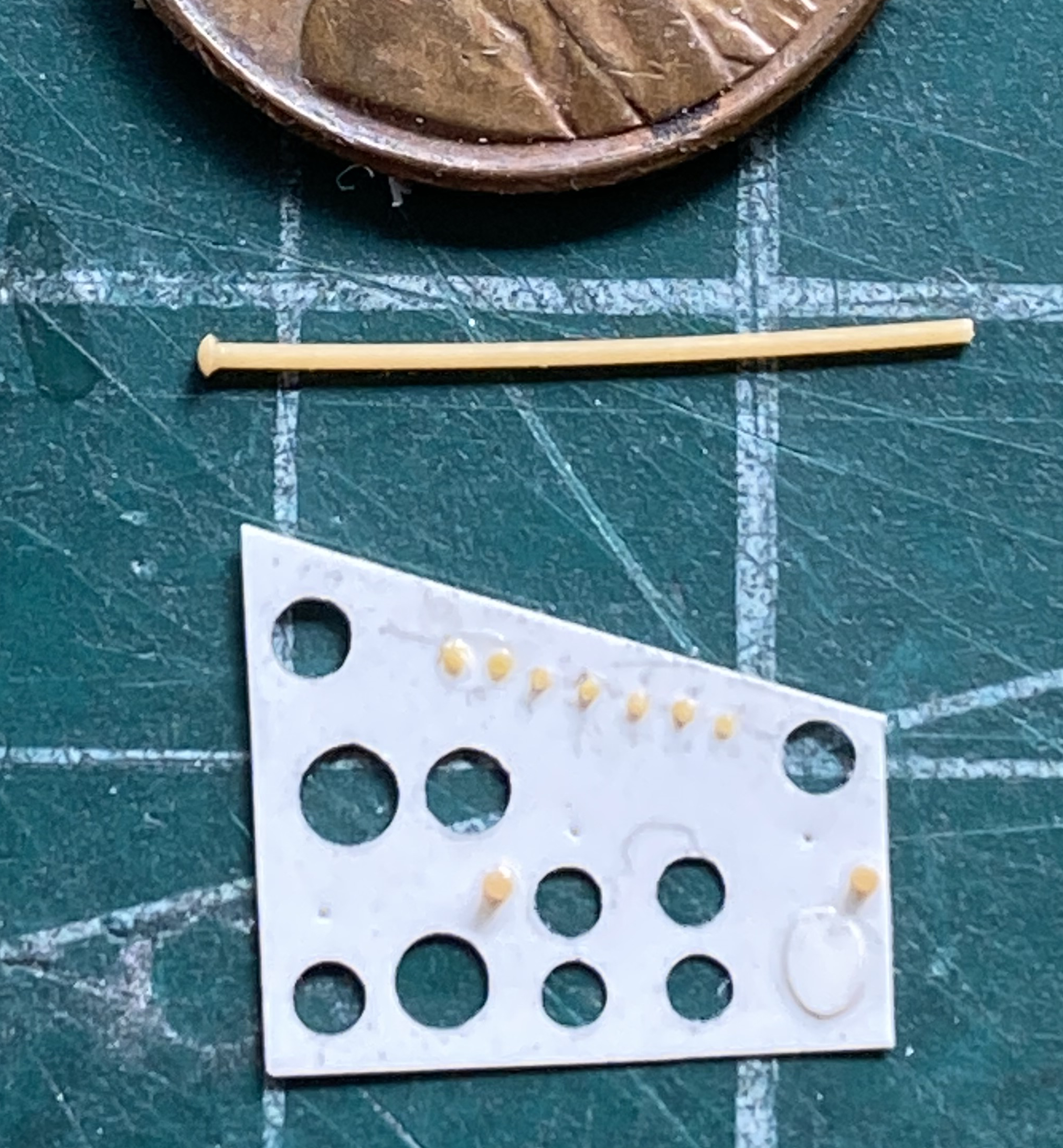
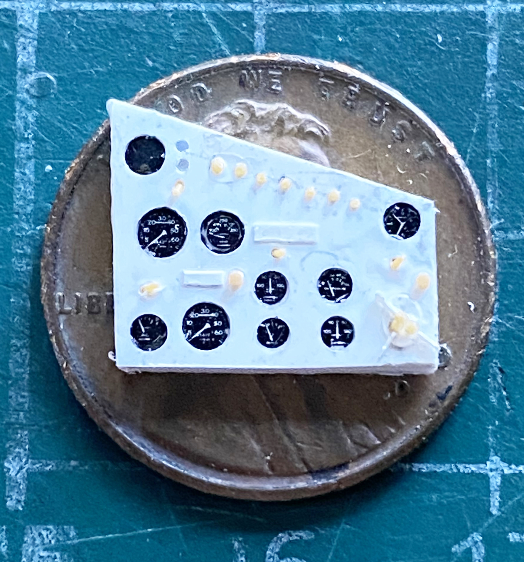
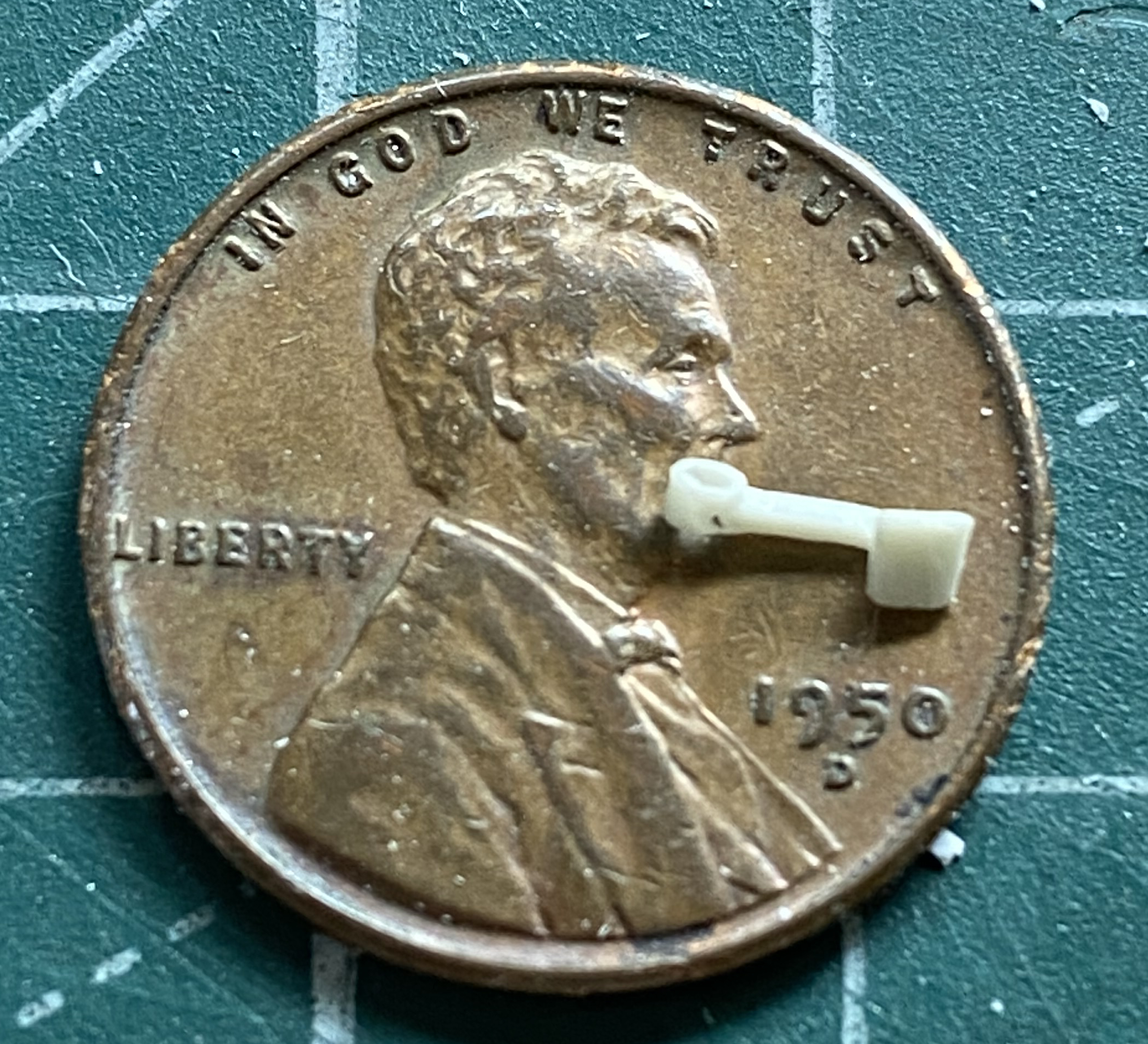
So I did the whole sodding thing again, only this time I measured things first AND did something really wild. I consulted Cunningham’s book on the Sherman. That bit of tomfoolery enabled me to get the correct gauges in the correct places and all of the correct size and that also included the correct switches (the tan part between the panel and the penny is a section of stretched sprue that I did an Icarus with by bringing it slowly towards a candle to mushroom one end…it looks like there’s a manual fuel priming pump on the panel face):
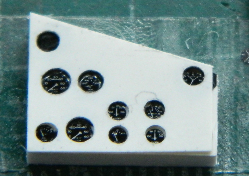
It is VERY difficult for me to get all the gauges exactly where they need to be so if they’re close enough, I check to see where white is showing that shouldn’t be and lay in a bit of flat black to hide my imperfection(s):
It all ends up working. Eventually:
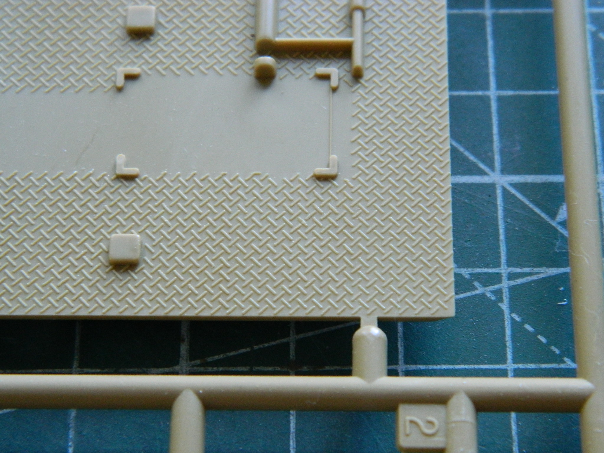
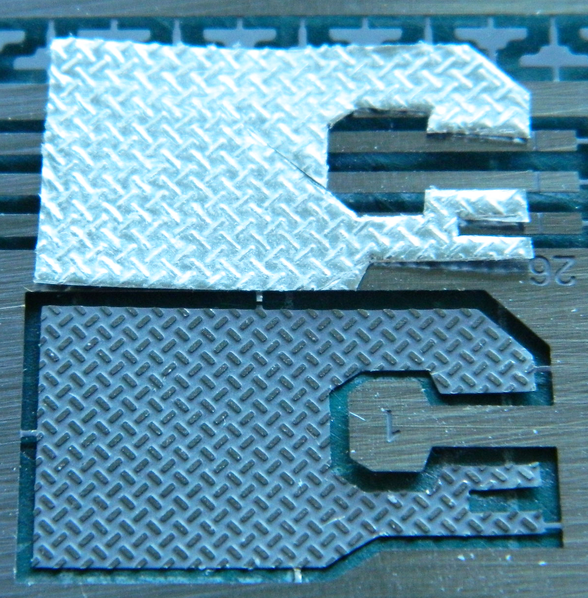
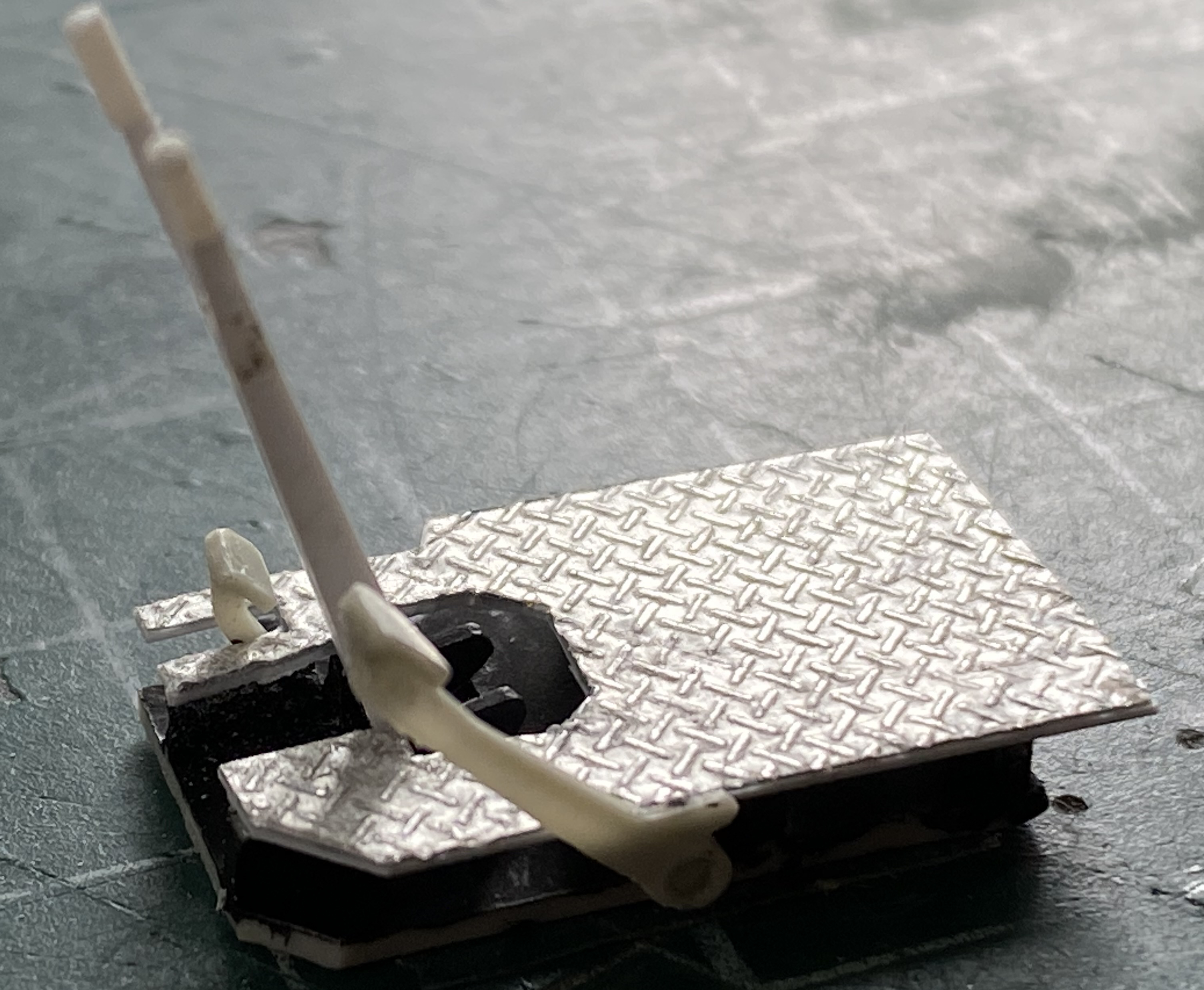
I turned my attention to the driver’s position. The floor is raised above the bottom of the hull and the part the AM set supplied was diamond-tread PE. Rather than use the PE, I copied a section of plastic diamond tread floor that is supplied with Academy’s M3 Stuart kit. I used the aluminum foil that scalpel blades are packed in, folded it over the edge of the Academy kit’s floor, and embossed the tread pattern into it. The PE part:

The Academy M3 Stuart floor:
And the aluminum foil after being embossed with the tread pattern:
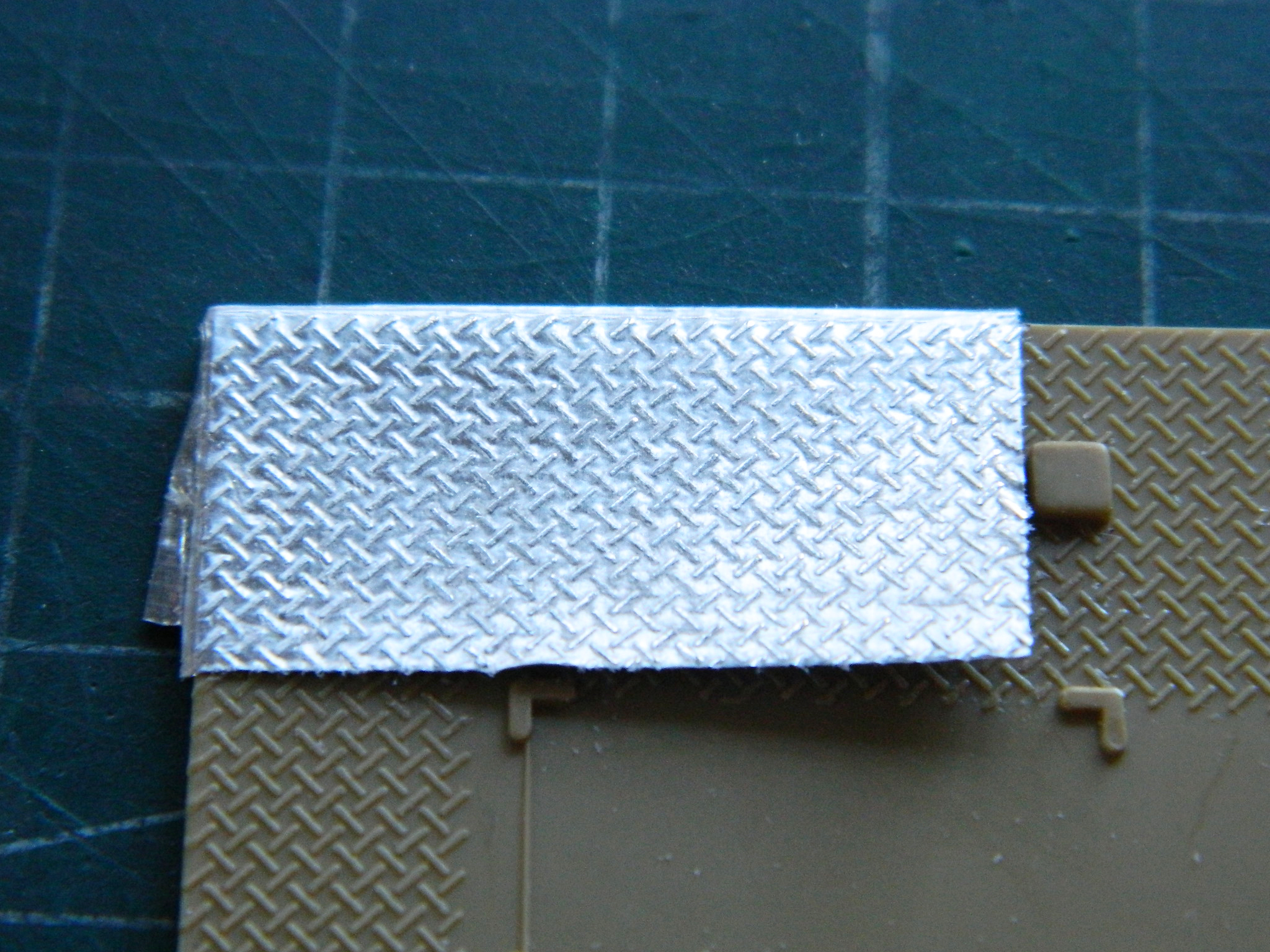
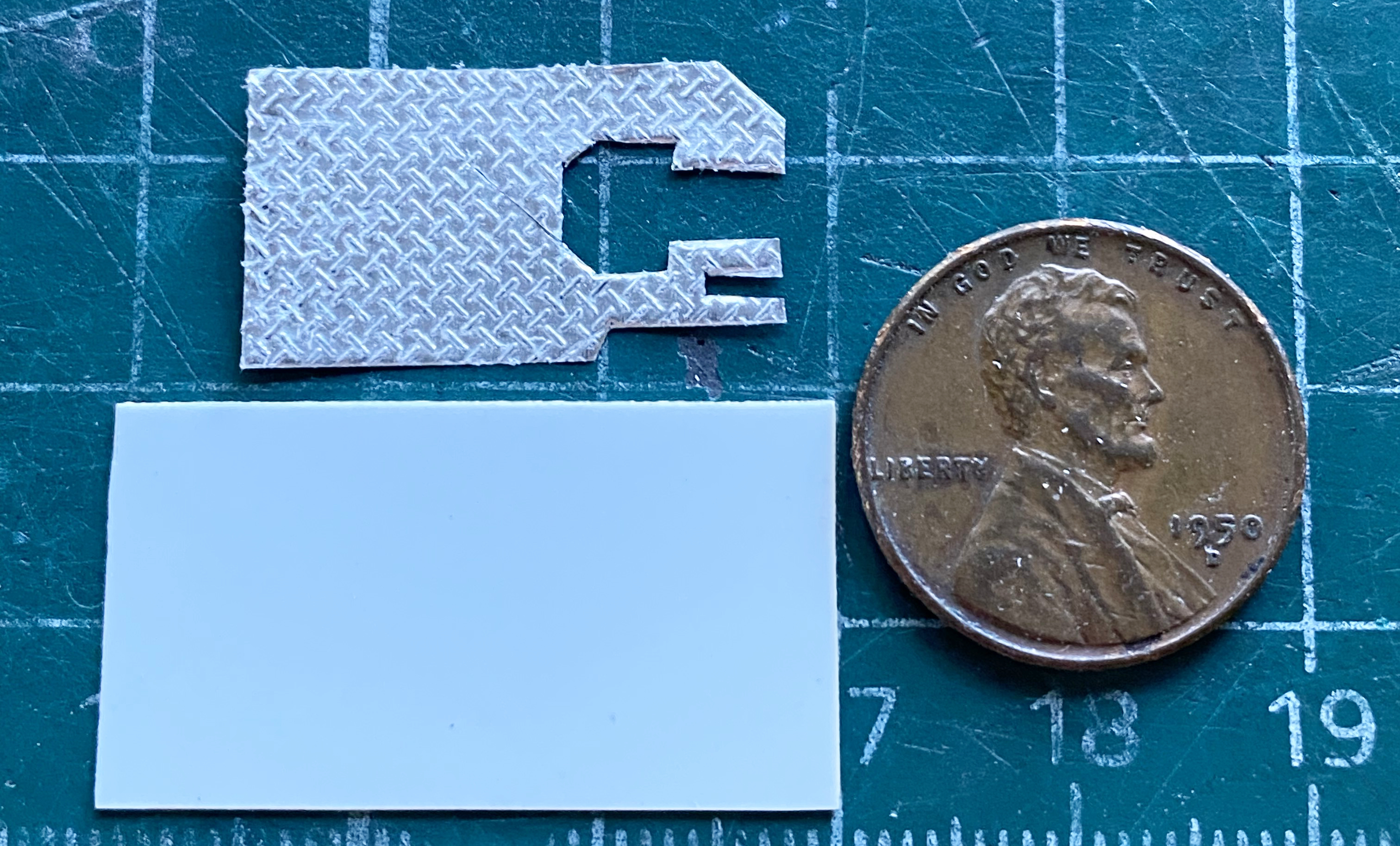
Then the PE part was traced over the foil and trimmed to shape:
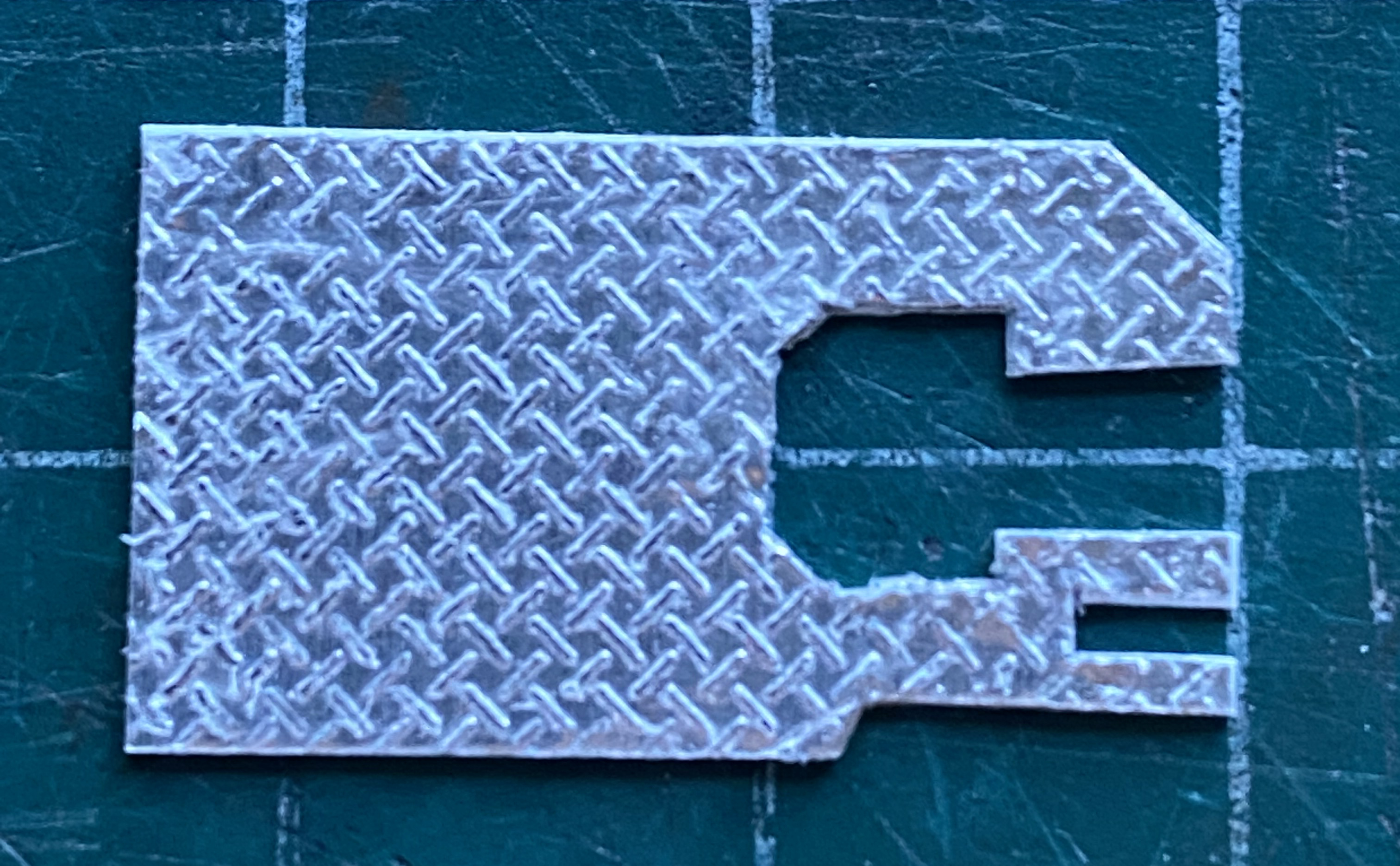
Even though the aluminum is heavier than the standard foil used in kitchens, there isn’t anything very structural about it which required I add 0.010″ (.254mm) styrene as a backing plate:
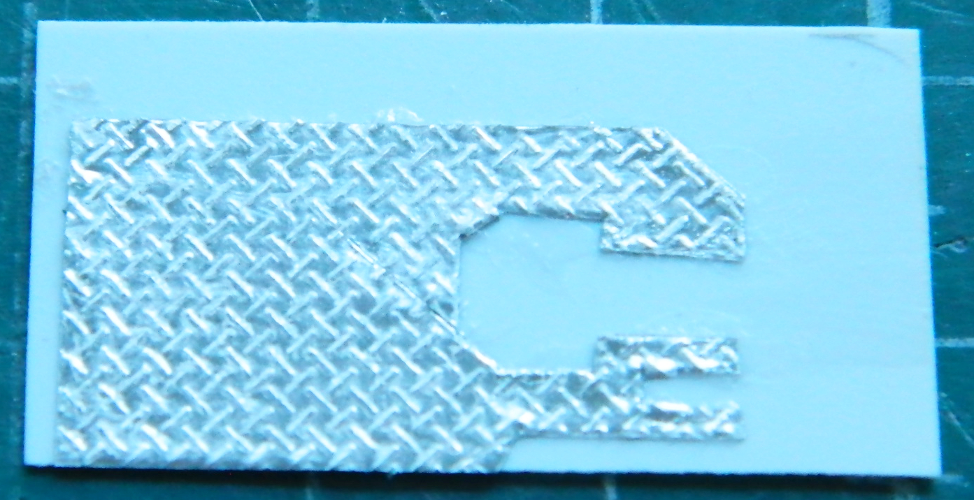
Which were given the final trim using the razor/hammer trick:
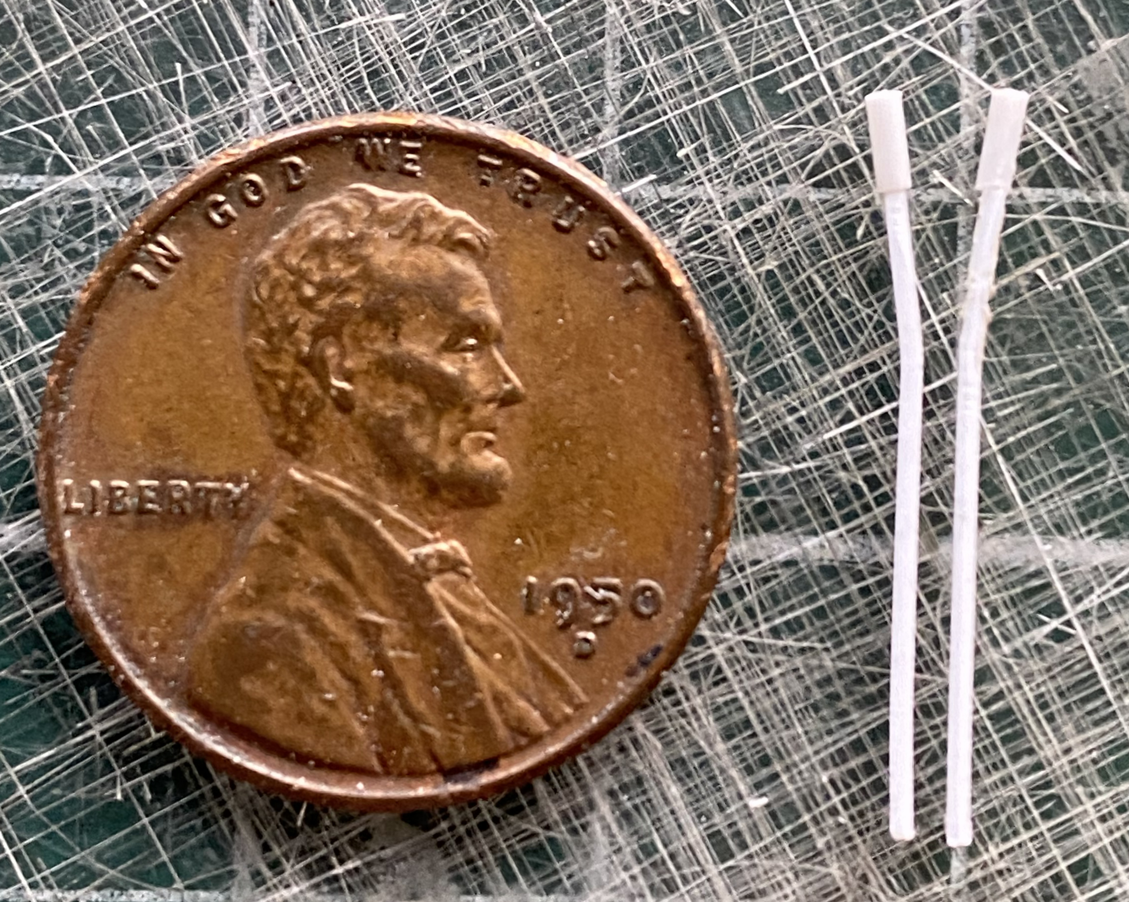
The braking/steering levers were resin. I have warm hands. Why do I mention that? Because if you want to change the shape of a resin casting, like maybe it was misshapen or warped, warmth returns enough plasticity to the parts to allow them to be reshaped. Yeah. The levers were so small that just the delicate task of removing them from the pouring block warmed them enough so that I felt as if I was trying to carve a strand of cooked spaghetti. I replaced them by using 0.020″ (.508mm) styrene with 0.035″ (.890mm) grips. Since the pivot shaft had been cast in halves and attached to the levers, that also had to be fabricated:

As you can surmise from seeing the driver’s floor sitting on top of a penny, these are small parts. Fairly small parts. This is the foot-throttle:
Warm hands also turned that rubbery. It was adjusted to shape. Often. Even frequently sometimes.
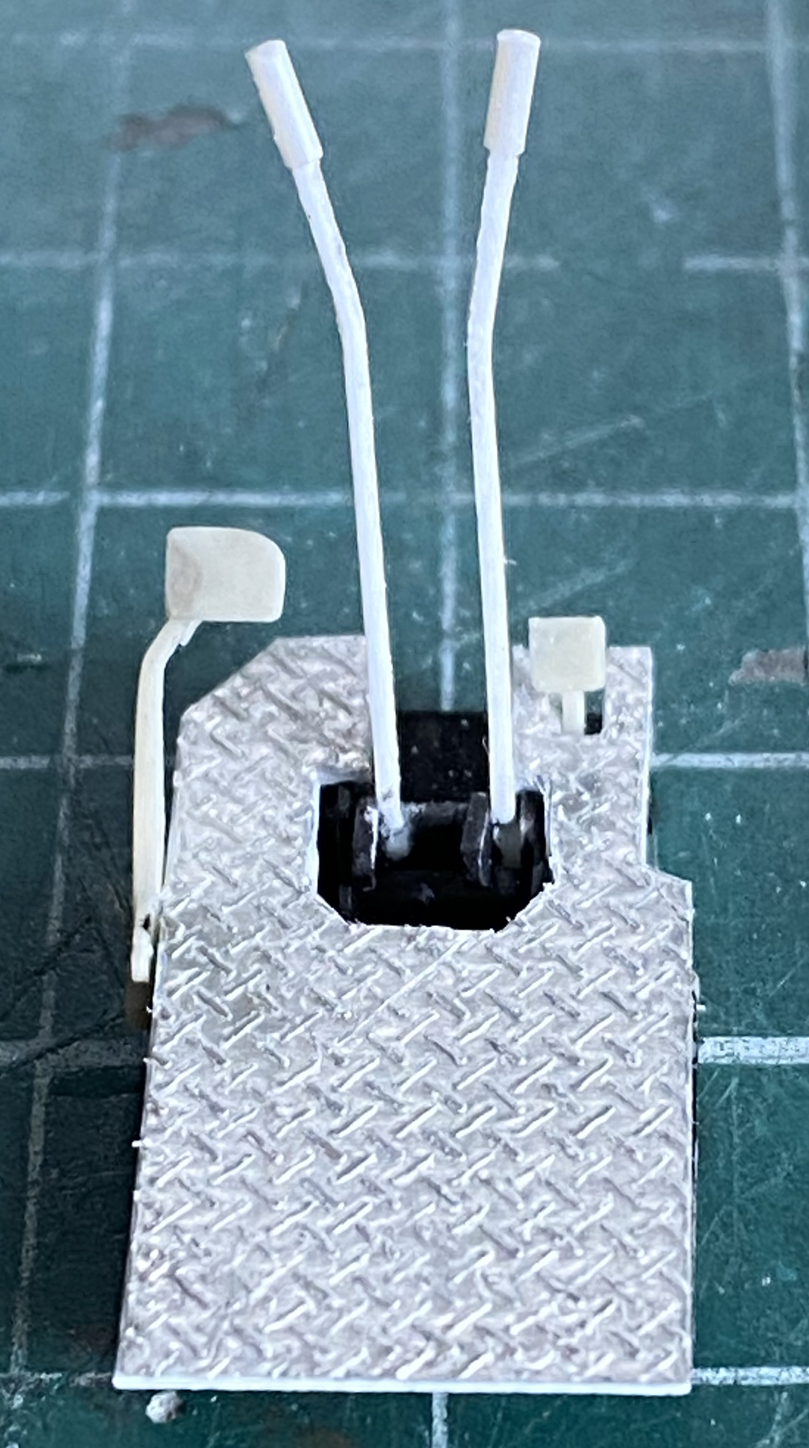
The grips were added and the proper angles of the levers adjusted:
All the other parts were removed from their pouring blocks, rubberiness dealt with, and after painting the sub-floor flat black, it was assembled:

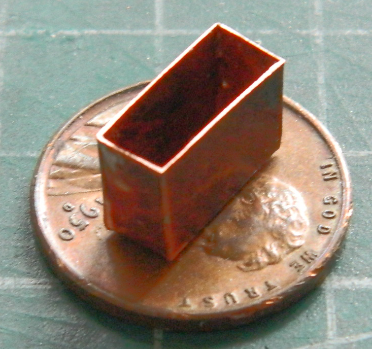
There is a partitioned box that sits on top of the transmission that’s intended to stow spare periscopes in. I replaced the PE part with .005″ (.127mm) copper shim stock and even managed to solder all four edges where they meet!:
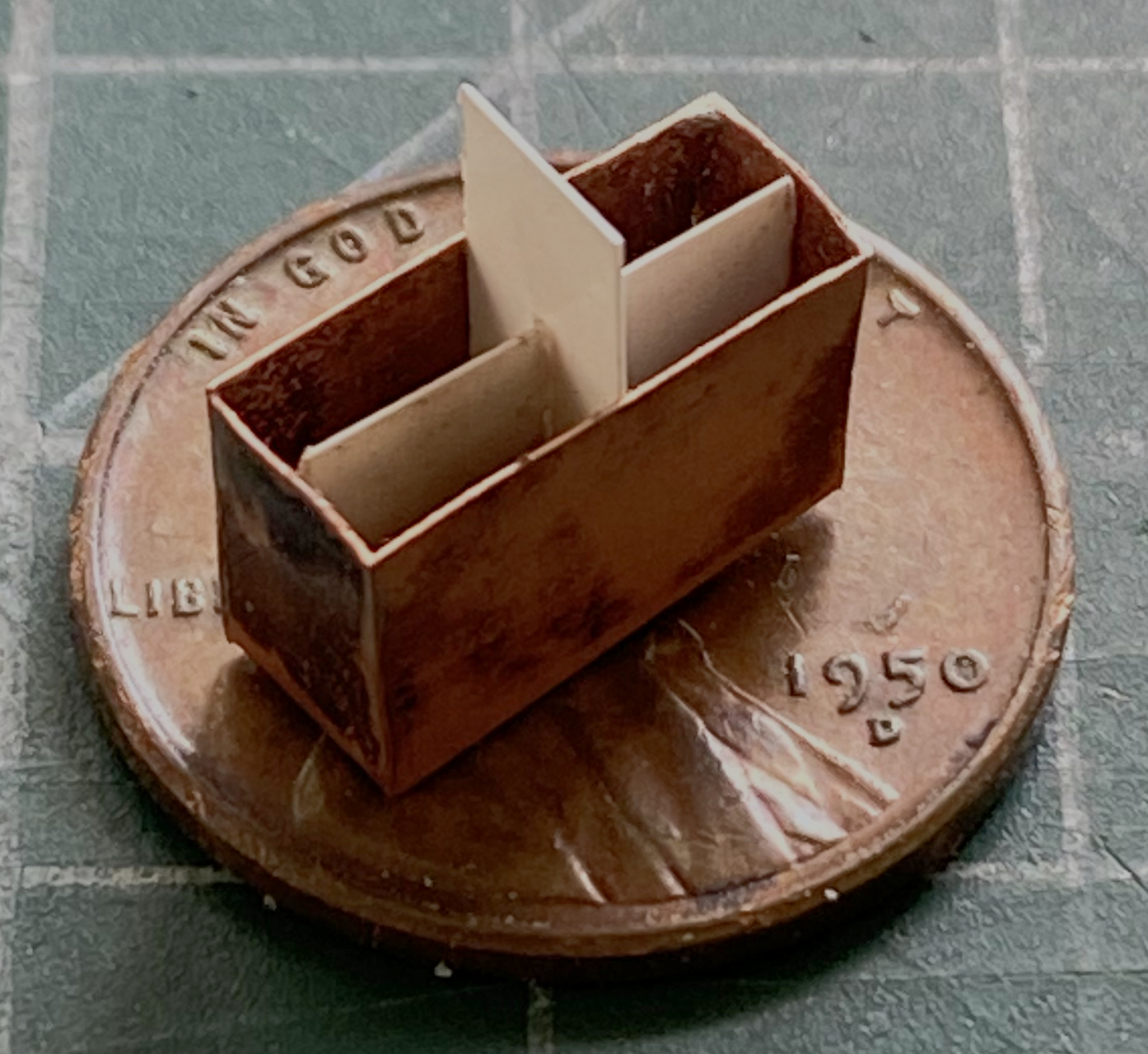
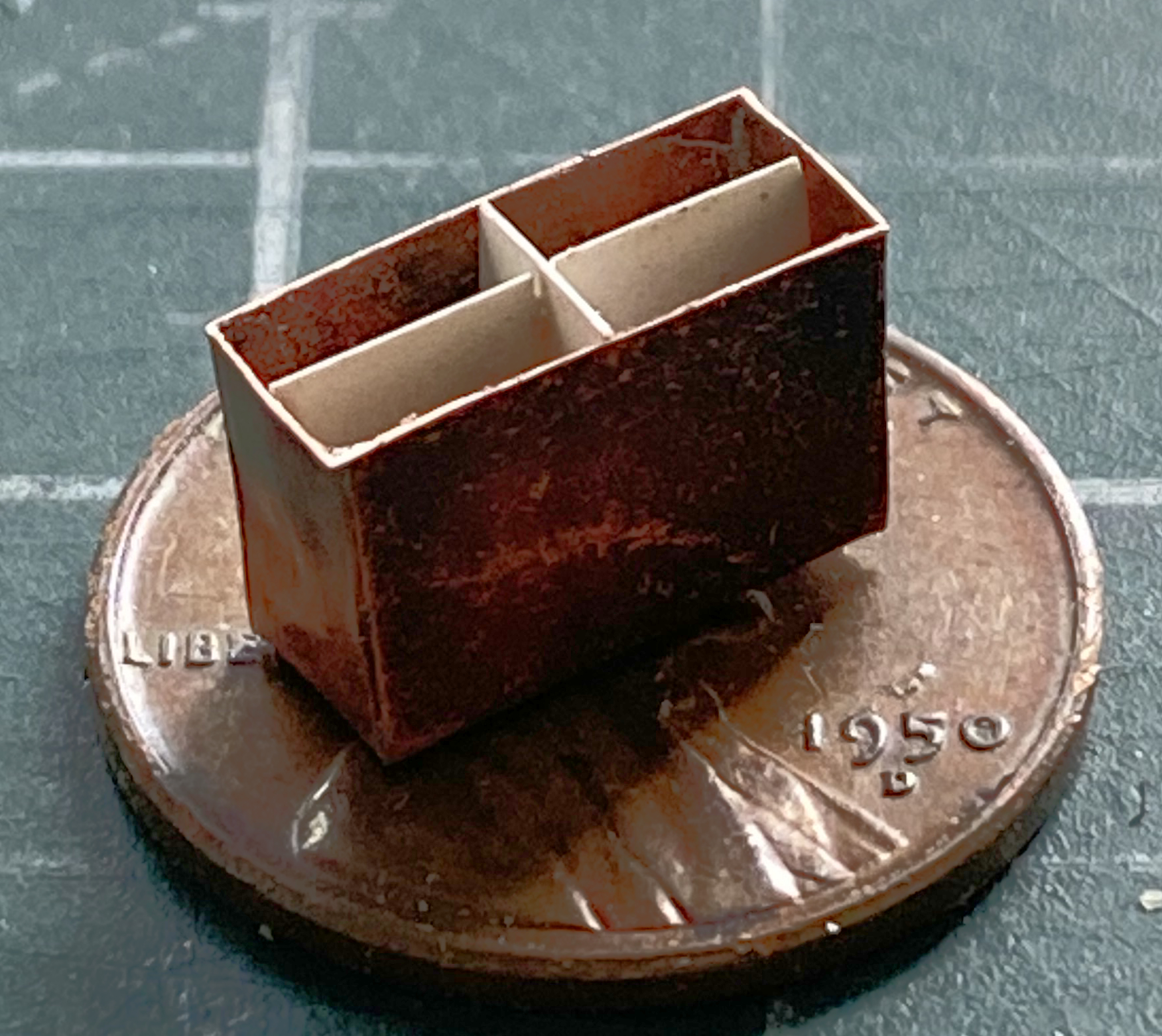
I used a fine file to true the edges around the opening so that they are all even and then added .005″ (.127mm) styrene to the inside to complete the partition (it took me longer to add just the styrene than it took to outline, cut, file, solder, and file again the copper box):
Assembling the bits for the lower hull continues next month.
