Once I’d made the basic (very basic) additions to the seats, I taped everything together and checked how things fit…and they don’t. Without the additional details, the seats barely fit, and with the additions they don’t fit at all. ::sound of screeching brakes on soundtrack:: I needed more room.
But I don’t have more room! I mean, this cabin has to fit inside the outer hull. So I wandered around for a while, mumbling, bumping into things and scaring the cat:

Then I realized that the only place the cabin needed to fit was the periphery where it mates to the outer hull. So if I sectioned the sides of the cabin and moved them out, that should give me the room I needed. No, the actual Gemini capsules don’t have their sides moved out. But unless I want this project to stop here (which I do not), then something has to be done. What matters is that things look right and seats that stick out of the hatches certainly don’t meet that criteria!
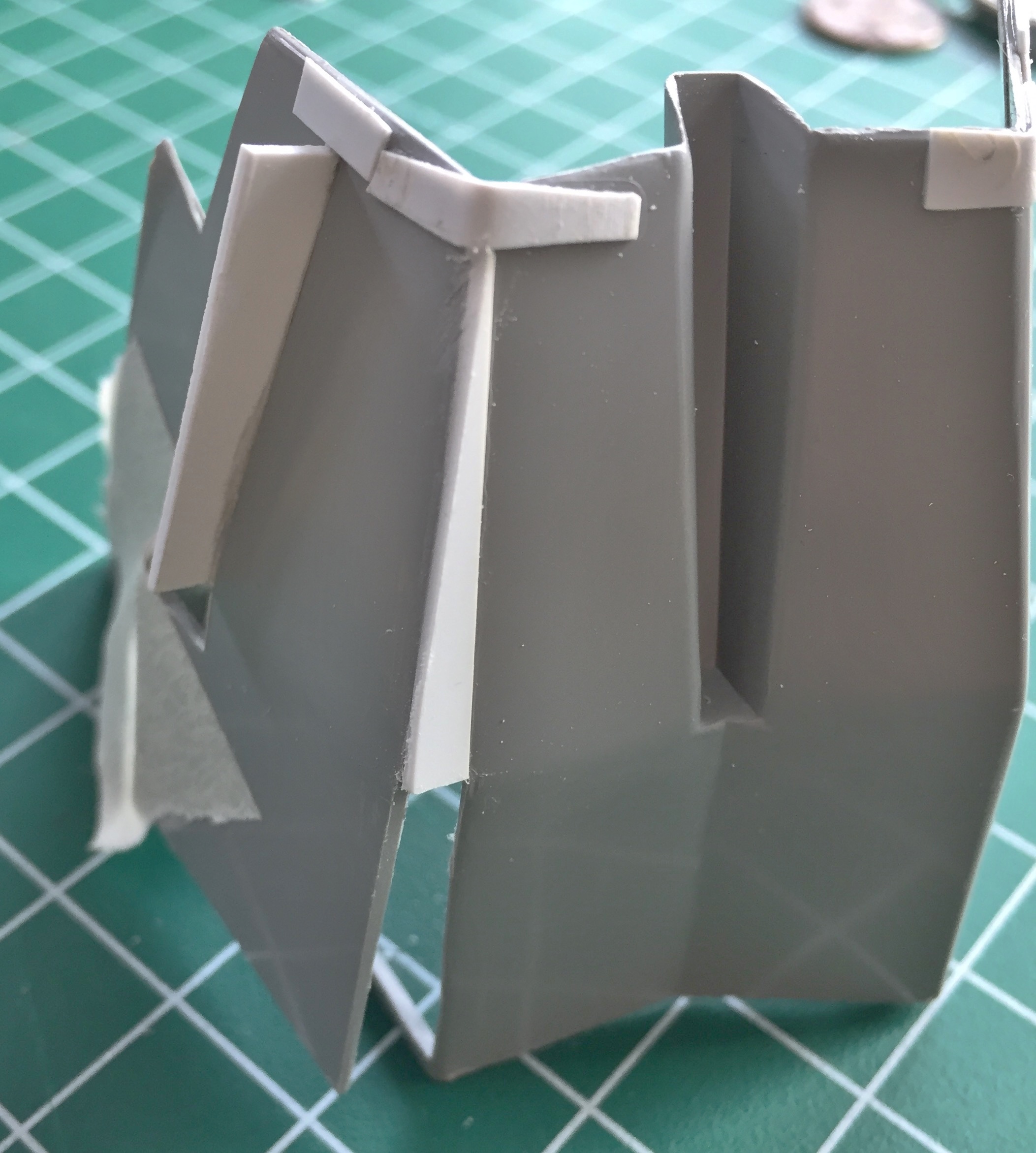
Step one was marking the area that needed to be moved and laying electrical tape in place to act as a guide for my scribing tool:

Once I’d scribed and sawed through the plastic, I cleaned up the edges with a file. Since I didn’t cut through on all sides, I had a section in front that would serve as a hinge. A thin hinge. A hinge thin enough to snap the plastic so those areas needed to reinforced. I fixed where it had snapped and reinforced the other side before beginning work there:

That allowed me to bend the side out without anything snapping (again):
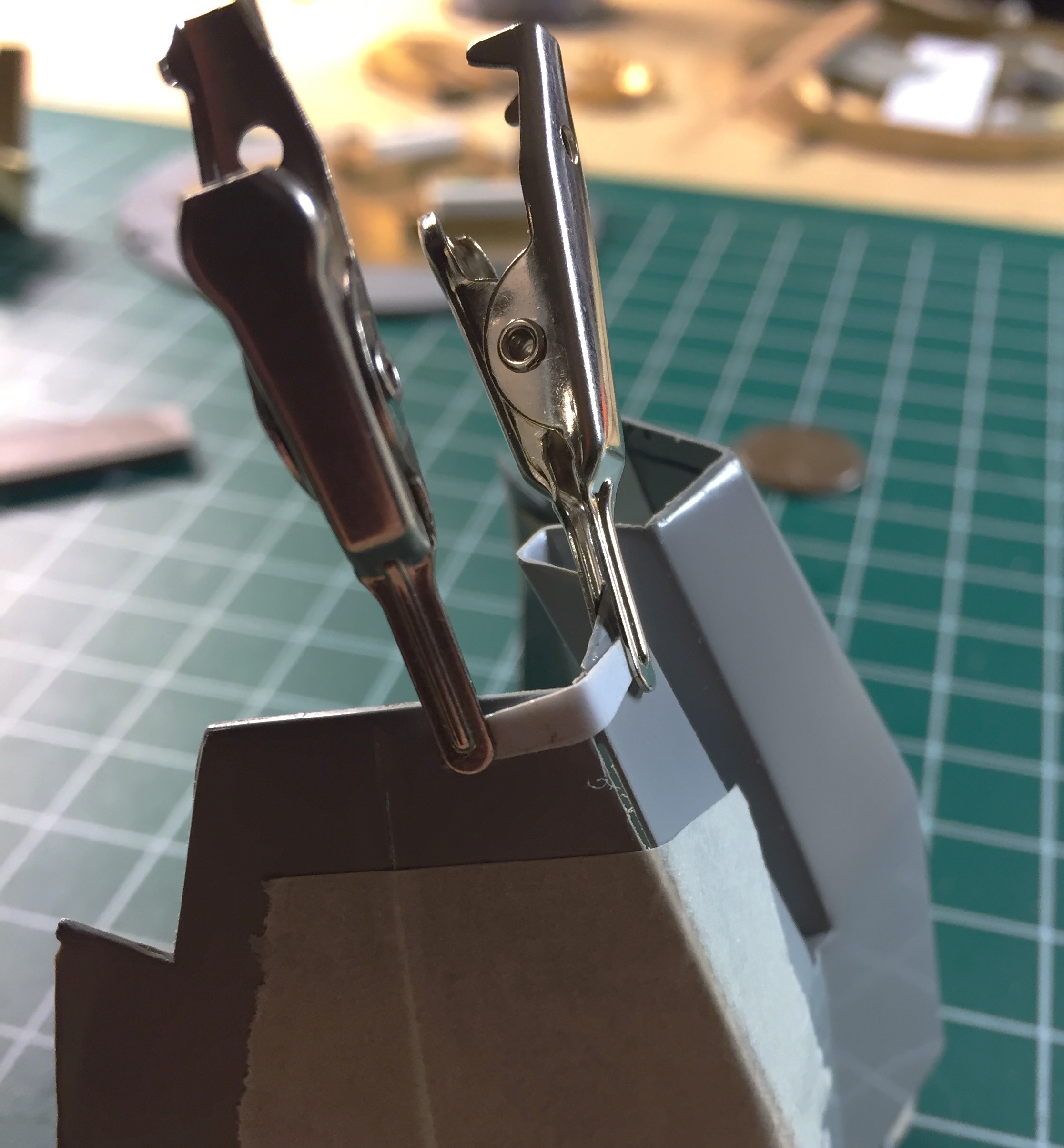
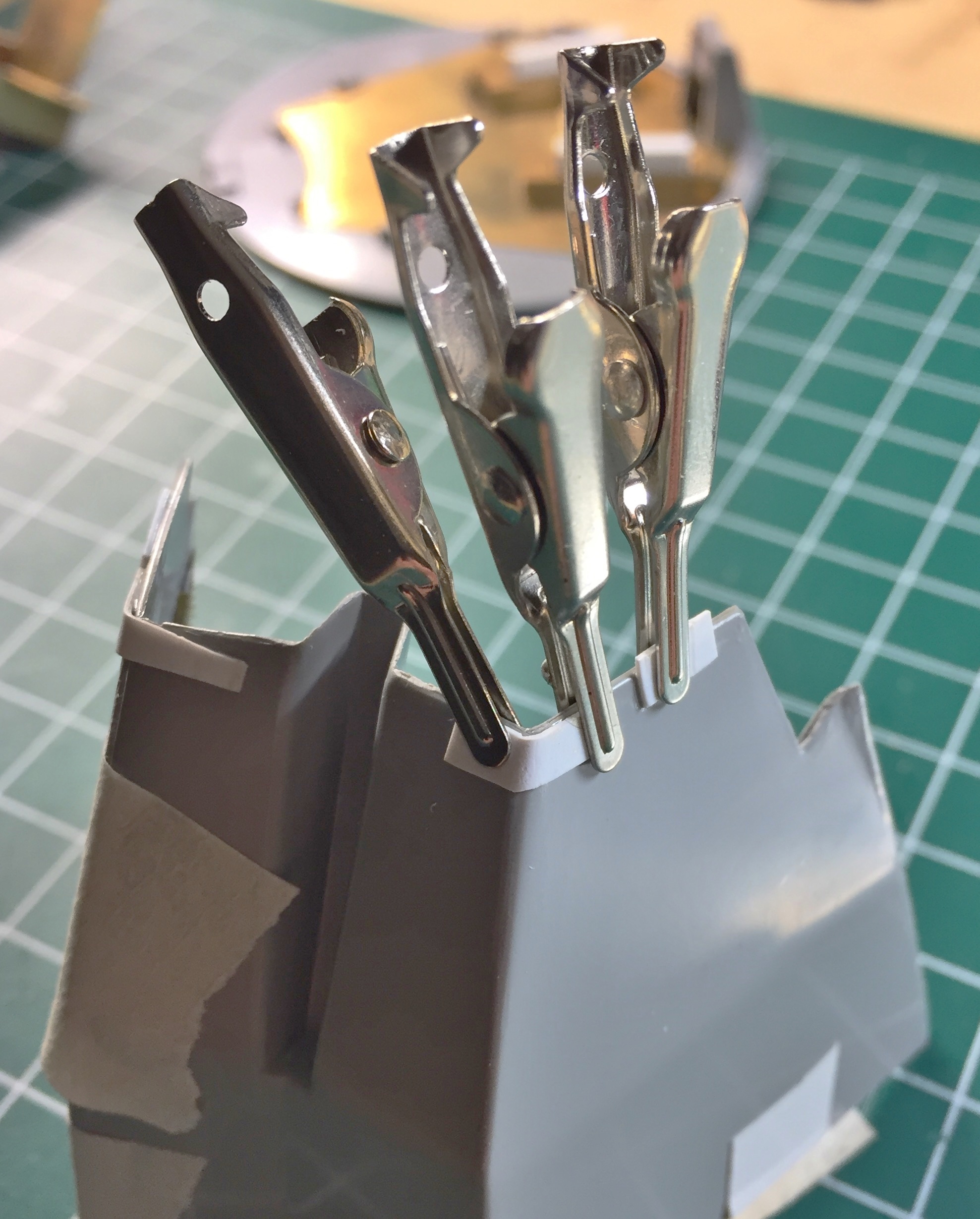
For strength, I boxed the open sides using .040″ (1.016mm) styrene:

Once I’d finished boxing the side, I trimmed the excess:
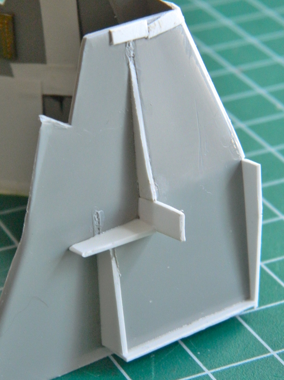
And that left me with this:
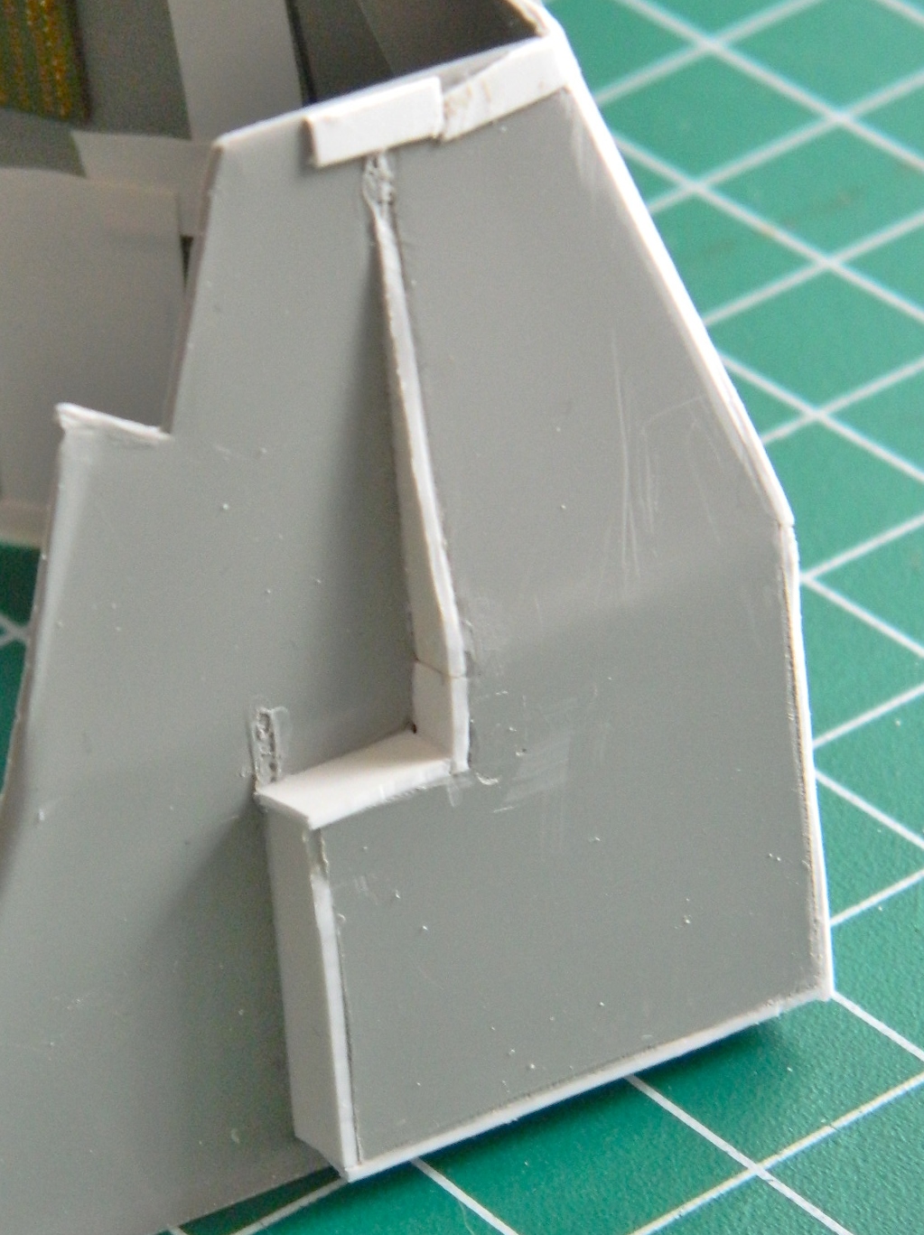
The seams got a coat of putty, sanded smooth, and then the seats were dry-fit:

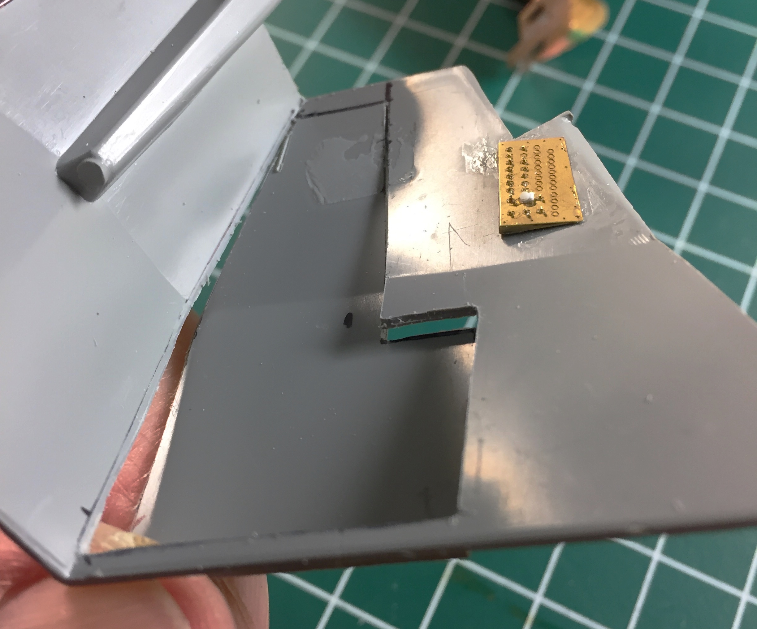
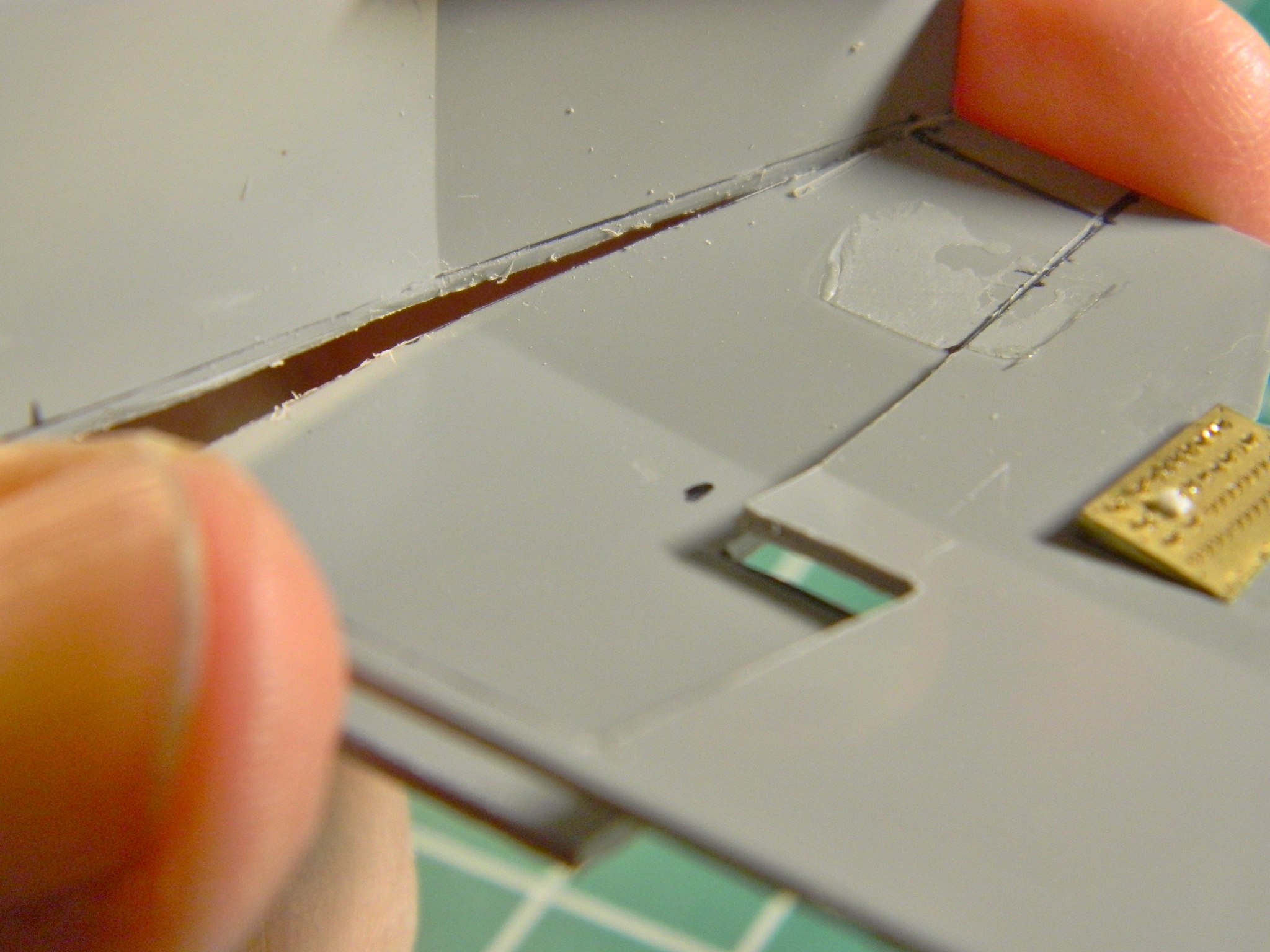
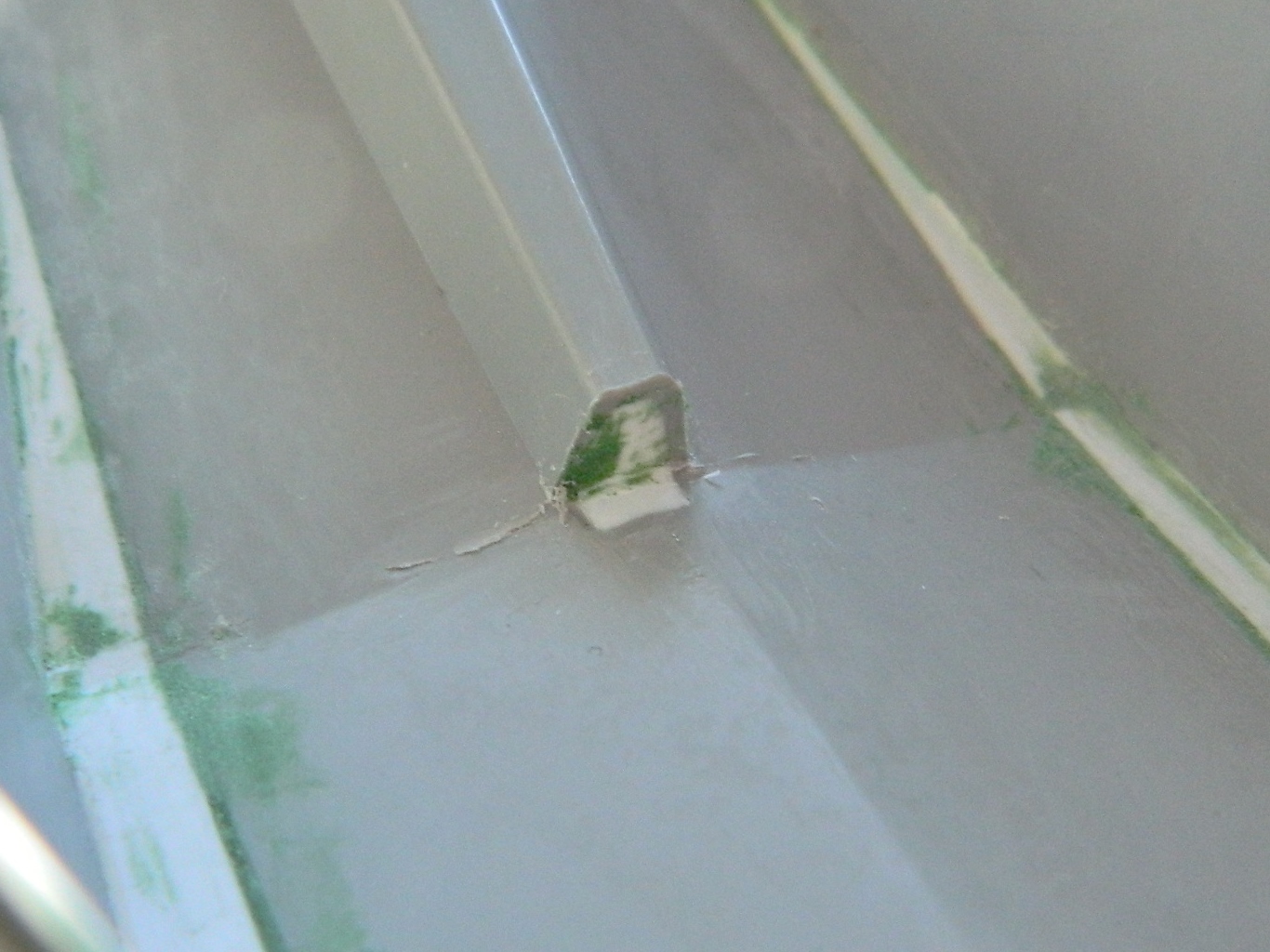
Things fit, mostly, except for the center (and a little bit of trimming of the copper shim stock I added). To get the seats to sit as far down as they need to, I have to trim that. Since trimming away the end of that raised area cut all the way through, I had to add a piece of .080″ (2.032mm) scrap to fill the holes, trimmed it to fit, added a bit of putty, and sanded the area smooth:

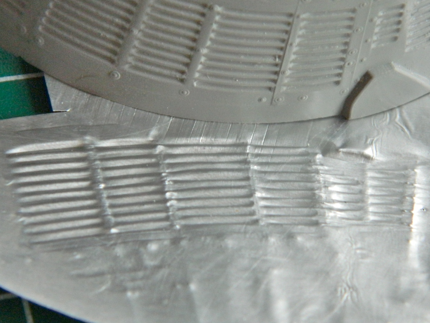
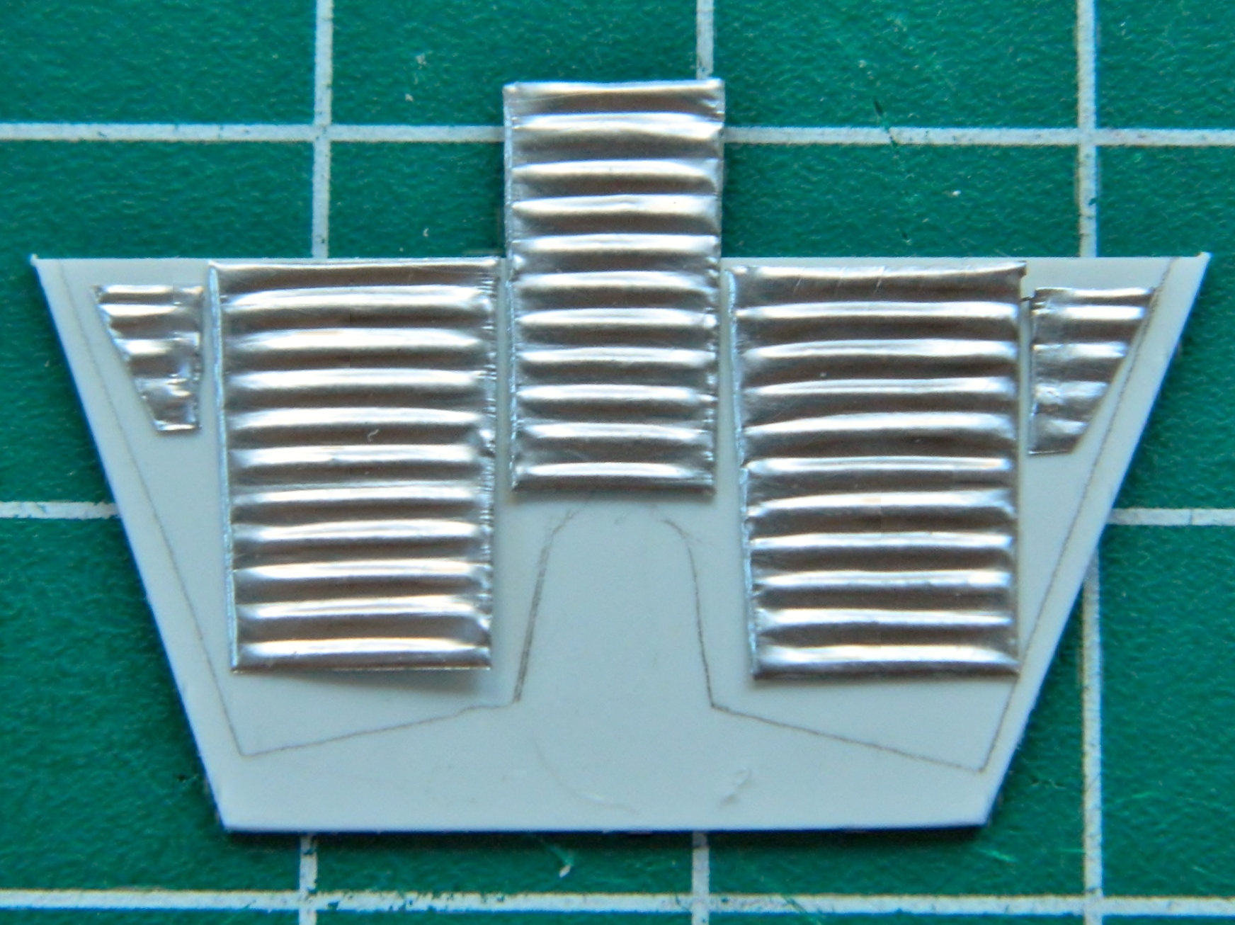
During dry-fitting I noticed that the open front of the cabin was visible. While I was modifying the cabin walls and floor, I mocked up the part I will fix that with. I’ve also noticed that the walls of the cabin are also corrugated. I took some heavy aluminum foil and rubbed the exterior corrugations to give me thin corrugated panels that will get glued and puttied onto the front wall later in the build:

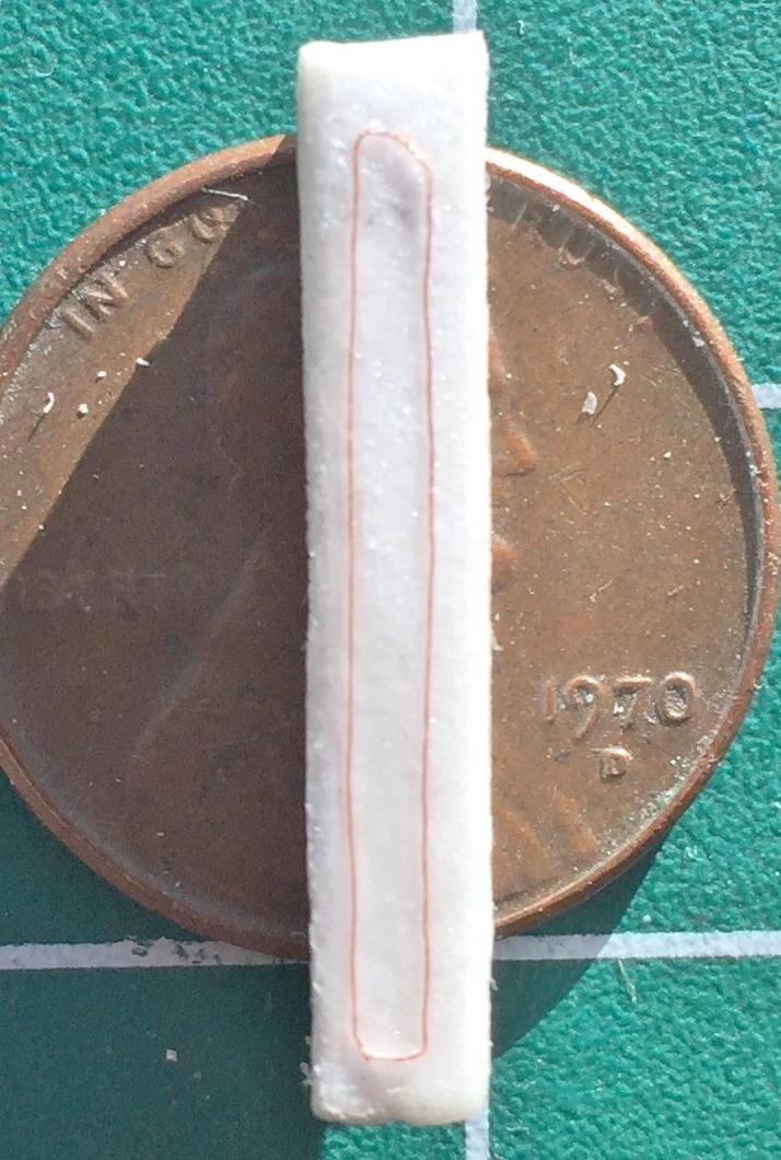
Getting back to the seats (that will now fit into the cabin), I had to add fabric texture to some of the parts. That long, white, piece of plastic is actually a zippered pouch and it needed a fabric texture (and there are other pouches behind the seat that need adding and fabric texture). I’d considered tissue paper and diluted white glue but it didn’t offer me quite the texture I was after. I ended up using a flushable wipe (which, I’ve come to find out, aren’t at all flushable…I mean, you can flush them, but you can also flush marbles, too…doesn’t mean they’ll dissolve) because of its woven texture (let them dry out first):
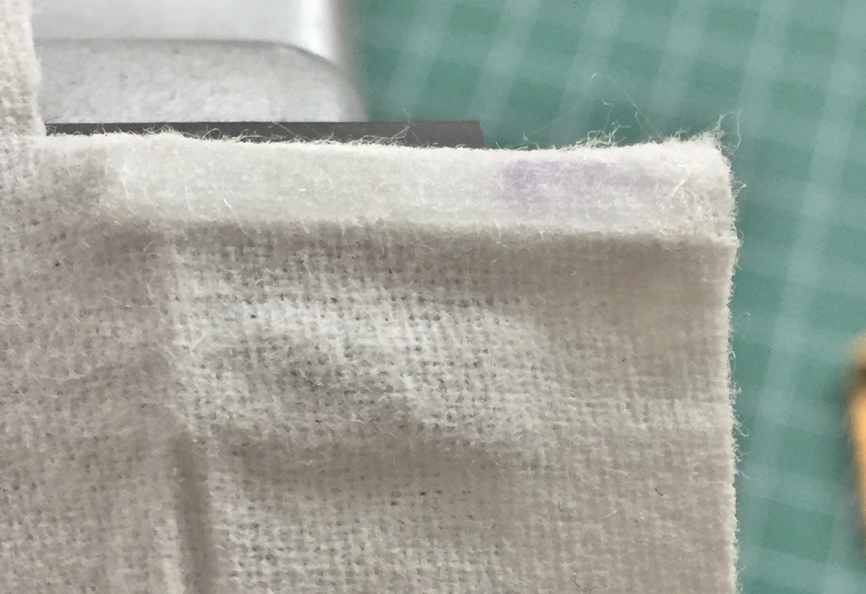
I draped the wipe over the plastic and then dripped superglue through the weave onto the plastic. Once the glue set, I added a bead using 40 gauge wire. The front of this compartment zips open and there’s a welt that runs around the zippered opening. Later after it’s painted I’ll draw the zipper in using a sharp pencil:

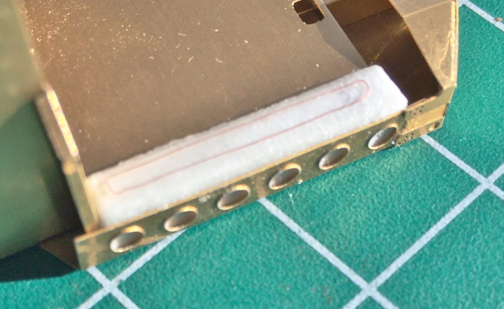
Some additional trimming of the fabric is needed, but even as it is, it looks much better than bare plastic:

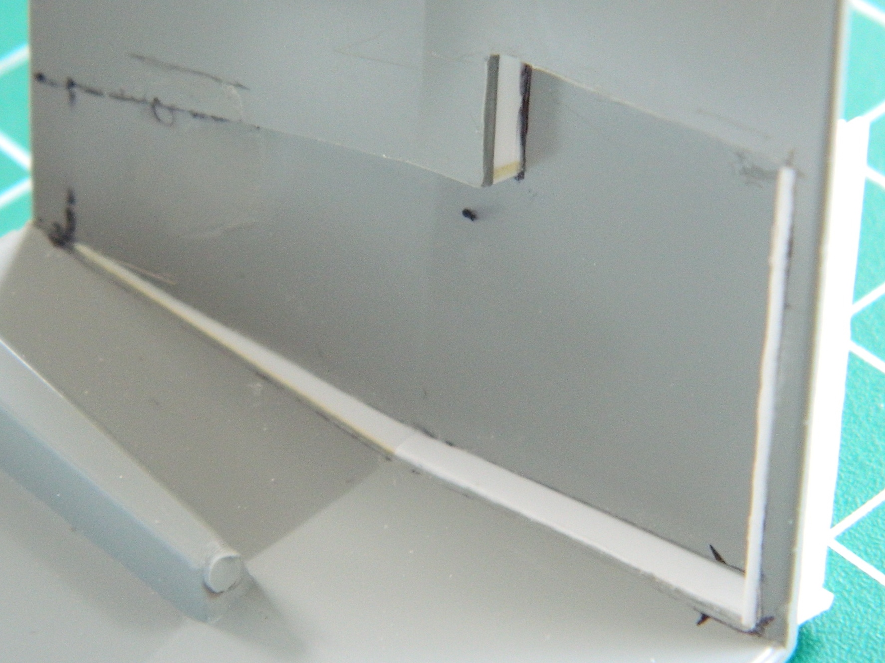
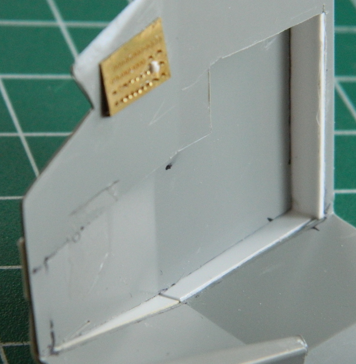
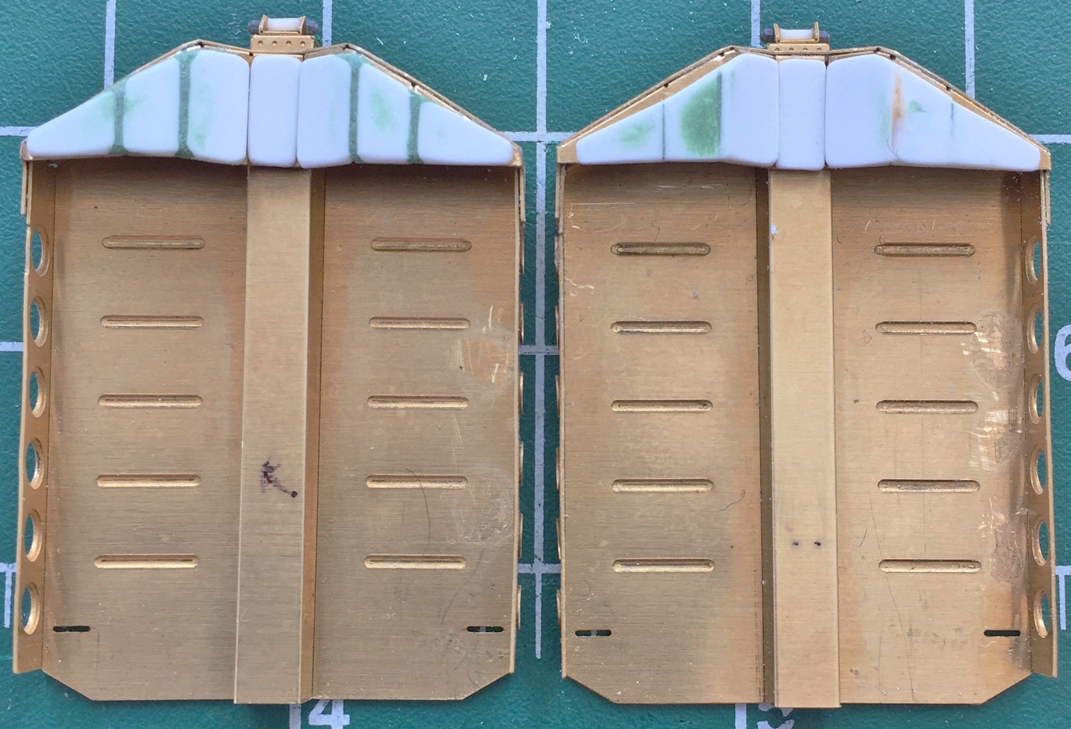
Needing a short change-of-pace, I checked to see how difficult it was going to be to open areas that were molded solid. The rectangles around the periphery of the rear cabin wall are actually openings that the catches of the hatches go into to close the hatches securely. Ideally those are hollows. Since they weren’t molded that way, I wanted to see if I could cut the hollows into the kit piece or if I was going to have to cut away the area and build something less inaccurate:
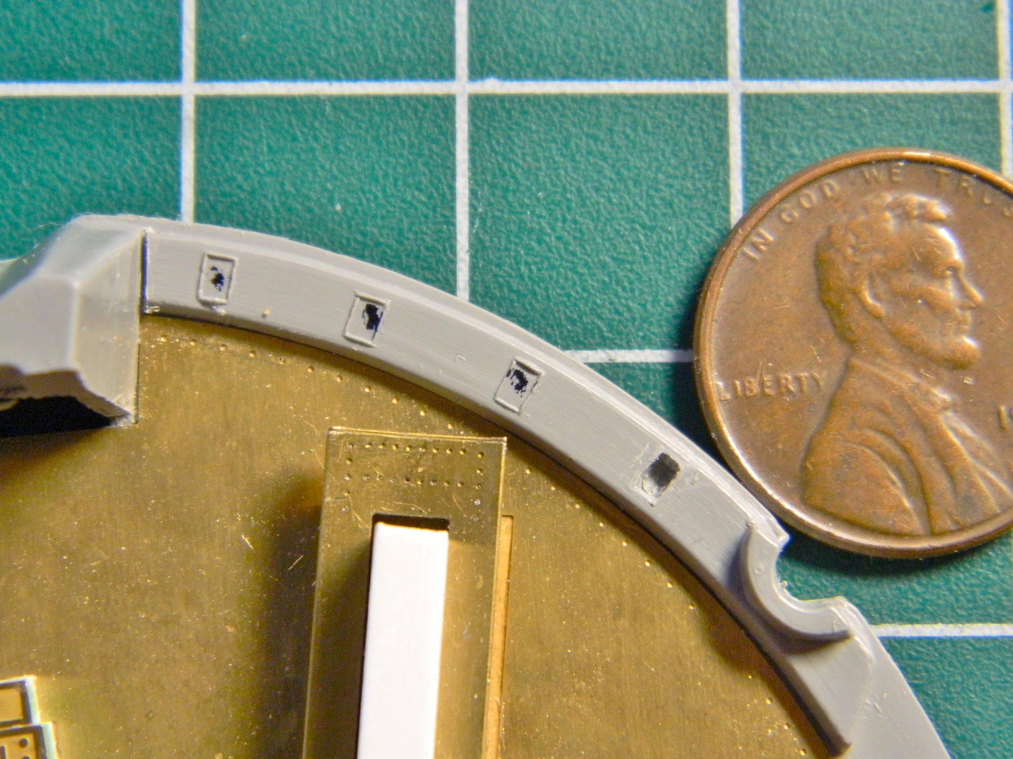
I can hollow out the individual sections. It’s a bit tedious but I can do it without (more) reconstructive construction.
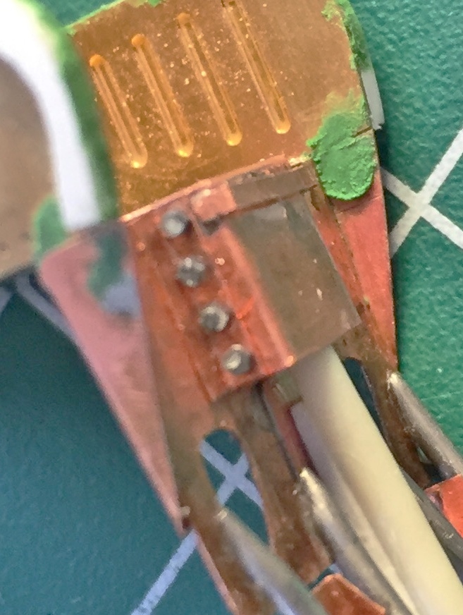
Back to work on the seats, I added the support for other details (the function of which I cannot fathom so there’s no label for that strip soldered between the two loops) for the foot stirrups (which were intended to keep the feet and legs from flailing around and getting injured should the crew need to eject) using solder:
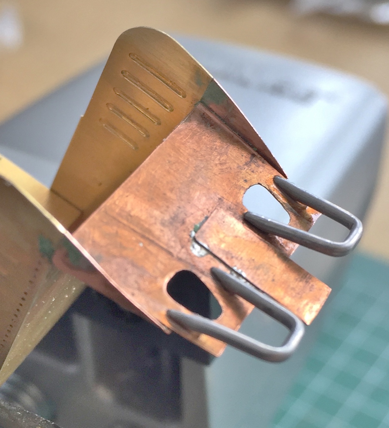
I didn’t realize at the time what a major ass-pain these things would turn out to be. They snap off with the slightest provocation and attaching them is another major ass-pain…and I got to reattach them frequently.
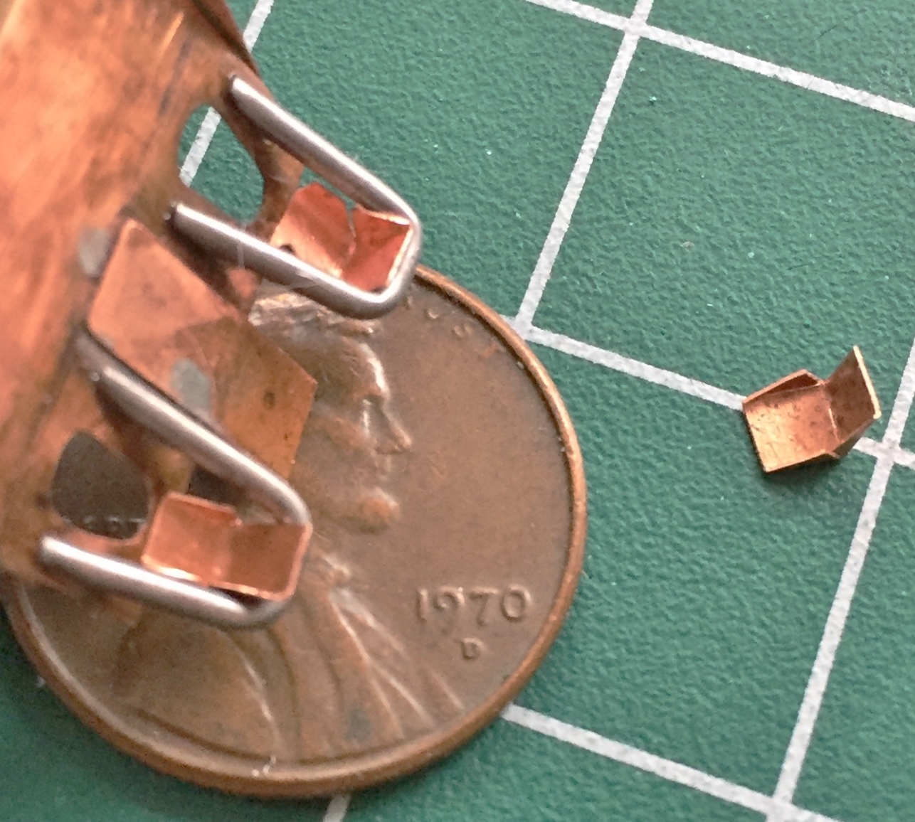
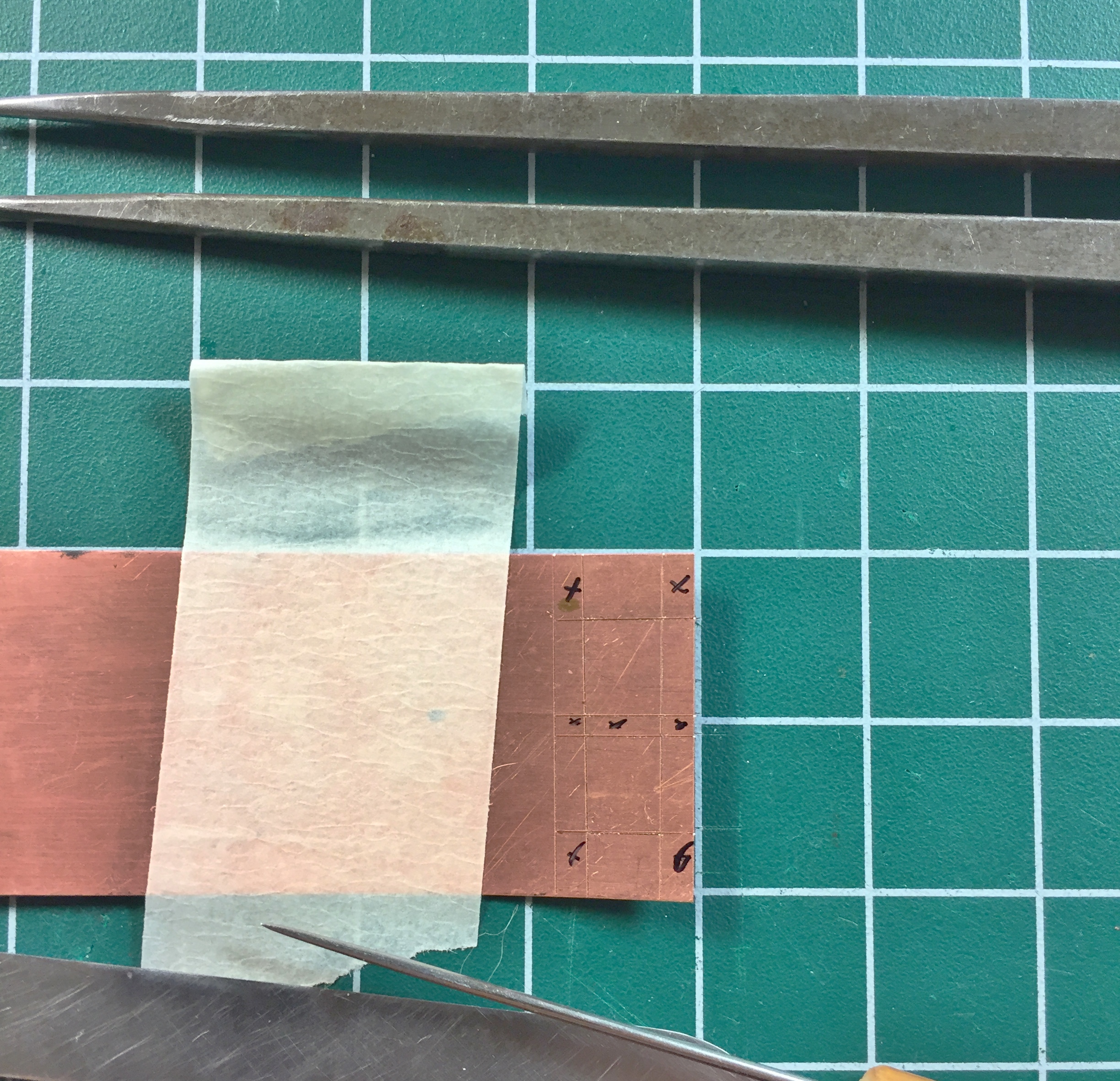
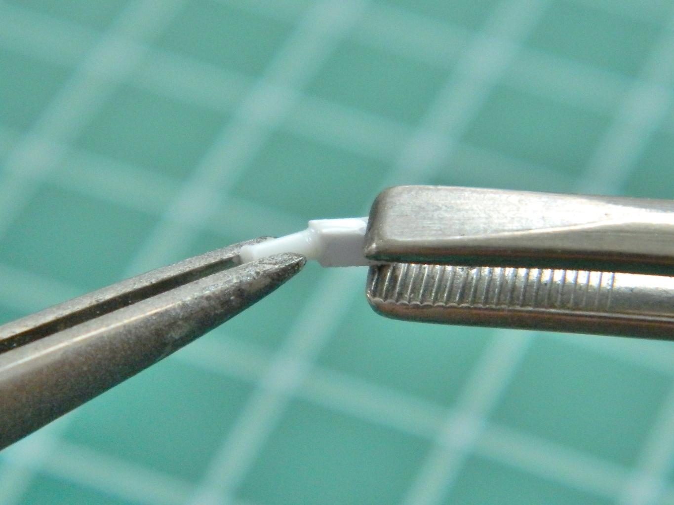
There are foot rests for the stirrups (wouldn’t be much of a “stirrup” without them, I guess). My first thought was to make them out of .010″ (.254mm) styrene. My second thought was to not do any work until sober. My third thought was to use the .005″ (.127mm) copper shim stock instead. Scale thickness is more correct and for all of the annoyances of working small copper sheet like this, they’re a lot less annoying than trying to do the same thing with styrene. First step was to scribe the lines I wanted and then cut them out. I used scissors for the longer…all terms being relative…sides and a SHARP chisel bladed knife for the notched cutouts on the sides:

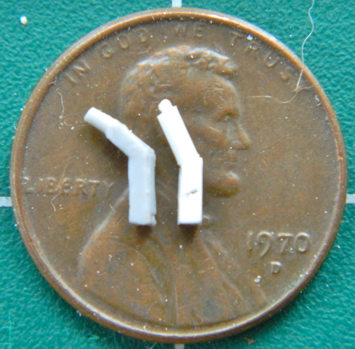
As it turned out, I got the pattern incorrect. I diddled around until I got the pattern and sizes (plural because I wasn’t exactly standardized about the solder stirrup supports) correct and then superglued them into position:
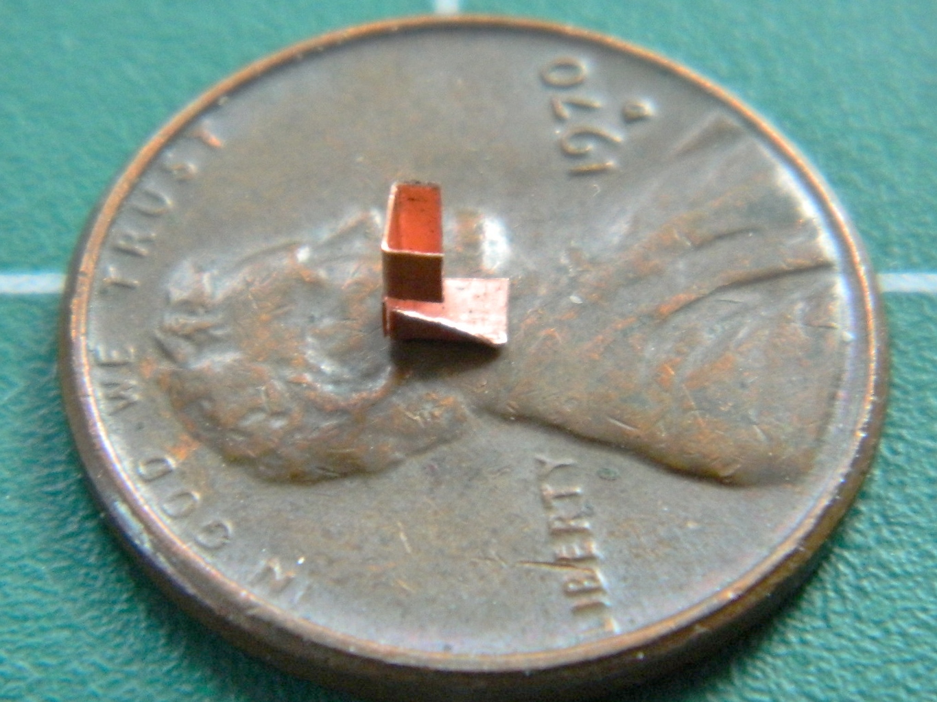

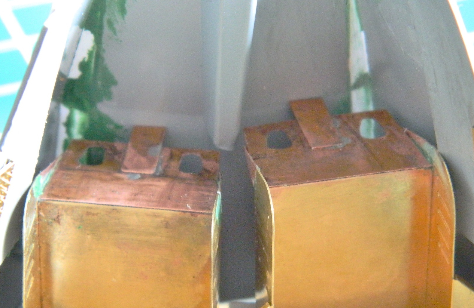
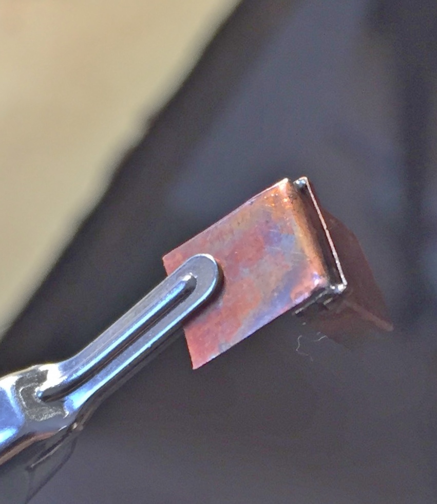
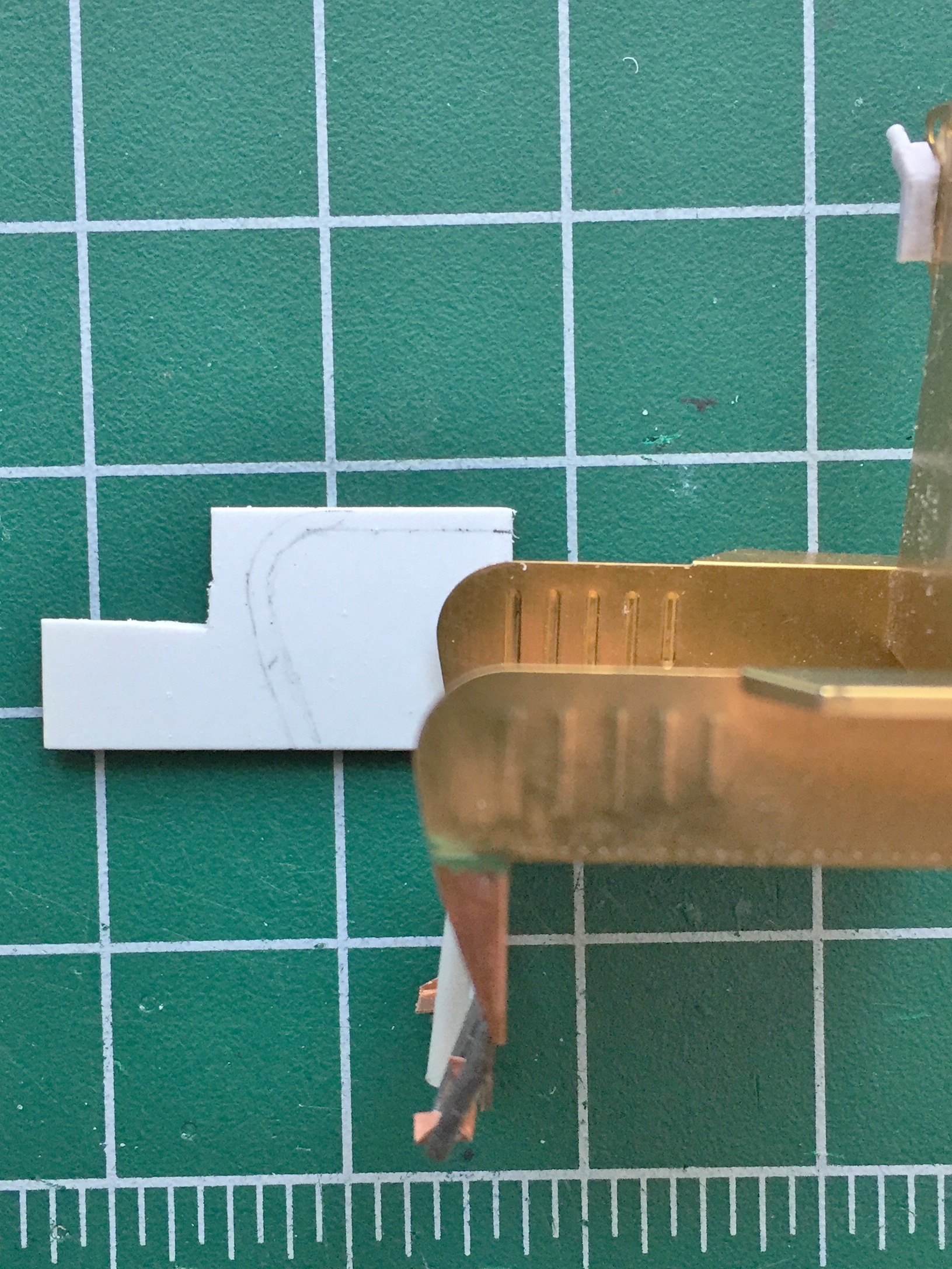
There’s a prominent box on the front face of the seat that the ejection seat trigger is mounted to. Again, I used the .005″ (.127mm) shim stock and again I got the pattern slightly incorrect:
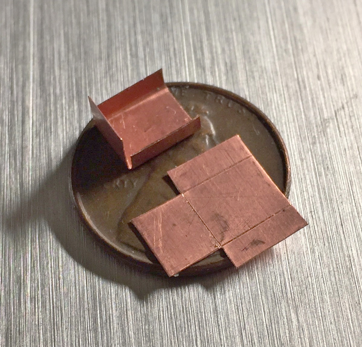
The pattern is incorrect because I forgot to allow for the dimensions of the sides; that has to be added to the flap at the top (as indicated by the penciled outline on the seat):

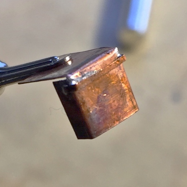
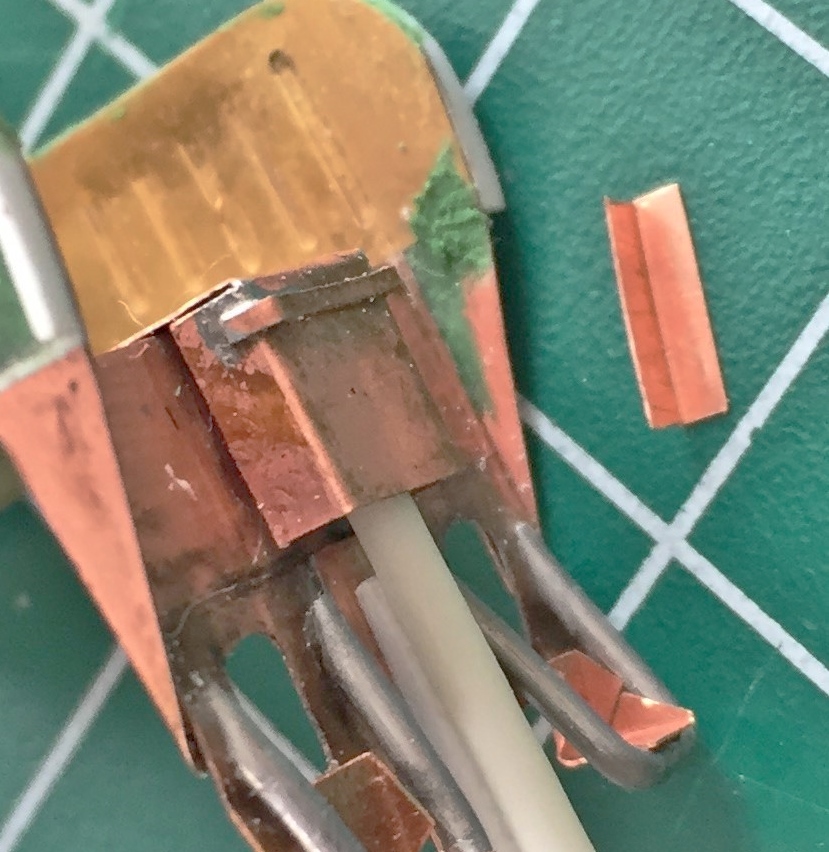
With the boxes properly dimensioned and folded, I needed to add a support bracket for the ejection trigger handle. I impressed myself by soldering these SMALL brackets into place:
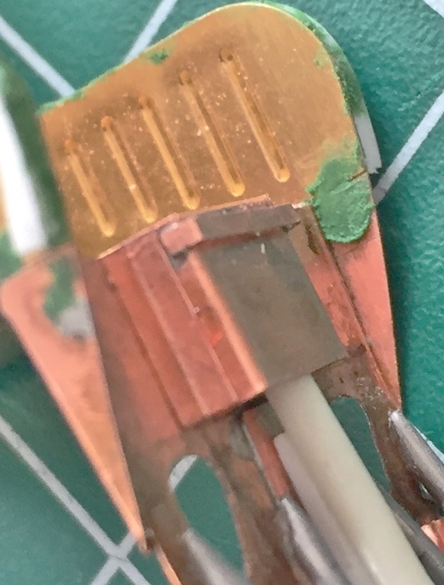
Then I added the mysterious details between the stirrups:
The headrest area of the seat frames have padding. This is where the references get…interesting. For a great many of the details shown in a photo as looking like this, there’s another photo that shows it looking like that. I imagine that’s because of the different mission parameters and goals, but it’s…interesting…when trying to find out what something looked like. So I picked one design for the head rest padding and went with it. Then, while looking for something else, I ran across another reference photo that showed the headrest padding of a different design that matched the seat padding I decided on. Sure do wish I’d found that before I superglued the pads in place… That meant the gaps between the individual pads got filled with putty:
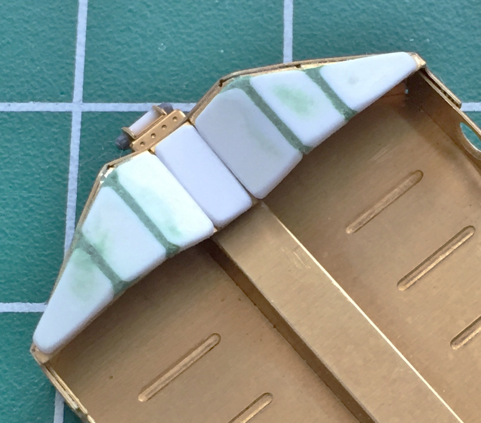
The second headrest padding went easier:
The sides of the seats are also not as thin as the PE parts would have them be. I added thickness by using .040″ (1.016mm) scrap:

Yeah…looks much better:

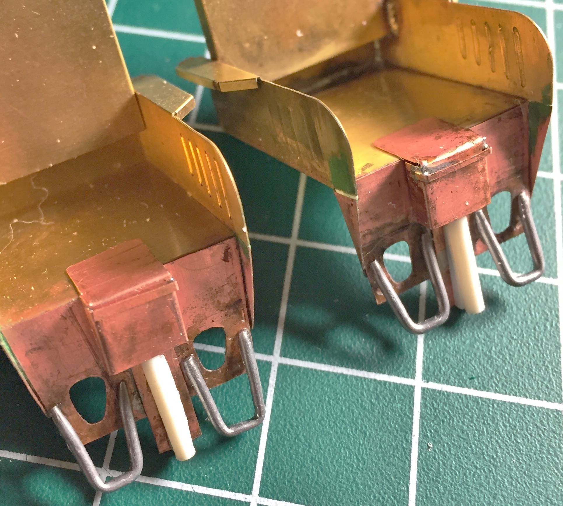
Another thing I noticed about that box at the front of the seat is that there’s a 90-degree mounting bracket that I had to add. And this is good because there’s a gap between the body of the box and the front of the seat that these brackets hide nicely:
The box is mounted with bolts and I used Grandt Line bolts to replicate that (sorry about the blur; the camera DID NOT want to focus where I wanted it to focus) (stupid camera):
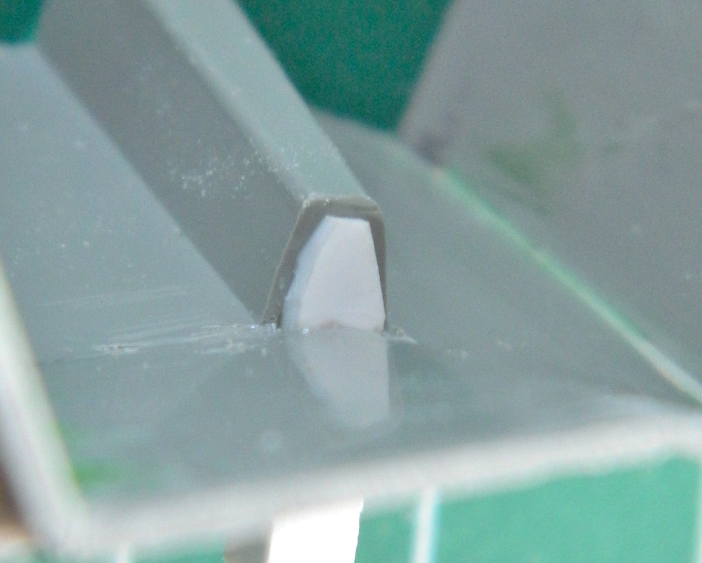
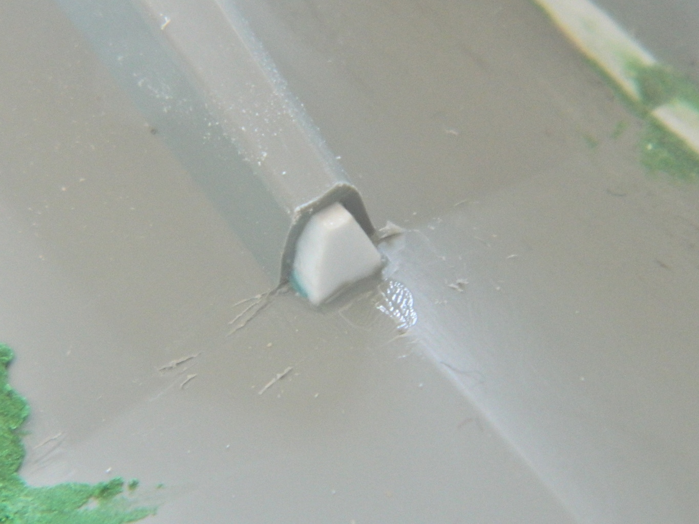
There’s another (mystery) detail on the side of the seat that came supplied with the AM set. Problem is, it’s inaccurate. The shape of the top is incorrect (should be round and not rectangular) and the angle is also off. Scrap styrene was used to fix that (those?):
Much better:

Having widened the seats, it finally occurred to me that maybe I might want to dry-fit the seats with the additional details that added width to an already cramped cabin:


Yeah, it’s snug, but it fits!
