Satisfied with the results of the salt-chipping experiment (and grateful for the break it provided), it was time to go back to work on the coolant manifolds. The putty was well set and I shaped them:
With the tapers done, I had room to add the rest of the coolant manifolds:
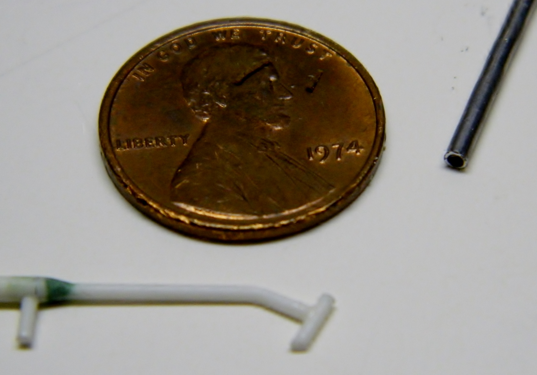
Because of the small size of the parts and the necessary bends them, using wire or plastic didn’t work. The wire is too stiff to bend and the plastic tends to crack and break when bent, so I went to solder again and I drilled out the end of the solder to fit over the manifold the way the rubber hose does on the actual tank (but more to avoid butt joints, really):

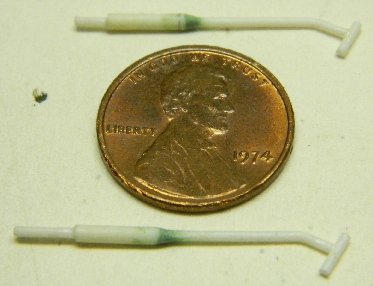
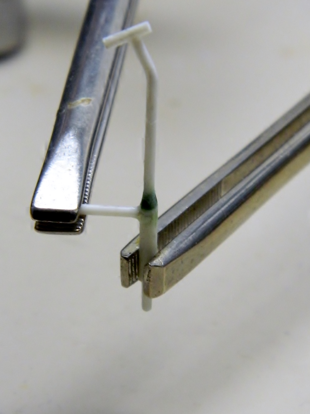
Also quite visible is the dipstick so I used some scrap sprue, heated and stretched it, and glued together the t-shaped dipstick:

And then I realized that having the solder “hose” attached now was just too awkward; they’d have to be added later, so I had to peel the solder off the plastic:

Time to set the engine aside for a while and start putting the “fighting compartment,” where the crew sits and works, together. Step one in that process is cutting the parts away from the pouring blocks, cleaning them up, and assembling them. I started with the driver and co-driver’s seats:

Once they were cleaned up they were put assembled and glued to the front floor-insert (the rest of the parts shown are just dry-fitted):

Dry-fitting, showed another inaccuracy. On the gray, inner, part seen through the large hole (that’s where the turret will sit) there is a round part in the center and off to the left. That’s supposed to be centered under the turret so I’m going to have to move that:

To do that, I took some HEAVY aluminum foil and pressed it down around the detail I want to move:

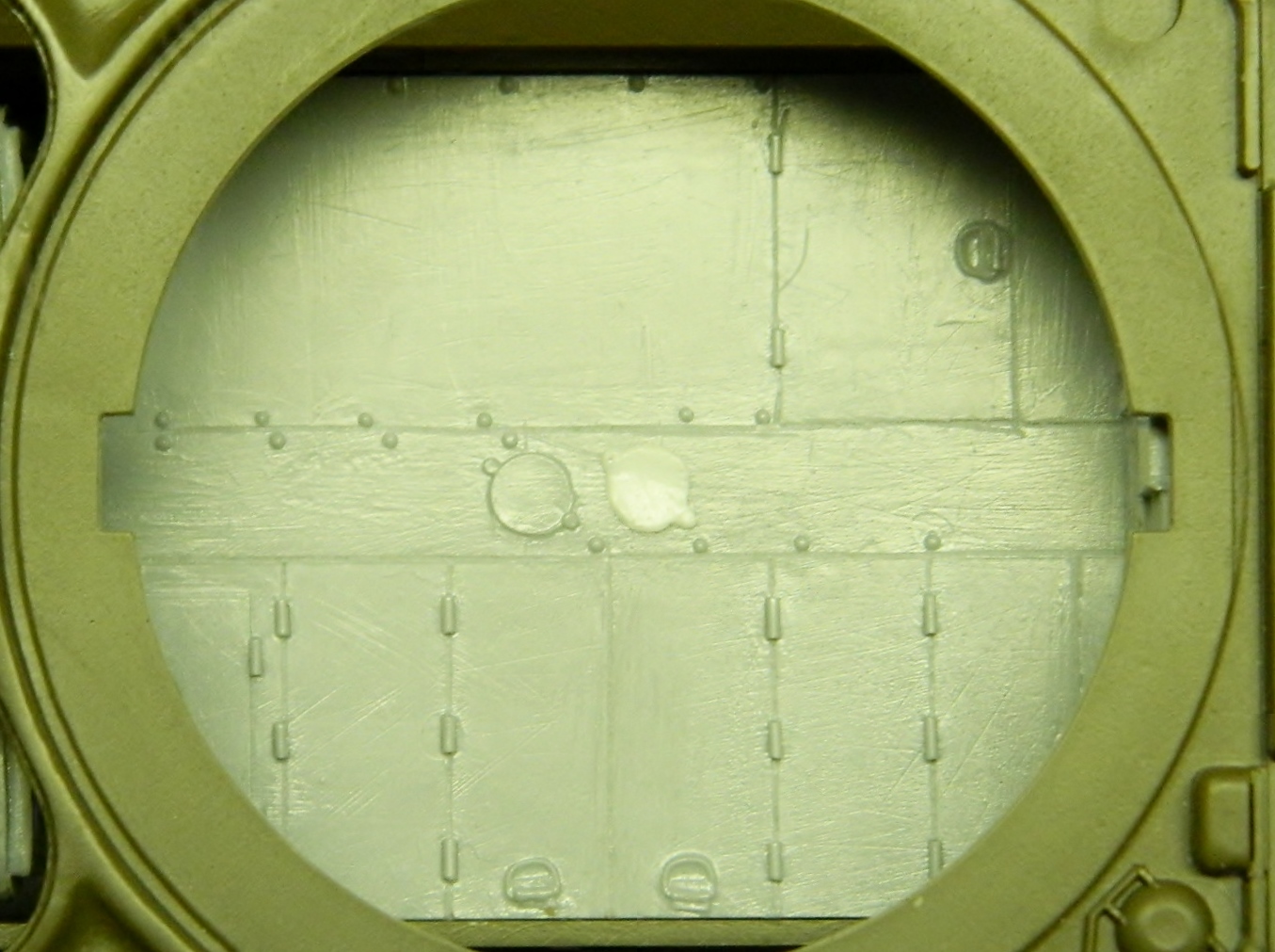
Then I filled it with homemade structural putty that I concocted by dissolving styrene scraps in liquid model cement. The cement works by dissolving the pieces of styrene and once dissolved, the scraps made a gooey plastic that is stronger than commercial filler putty for when strength matters (the goo isn’t as dense as the styrene kit parts but is substantially denser than putty). I used that structural putty to fill the impression in the aluminum (if you’re unwilling to wait overnight for the glue in this solution to evaporate out, you can take THIN shavings of styrene, overfill the depression, and hold the plastic-filled aluminum over a candle, moving it closer until the plastic starts to melt; you’ll have to fiddle with the distance to the flame so the plastic doesn’t get hot enough to char or ignite) (don’t ask how I know this):

The next day after it had cured completely, I popped the new detail out of the foil, and then trimmed, thinned, and glued into a more correct location:


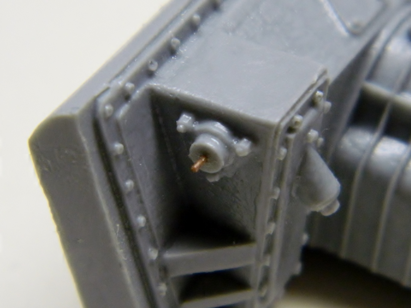
Next I started work on the various details of the control rods, levers, and linkages. Some of these parts are VERY small; all have to be removed from their casting blocks and trimmed before they can be used. I also drilled small holes and installed locating pins made from copper wire to align things and make the bond stronger when they’re glued:


Then the parts are dry-fit to check for fit and alignment (there’s a mistake here with the transverse rod that I didn’t notice at the time; you’ll see how I fixed that later once I realized it):
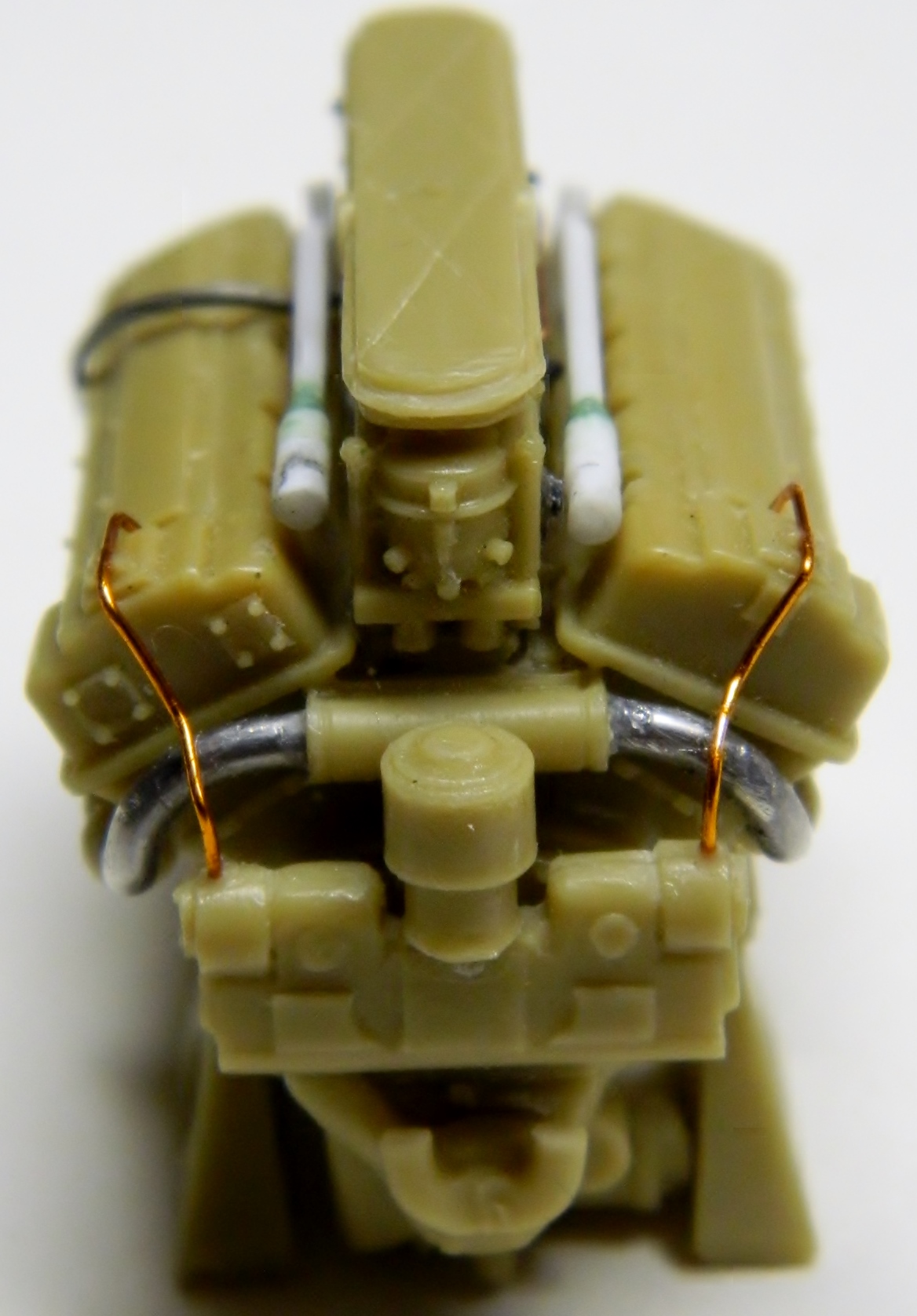
Because there’s only so much of really tiny things that these old eyes will abide at any one sitting (yeah, because those parts are ever so much larger), I went back to the engine and added the throttle linkage that goes to the driver (silver line), the ignition harnesses (copper lines) and the coolant manifolds:


Looking at reference photos, I saw that the floor in front of the driver and co-driver had diamond-tread plate sections, not the smooth floor of the resin part. I made a template out of a 3″ X 5″ (17.62mm X 127mm) card and trimmed it until it was a correct fit and then made a piece out of .020″ (.508mm) sheet styrene:


But the floor in the driver’s area is raised (there are linkage rods, wiring, and other stuff that run underneath it), so I used some blocks of .020″ (.508mm) styrene to raise it:
However, that’s smooth plastic, not diamond-tread. At the time I didn’t know where I could find sheets of diamond-tread in this scale (I do now) so instead I took a floor section from an entirely different kit that does have diamond-tread in this scale (Academy’s M3 Stuart) and using that very thick aluminum foil, I pressed it down on the kit part to copy the tread (using a small hammer and a piece of a bike inner tube to get that foil ALL the way down):


I took the smooth plastic floor I made, glued it onto the patterned foil, trimmed it, and did a dry-fit to check fit and appearance:


So yes…I know I’m crazy. 23 years ago when last I modeled, I used to collect all kinds of strange things because I knew I could use them in a model one day. This is a broken watch I took apart so that I could use the small pieces in a model or two (and yes, has been carried around with me of almost a quarter century because I might need it one day…today is the day):

Where the steering levers attach to the floor are toothed quadrants where the controls can be locked in place to keep the tank from rolling. As it turns out, one of these gears is just the right diameter for what I need, so I cut one into parts, used the old Dymo label tape as guides, and scribed slots for these to fit in:


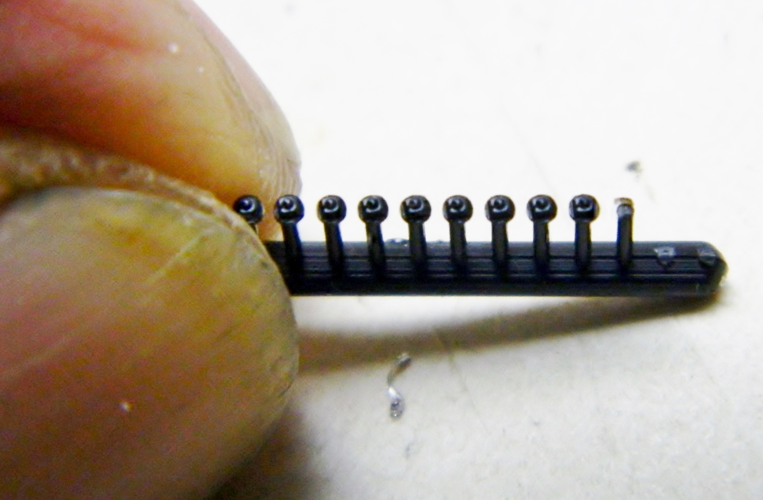
Earlier I had mentioned I was using Grandt Line bolts for details; these are GL bolts (yes, the bolts are square and should be hexagonal – I tried to get the proper ones but though GL has a website, evidently they have no one who will ship an order – I placed one, waited a few days for confirmation, and never heard back despite repeated attempts to evoke any sort of response – it took some doing to find a vendor who sells these items but that took me some time to find – instead of holding up the build I used what I have and they don’t look bad or as wrong as they actually are):
The people who engineered this kit thought that nobody would see interior details which means there are no interior details. But now the interior will show and those details have to be added. The front of the hull on the Sherman tank was its final drive housing, or differential cover (mistakenly called a “transmission cover,” and it’s not; the transmission is inside the tank between the driver and co-driver). That cover/differential/transmission assembly bolted to the hull and those bolts are clearly seen through open hatches (which is how this will be displayed). Since they aren’t there, I had to go to reference photos to see where they are, how they’re spaced, and then put them there. It’s starts with one, one leads to two, and once those were in place, I ran a piece of Dymo label tape between them as a guide and started gluing very small nuts in place, and do that again for the other side (there are a lot more bolts, you’ll see them in subsequent photos):


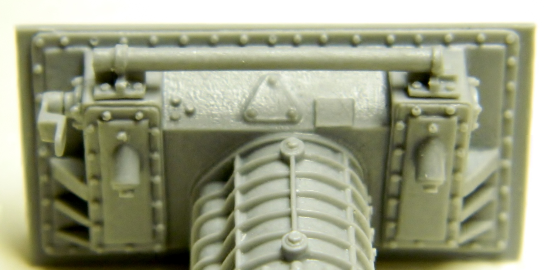
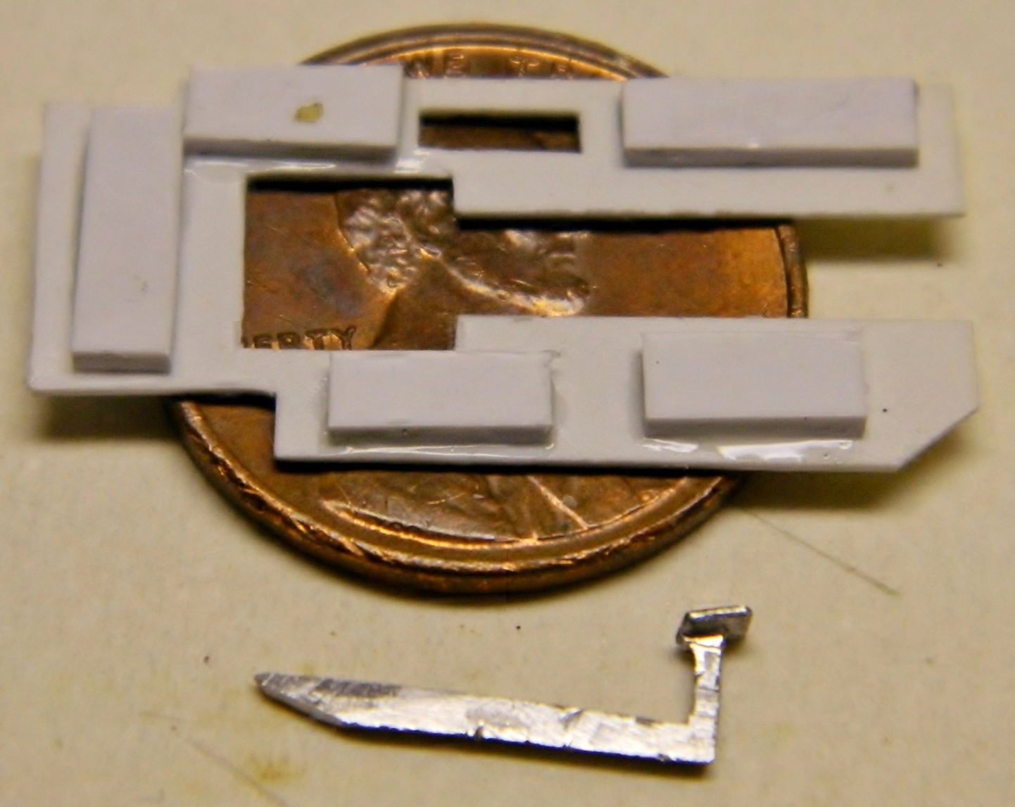
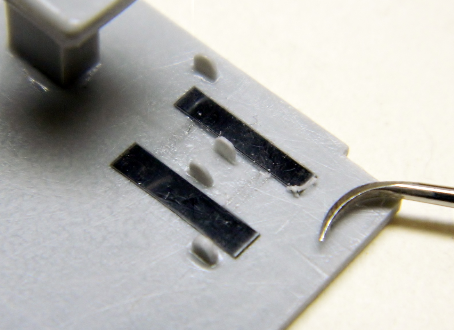
Also visible through open hatches are the bolts that go through the hull and hold the suspension bogies to the sides of the tank. I finally figured out a way to get the spacing correct. Since the spacing of these fasteners are the same on both sides of the hull, I could cut the exterior detail off the donor kit, glue them to the inside of the build kit, and then use putty to hide all that. It starts with cutting the bolt pattern off the donor kit:
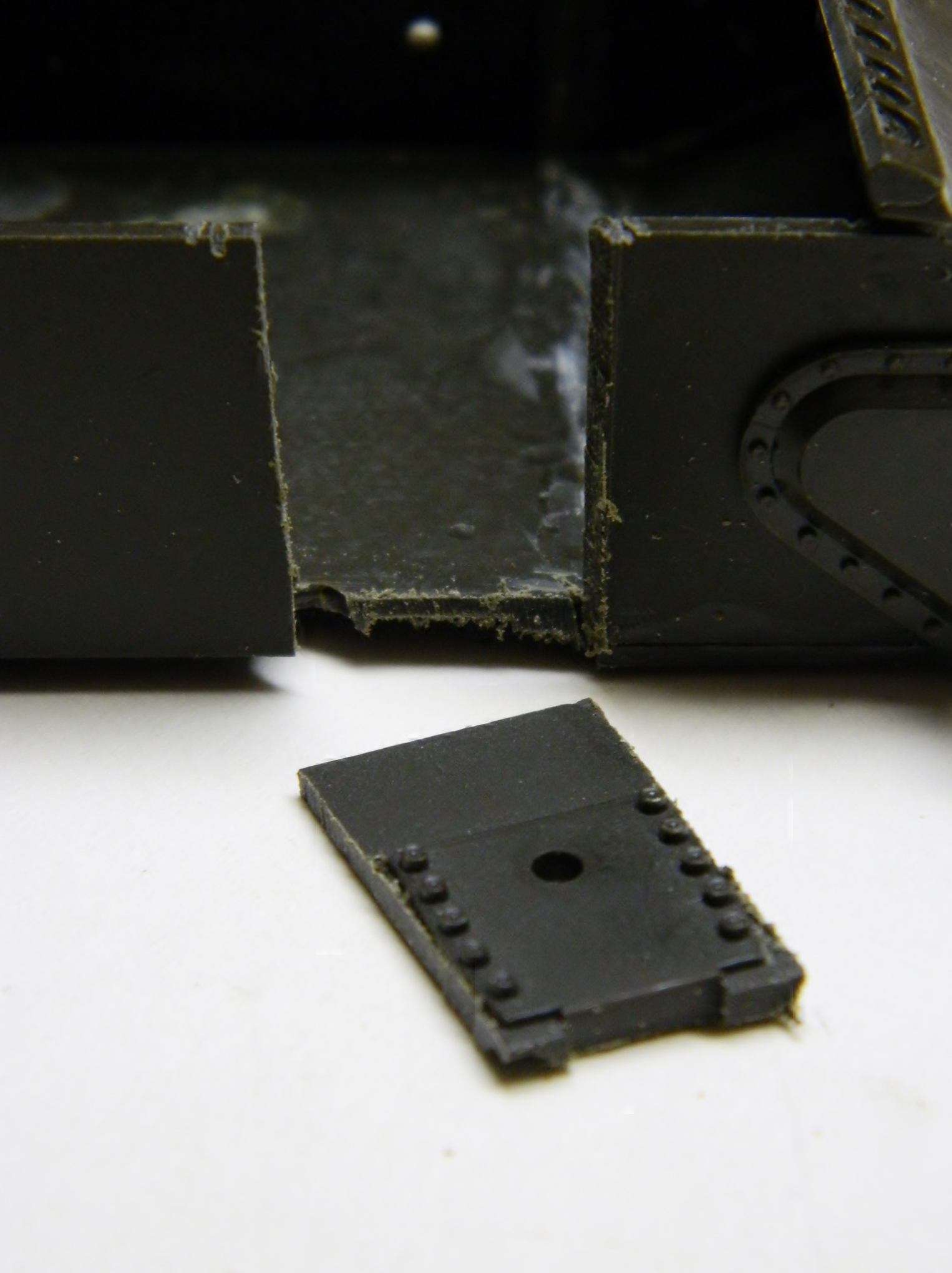
That piece was then filed until it was much thinner and then glued in place, using the hole for alignment and the edges puttied:


There was a bit of work to that, so for the other side, I tried something different. I used less of an addition and only the edges are glued. The center, which is really only there for alignment, I removed easily as it was not glued. Less putty, less putty removal, less work:


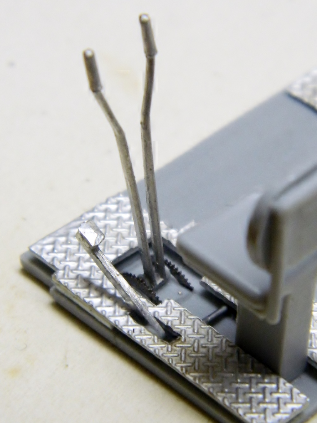
Back to work on the driver’s controls with much sawing of TINY parts, cleaning them up, and getting them to fit with each other. First the steering levers. The old tanks of WWII were steered by slowing down the track on the side you want to turn towards. Want to go left? Apply the brakes to the left track (and tanks are still steered that way, though now the controls are much different). These levers are connected through linkages and rods to brakes inside the differential housing. The AM set provided lead alloy metal parts for some parts and that’s what the steering levers, clutch pedal and arm, and accelerator pedal are (the clutch pedal needed to be reshaped):

Back to cleaning up the really small parts (of which there are more than a lot).
