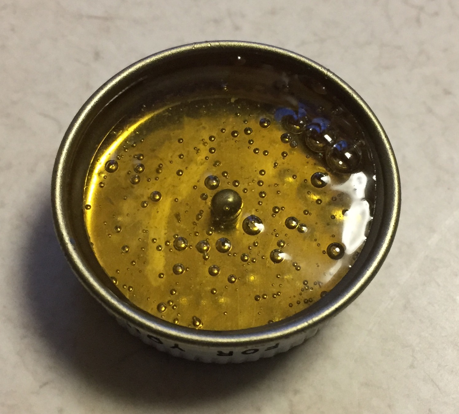
Since I was working on interior parts, I decided to address something that’s been bothering me since I first opened the aftermarket interior set for this model. The instrument panel. Yes, the AM set is A LOT better than the thing the kit provided and I’m pleased to have it. But this is a relatively large scale kit (1/24) and things are easily visible. This is a reference photo of the artificial horizon (of which there are two, one on each panel):

The artificial horizon is the big instrument with the round ball, top half white, bottom half black. As you can see, it’s prominent. This is the PE panel that the AM set provided:

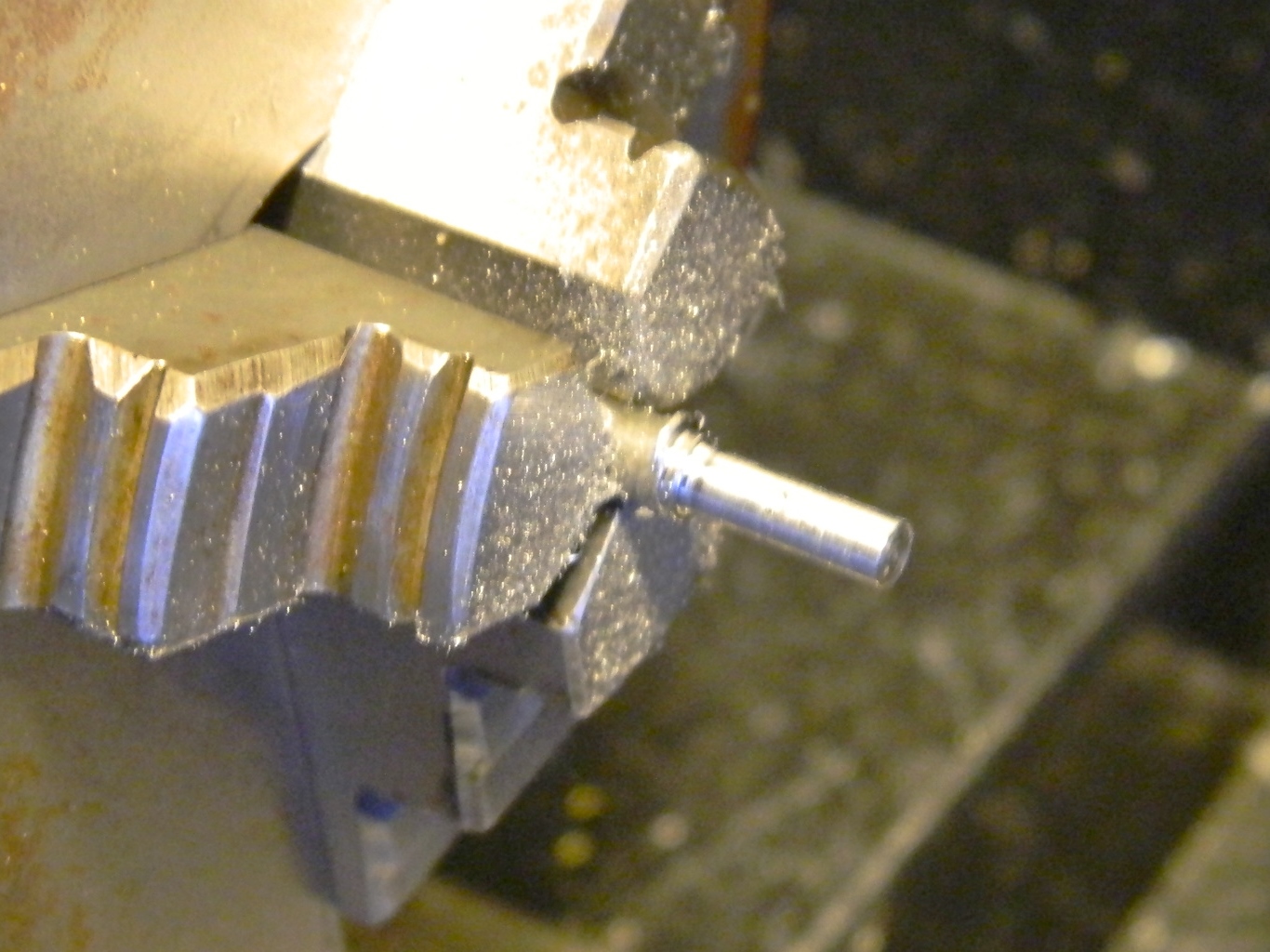
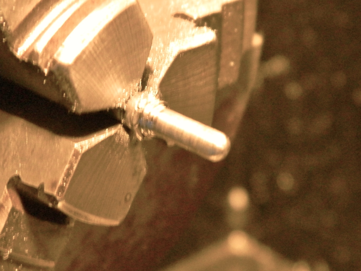
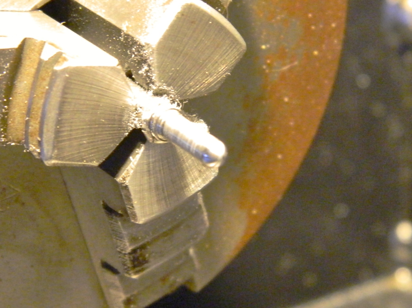
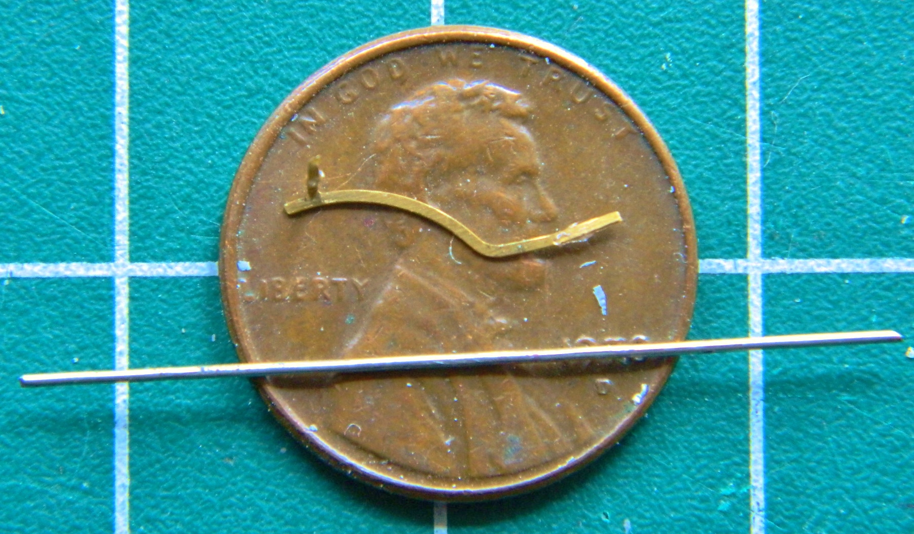
The artificial horizons on these parts are about as convincing as a hooker’s orgasm. I needed to fix that. (The part, not the hooker’s performance. I have my limits, such as they are.) I checked all the parts I have laying around from sword hilt making days, car parts, even model parts, and nothing I had was of the dimension I need. And then I noticed this nail. Its diameter was a little larger than I needed. Okay…I have a lathe. I chucked it into my lathe, turned the diameter down to the dimension required, rounded off the end, polished it a bit, and then cut the part off:

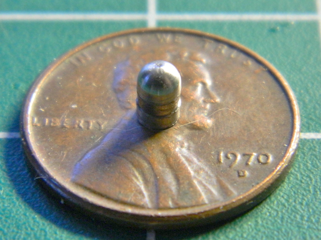
I glued the master (which looks a lot like a scale 40mm grenade to me) into the lid of an empty paint jar and then poured the reusable molding compound over it. Twice:

Now all I had to do was to mix up some resin and pour:
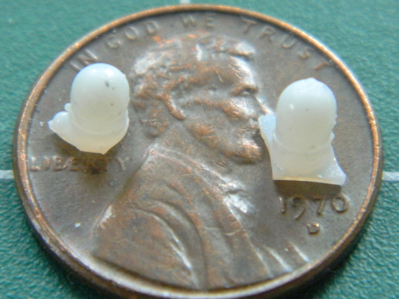
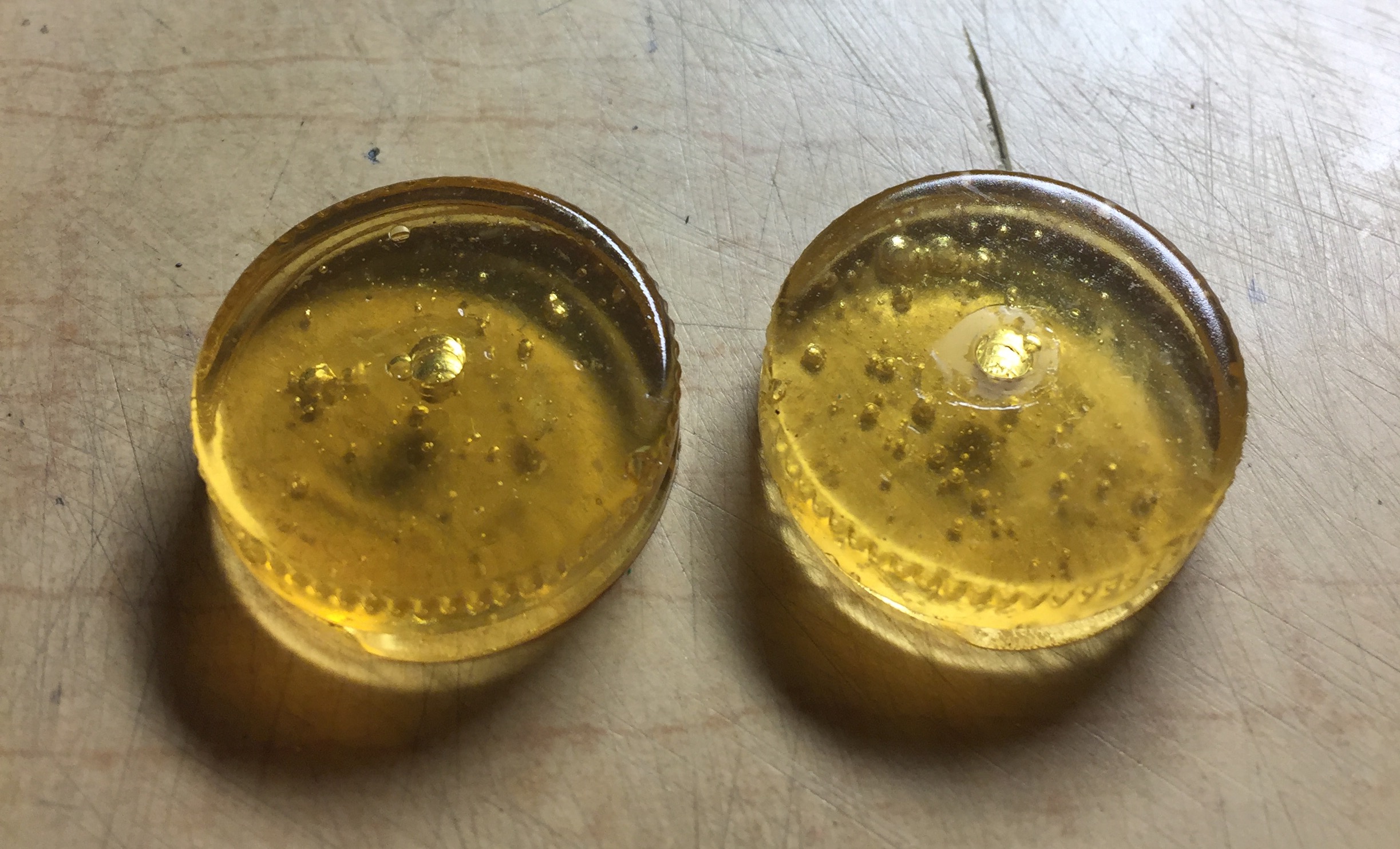
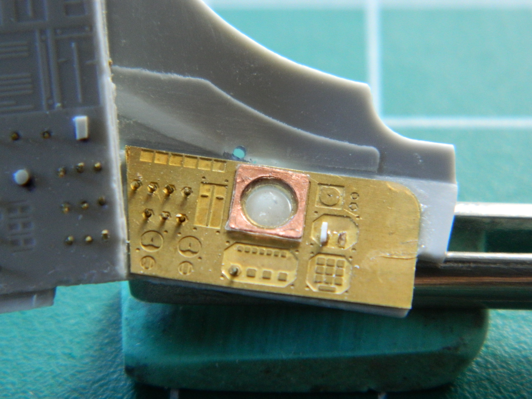
VERY CAUTIOUSLY, I drilled a starter hole in the AM panels, then I used a very fine rat-tail file to open the holes up to the required diameter…and didn’t take any photos of it. ::bangs head on desk:: But as soon as I had the resin copies, I had to try them out (because if they didn’t work, I now had two holes in the part and would have to figure out what to do next). And yeah…I think it worked just fine (CERTAINLY better than what was there!):

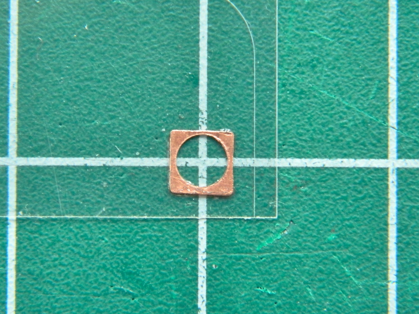
There is a clear front that goes over the artificial horizon, so I made a bezel out of .005″ (.127mm) copper shim stock, used the punch and die set to open the hole, then glued it to a bit of clear acetate. Yeah…once this is painted, it’s going to look just fine:
Now that I’m pleased with the artificial horizon, I realize that all the other gauges on the panels have to be brought up to the same standard. Oh great…NOW what do I do?! I went into my decal stock looking for 1/48 scale instrument face decals. Yeah, the scale is different (1/24 being twice as large as 1/48), but the physical dimensions of the decals are just perfect for this build, so that’s what I’ll use. With only one exception, which I can easily work around, I even have the type of instrument faces I need! When time comes to start throwing paint is when I’ll install the instrument decals.
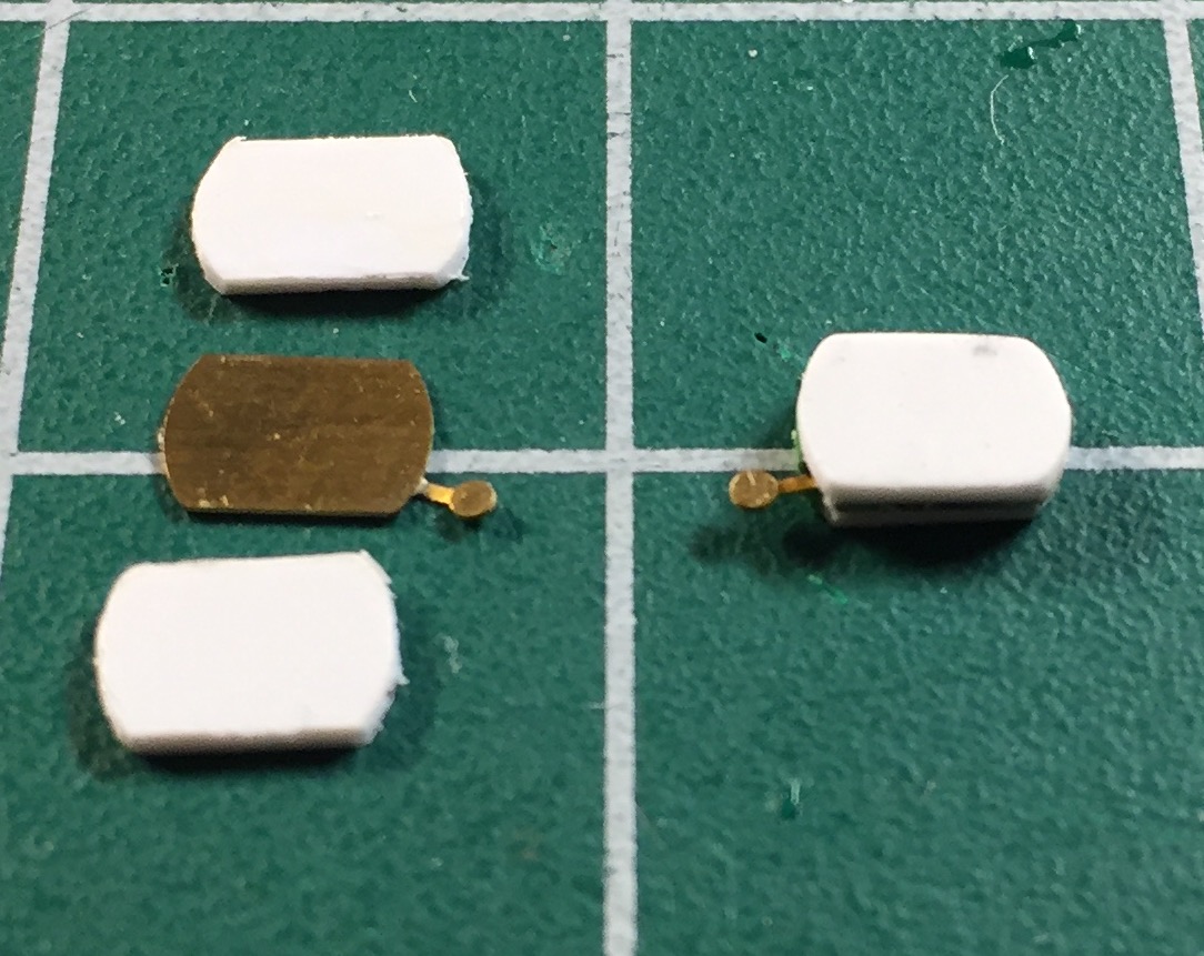
Moving to the sides of the cabin, it was time to start making the other details that belong there. The AM set had the oxygen control boxes for the sides, it’s just that they’re WAY too thin to use as-is. I used .020″ (.508mm) stock to thicken them to the proper size:
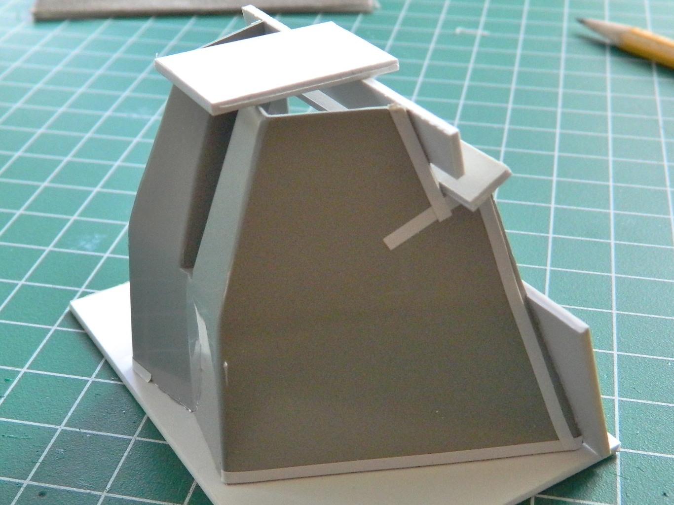
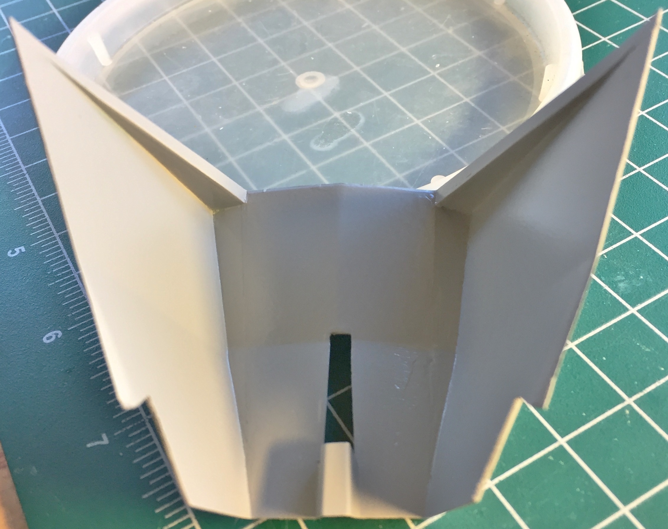
Then I dry-fit them to the cabin walls. You remember the cabin walls? The ones I had to move to make room for the seats? Well…I got the dimensions wrong. WRONG. Yes, I’m quite familiar with “measure [insert number here], cut once.” I thought I had done that! In fact, I’d done that A LOT. And each time I made the same error. If you look at the photo below, I’m sure you’ll see the error much sooner than I did… The right side is taller than the left side by about a quarter inch (5.08mm):
And no…I have no idea how I made such a fundamental error (if I knew that, I wouldn’t have made the error).
Okay, then, how do we fix this? By this point I’d discovered how fragile the part that forms the inner cabin walls really is. I’m not ham-handed and I still had to glue this damned thing back together four times. So that means I’m not going to be able to redo the part I have. Okay, so how about scratch-building a new cabin wall assembly? Uhm…no. This part, though comprised of flat panels, has some pretty funky angles to it. Could I scratch-build this part? Yeah, I could. But to get it right would take time. It would take a lot of time. Normally I’d shrug at that idea and have at it. But I’m trying to get this model ready to bring to a show on April 29…and there’s LOTS left to do and I’m not sure I have that time. How the hell do I get another cabin wall part?
I go to eBay and buy another kit. And that’s what I did.
It’s not like I don’t have anything else to work on while I’m waiting for the second kit to arrive!
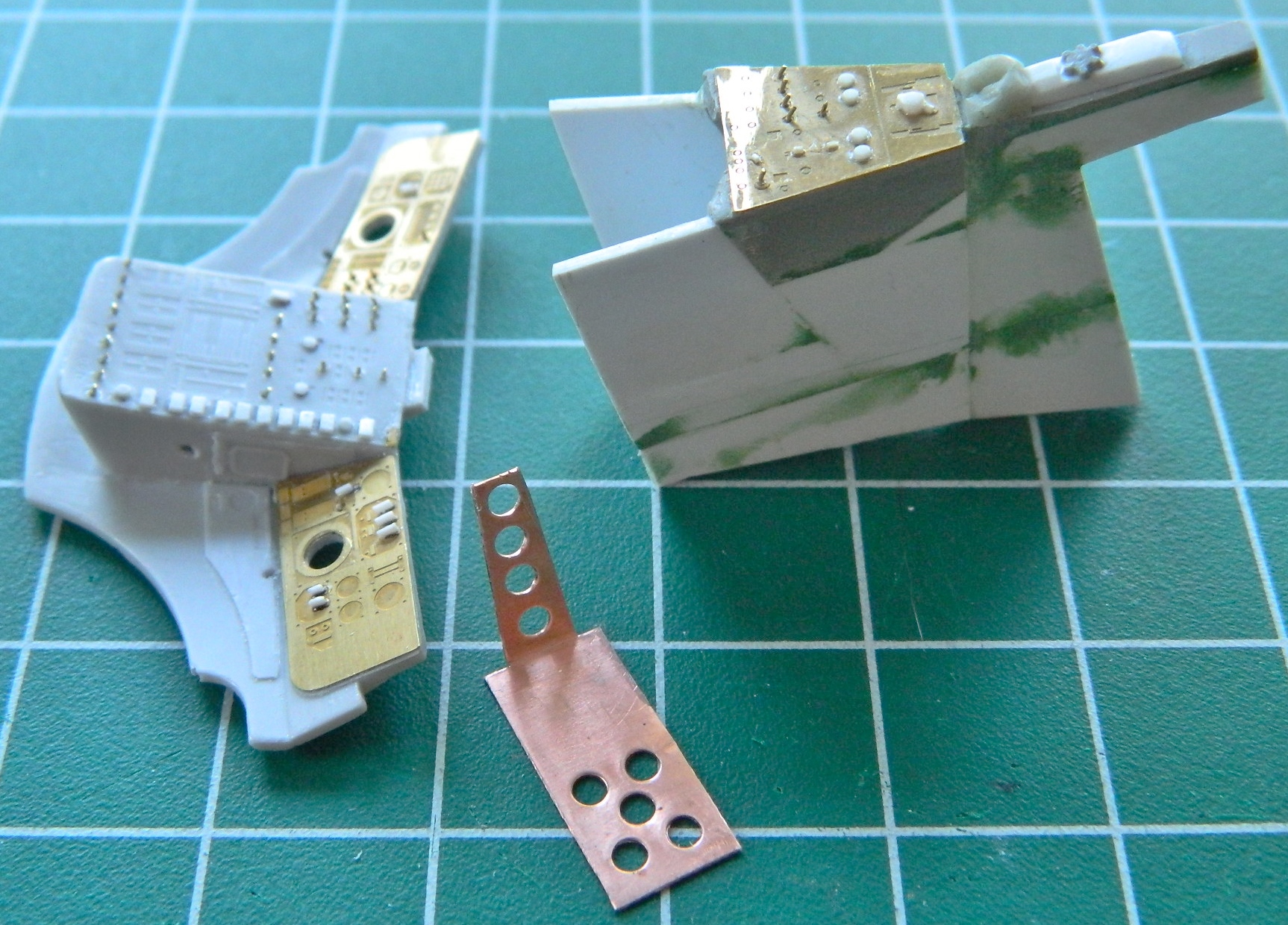
Dry-fitting the cabin parts has been “interesting,” in the most Chinese sense of the word. I decided to make things easier on myself (if only for the novelty of that). I’ve been having serious problems with getting the instrument panel to stay attached to the center console. The problem with that is that there is such a small surface for any adhesive to work on that any nudge or torque, no matter how small or gentle, causes the two parts to separate. I needed something more robust. What I did was take a section of .010″ (.254mm) shim-stock, punch holes in it for better adhesive adhesion, and using Shoe Goo (great stuff, that!) I attached the support bracket to the underside of the console:

That also eased dry-fitting the parts. The only point of reference I have is where the instrument panel attaches to the walls of the cabin. Rather than permanently attach the panel to the support, I taped it in place and used that as my reference to finish fitting the console to the cabin (even though the sides are wrong, the floor isn’t and that’s what the console with its added sides need to fit to). I used a lot of pieces to build up the sides and I needed to check the seams to make sure they won’t be visible. I used a rattle-can with what I thought was acrylic primer (there will be more on this later on) to show the seams…and show them it did. The surfaces got sanded, puttied, sanded, and puttied again, until the added sections were, well, seamless:

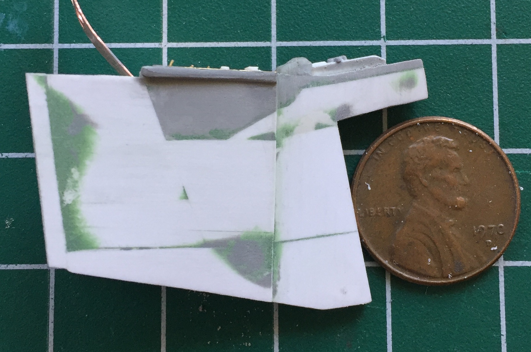
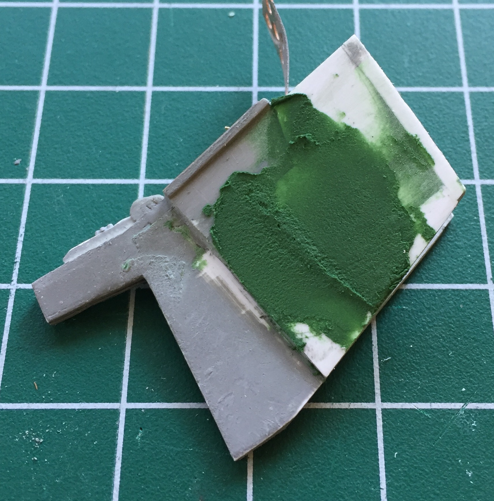
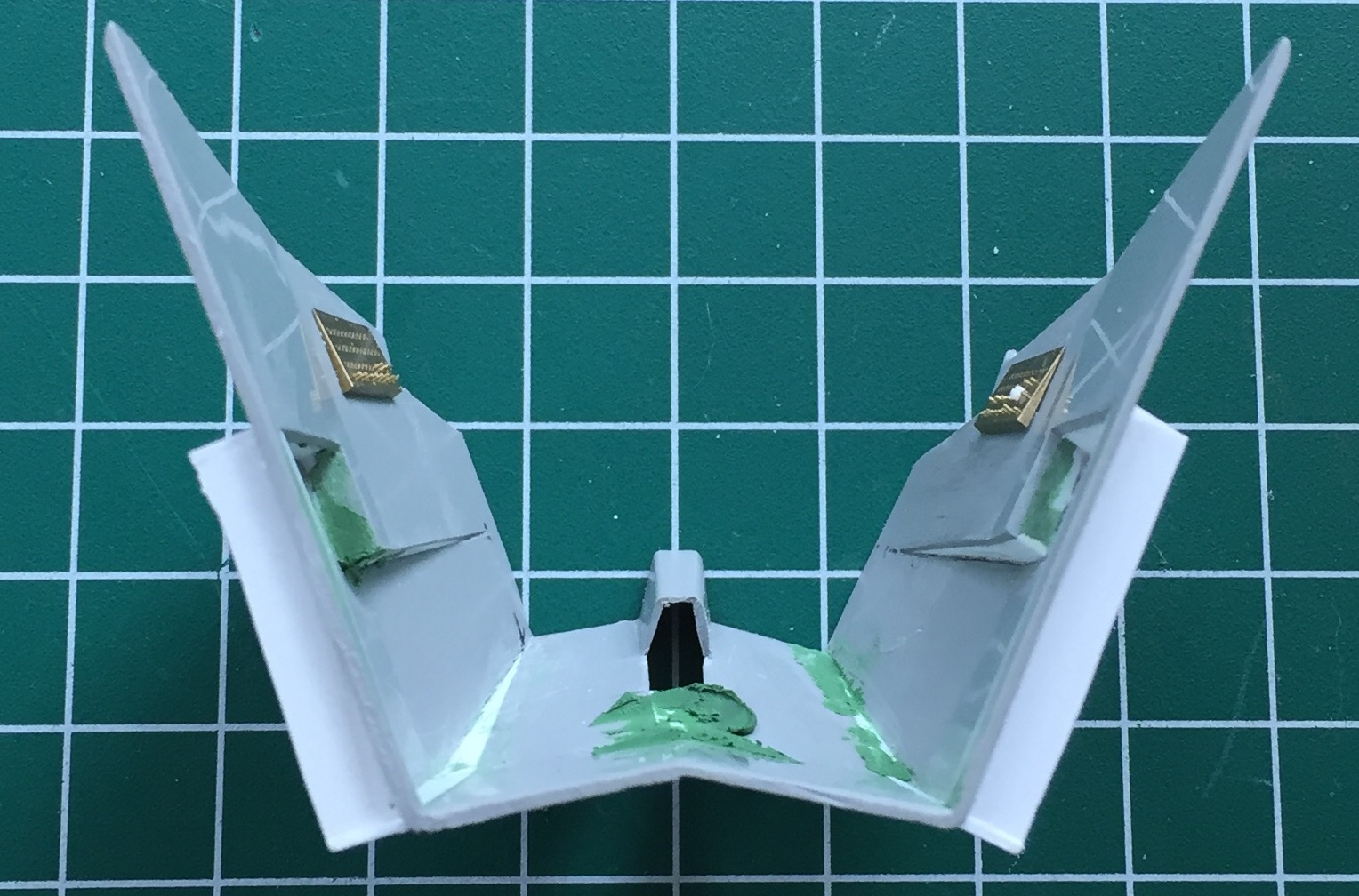
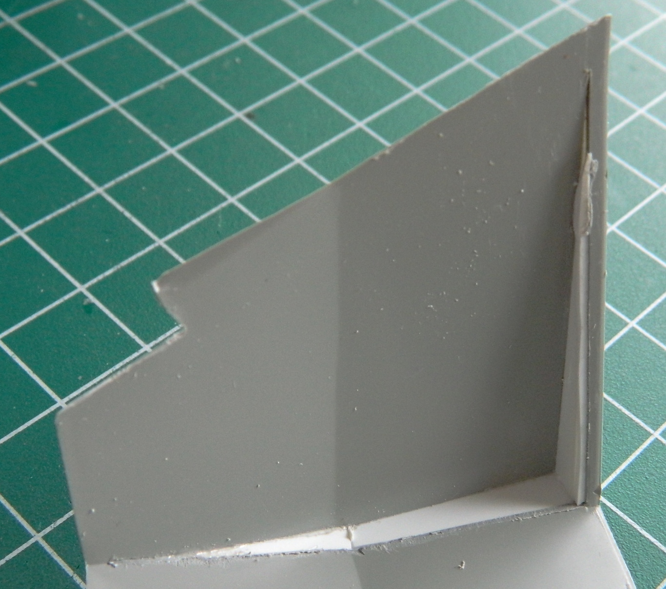
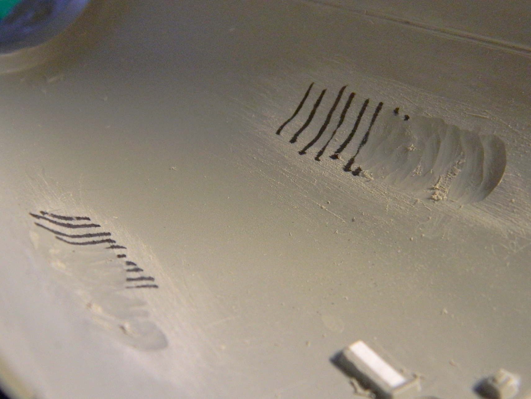
An area that I knew needed work was the channel between the hatches. This is where the bridle for the parachutes was stowed and as such it needed to be flat. As you can see, it wasn’t:
After working on it and getting it suitably flat (I thought…once again I was in error), I needed to see just how far towards the nose of the capsule this channel went. Finally getting the hint about checking references, I checked references:

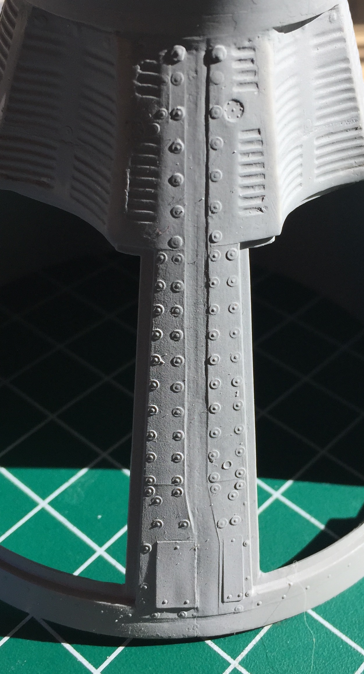
Yep…it goes all the way to the point where the nose starts to taper. In the above photo, note the white stripe where it crosses the cylindrical section. See those flat tiles on either side of it? Compare it to these photos:
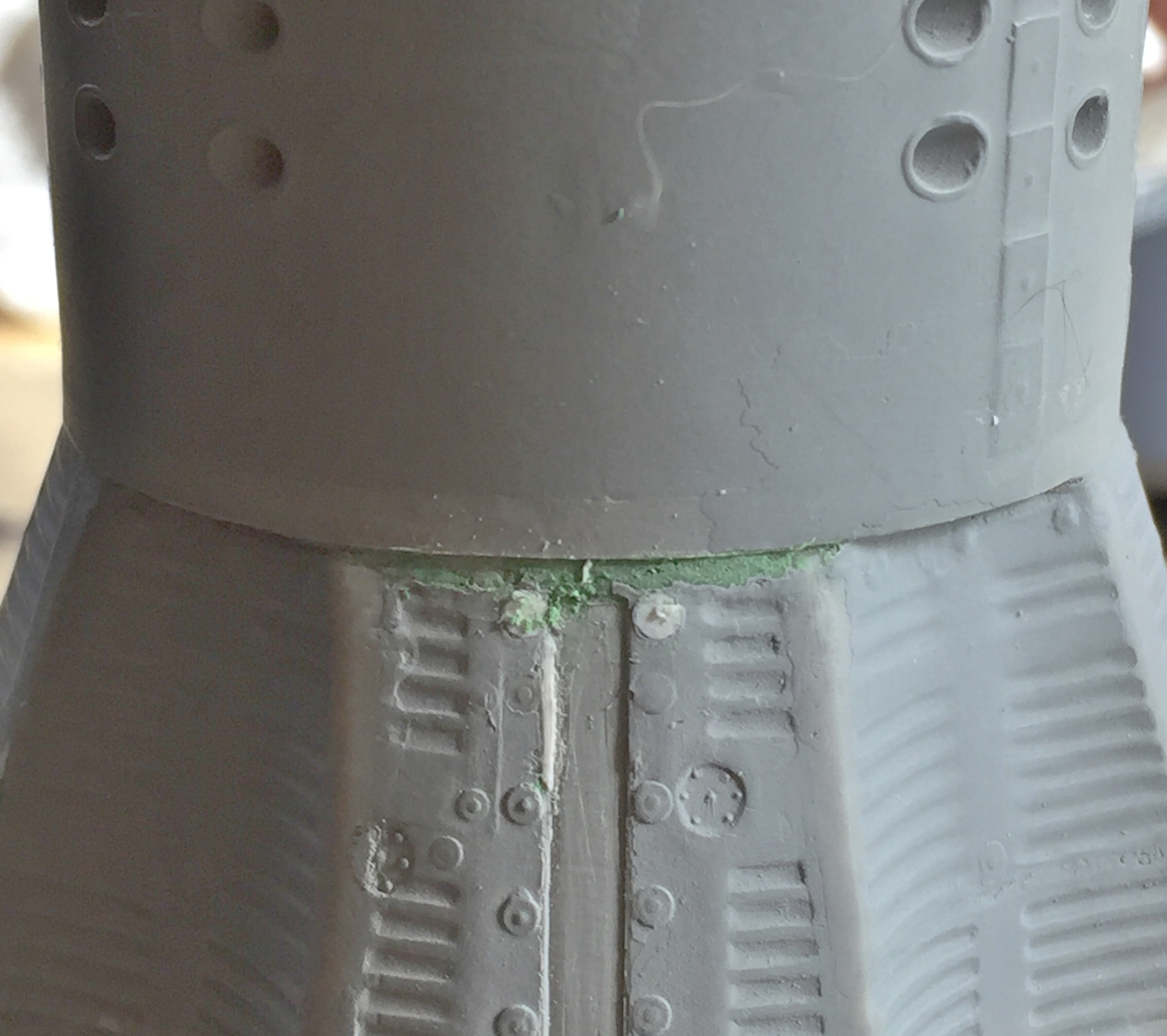

At the end of the channel where the cylindrical section meets the conical section, there are no tiles! Hmm… So I rotated the hull to see if they were there at all. Yes, they’re there. They’re 90-degrees away from where they’re supposed to be. Oh great. Another error. How the aerial intercourse did I manage to put that part 90-degrees off?! Well as it turned out, it was easy. The locating tab and slot are in the wrong place! Now, when I glue something on, I goddamned well glue something sodding on! There’s no way I’m going to be able to remove the cylindrical section without destroying it. Aw, damn…if I only had another kit.
Oh. Wait. I don’t have it yet, but it’s on the way! Whew… So that gets set aside for now.
There were a few details provided on the PE fret of the AM set that I didn’t like. PE parts are flat. The details they replicate aren’t flat at all and the difference nagged at me sufficiently that I knew at some point I’d have to make new details. Okay, looks like “some point” has arrived.
On both side of the seats are handholds. Living at the bottom of a gravity well the way we do, there are ALL types of unconscious assumptions we make that do not hold true in a micro-gravity environment. In micro-gravity, there is no “just sit down” possible. Gravity is what makes us able to “just sit down.” In micro-gravity, if you want to plant your ass in a seat (and the inside of a Gemini capsule was so small, you had to plant that aforementioned ass someplace to allow room to breathe), you have to pull your ass to where you want it and then strap it to that location. So the clever engineers at McDonnell (the contractor who built the Gemini capsules) made handholds for just that purpose. They mount on gimbals to the sides of the seats so they can be rotated out of the way once the ass(es) were strapped into the only place they’d fit. The seats.
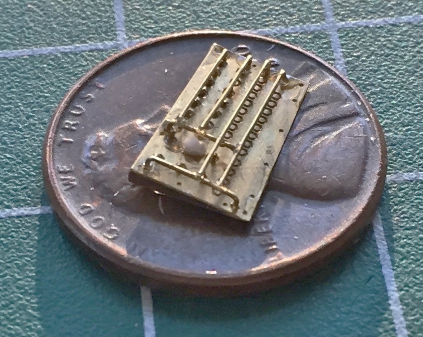
There’s also grab-bars above the instrument panel which the PE set has. They’re flat, too, and they shouldn’t be. 24 gauge copper wire was bent and soldered to replace the flat PE details (the flat details are shown to illustrate the differences). When you’re forming something, even something as simple as a curve to a wire, you’ll find the shape you need in the strangest places. To get the curve accurate for the grab bars, I used the pein end of a small ball pein hammer as my form (buck). I used the shank of a drill bit to form the seat-mounted grab handles:


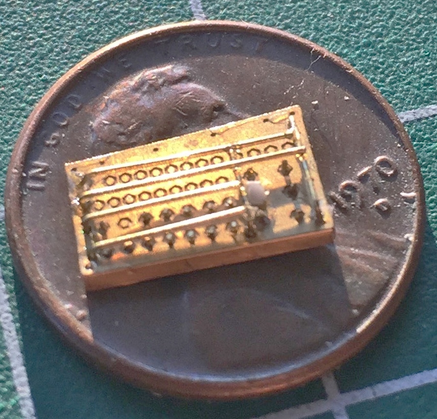
Since I was on a bagel (which is much like a roll, only firmer), I decided to add the safety bars to the side switch panels. (In the process I also decided that I’m a lot crazier than I realized!) (Those of you who know me even moderately well probably wonder why it’s taken me so long to realize that. Simple. I try to pay as little attention to that maniac as I can manage!) Adding the safety bars, 26 gauge wire, was tedious. It was maddening. I’m also not 100% happy with how they’ve turned out. But they do fall within the 90-95% tolerance I allow myself so this is as they will be (and no, I’m not looking forward to having to paint all those switches and buttons that are underneath the bars, but adding the bars after the panels have all been painted wouldn’t work…paint interferes with glue adhesion, so…). This is the panel for the right side:
And this is the panel for the left, command, side:

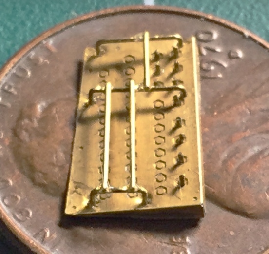
I tried to solder them correctly but there was no way that was working. Solder this and the heat unsolders that. Okay…so the bars don’t butt the way they’re supposed to. 90-95%.
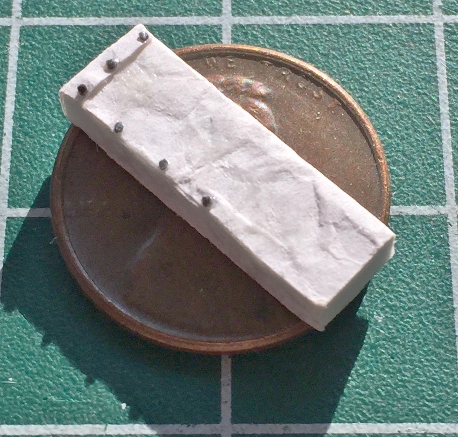
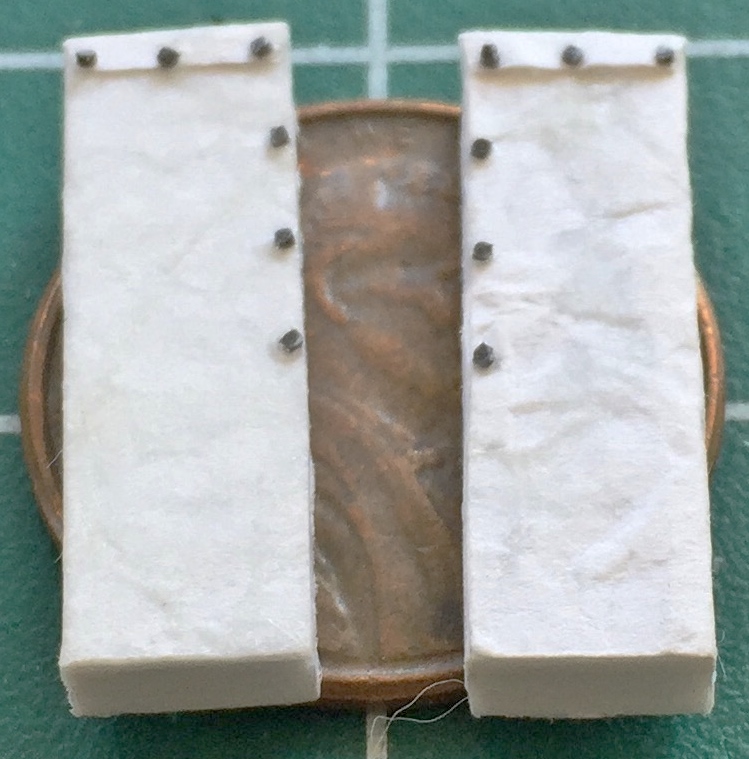
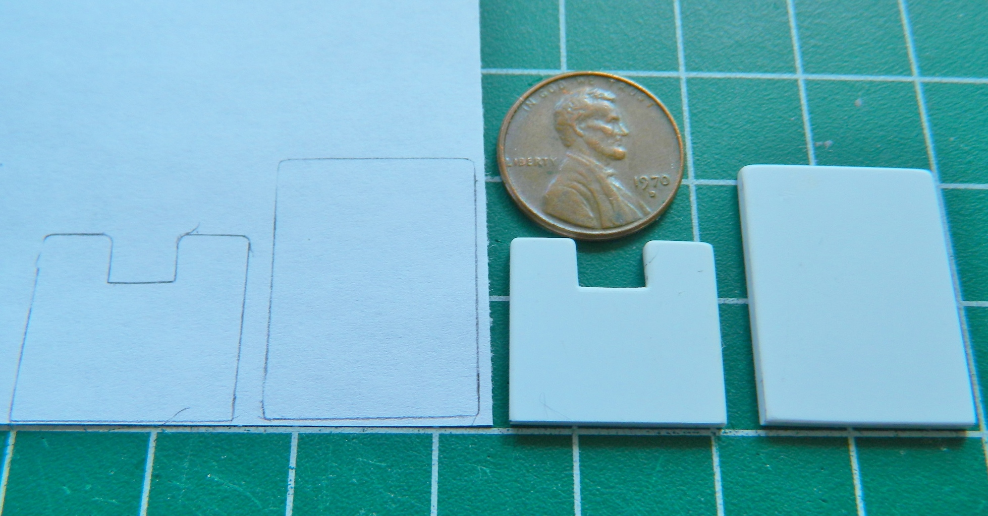
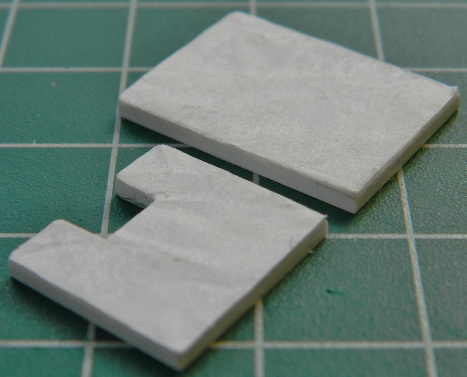
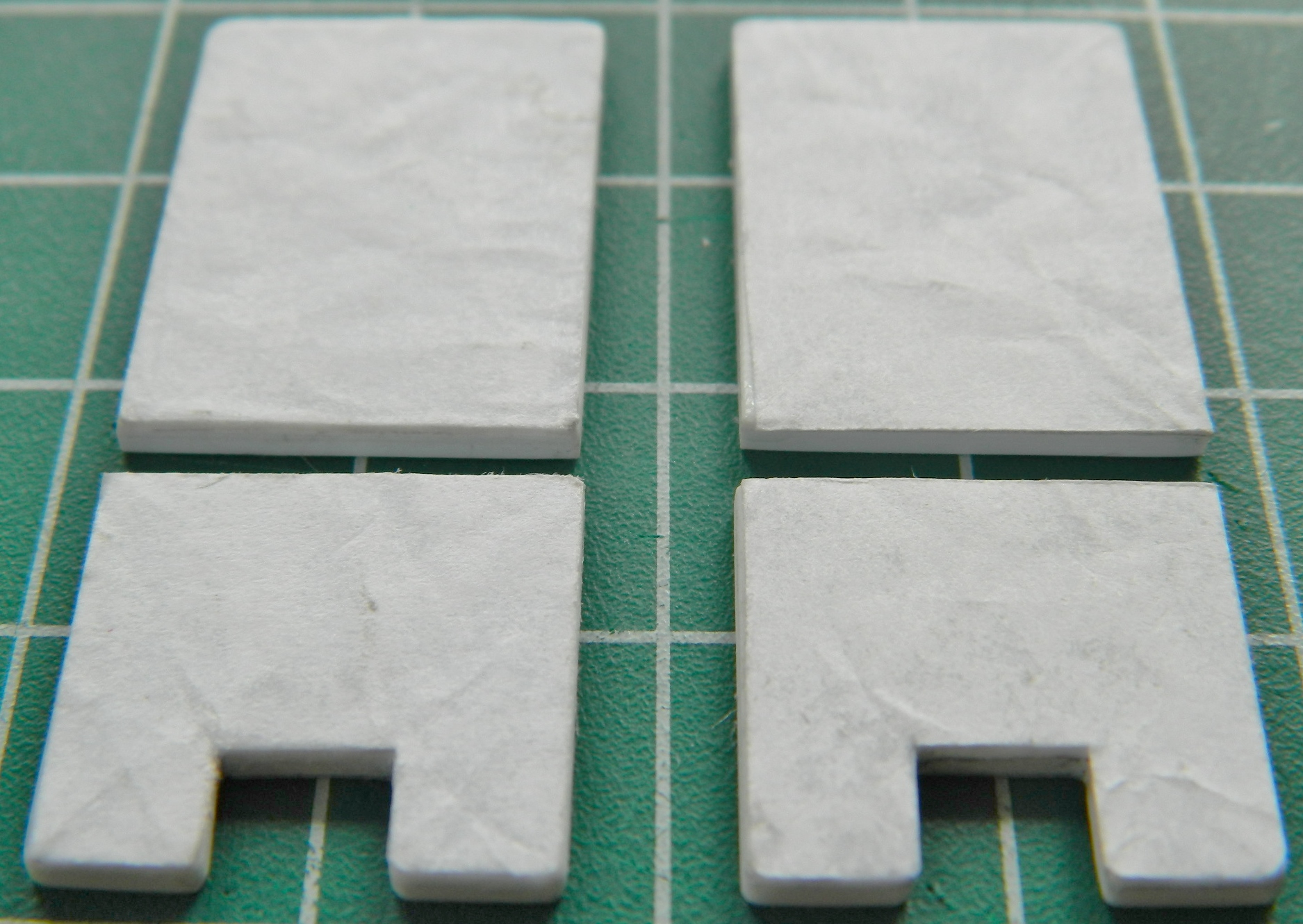
There are also containers for the various pieces of gear on the LDF (long-duration flights), there’s even a fecal collection bag. (Yeah…those astronauts kept their shit together!) The capsule I’m modeling didn’t engage in an LDF so I don’t need the collection bags. (And I don’t EVEN want to know how the hell they took a dump in such confined spaces! I’m sure the crew ended up knowing MUCH MORE about each other than they ever wanted to know. And the smell must’ve…nah…let’s not go there.) The gear bags were fabric so the absolutely smooth surfaces of plastic were not acceptable. Attempts to carve/scrape folds onto the surfaces was equally unacceptable. I didn’t want to use the texture I’d already used (more on that in the next post), instead I used a piece of printer paper, crumpled it a bit, and glued it to the surface of the plastic block and added very small bits of plastic for the snaps that held the real ones closed:

I was so pleased with how that worked that I decided to solve another problem I had, how to texture the seat cushions. More printer paper, strategically folded. I think the edges of the paper will replicate the seams nicely:
And then the second kit arrived:

One of the problems I created for myself the first time I moved the cabin’s sides out was how to adapt the details that belong there with a surface that didn’t have that depression. This time I decided to move the entire wall out. But the same restrictions applied. I couldn’t alter the location of the upper edges of the cabin walls. They need to fit inside a specific space. So to move the entire wall, I had to fix the critical dimensions so that they wouldn’t move. I did this by gluing flat .060″ (1.524mm) stock in place to keep the critical dimensions from shifting once structure was cut. My initial thought was to move all of the walls out so I used 2mm plastic masking tape to outline the areas that could not be altered:

Then I decided that since I had everything so well braced, I didn’t need to make more than two cuts; one down the back and one across the bottom where the sides meet the floor:

The added bracing snapped off easily with no damage to the part. I checked the fit of where the rear of the cabin meets the rear bulkhead and so far so good:
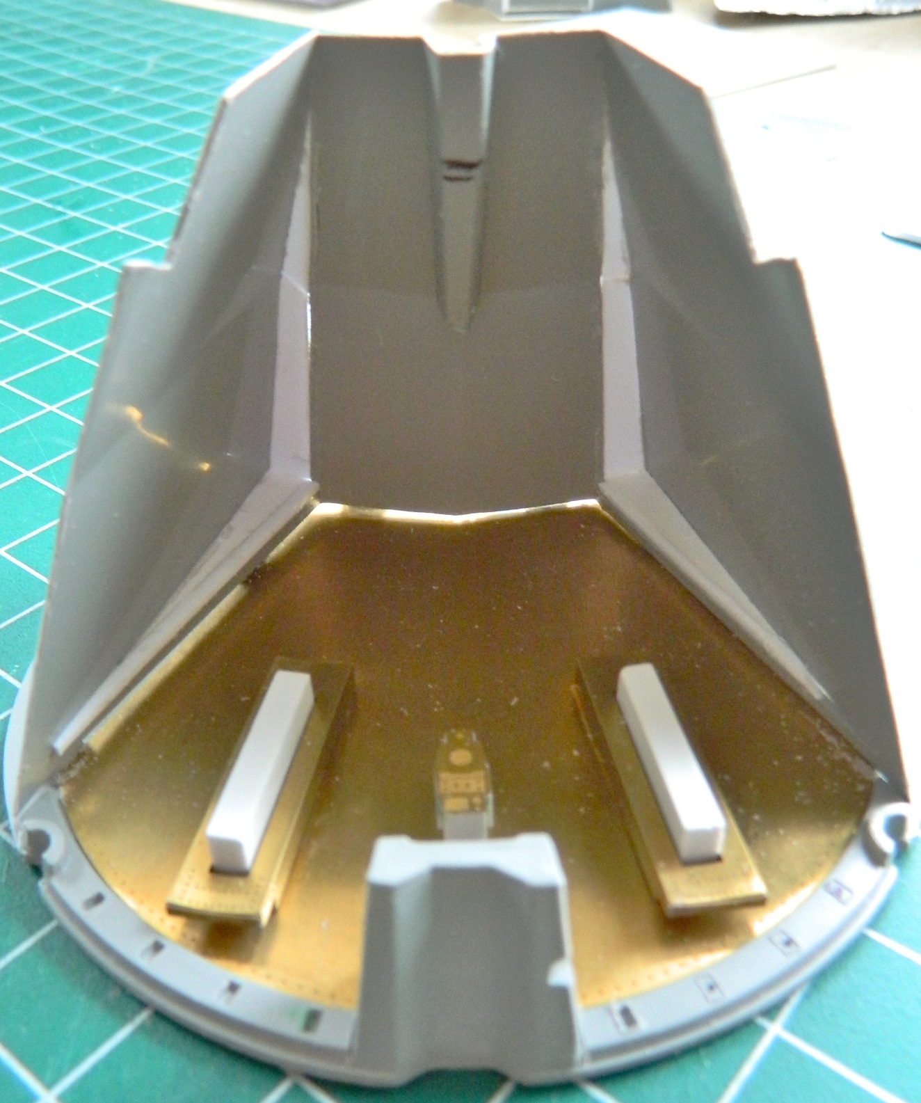
Then I slipped the hull over the taped-together cabin/bulkhead parts…and discovered I’d made another problem for myself that I needed to solve. Y’see, I decided to get clever. Yes…the distance I moved the first walls worked, but it was just still a bit too snug for the details I have yet to add to fit in there. So, clever monkey that I can be, I moved these walls out just a wee bit further. Further enough so that the cabin would now not fit inside the exterior! Well, I was NOT going to buy another kit again! I’m going to make THIS one fit…and I did. That was accomplished by sanding away as much of the addition’s corners and edges that I could without sanding all the way through (and it was close…it was very, very, close). Test fitting showed me I was on the correct path, I just needed more room. Thankfully these old kits often have very thick walls and this one could be the poster-kit for that. The Dremel tool allowed me to remove just enough from the inside of the outer part for this new and improved cabin assembly to fit. Barely:
Then I primed the cabin interior with what I thought was acrylic primer. The primer showed me that the joins of the wall extensions needed a little more finishing:
Rather than have fresh primer gum up my sandpaper, I decided to wash the primer away. If you don’t let acrylic paints set long enough to fully cure (a couple of weeks, then it’s not as easy to remove), it can be washed away with soapy water and a toothbrush (preferably an old one you’re not using anymore, but hey…it’s your mouth, so…).
It didn’t wash away. In fact, it acted just like enamel! The reason for that is because the primer IS enamel! ::bangs head on desk:: (Again.) Well…okay, I know what can remove enamel. Turpentine!
Well…there’s a problem with that. As I discovered, turpentine attacks the plastic and makes the surface gummy. Oh. Groovy (yes, I’m that old). I let the turpentine evaporate and the surface, albeit with a texture imparted by a paper towel, hardened. Then I used enamel thinner to remove the enamel primer. It also attacked the surface of the plastic with the same result. Well. Since I’m going to have to sand the entire surface of the cabin’s interior anyway, so much for a supposed short cut. I waited for the plastic to harden again and sanded the bastard smooth.
Now there is no discernible line where the addition meets the floor.

With regard to the side panel switch guards, I would have suggested masking off just the attachment zones, then paint the panel and all the switches, then just add the guard rails and paint the rest.
LikeLike