Tamiya makes an adequate kit of the A3 and this is the base for this build:


Since I haven’t done a model since 1991 and I wanted to ease back into the pastime, I decided I would add a COMPLETE interior to a kit that was never designed to have one. This means adding an engine and engine bay, a crew compartment, and all the turret details, not any of which were engineered to work with each other. (Let’s start easy, eh?)
One of the (many) things I discovered is that not only is the state of the art for after-market (AM) detail sets MUCH different than it was 24 years ago, so is the Internet. I can find references (photographic and written) that were unavailable Back Then. So unlike Back Then, I don’t have to scratch build everything I want to add (as in, start with a pile of bits to make all the gizmos that a tank is full of).
So I started with the engine bay. There’s a Belgian company, Verlinden, that makes really beautifully-modeled AM sets for all sorts of models and one of them is the Ford engine. From the box art:

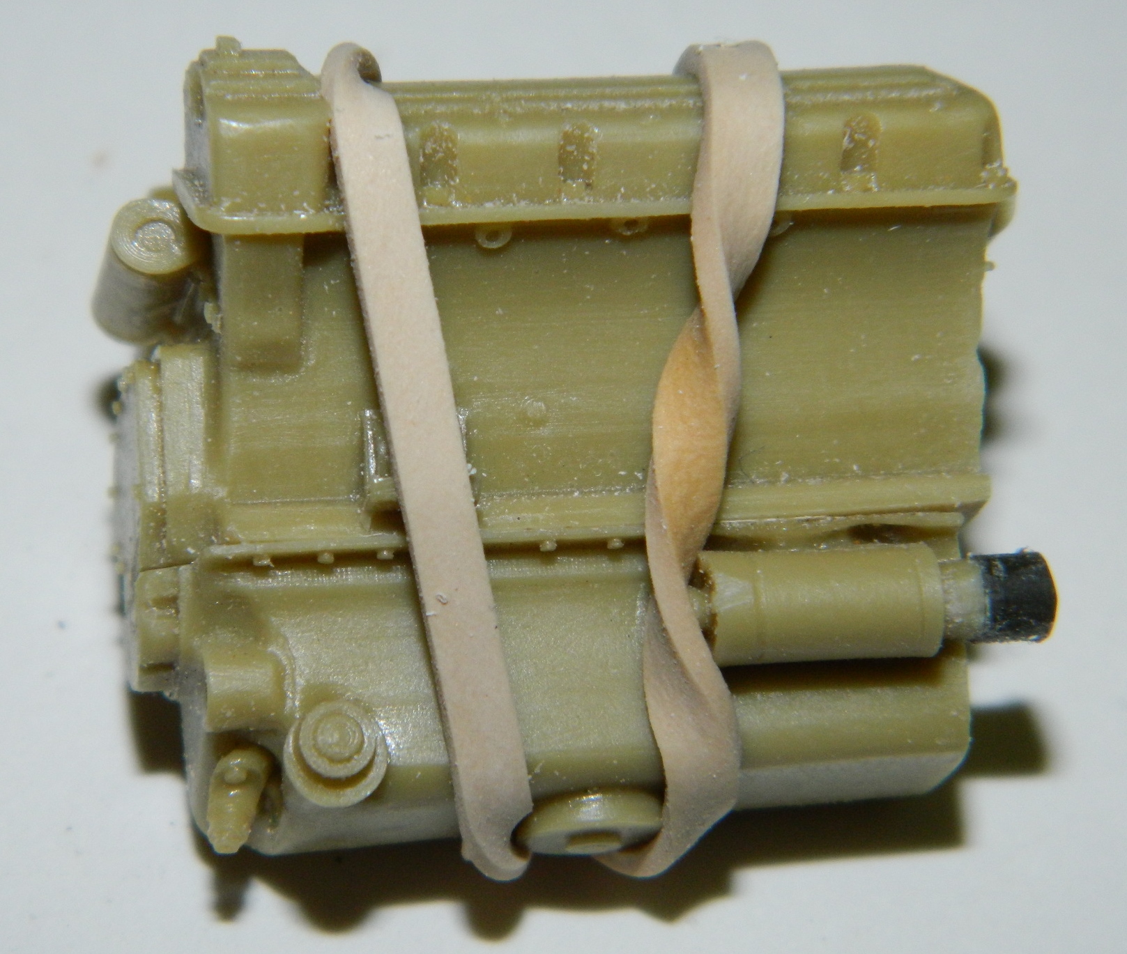
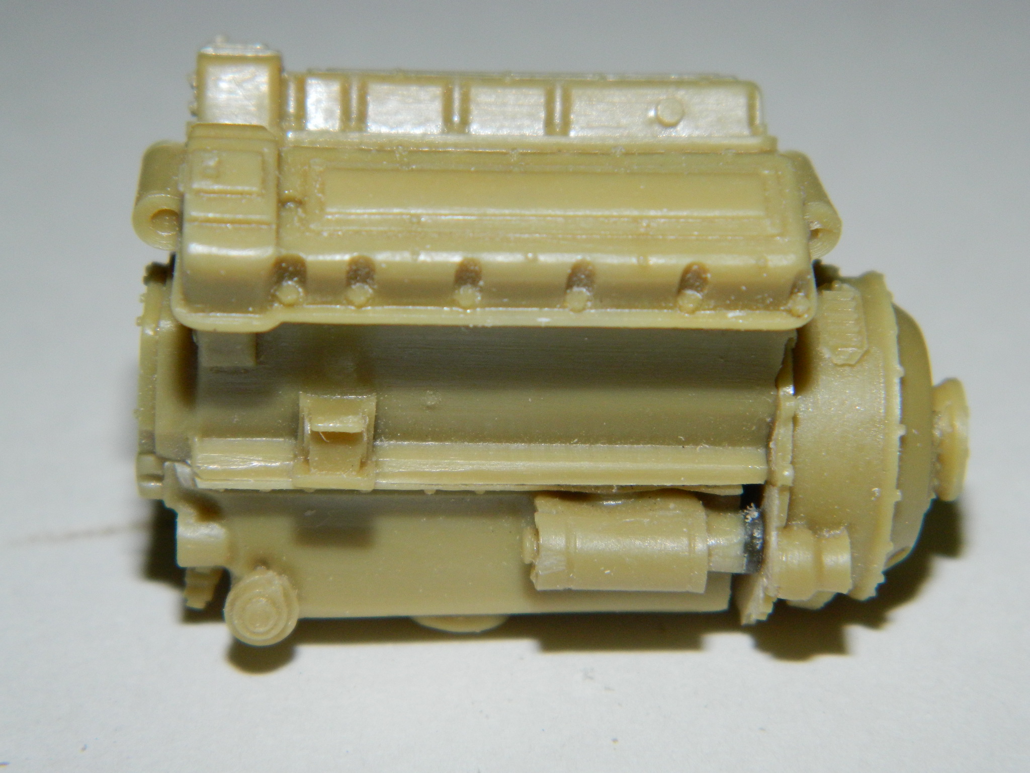
Most of the parts are resin (works about the same as fingernails) and this shows what the AM set includes:

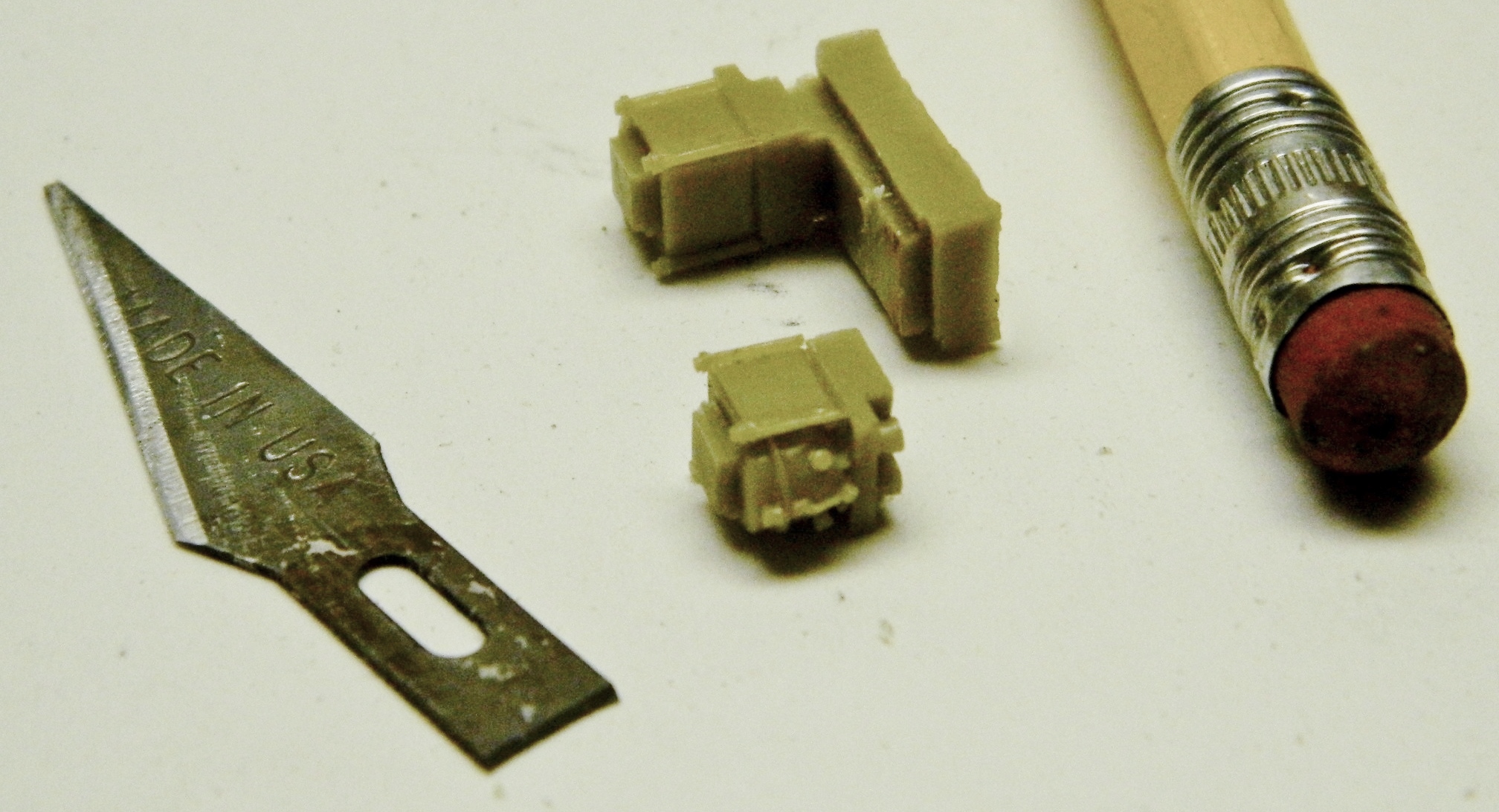
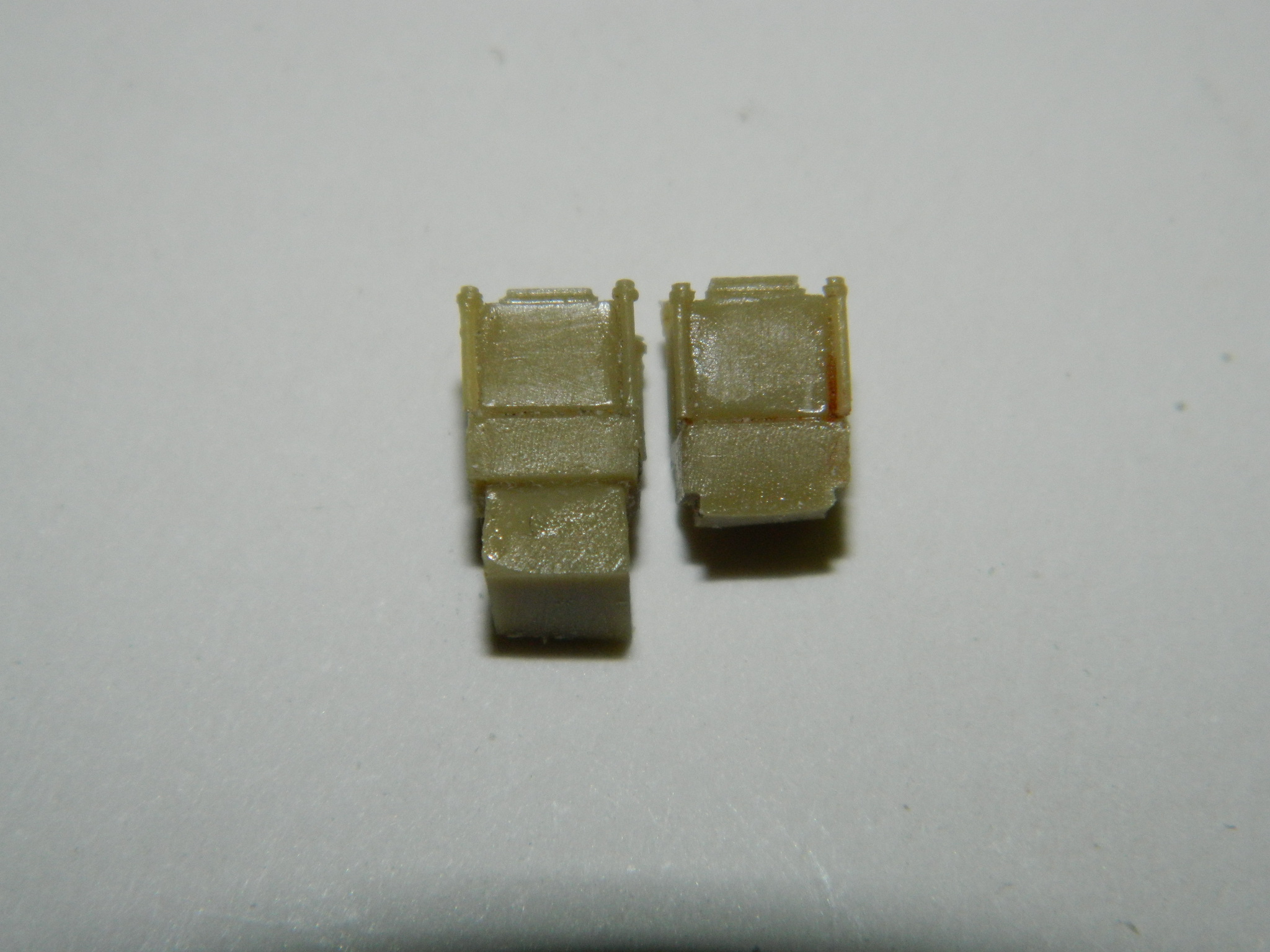
So I started assembling the engine. The first step is separating the parts from the pouring blocks:

When dry-fitting pieces together, I saw that the starter motor didn’t quite reach the bell housing, so I added a piece of sprue from my bits-box using superglue:

While the glue was setting, I saw/filed/sanded the exhaust manifolds free:

Then I attached the modified sump (the added piece, dark-colored on the lower right, will get trimmed later):
Dry fitting showed me that I’d trimmed one carb too closely so I had to add resin back (the tweezers are sitting on a lazy susan which makes aligning and gluing so much easier):


Fitted and trimmed the added plastic to discover that it doesn’t line up as it should. Short of remaking the entire starter, I realized that few would even see it much less realize it was “off” so I left it and glued the bell housing/clutch on:
Then I saw that the water pump had a major part of the cooling system that did not actually reach the engine, so I took some sprue, heated it over a candle, and once it was…well…plastic, I pulled gently trusting my Mk I Eyecrometer to get the diameter close (larger is easier to fix than smaller).
Good ol’ Mk I Eyecrometer nailed it on the first pull, so that was glued and set aside to cure:

Trimmed the added resin on the carb with a razor saw:


Then I added what looks like an air cleaner (it’s not, those are elsewhere in the engine bay, it’s actually a plenum chamber) and carbs to the engine as well as the modified water pump (later I had to snap the plenum off as I put it on backward, lest you think this is one unbroken chain from a pile of parts to Modeling Glory):

In looking at reference photos, there is a fuel pump on top of the engine that the AM set didn’t provide. In the above photo, the round thing under the plenum is the oil filler; the fuel pump is just as obvious, so I decided I’d need to build one. I spent a few minutes whining that I’d sold my Unimat lathe because it was SO much more precise than the lathe I have now…and then I realized something. This is plastic, not metal. I didn’t need a lathe; I needed something that I could clamp a piece of sprue into and spin slowly (otherwise the plastic melts). Enter the variable speed drill:


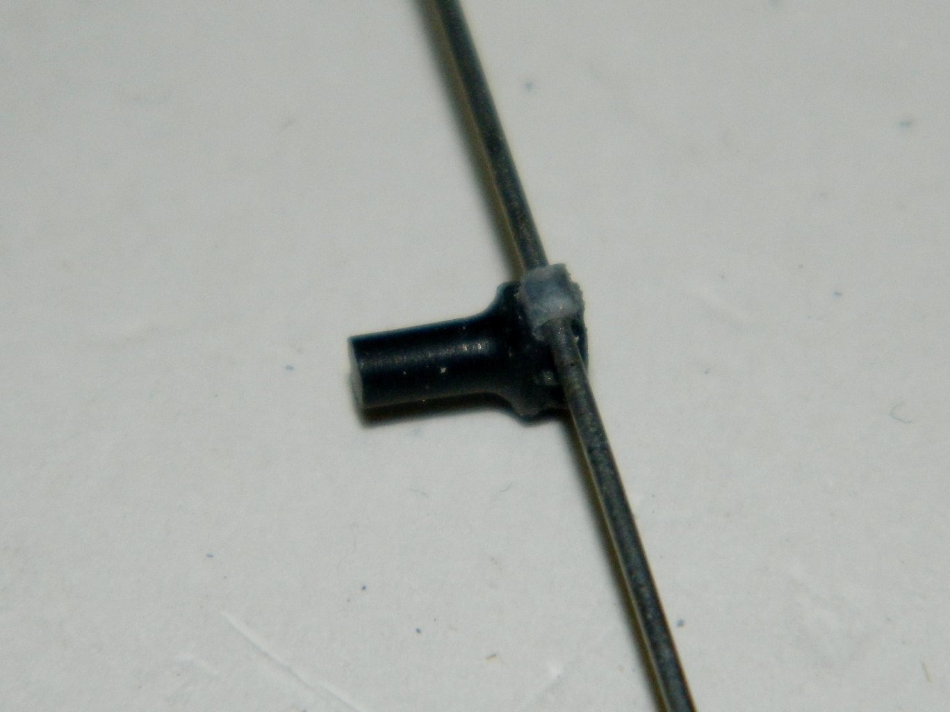
With the basic shape of the pump done, it was time to add the details. I added the shafts of the bolts using lead wool (just like steel wool only lead…how odd…available from plumbing supply and A LOT easier to work than copper…gah…or plastic…annoying). Then I glued a piece of plastic to the side where the fuel line from the pump goes to the carbs. I tried a couple of ways of adding the fuel line and it became quite evident that butt-gluing (don’t go there…like you just did) wouldn’t work (not enough surface area for a secure bond) so I drilled it out and will use a length of solder of .032 (8.13mm) diameter as the fuel line because it’s easy to bend, maintains that bend, and is structurally sound:

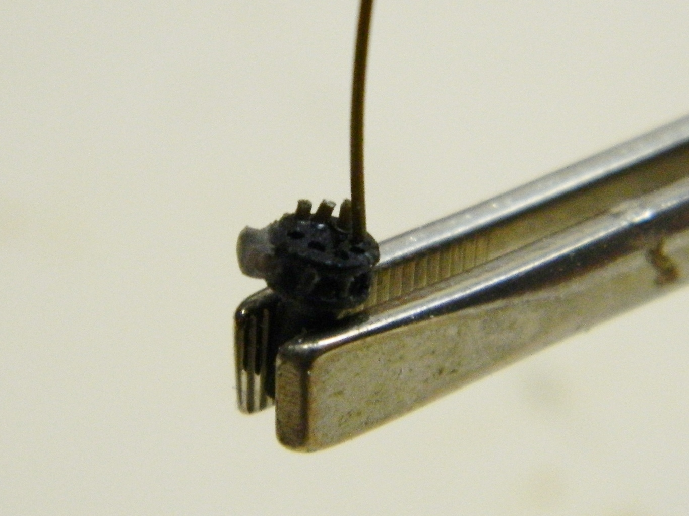
To replicate the bolts on top, I drilled the locating holes slightly, shaved sprue into an octagonal form (like the bolt heads I’m trying to replicate), and used the tweezers on stands to align and glue. I’ll trim them to size later (later on I would use Grandt Line styrene bolts for something like this but at the time I didn’t have them):
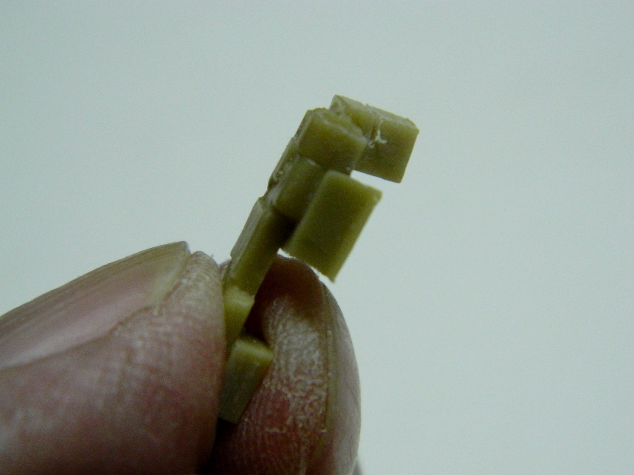
I wanted to add the magneto assembly next. I discovered that the back half of them weren’t modeled and since they would be easily seen needed to be. I used some of the cut off pouring stubs so make things easier to see:

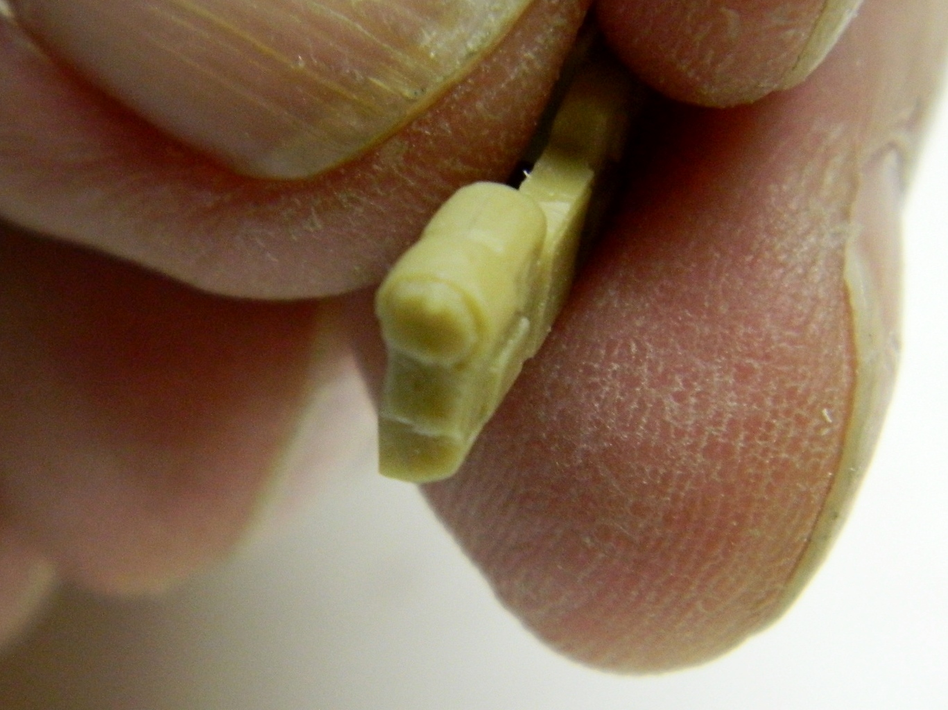
Since that worked well, I did the other side the same way.
