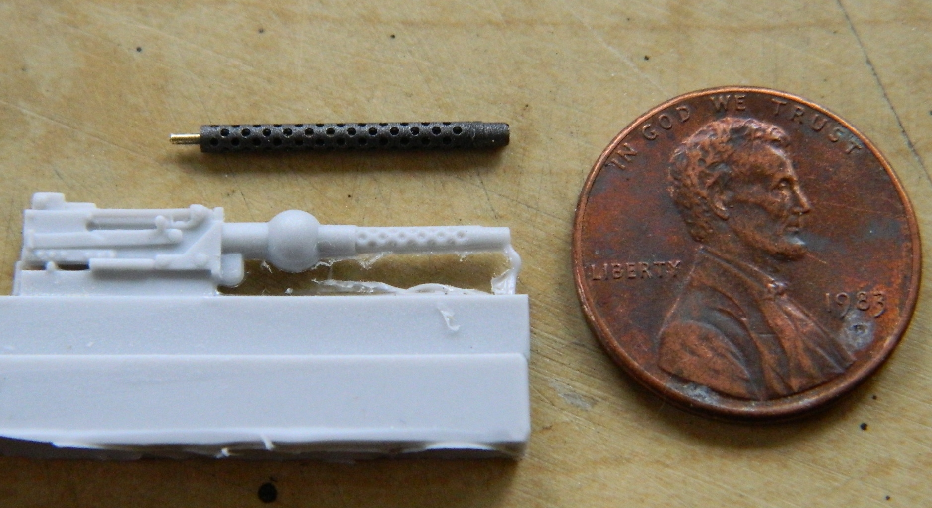
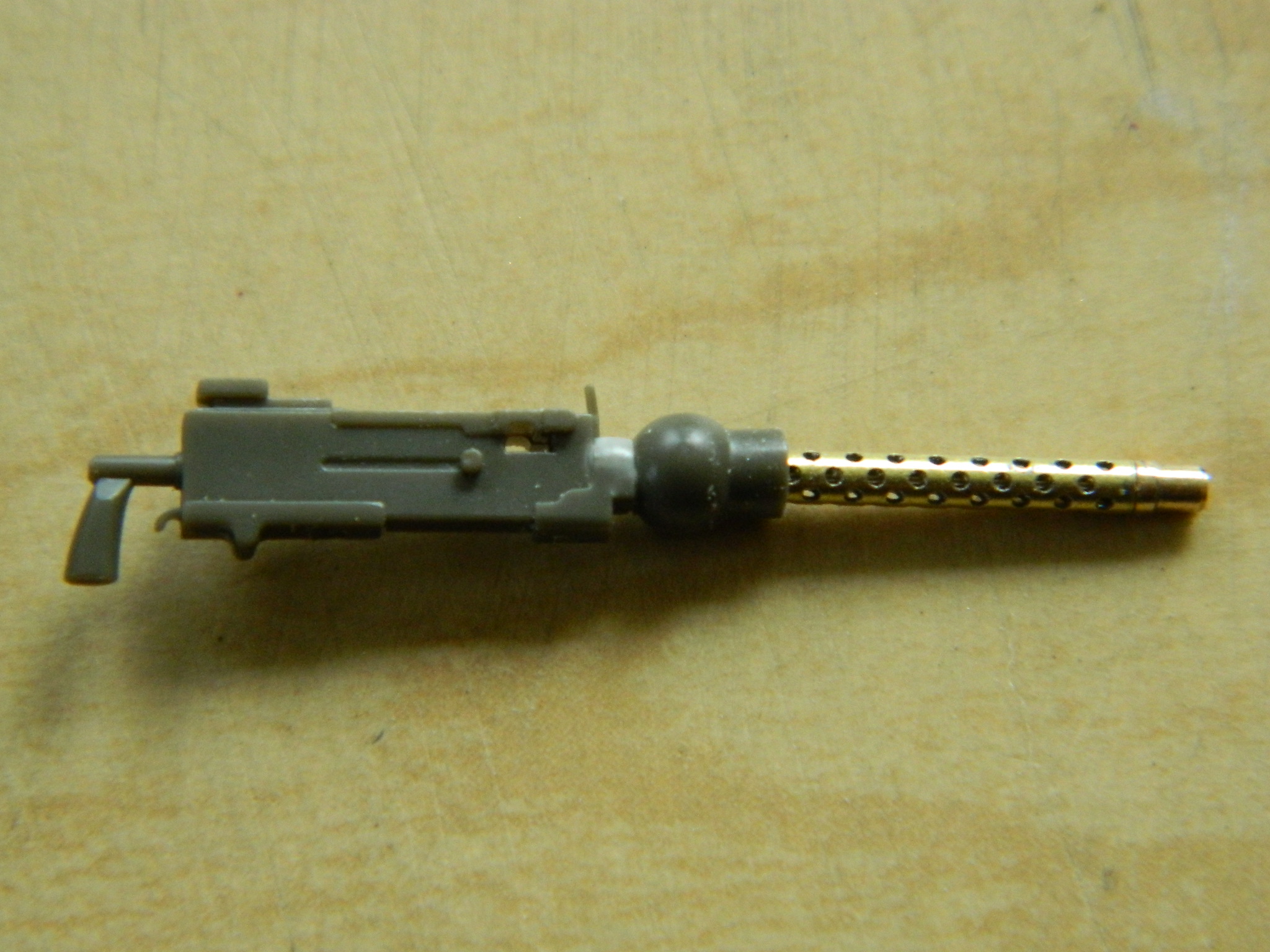
Going back to working on the upper hull interior, it was time to start working on the .30 caliber (7.62mm) machine gun in the bow. I found exquisitely machined brass machine gun barrels for both the .30 (7.62mm) and .50 (1.27mm) caliber machine guns (M&Models). I painted them prior to assembly:


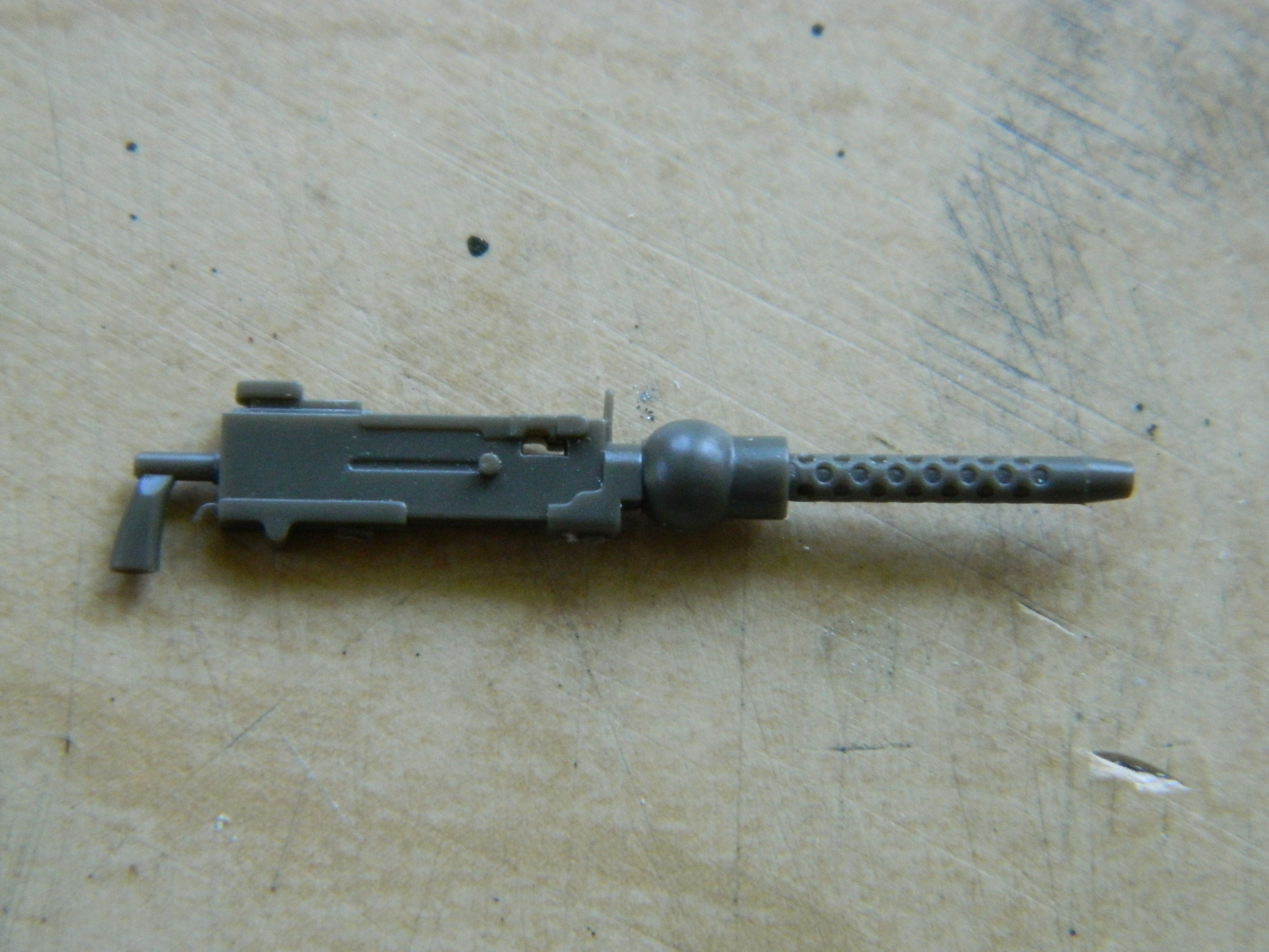
I’m going to replace the bow gun. That means the barrel and jacket get assembled:
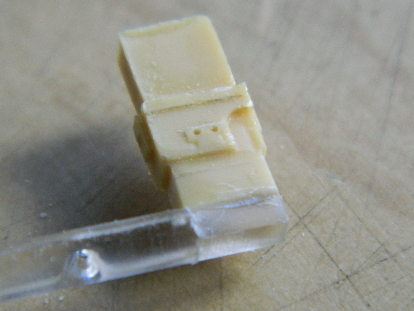
Next step is to cut off the resin barrel and drill a hole for the new barrel to seat into the receiver:

And that was another mistake. I didn’t check the overall length of the assembled gun and the barrel extends much further out than it should (much like my stomach does):
Since it’s superglued into the receiver, and since acetone softens superglue, I dropped the assembled gun/barrel into a jar of it and let it sit overnight. The next day I discovered a couple of things. First, the acetone did indeed loosen the superglue and the barrel/shroud slid right out:
What the above photo doesn’t show is that the receiver is no longer solid. It’s rubbery. Like thin rubber. Well, bugger…
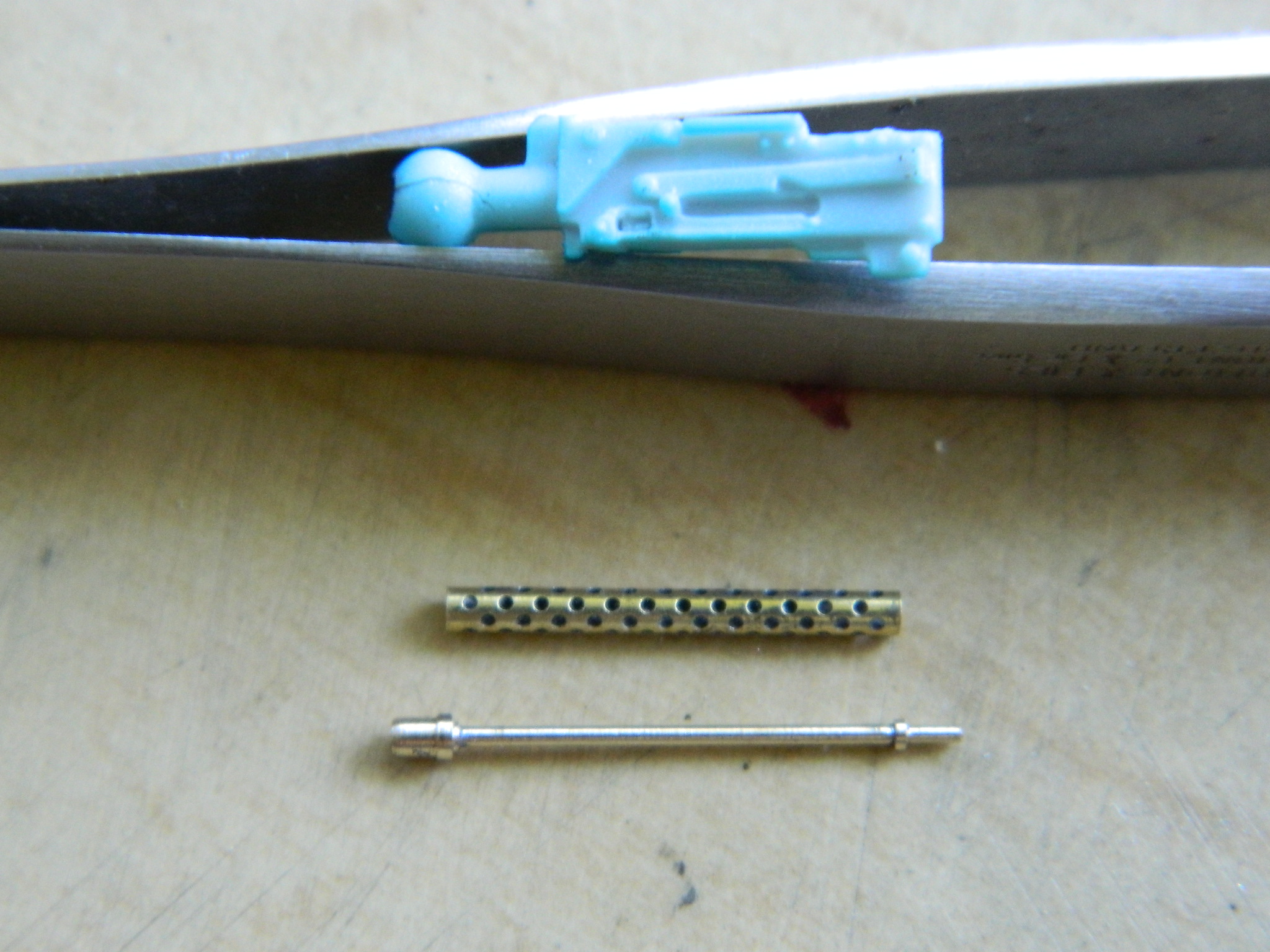
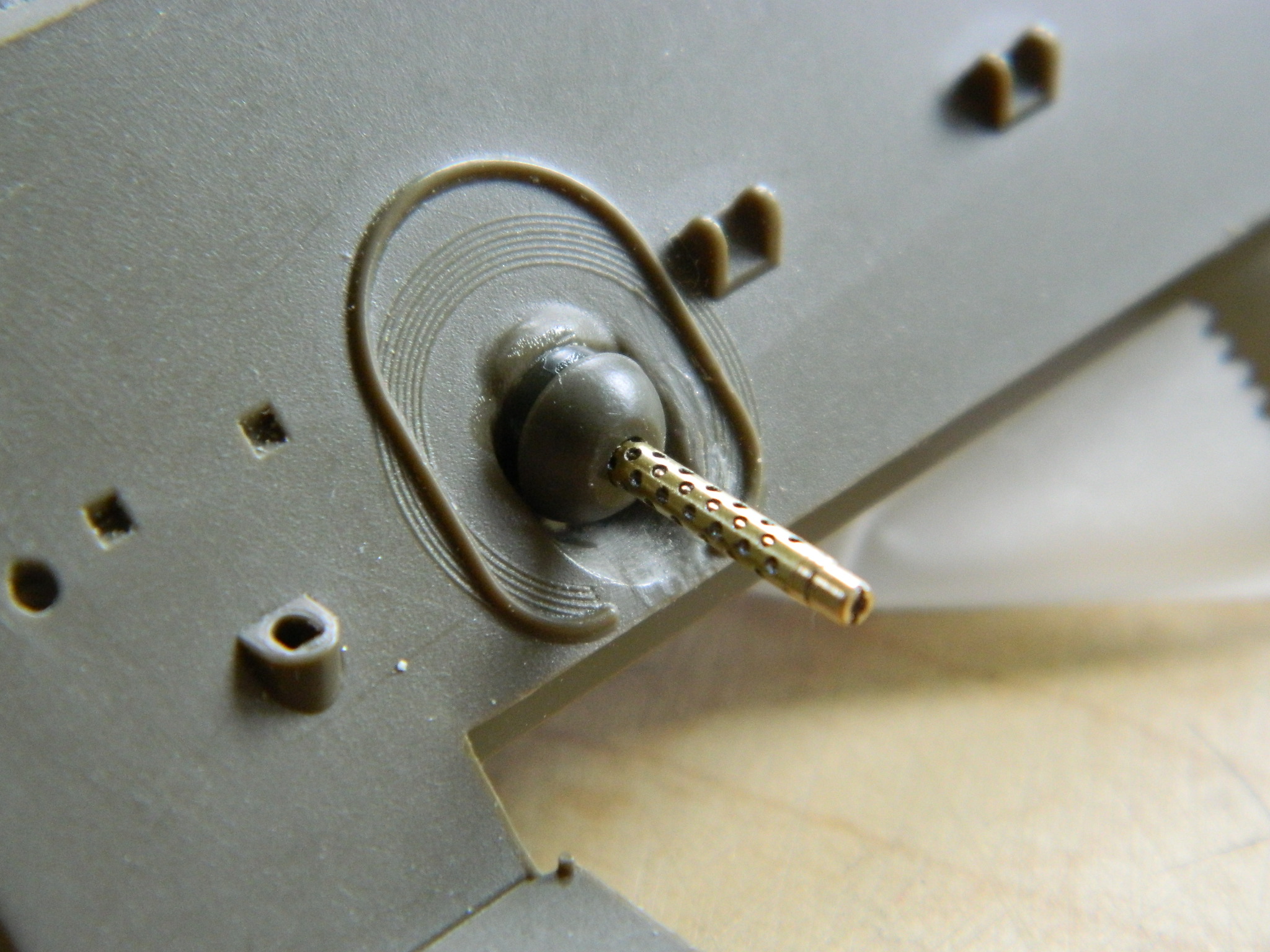
I rattled around in my spares boxes and found the bow gun from an Asuka kit (or Tasca, as they’re calling themselves now):
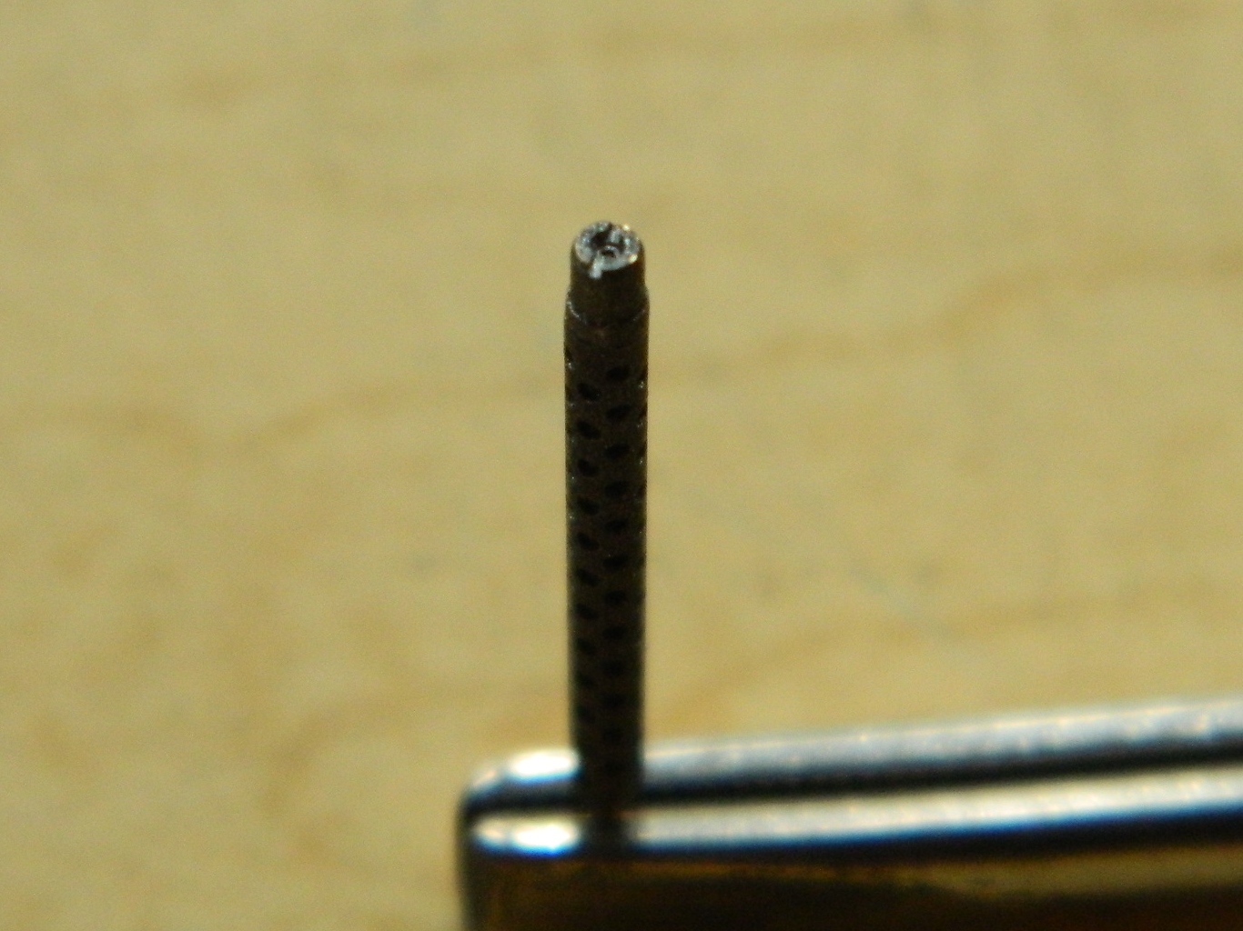
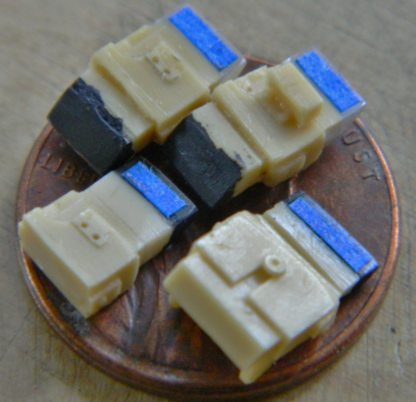
And this time I certainly drilled it deep enough. If you click on the picture below and zoom in on it, you’ll see that just in front of the shell port where the bit has deformed the plastic outward (but given where this gun will reside, that won’t ever be evident):
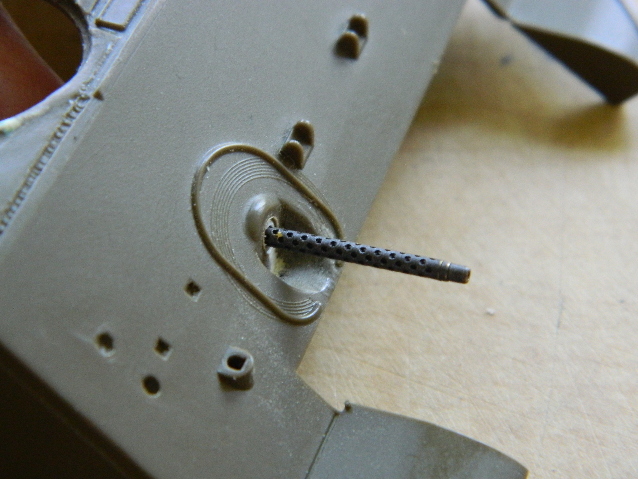
And now (unlike my stomach) the barrel doesn’t stick out too far:
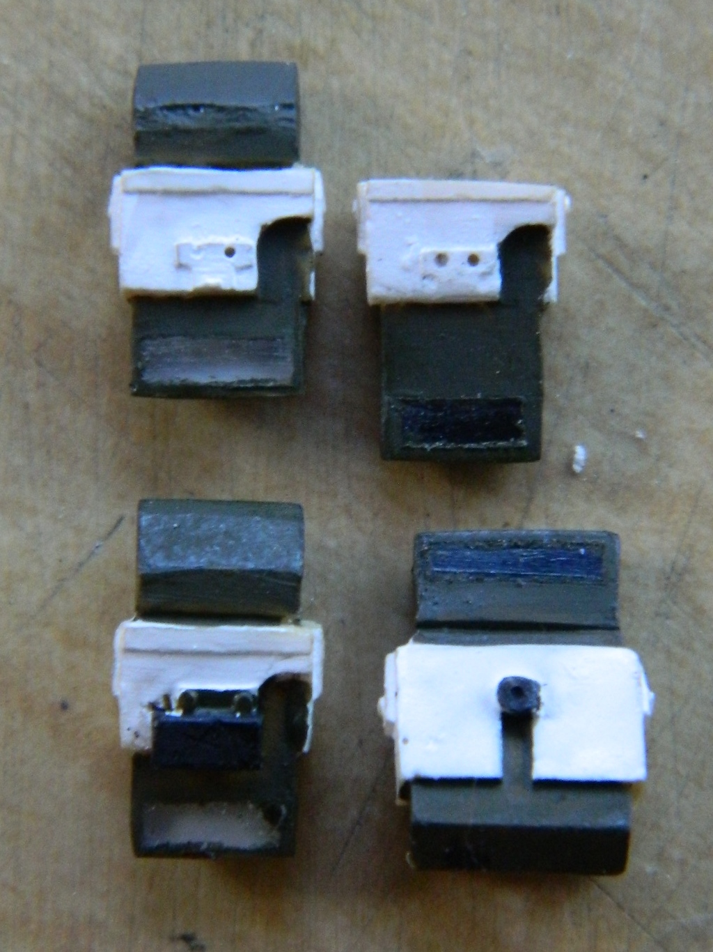
And since I’m replacing the periscopes and their flip-up covers, I had to remove the molded on cover and replace it with a resin cover of a size matching the cover of the driver’s periscope (after filing the head out from under it):
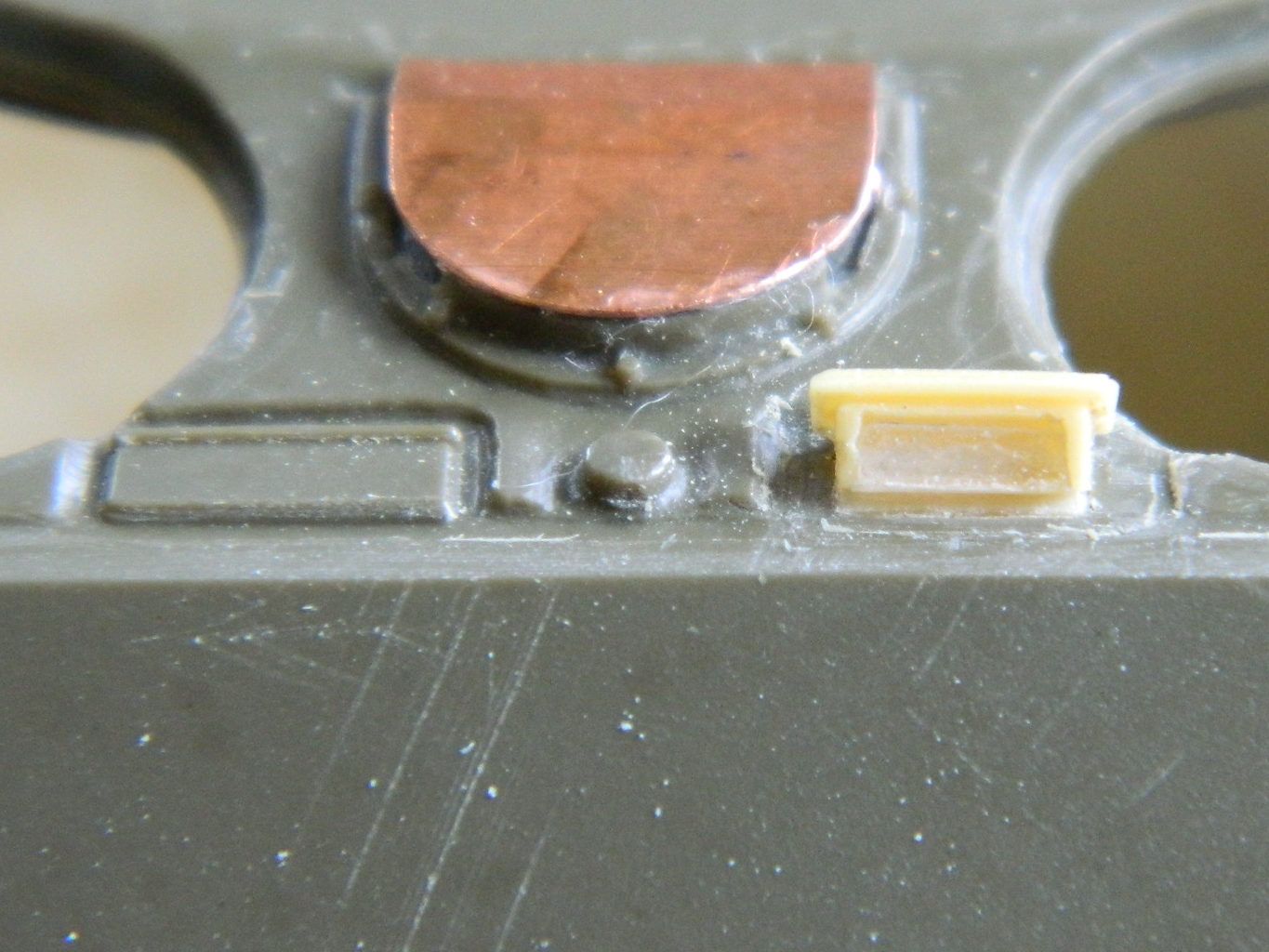

Since I realized that the vent blower is going to get in the way of the periscopes, the bow gunner’s periscope will be modeled retracted. The problem with that is that all the resin periscopes are molded open. That means I have to extend the bottom of the periscope and add clear sprue to the bottom where the view-port is (and I had to add a little putty):


Since I was revisiting the periscopes, it seemed a good time to get some paint on them. I back painted the clear heads; internal heads that look out get back painted a light color, the external heads that look in get painted a dark color, and then they were masked off while they were still easy to get at:
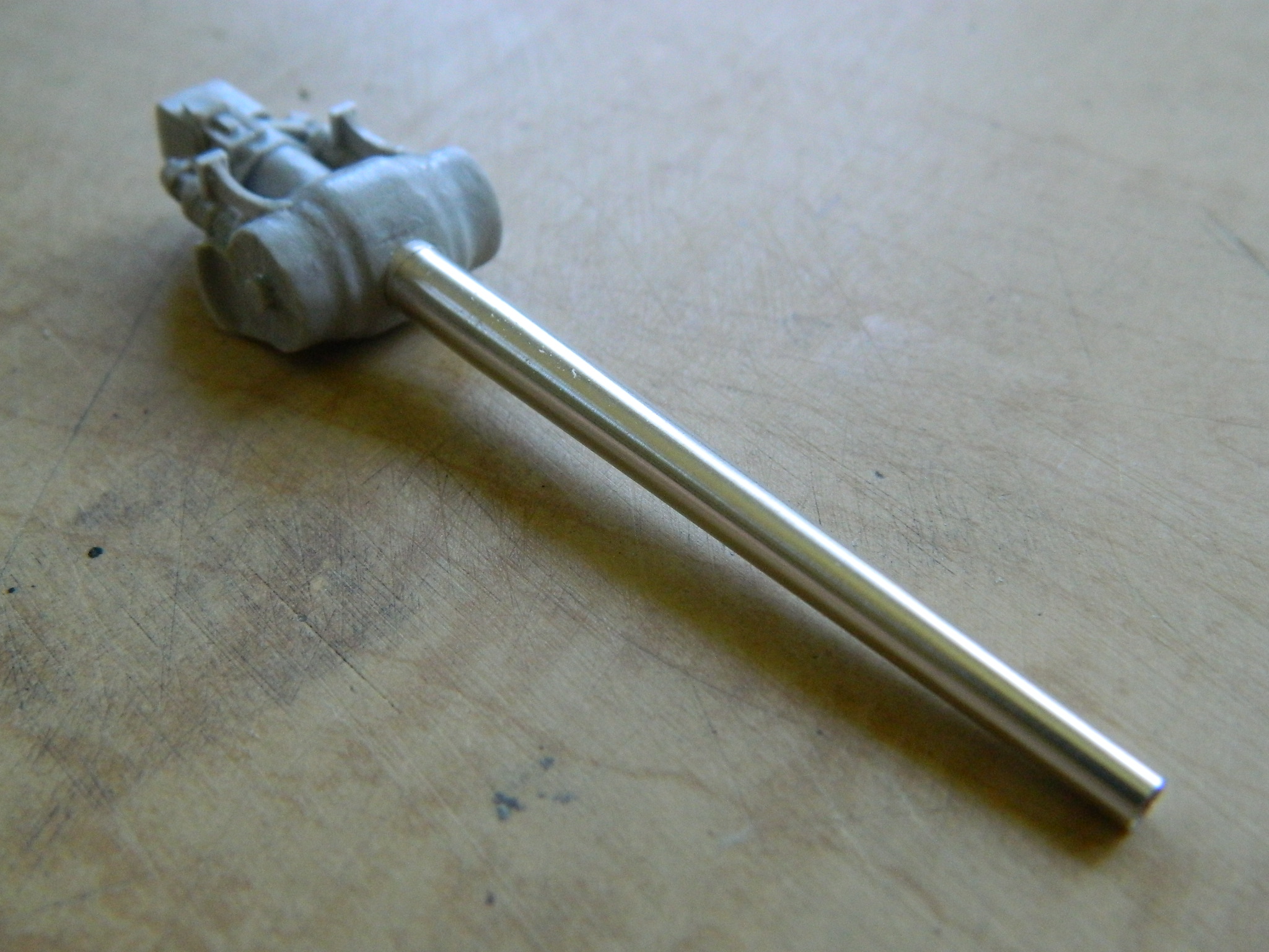
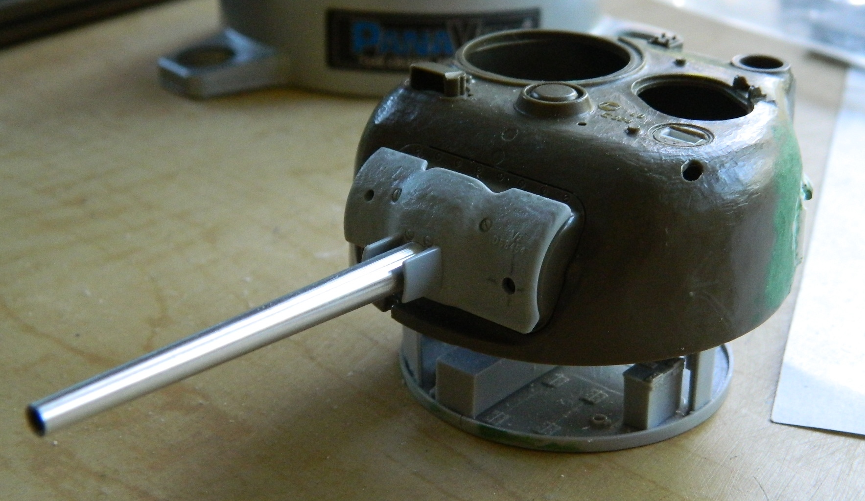
Getting back to the turret for a while, I started work on the main gun (75mm) assembly. I picked up a really nice turned aluminum barrel that even has rifling in it (M&Models again)! Step one was to drill out the mount and socket the barrel into it:

What I found interesting is that the hole is so snug that the air behind it pressurized. The barrel came out (easily, in spite of superglue) so I drilled a relief hole under the gun mount to give the air someplace else to go and glued the barrel back in more securely.
Totally unsurprising at this point, there are fit problems. After doing some skull-sweat, I realized I would not be able to use the cast-on resin pivot (fit and structural considerations). As so happened, I just happened to have copper tubing of the correct diameter. I drilled…carefully…in from both sides of the gun mount towards the center and dayum if I wasn’t within .005″ (.127mm) of being spot on:

Given that fit problems abound, it was time to dry-fit this next step and see how things were fitting (or not):

Things were fitting, mostly, but just like in an actual Sherman, “space” is only found outside.
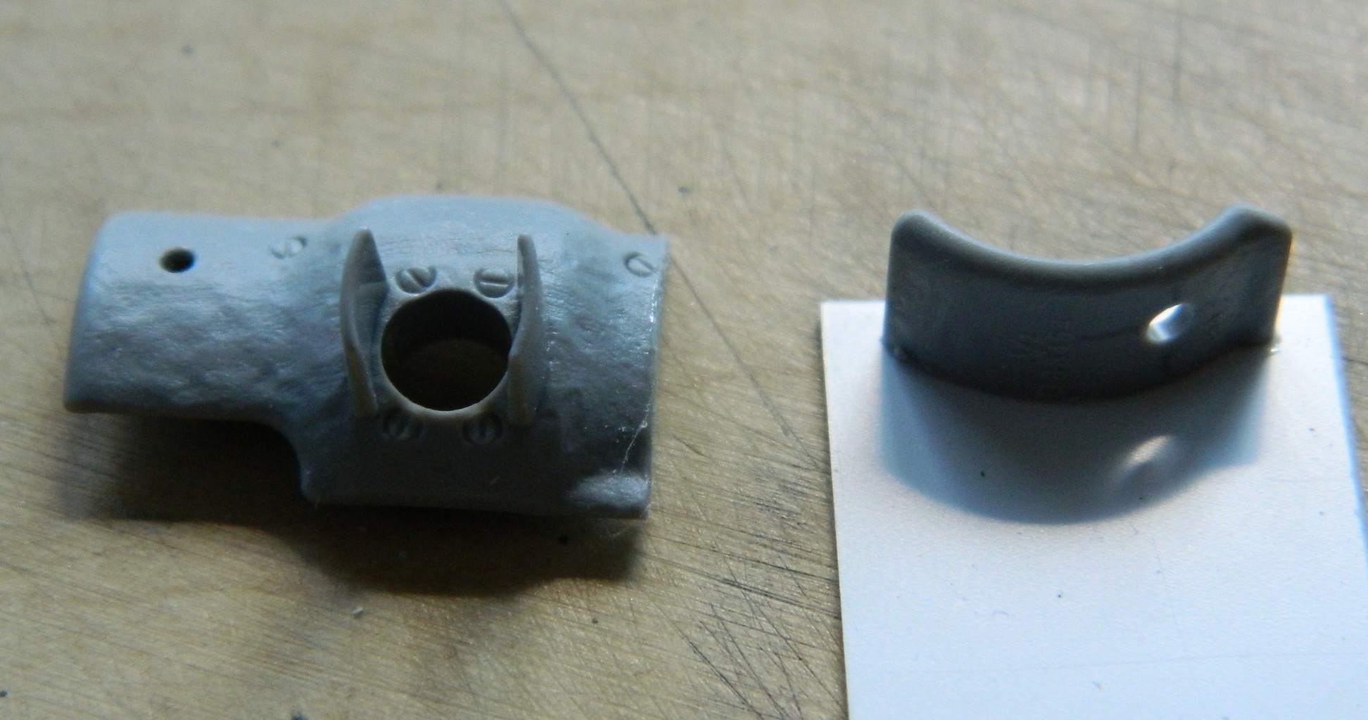
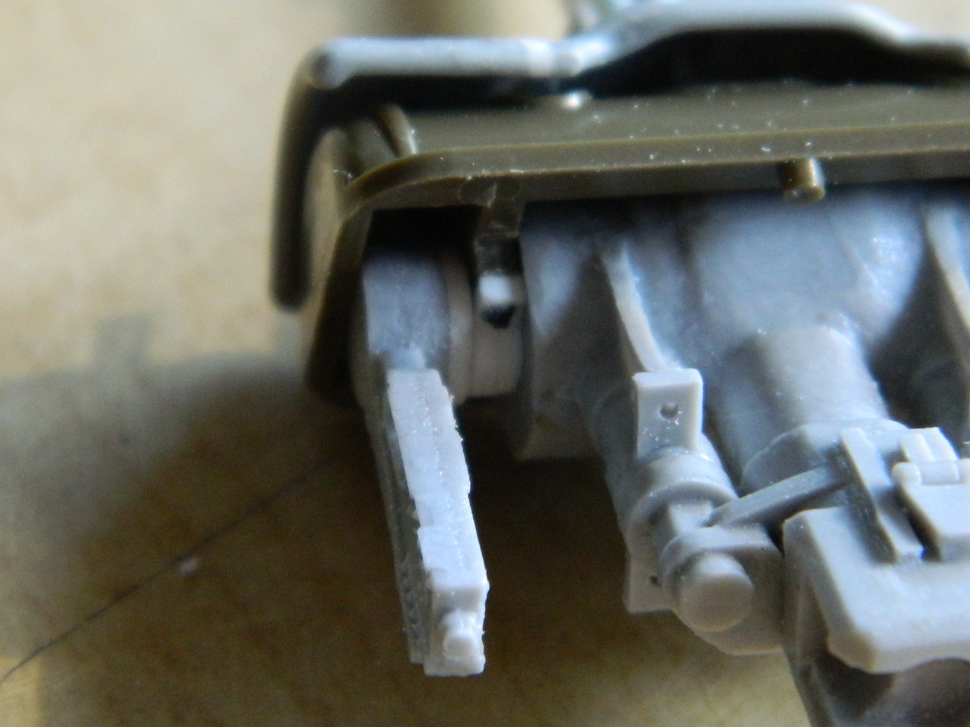
So it turns out there are fit problems. The mantlet I want to use is from a different kit (Dragon, because it has better surface detail) and does not quite line up with the gun shield behind it and that’s going to mean neither the coaxial .30 caliber (7.62mm) machine gun nor the gun sight will line up properly, as they have to go through the shield and mantlet:


That means I have to widen the mantlet. It’s still not EXACTLY there, but I can work with this by widening the slots in the gun shield to pass the .30 caliber (7.62mm) and gunsight through:

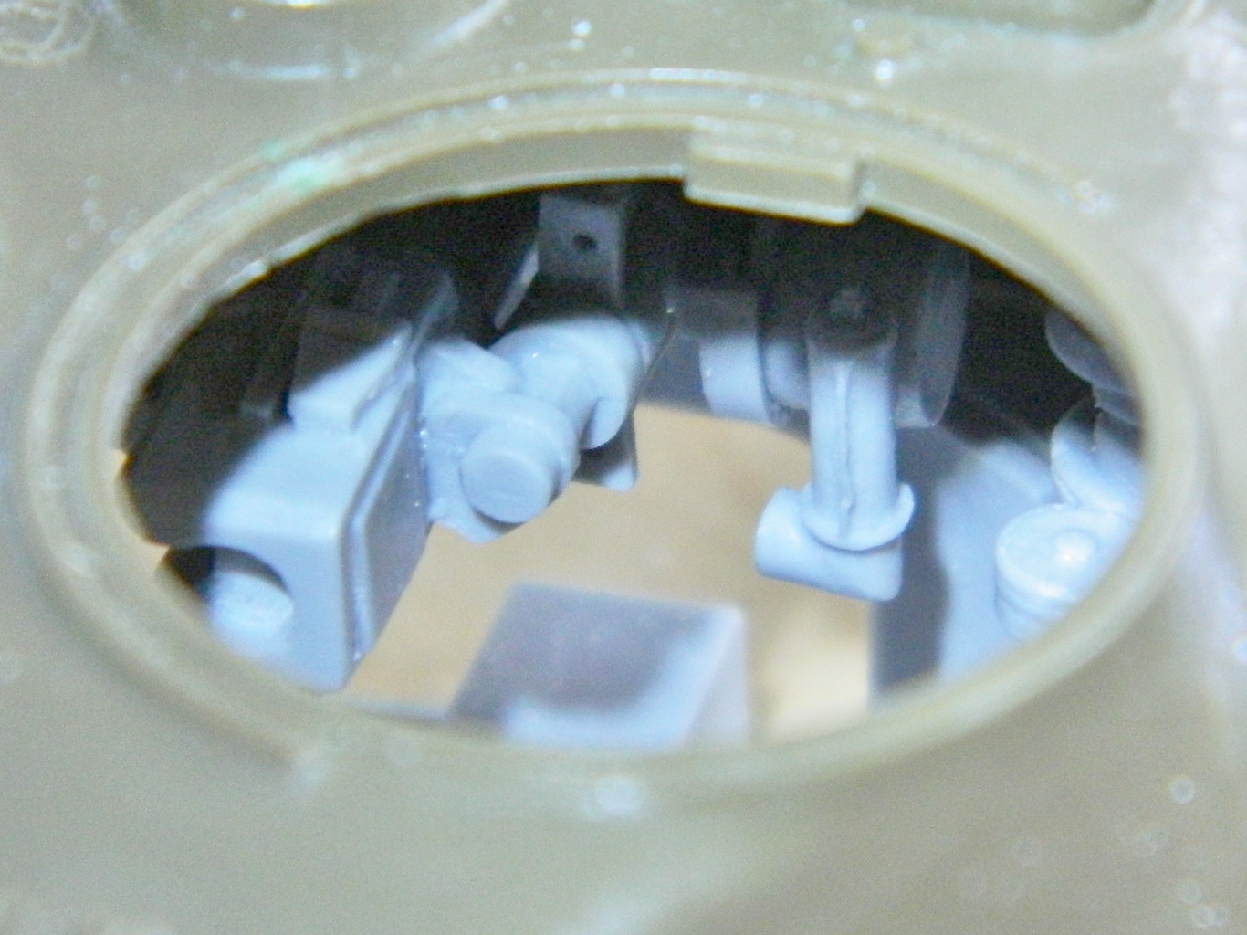
To give you an idea of what modifications are really being done, this is what the kit provided for this whole section:
Yeah, the kit parts all line up, but if the hatches in the turret are open…and they’re going to be…there ain’t jack to see in there.
Next step is the trunnion caps that hold the gun assembly to its mount. To do that, the molded on mounts have to be filed to about half their original length and caps fitted to the stubs:
After I shaped the trunnions and added bolts, the fit is checked again:
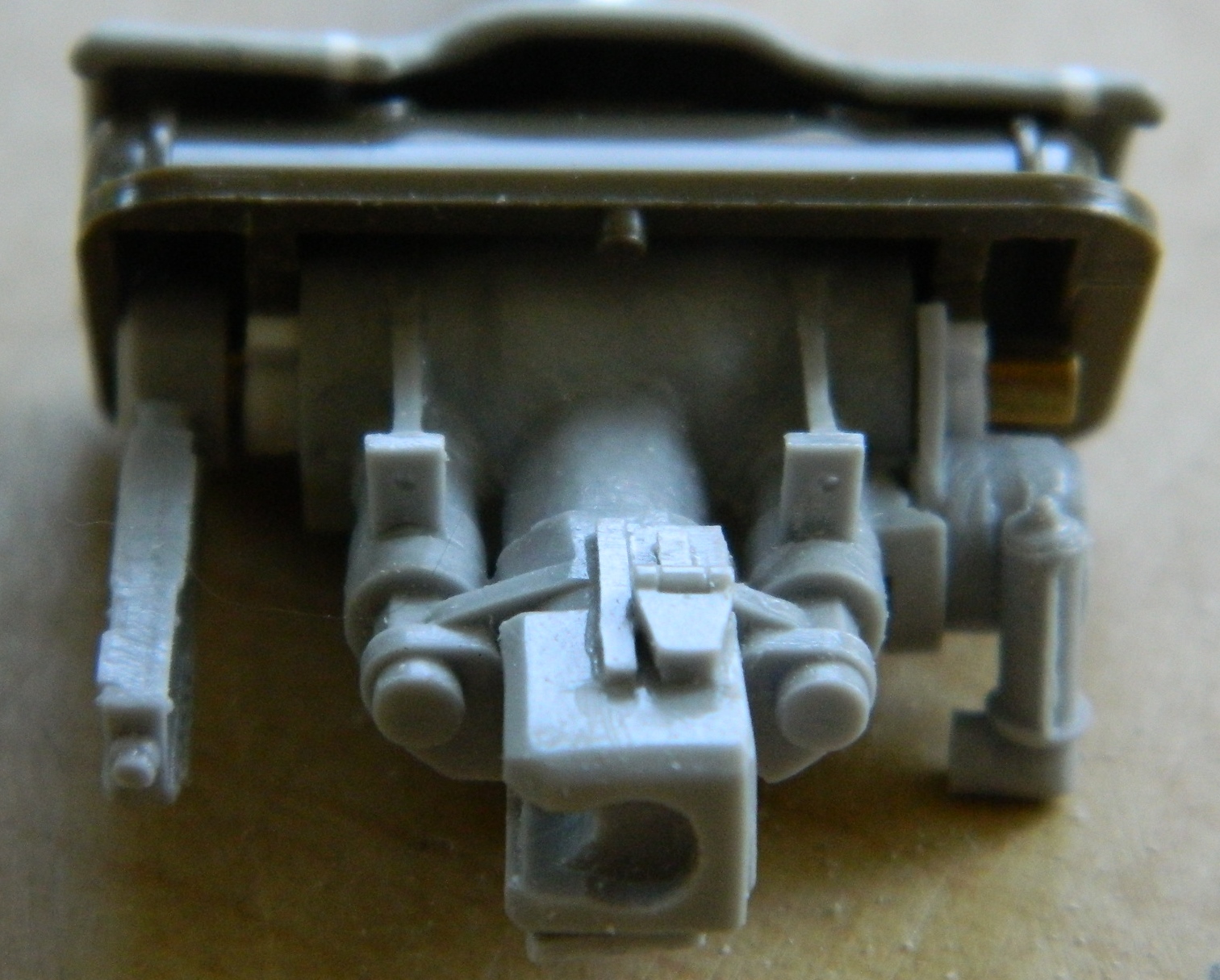
And yes…there are problems. There’s a gap between the .30 caliber (7.62mm) mount (on the left of the above photo) and the rest of everything. Time to fix it. If you look closely, just to the inside of the .30 cal (7.62mm) is a disc of plastic that takes up that now occupies that space:
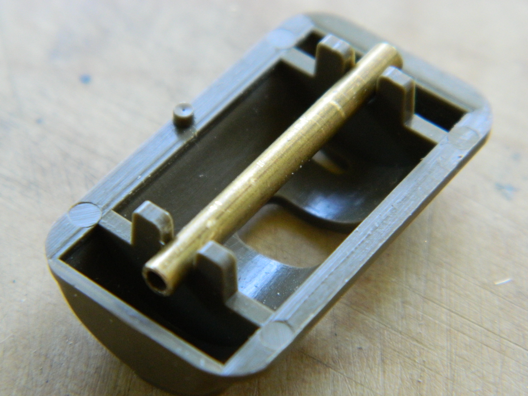
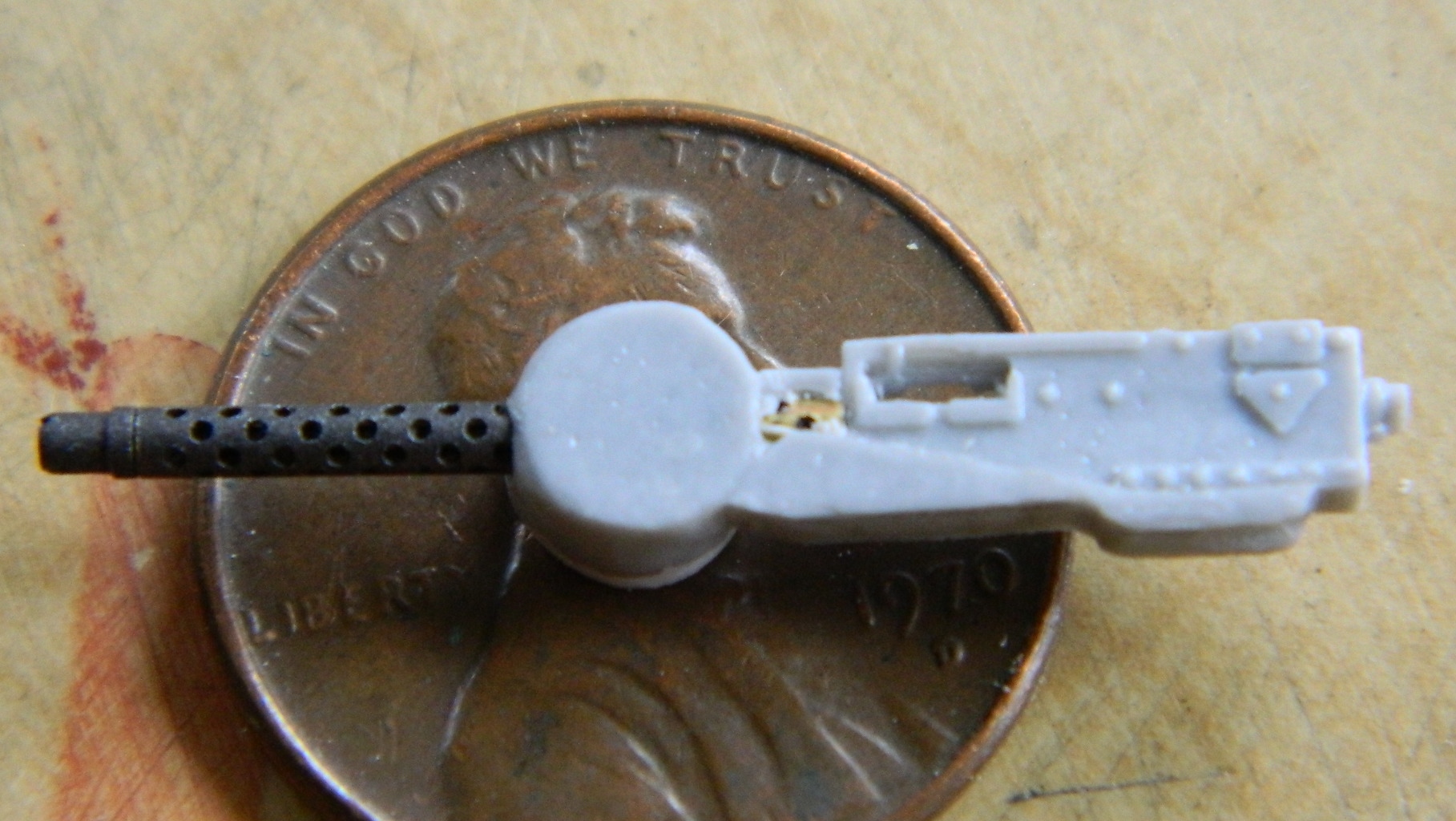
And then I cut off the resin barrel and added the really nice two-piece brass set, only THIS time I made sure I’d drilled the part out far enough. All of this drilling I’m doing is done by eye and this particular piece was nice confirmation that my old eyes still work pretty good. I got this thing centered within minuscule variation as evidenced by the barrel protruding equally on both sides of the body of the gun (which won’t be seen after it’s installed, especially once it’s been painted):

The Sherman’s turret was rotated electro-hydraulically, but there was also a manual crank in case the hydraulics failed (or were shot out). The AM part didn’t provide the handle so I have to add that:

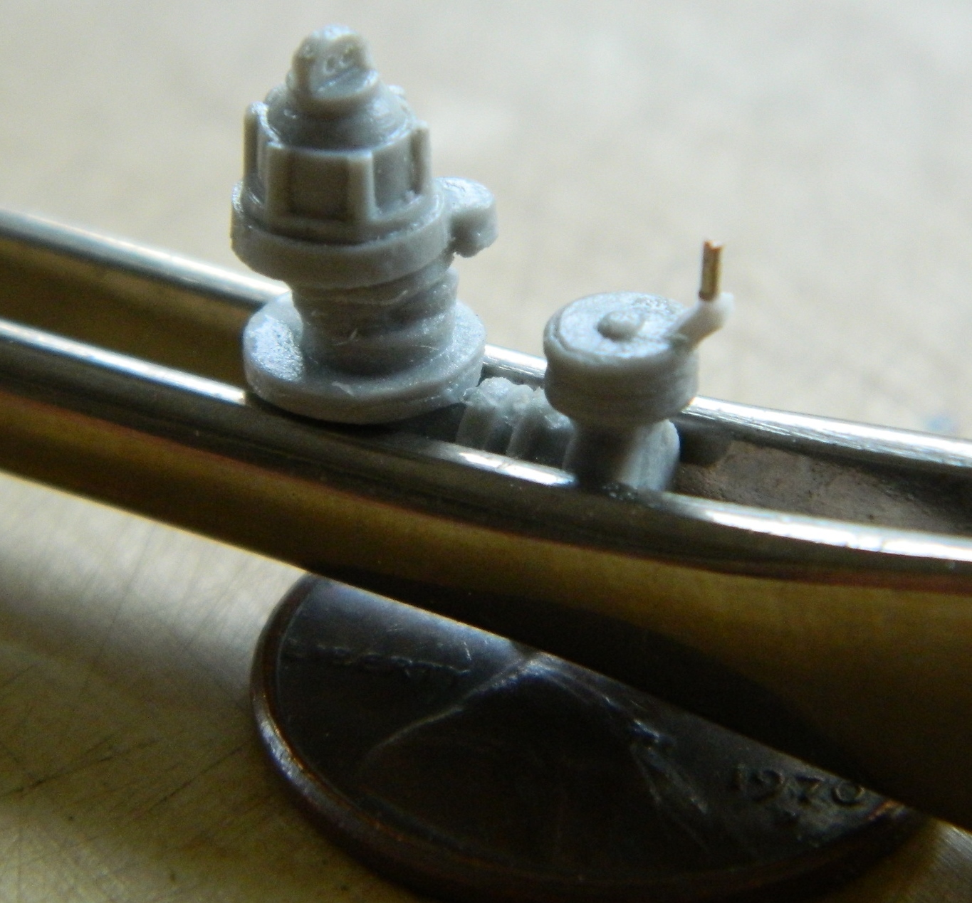
Then while checking my references about something else, I noticed that I put the gun sight assembly in at the wrong angle, so that had to come out and be reworked. The part that’s off is the piece below the sight which is the elevation control. The picture shows the angle that control is supposed to be mounted at and the angle of the sight tube shows how far off I managed to make it:
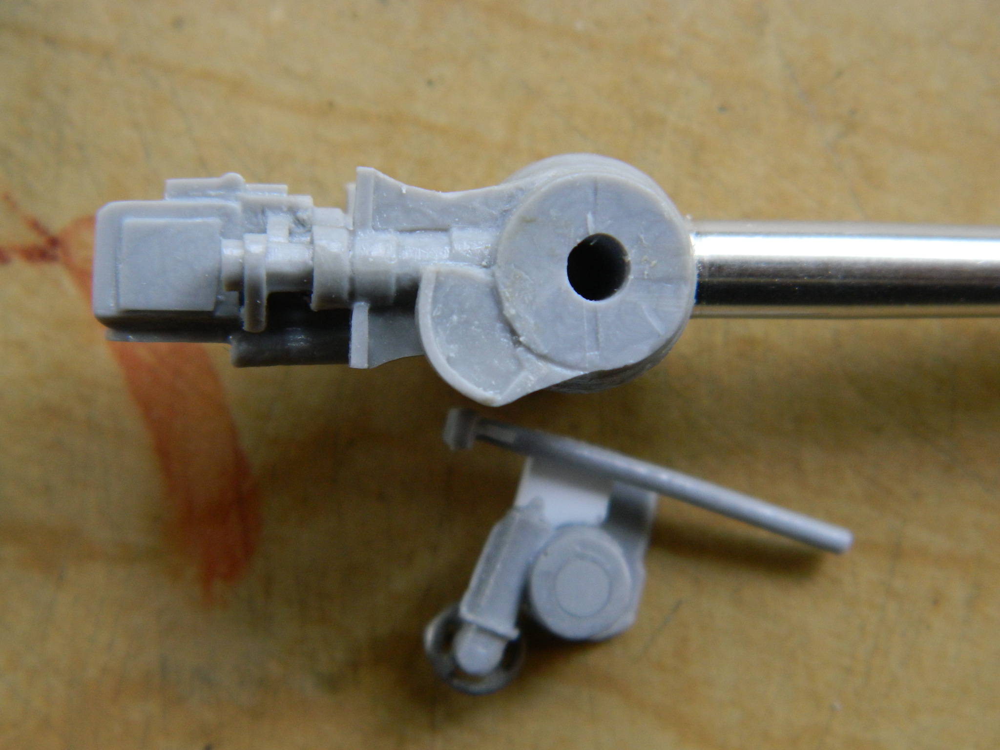
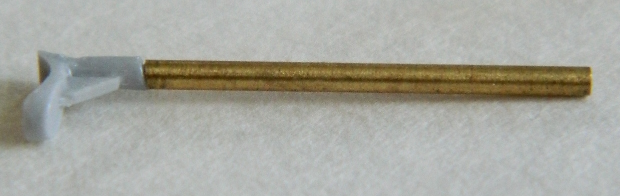
Due to the fragile nature of the resin and the very small diameter of the sight, I thought I would surely snap that bastid off…which I did not. However, while I was working the piece loose (sharp knives are OUR FRIENDS) and considering what options I might have when I did snap the resin sight off, I came up with another method of making the sight that I liked a lot better. All I needed was copper tubing of the correct diameter…and it turns out I have that on hand:
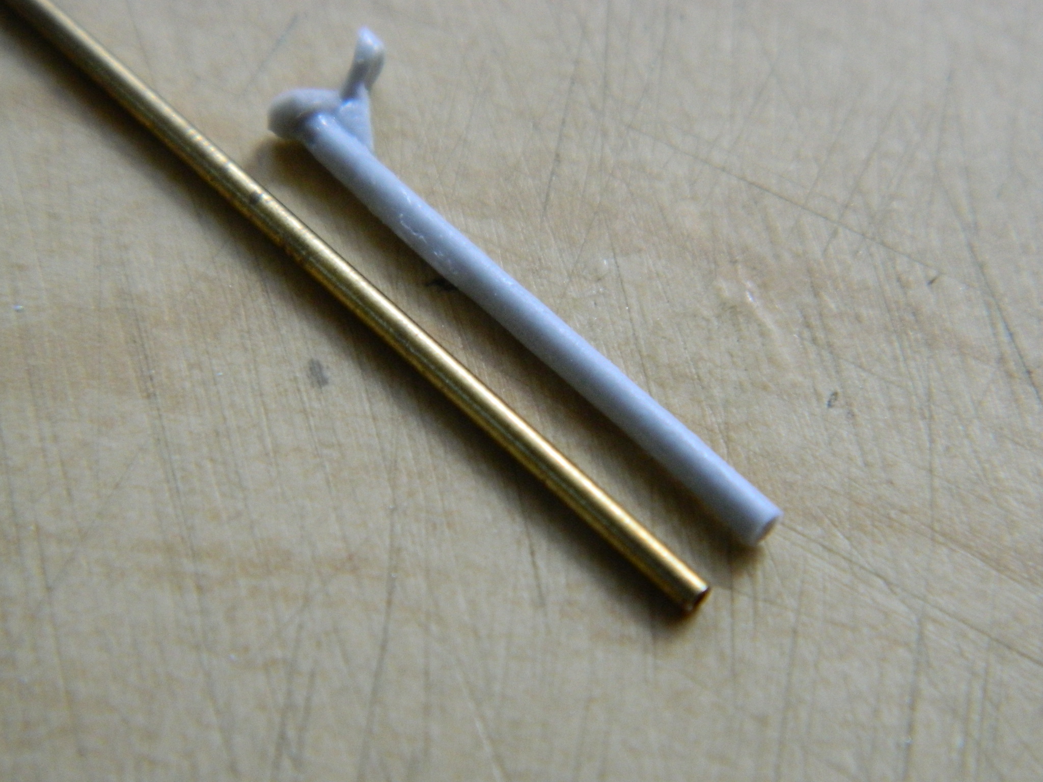
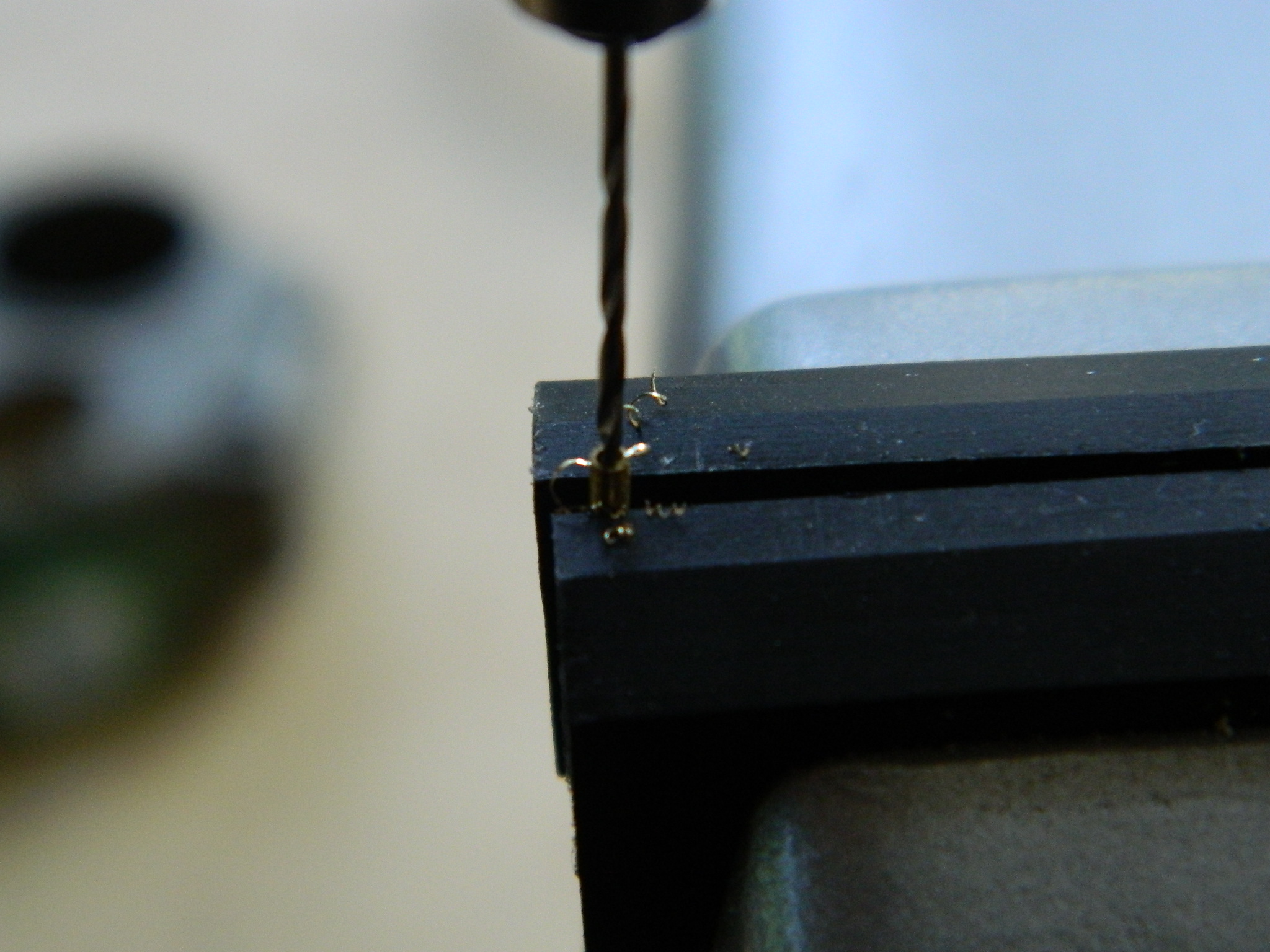
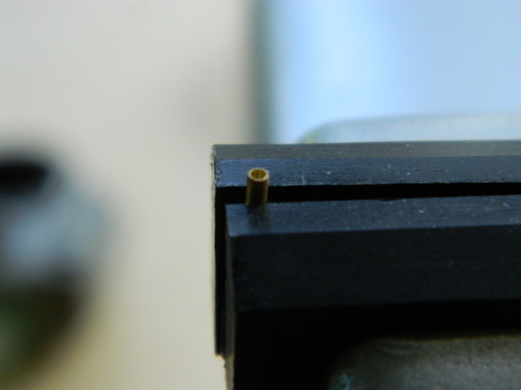
The first step in using it was to drill out the end of it (by hand!) so that it doesn’t appear to be out of scale:
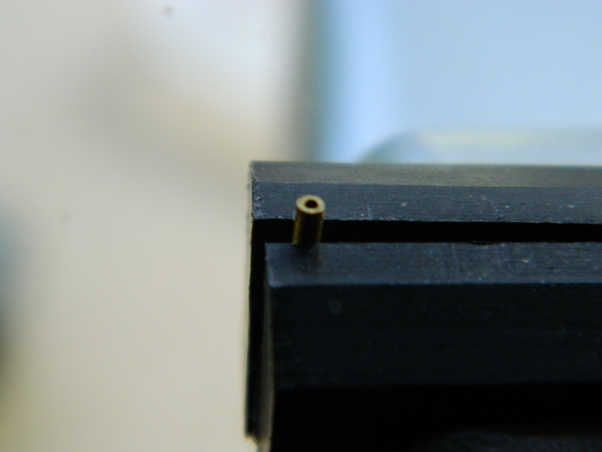
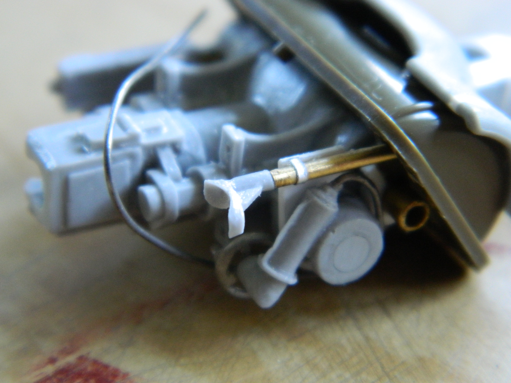
In order to mount it securely to the eyepiece, I drilled out the resin and glued a wire on, then I slid the tube over the wire and glued it securely in place:

With that taken care of, the elevation/sight assembly got glued back to the gun and its fit with the mantlet checked and I like this a lot better (I also added a mounting bracket – aluminum foil – and the control cable – solder – to the elevation crank housing):

I just wish I’d noticed at this point that the eyepiece on the site was incorrect. The way it’s set up in the above photos, the gunner would use his left eye to lay the gun on target, but in reality it was set up for him to use his right eye. But I didn’t notice…
The ratchet-release for the manual turret traverse (aluminum foil again) got drilled, trimmed, and glued on (and then shortly thereafter the fragile handle snapped off; that will get added on later once I no longer have to manipulate that part):

