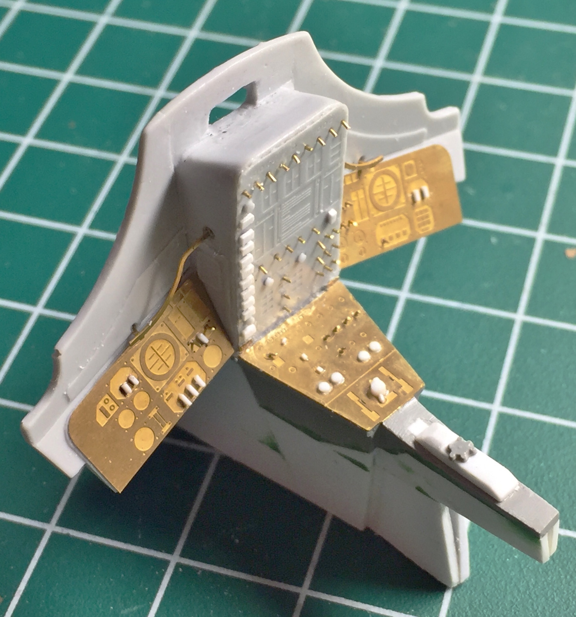
With the control and instrument panels detailed, it was time to fit them. Checking references, I see that the sides of the center console doesn’t float unattached the way the kit parts do; they go all the way to the floor:

So using .040″ (1.016mm) sheet, I started extending the sides of the console:


Dry-fitting showed me there’s still a way to go with this:

I still have to add more to the sides of the console, but lacking four (or more) hands, I needed to reduce the number of individual parts (and tape) for dry-fitting so I attached the console to the main panel. Normally I use superglue to attach resin bits to each other. Due to such a small contact area between the console and the panel, this time I used 5-minute cure epoxy:
There is a joystick on the center console which will also need to be replaced. I started with five pieces of .020″ (.205mm) sheet (scraps, actually), drew the outline of what I wanted on the spine of what will become a more accurate joystick, and started dimensioning and gluing the other four pieces into place:
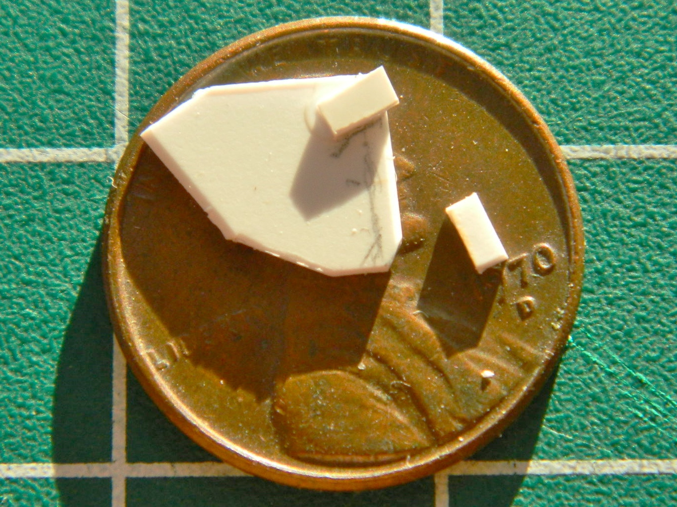
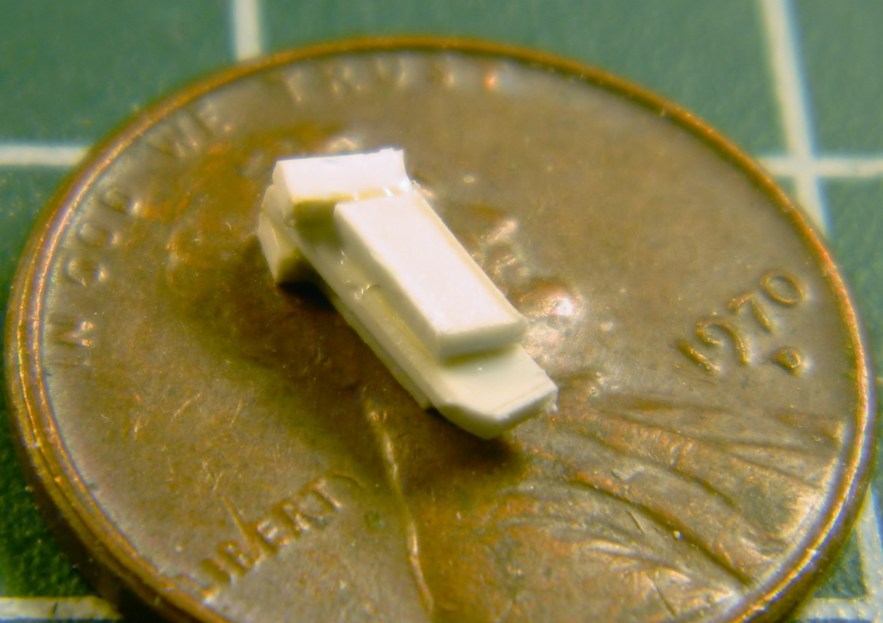
Then there were MANY DAYS of holding the sodding TINY part between increasingly sore finger tips while I scraped, filed, sanded, muttered, CURSED…er…exercised my ability with colorful (and anatomically unlikely) invective, interspersed with A LOT of time crawling around the (filthy, as it turns out) floor with a flashlight trying find out where the [INVECTIVE DELETED] thing landed this time after I dropped it. Finally I ended up with this:

When I spend so much time on something that is so small, I wonder if I’m actually in a small room somewhere, rocking back and forth and whimpering. Anyway, the joystick is mostly done with only a few very minor tweaks (as if the joystick itself isn’t minor) left to do to it.
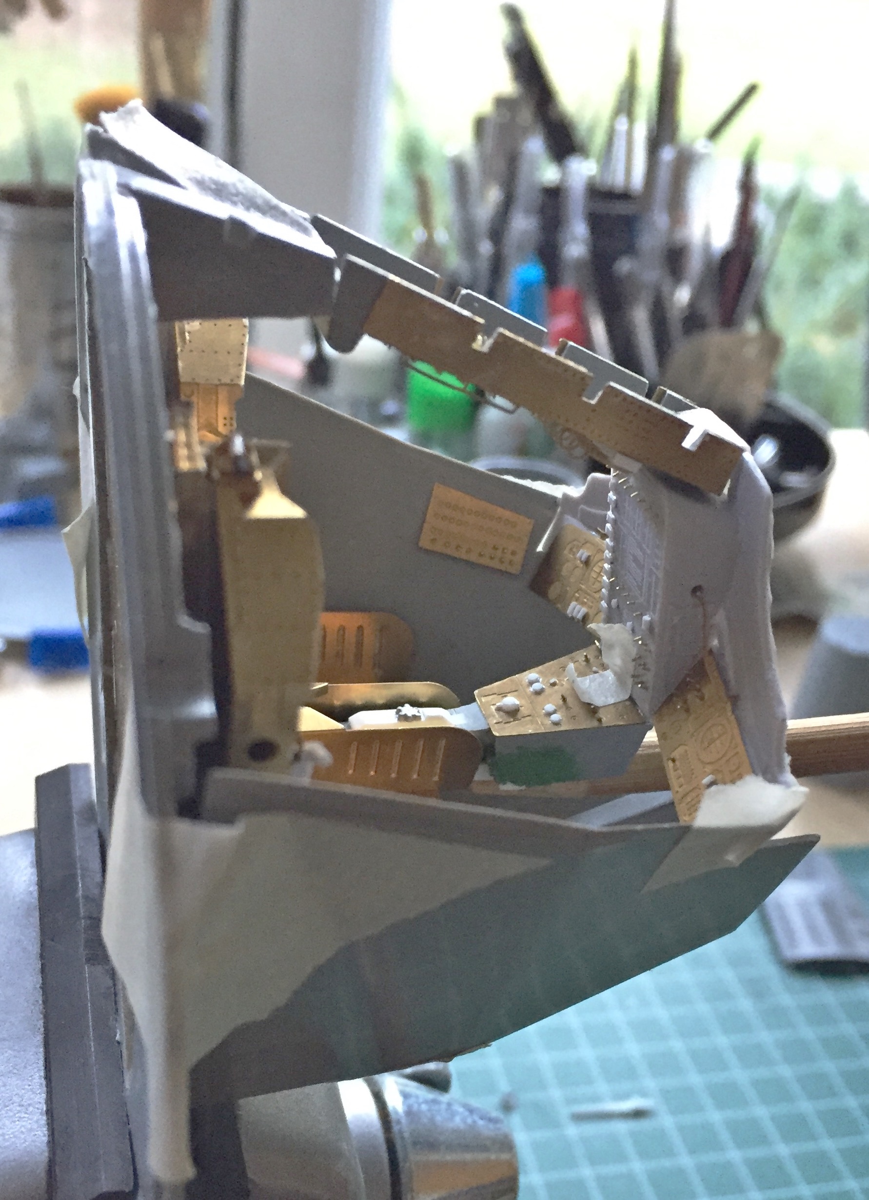
One of the things I’ve found I have to deal with when building is the “before you can do this, you have to do that first, otherwise you won’t know how things fit.” With the console I’ve reached that point.
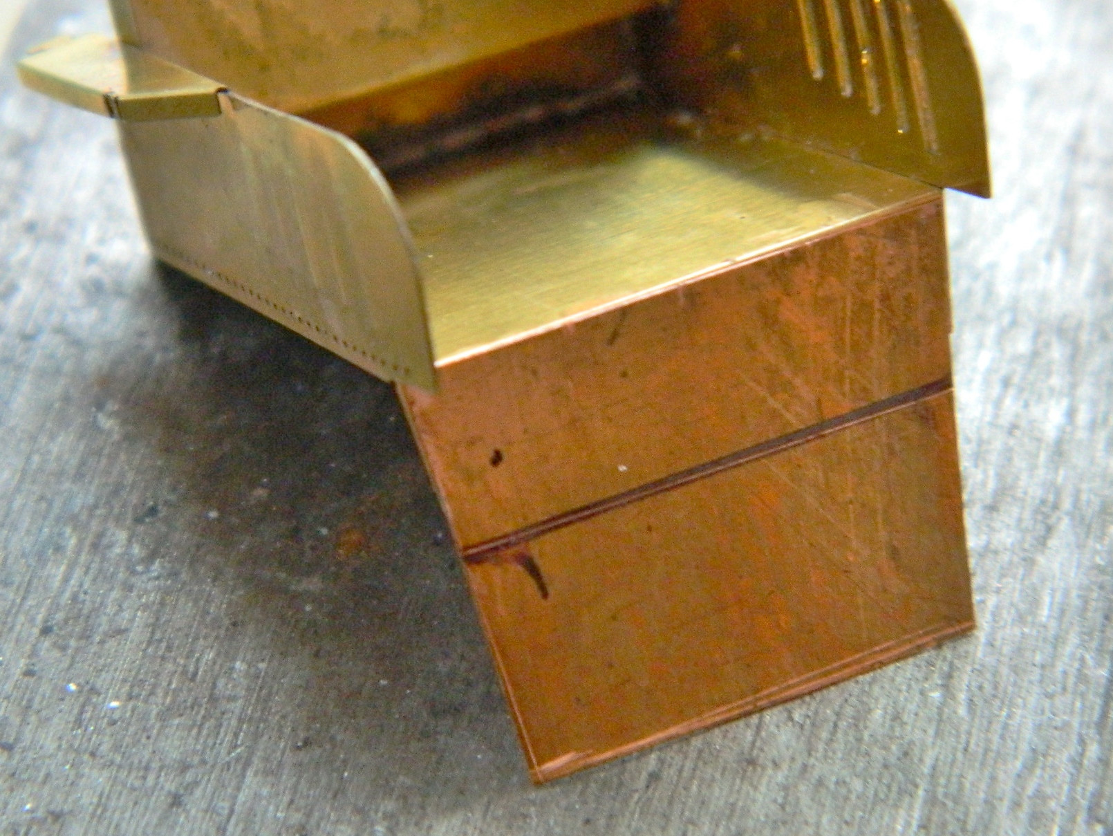
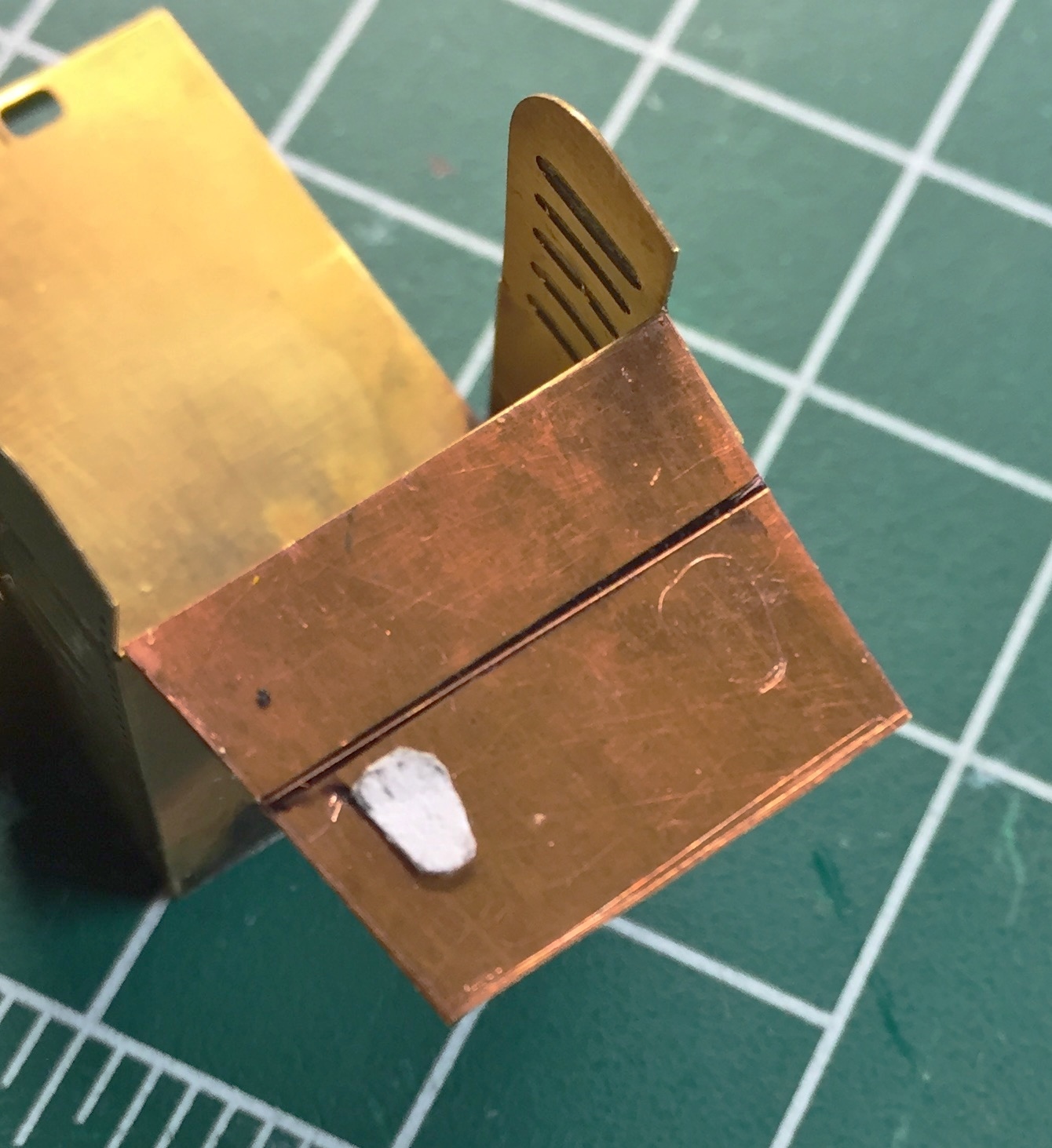
The ejection seats fill the interior. I’ve known since I assembled the PE parts (and decided that I wasn’t adding the astronaut figures) that I was going to have to detail them more than the PE set had. That started with taking the seats away from their backing. First step was making cushions. I had originally intended on making the cushions out of epoxy putty, taking a mold of them, and then casting resin parts to install. Then I realized I was making this far too complicated. I wanted to start with something about .070″ (1.778mm) thick and to do that, I needed to laminate sheets of .030″ (.762mm) and .040″ (1.016mm) to get that. Once laminated and cured, I cut them to dimension, shaped the bottom cushion, and then rounded the edges (and while you’re there, note how short the forward bottom face under the edge of the bottom cushion is…that has to be extended):

That worked well, and since there’s two seats, I needed to make another set:

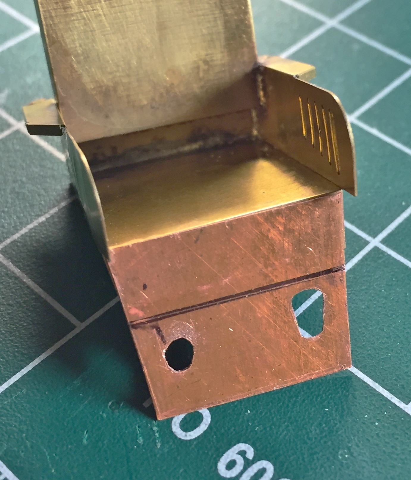
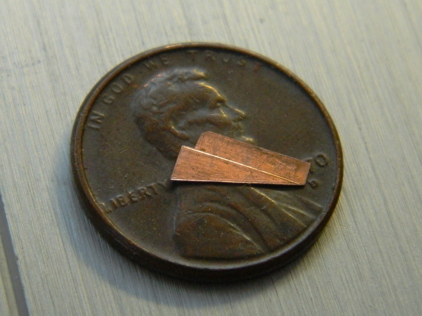
Then I had to extend the front vertical bottom face of the seat. I used .005″ (.127mm) copper shim stock and soldered it into place on the front, figuring the seam between the two parts would be easier to hide at the fold line.
A word about soldering…
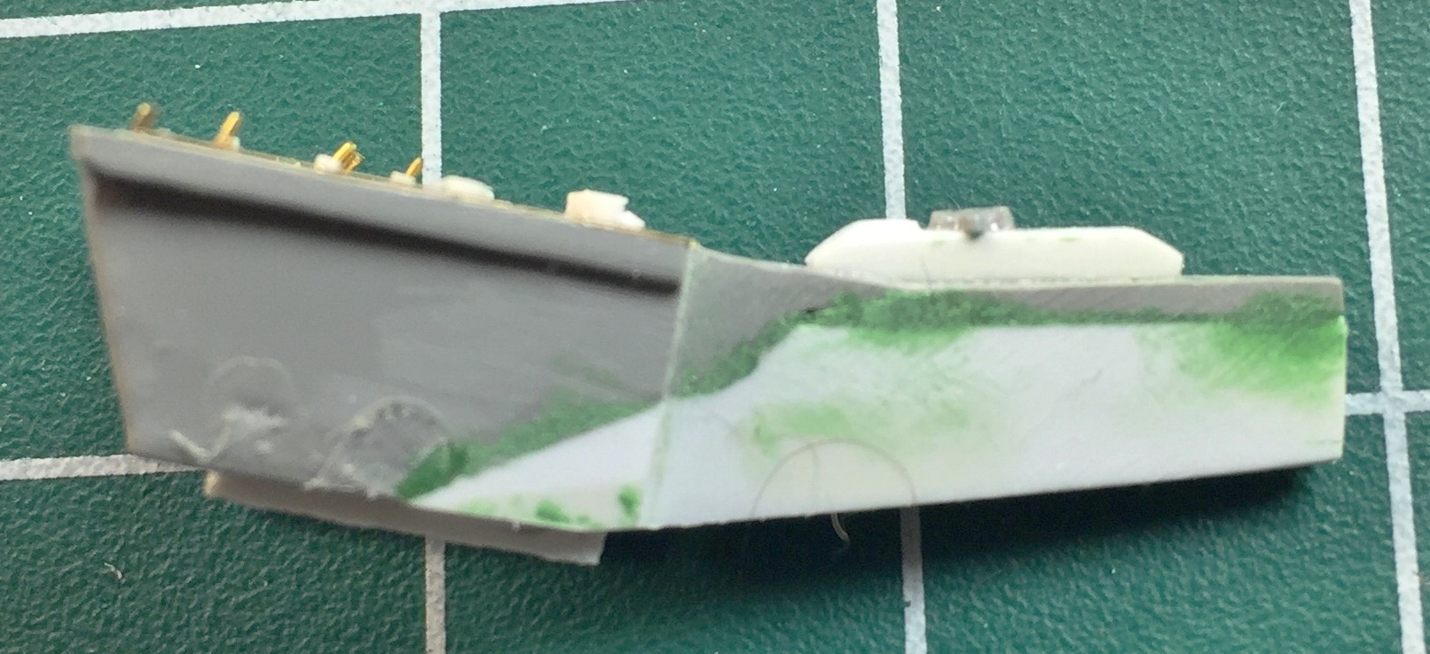
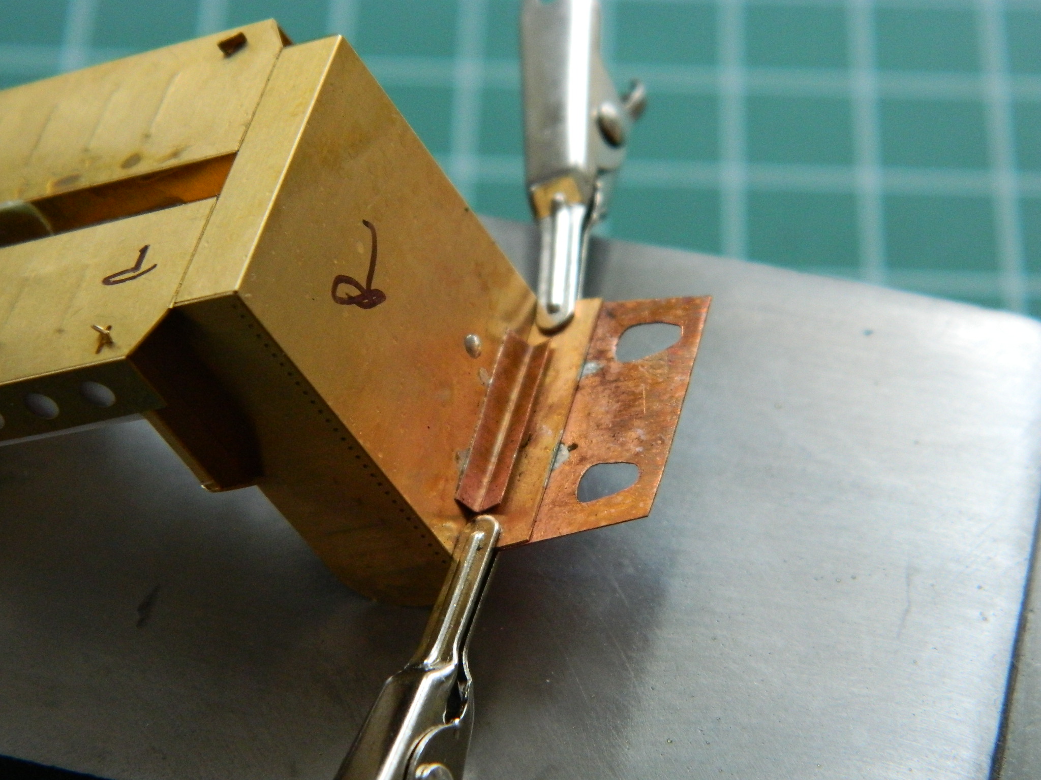
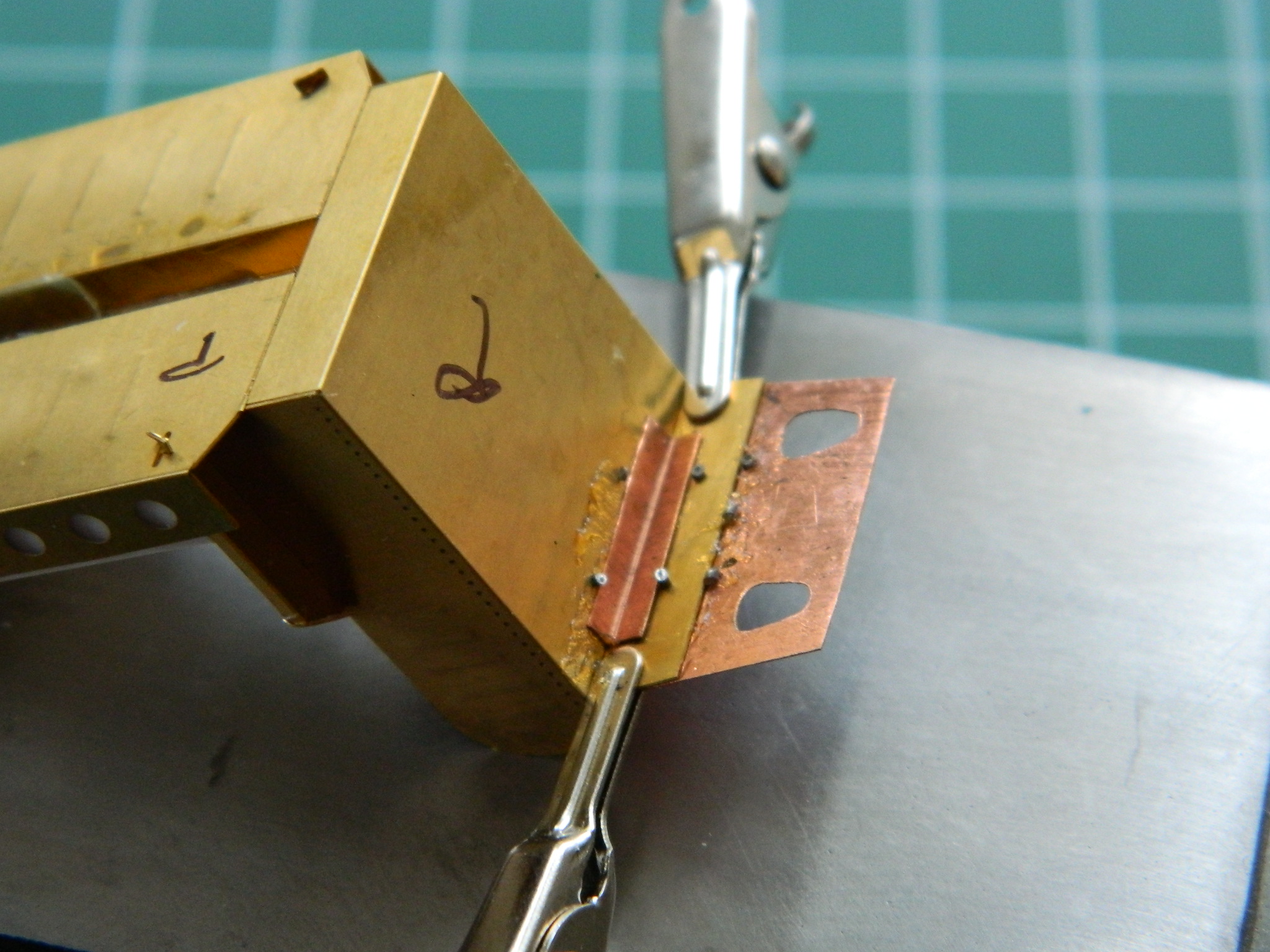
Using a soldering iron works fine for soldering small things that will heat up quickly. The soldering iron doesn’t do so well at heating up a large surface that heats slowly. For one thing, it only heats the area it’s in contact with. Fine if you want to solder something small at a small contact area. NOT so fine if you’re trying to solder a long(ish) part that’s been folded one too many times and has snapped off. It’s also not so fine if you’re trying to solder a wide, flat part to another wide, flat part…like I had to do with the extension to the front bottom of this seat, for which I used .010″ (.254mm) copper shim stock:

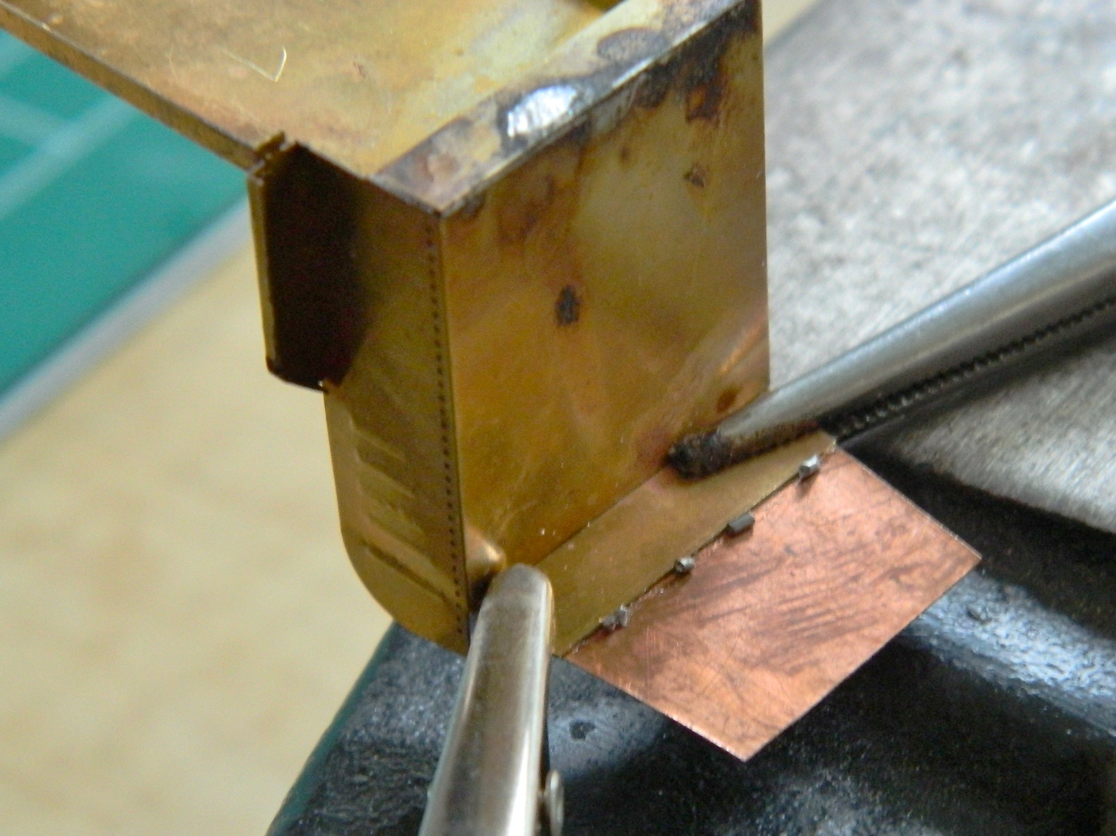
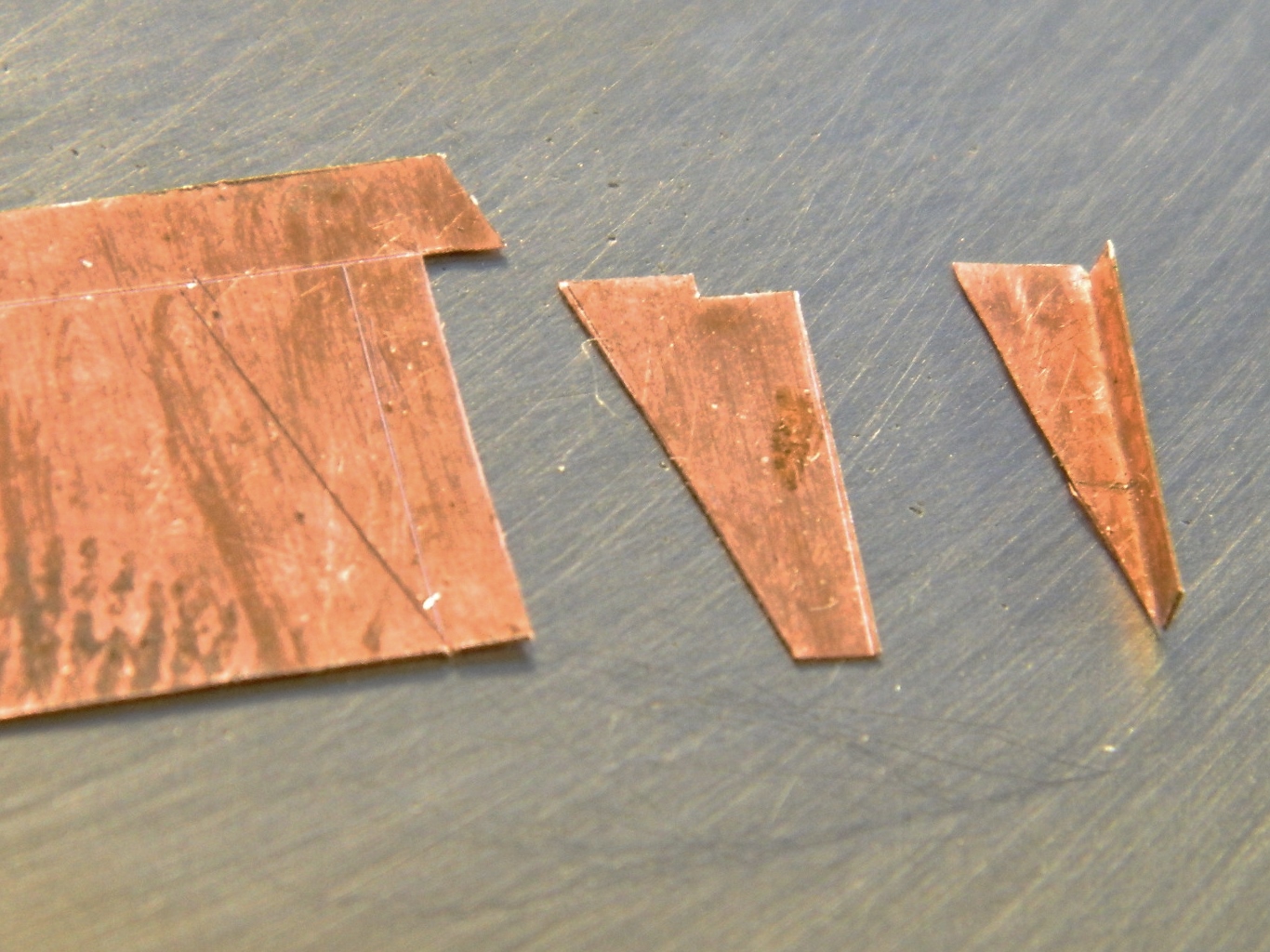
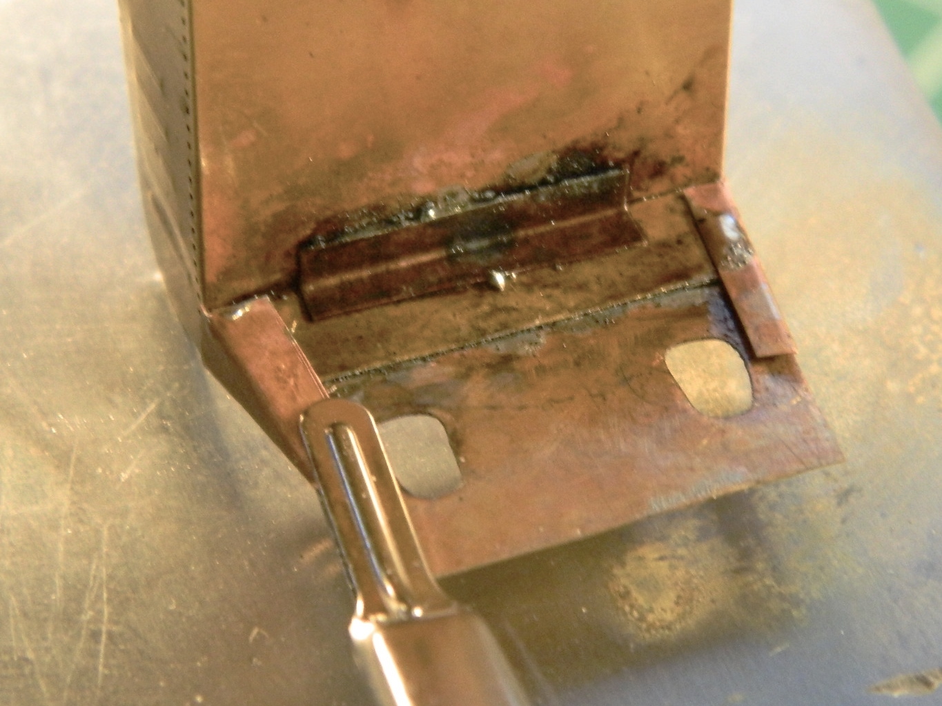
In the following picture, let me direct your gaze to the SLOP at the top center of the photo. This is where the seat back joined the seat bottom. It got dropped one too many times and snapped off. There isn’t enough surface area at the join for adhesives of any sort to work. I tried soldering it with a soldering iron and the charred lumpy crap you see is the results of my efforts. Yeah…it does hold the seat back to the bottom, but it looks like shit (and the only reason I haven’t redone it is because it does hold the back to the bottom and the shitty area won’t be seen). And while online looking for something else entirely, I ran across a soldering tip (idea, not something you’d attach to a soldering iron). Put a little bit of flux onto the part where you want the solder to flow and then clamp the two parts together. Then cut small bits of solder (as I learned, smaller bits than what I used here) and lay them in place along the seam of the join:
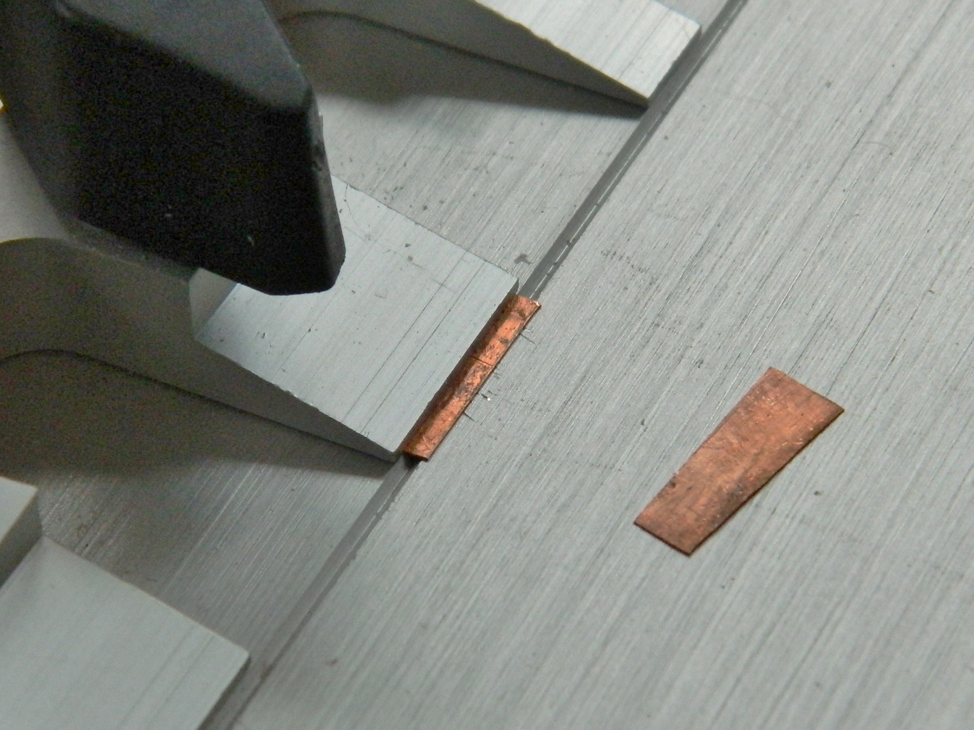
THEN use something along the lines of this little beauty. It’s a butane pencil torch (in case there’s someone from the UK reading this, I mean torch…not a handheld light source…which is what a torch is, I guess, but…well…I’m digressing a lot, here). A propane torch works well, also. It doesn’t take a lot of heat to solder:

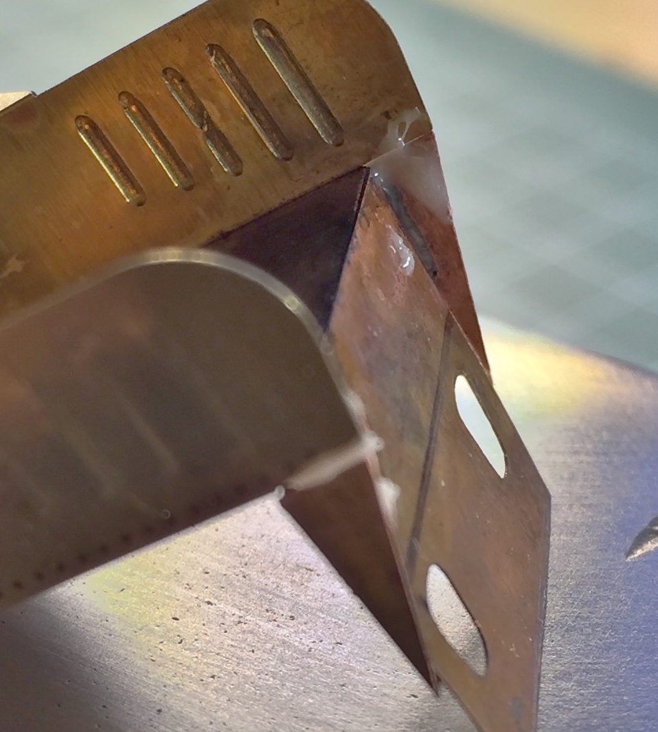
Fire that baby up and make several passes across the surfaces you’re soldering together, starting further away from it than you think it should be and then gradually moving closer. First the flux will liquefy and flow between the parts. Then the solder will liquefy and follow it. Quickly remove the heat source and you should end up with a nice clean soldered join:
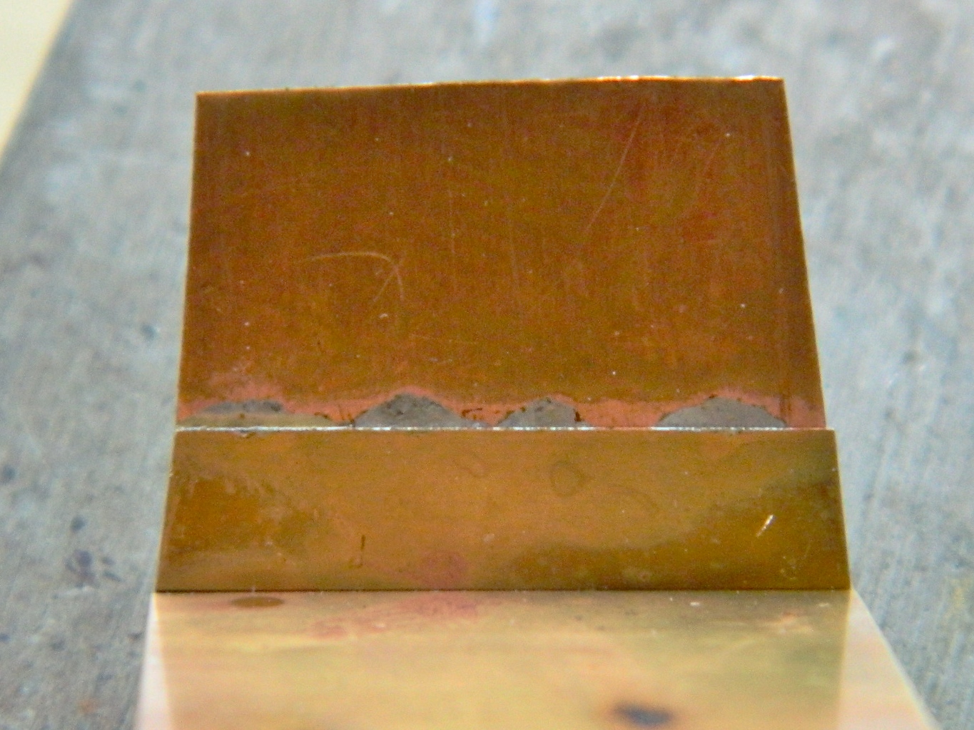
And that’s how I ended up getting that extension neatly attached.
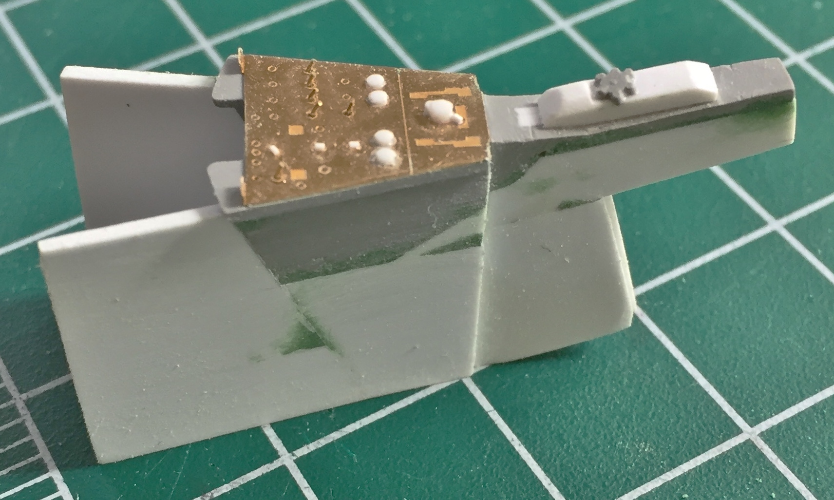
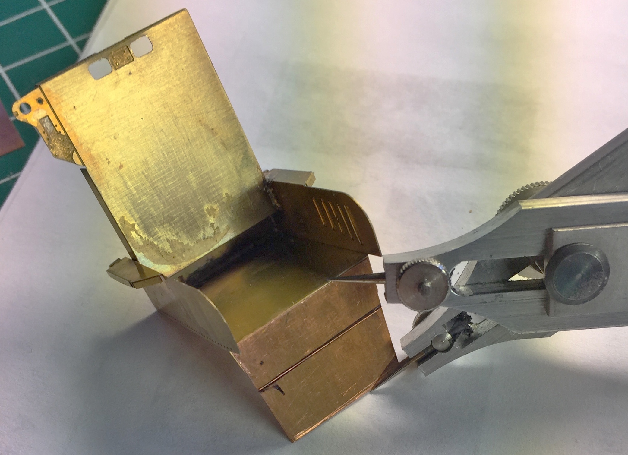
There are details that now need to be added and removed. Reference photos show the details on this area of the seat. To transfer the dimensions from a photo on my computer screen to copper parts on my workbench, I used these…proportional dividers:

By adjusting the pivot, dimensions of one scale can be easily reproduced in a different scale consistently. Reminding myself (again) that in modeling, things have to look right…in engineering, things have to be right (there is no “alternative engineering” any more than there is “alternative truth”). I placed the large spread of the divider against the screen and the small end against the seat front, and diddled with the pivot until everything matched, and then I took the relative measurements:

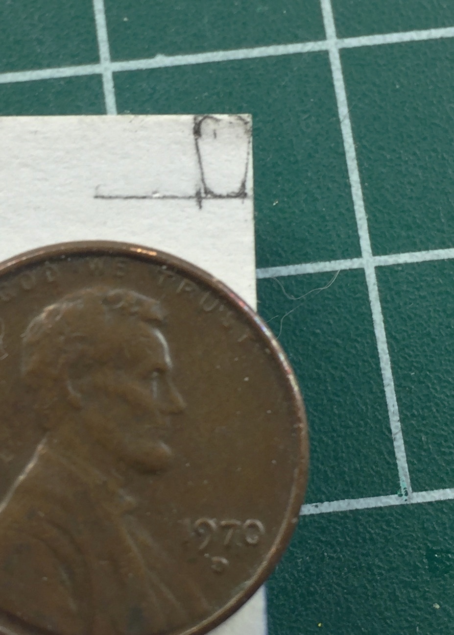
The details that are replicated by removal are those holes. I took out my Eyecrometer and made a template. Since this area is VERY small, I needed a template that would hold itself in place as my fingers are just too large. Masking tape “worked” but was problematic in use (too thick for the size I needed and more difficult to remove that I wanted to deal with). Instead, I used the sticky section of a Post-It note:
Then it was a matter of drilling and filing things to shape:
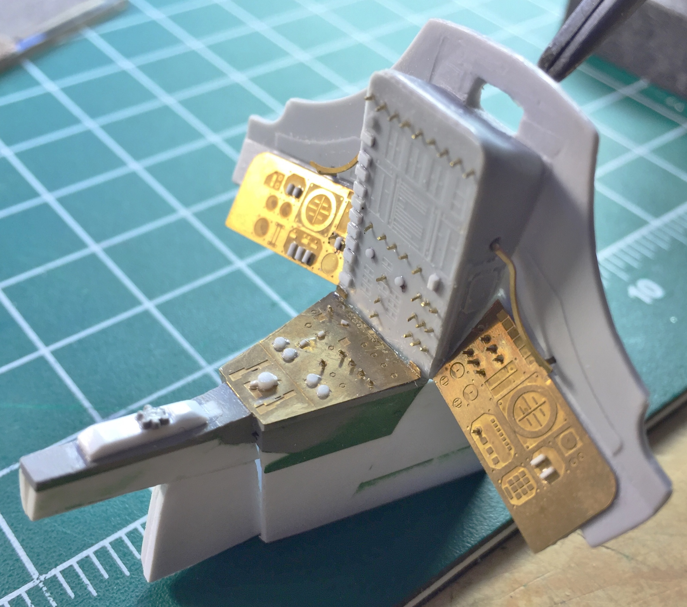
The sides of the seat come down further than the PE parts do and those needed to be fabricated and added:

Then I needed to fill gaps my ham-handedness left. I tried my structural putty which didn’t work. The gap was large enough for a piece of scrap plastic to be sanded to thickness and superglued into place. Then commercial putty was used to blend everything (hopefully) seamlessly:

Since there are two seats, that all had to be done again. Having made my mistakes (and rectifications) on the first seat, the second seat went much easier and was neater:

On engineering having to be right, I offer two qoutes:
An aircraft is a group of compromises flying in close formation.
Good, fast, cheap. Pick two.
Engineering often comes down to finding an acceptable answer to competing priorities. There often is no one right answer.
I’m looking forward to seeing this one finished.
LikeLike
The same can be said for cars. A series of compromises rolling down the road in a shiny package. (Some compromises work better than others.)
I’ve found problems don’t often have *one* right answer. First, let me get in the ballpark…then I’ll concern myself with where I want to play.
LikeLike
really great work.
LikeLike
Thanks!
LikeLike