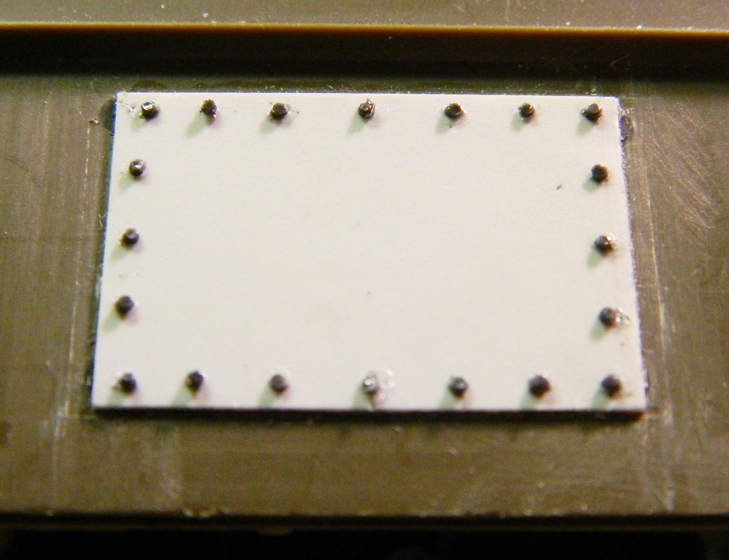
…and I still haven’t done any work fitting the engine. But I did continue work on the engine covers. I laid out where I have to add bolts later:
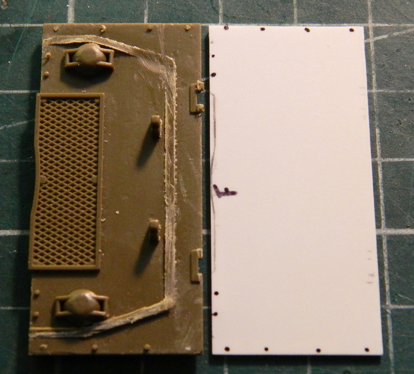
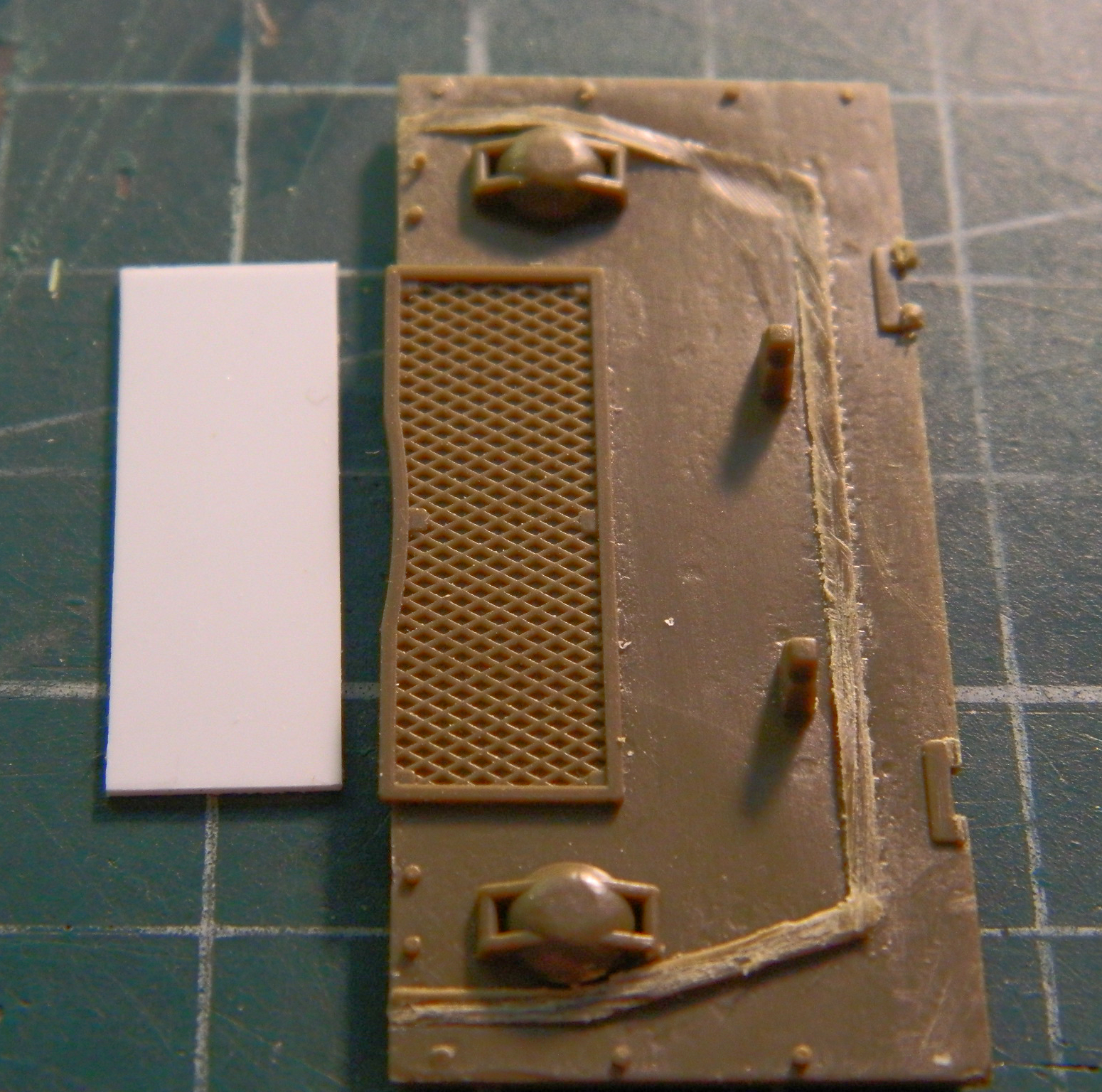
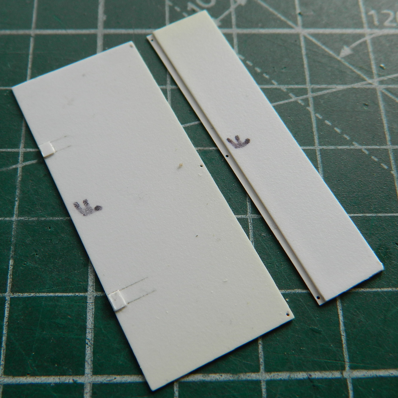
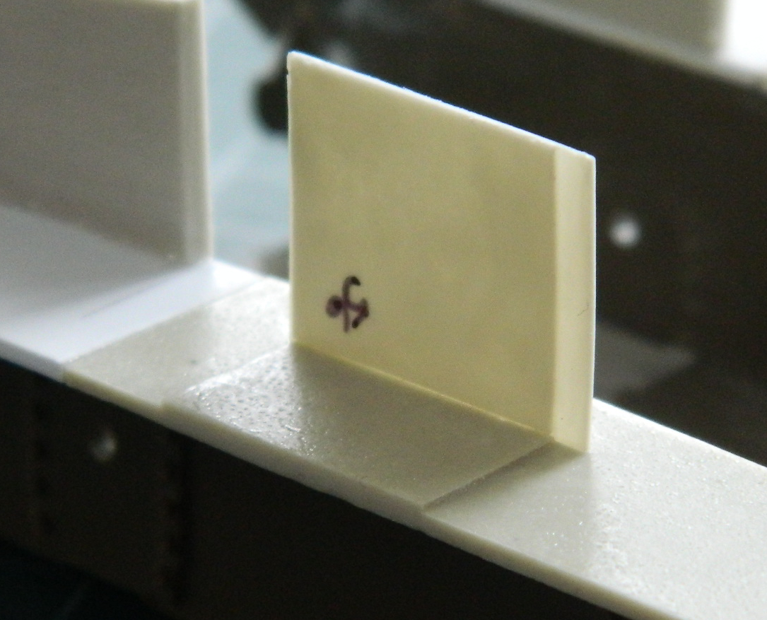
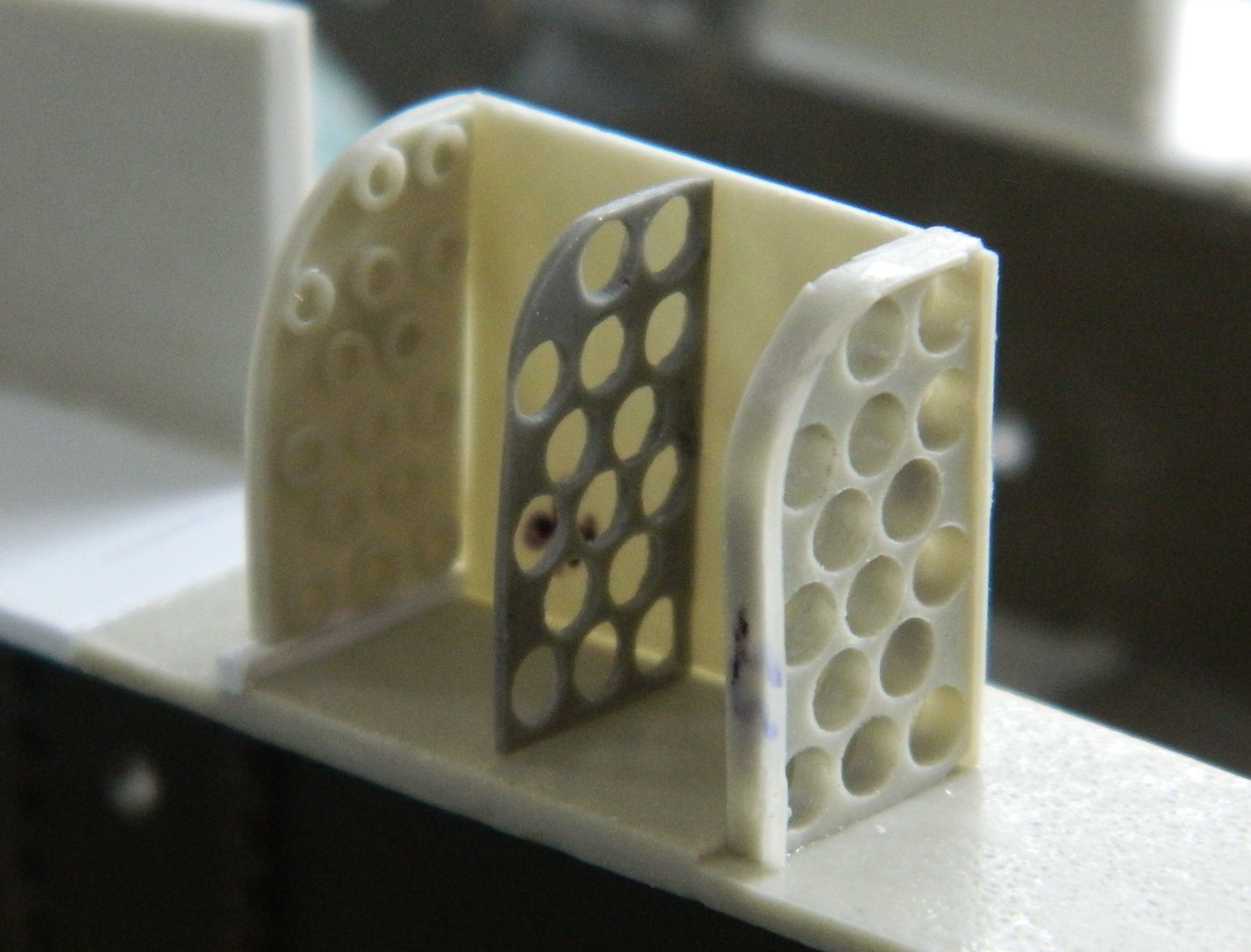
The air intake for the cooling fan is protected by an armored cover and a grill. With the armored cover close the grill isn’t evident. I made a blank to replace the grill:
I determined where the center of each piece is, aligned them, and glued them together:
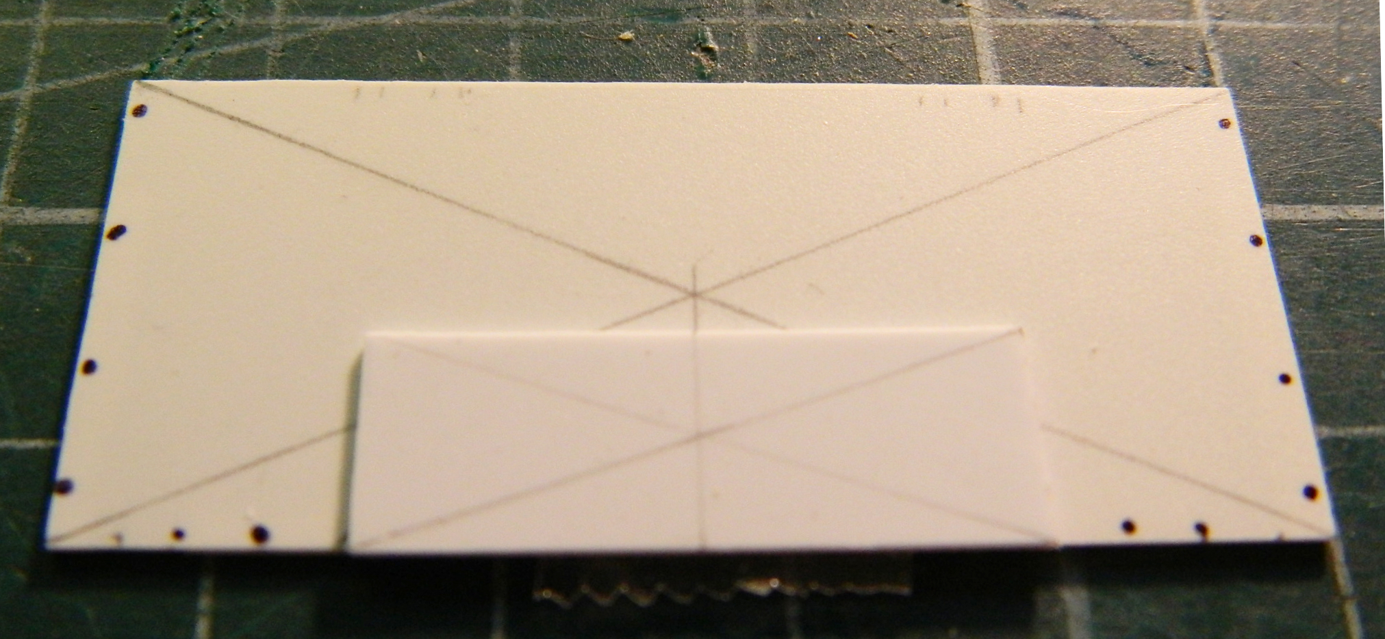
I clamped the two parts together using reversed clothespins:

Setting that aside to cure, I realized that the upper hull over the engine was too thick for scale. Yes…I have a ruler in 1/35 scale…and no, the top of the hull over the engine was not 2″ (50.1mm) but more like 1″ (25.4mm):

That’s better:

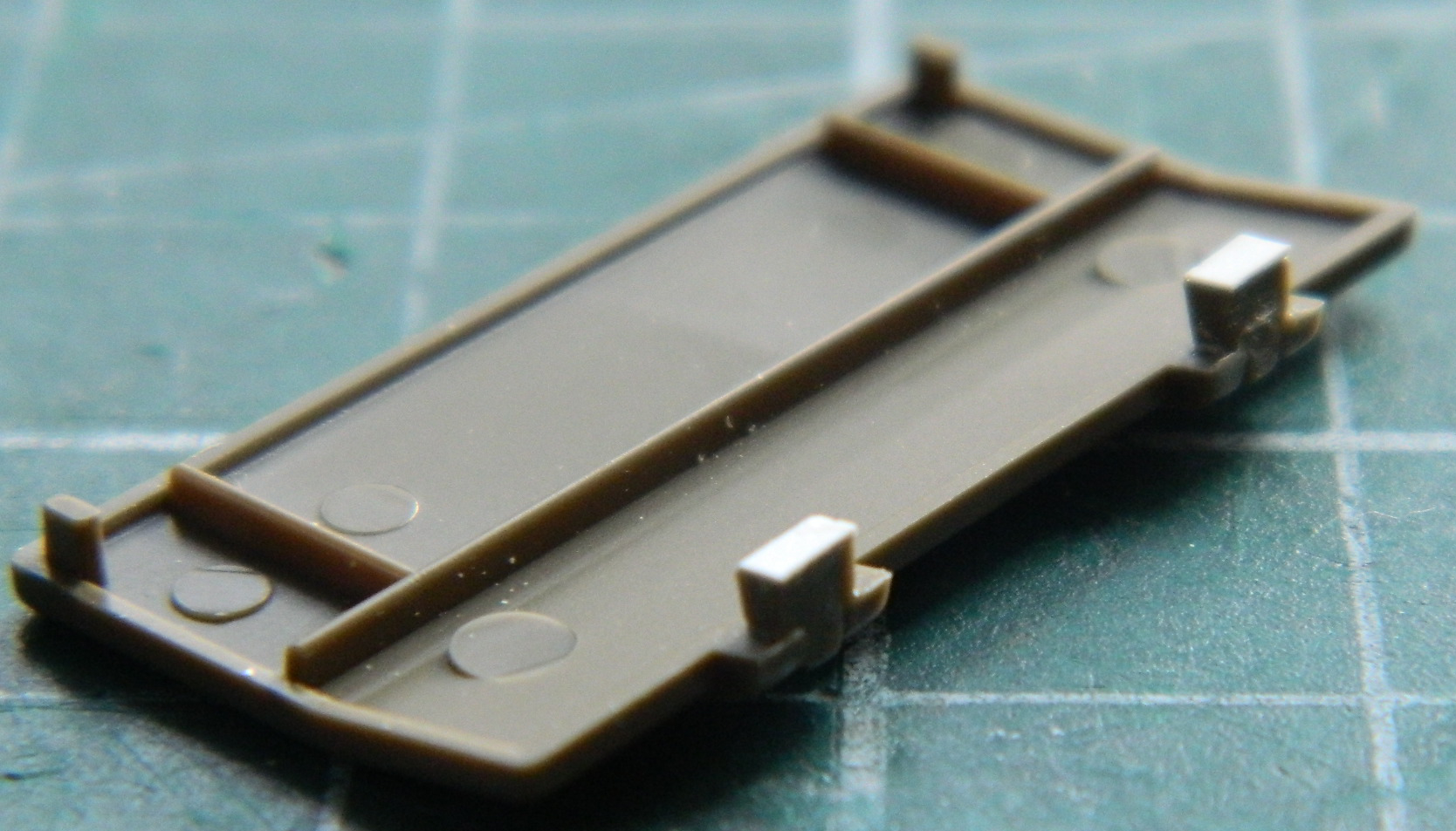
Rather than trying to reproduce the armored air intake cover, I cut the kit part off and used that instead. To start that process, I glued the cover onto the kit’s engine cover and then cut the rear mounts (which are actually hinges) free and then used .010″ (.254mm) scrap to replace the kerf.:

At this point I was still trying to make the hinges for the engine cover operational. I drilled out the rod to allow the hinge pins to seat and then glued the hinge parts to their respective locations:


I let those parts set overnight so that the glue was totally cured before I checked the hinges’ function. I didn’t have much faith that the hinge parts would hold given how incredibly small the contacts are between the hinges and plates…and that’s not even considering what operating them would do. I was correct, however. The hinges failed immediately:
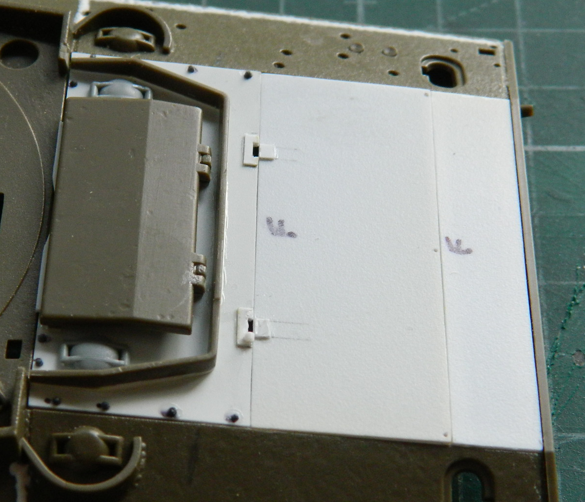
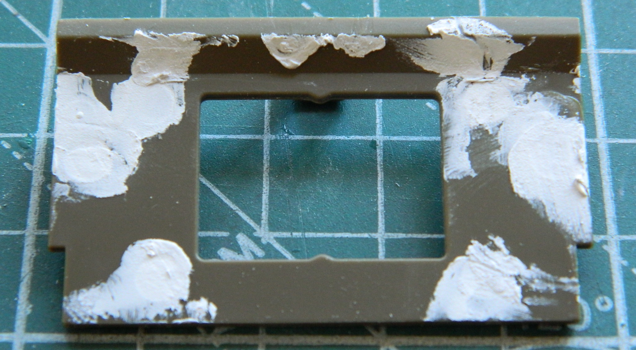
And here the entire notion of “operable” is tossed. I dug through my spares for a pair of armored fuel cap covers (Dragon parts, I think, and substantially better than what Tamiya had molded on), glued them in place as well as the armored vent cover as well as adding the bolts that hold this panel down:

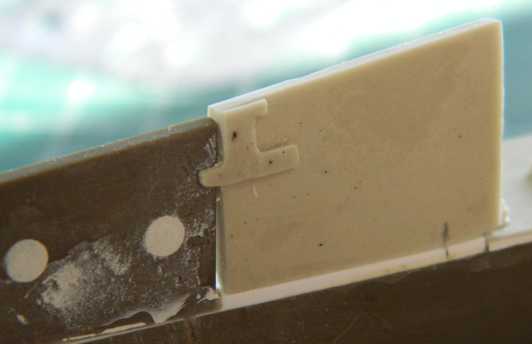
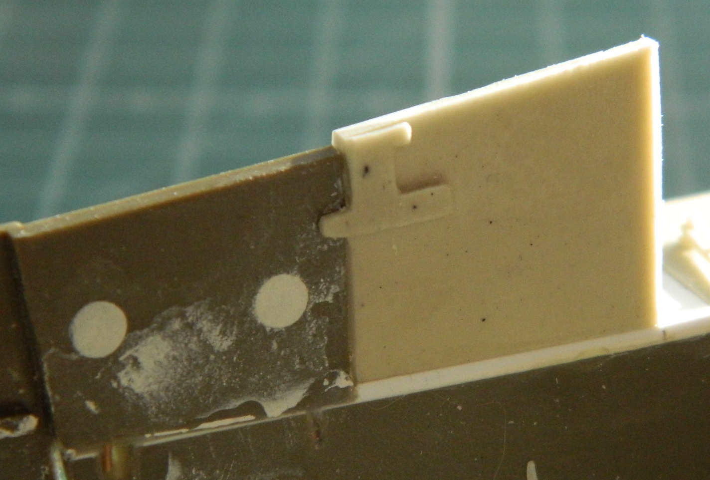
There are three panels that comprise the engine cover. The one I just finished making, the panel that hinges open for minor engine maintenance, and the rear-most panel which is welded on. The opening panel is bolted closed so I added a lip for it to bolt to using .005″ (.127mm) styrene and drilled the bolt holes (later on I added three bolts just laid on top of the rear-most panel):
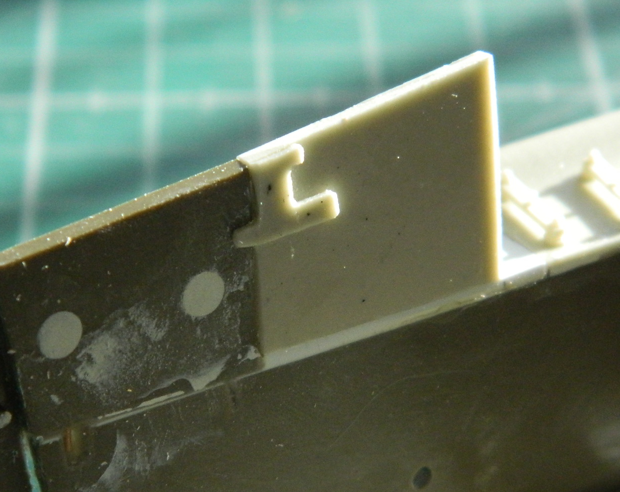
A quick check (of many) to be certain everything fit as I wanted them to (and hopefully I was correct). I’ll add the cylinders for the hinges later:
With the distraction of hull work attended to, it was time to turn my efforts back towards getting things ready in the crew compartment. One of the things I had to do was to make a clevis to replace the one that got lost. I used a piece of resin pour block instead of styrene because of how flexible styrene can be. This is a really small part and I wasn’t confident that the plastic would hold up while I cut and whittled the shape I needed. Resin can also be flexible, particularly when warmed, but a quick dunk in cold water returns its rigidity. That process started with cutting a small piece of resin to work on:

Cut a slit to open up with my dental grinder:
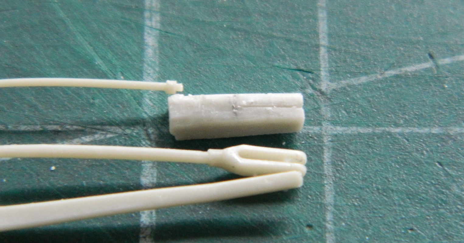
And then started cutting and carving…using a VERY SHARP scalpel:
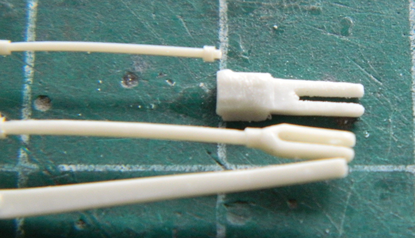
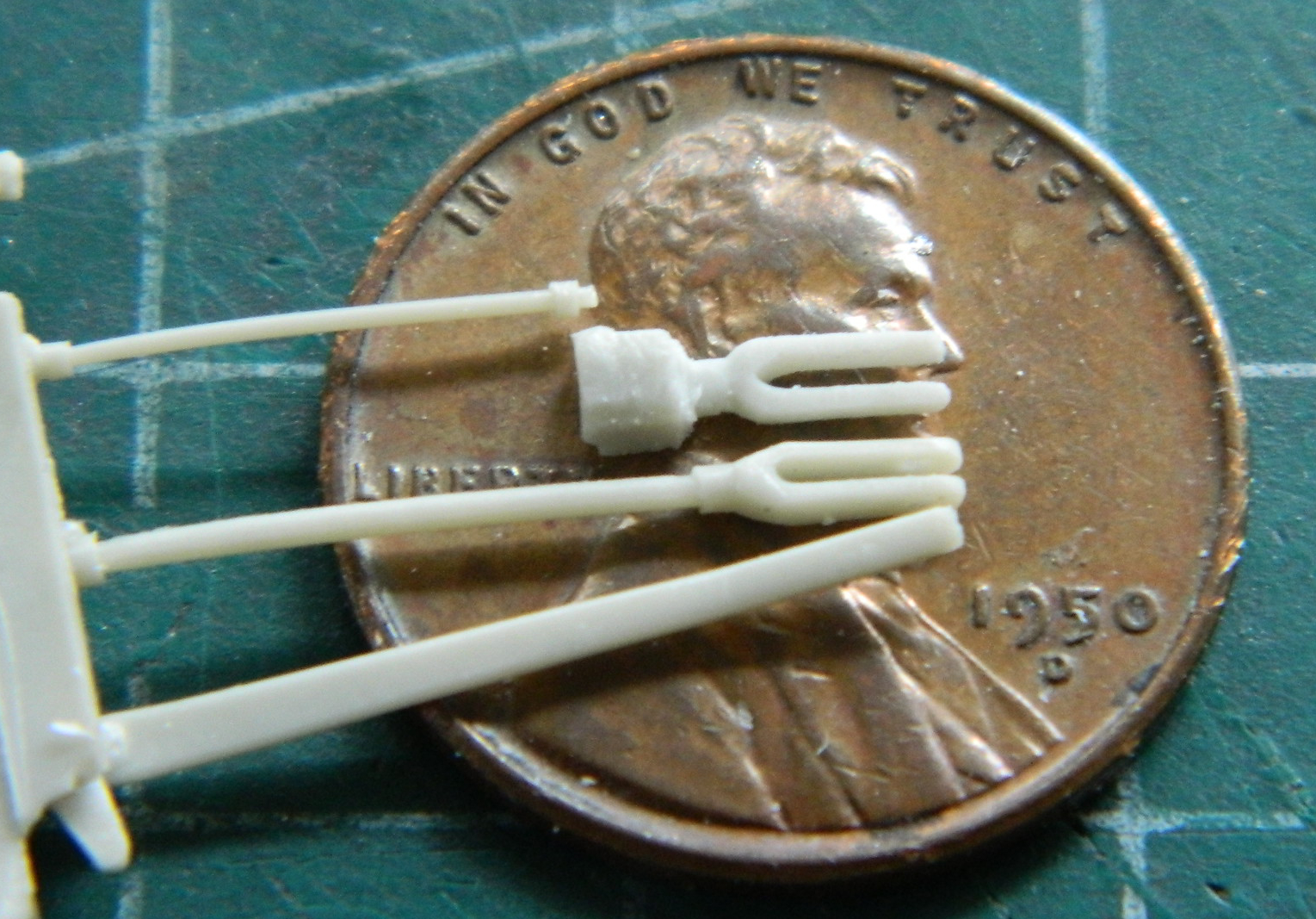
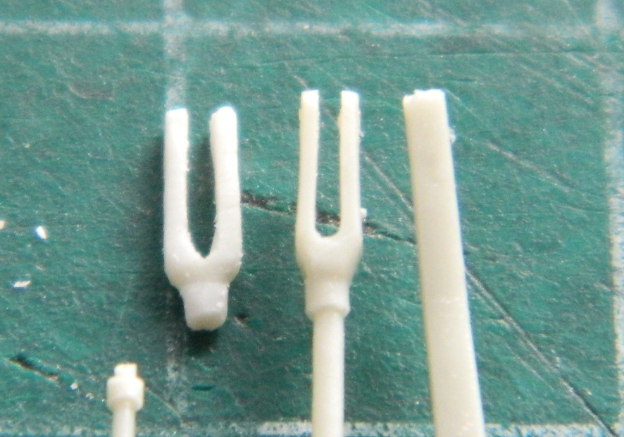
The part isn’t identical to the other, but it shouldn’t be noticeable once the part is in place (and nowhere near as noticeable as it’s absence):
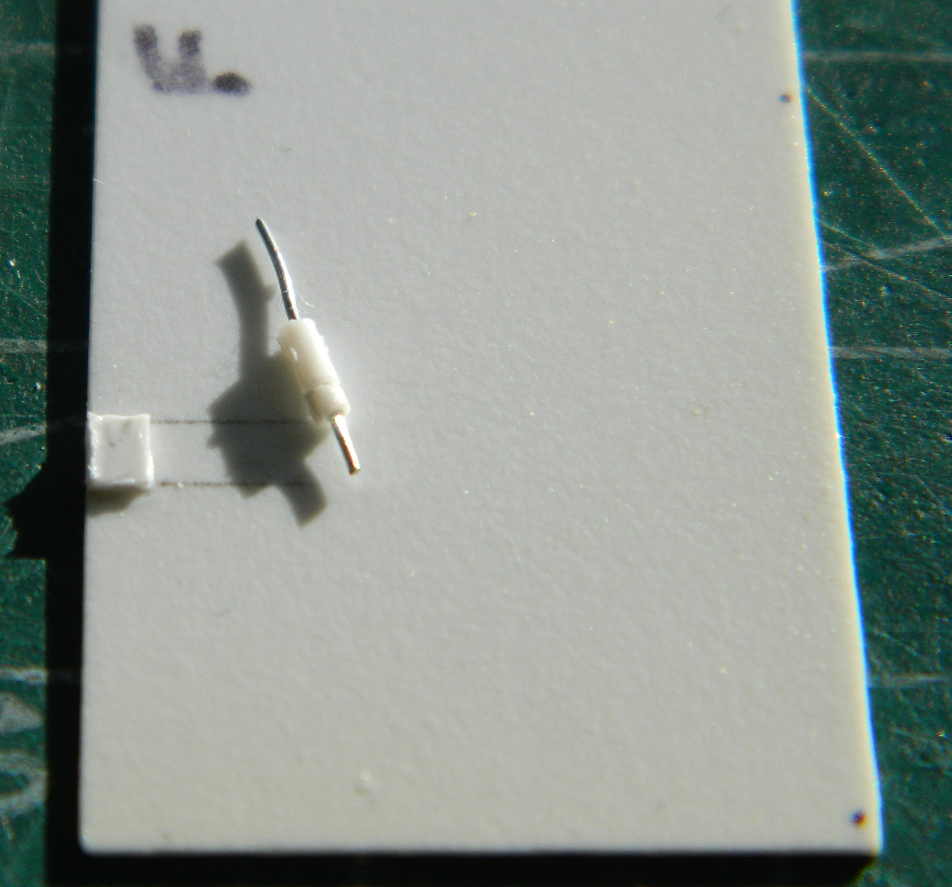
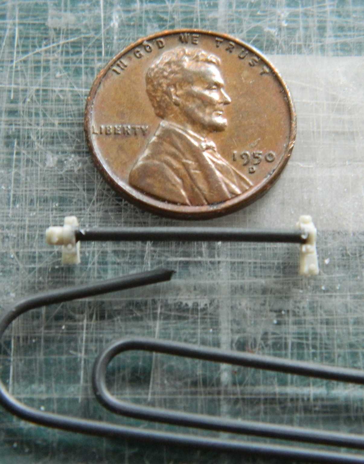
There is a torque bar that is part of the clutch linkage. The resin shaft broke so that had to be replaced. I noticed that a paperclip was the same diameter so cut one and fit it as a replacement:
Last summer, I looked at CMK’s website to see if they had any more of these interior sets and they didn’t. That’s why I made copies of the one set that I had and why I’ve been trying to avoid using the PE that came with the set. But the next thing I had to make was provided for in this set in PE. It’s one thing copying a basic or simple shape on shim stock. It’s a different thing when the shape is neither simple nor basic. So four months after the last time I checked, I went back to CMK’s website to see if these sets were still being produced. Yes, they are! (Wish I’d known that before I spent more money than I care to mention on molding rubber.) Instead of making an inferior copy of the PE part, I used the PE part (now that I know I can get more):
With that bent and glued, I had all the subassemblies I needed to be able to check fitment. So I checked fitment. It all fits in much the same way an actual M4’s things fit. TIGHTLY:

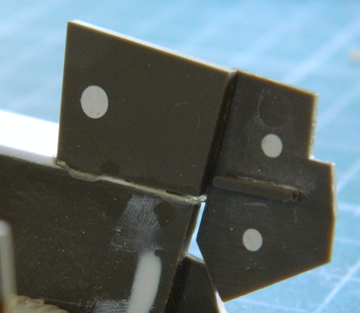
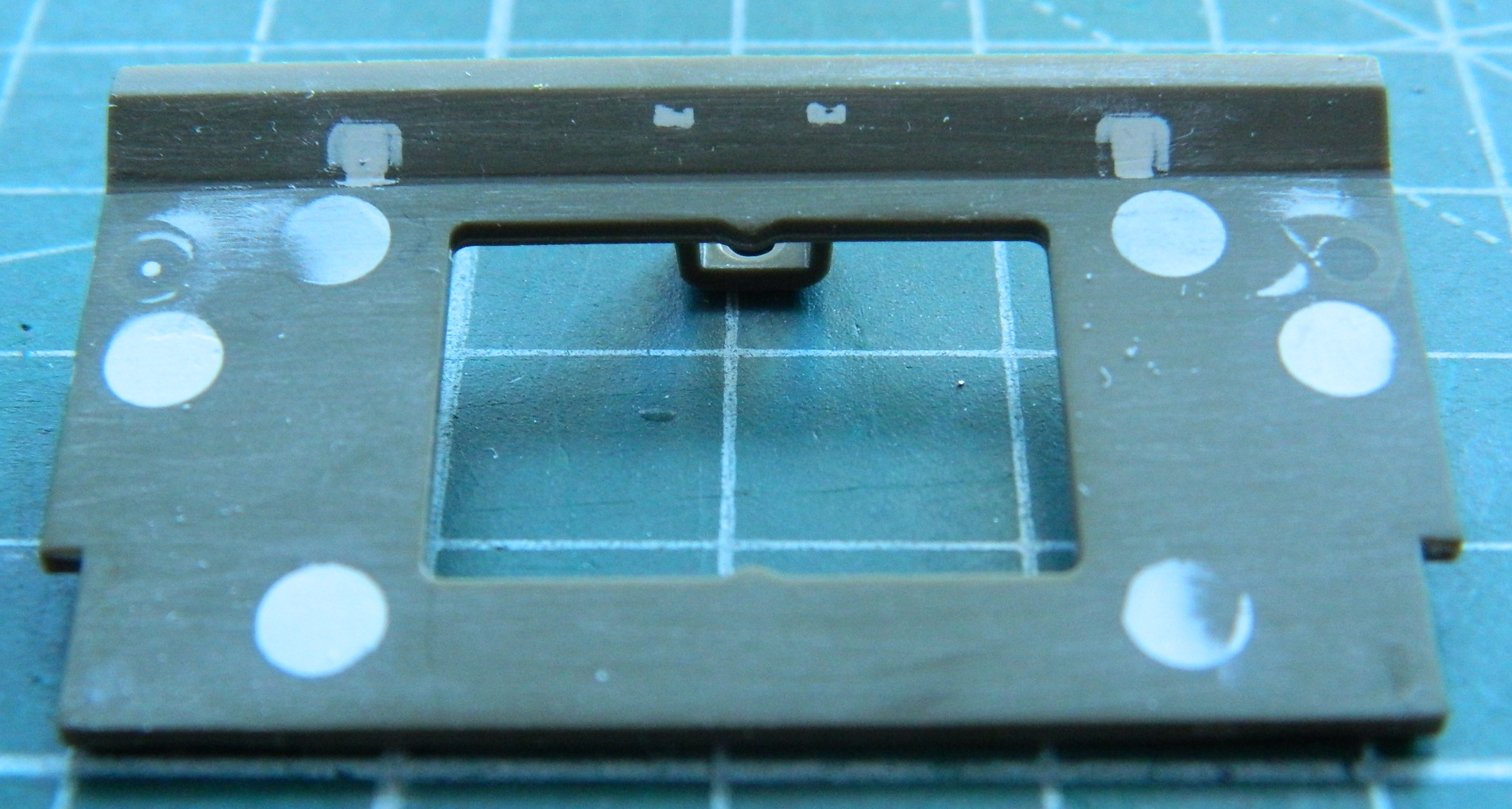
When I’d extended the sponsons, I neglected to check at to why the sponsons were shorter. That’s because there are kit parts that provide the upper inner sides for the engine bay. After briefly kicking myself for a seeming error, I realized that I was going to have to add the sponson extensions anyway, though it probably would have been easier on me to add them later. So it goes. But that meant I had to get rid of the extra .030″ (.762mm) so that the sides, which are also supports for the rear upper hull, don’t stick up too high. Much carving and scraping ensued yet I prevailed. I thinned out the styrene I’d added to about .005″ (.127mm) and then added wire pins to the kit part. I’d intended on socketing them into the tub sides but totally bitched that one up. Then I reminded myself of what the pins are for. They’re there to provide structural strength and added gluing surface. Well, I can do that just using superglue…I don’t need the pins to fit plastic tightly, just that they’re held in place tightly. Superglue filled the void I cut out and that part is ON there permanently (the white circles are filled ejector pin sockets…Tamiya never expected this part of the model to be seen):


When I did the other side, I didn’t bother with pins at all:

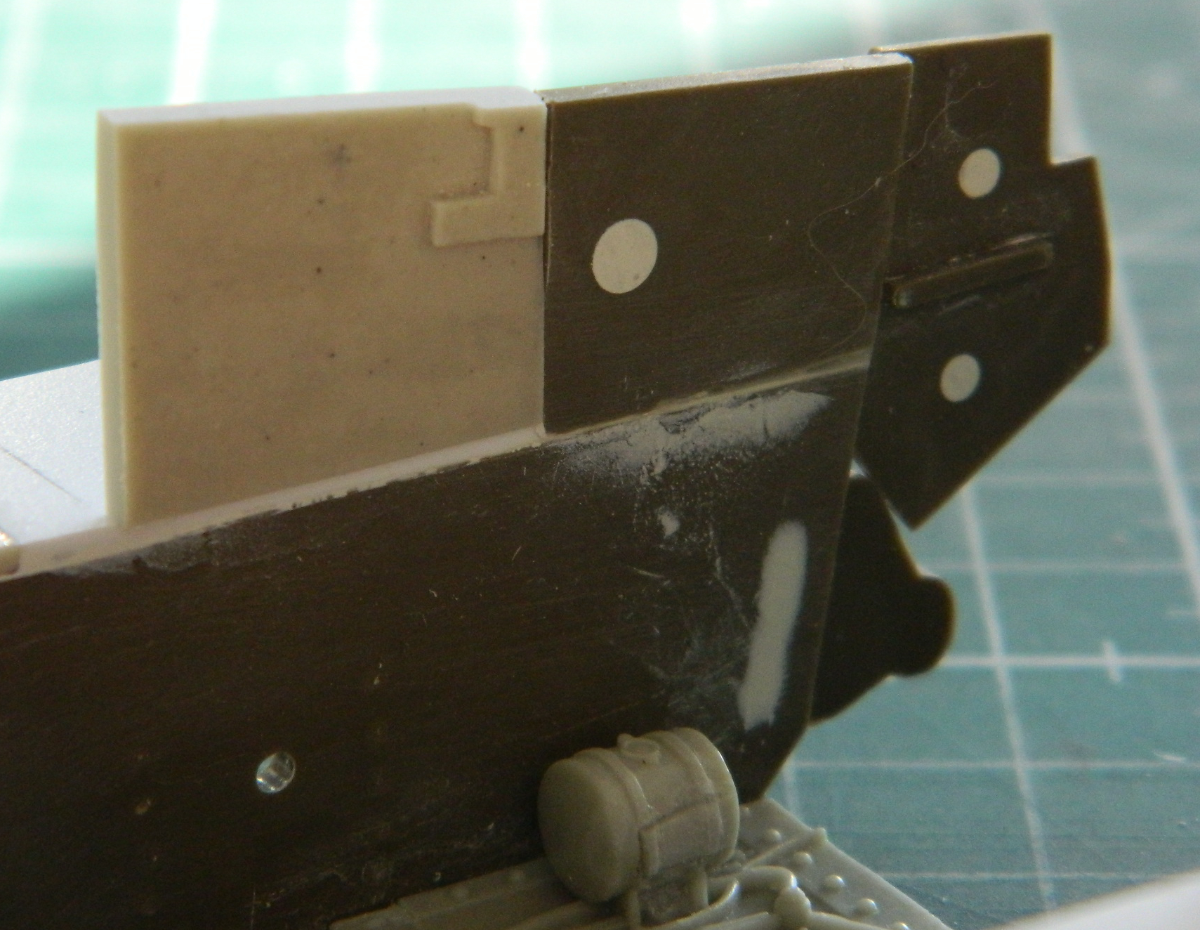
The resin parts that extend the upper wall of the engine bay were too long. They were too long because someone out clevered himself. Again. I figured out where they’re supposed to end, marked them, and then cut them. And during dry-fitting, I realized that this part also didn’t count on having a layer of .030″ (.762mm) styrene in the way. This time, though, it was a much simpler shape and I could remove the excess from the bottom:
No, the resin parts didn’t fit well, probably because of how “clever” I was:
A bit of filing improved the fit:
Then I removed some of the bottom of it to dial (or file) in the fit and all gaps were filled with superglue and filed smooth:
What’s pushing the build at this point is getting things ready for the shadow-coat for pre-shading. In other words, paint things black. I don’t know how much of the rear of the engine bay will show through the open engine cover, but it’s SO much easier to “fix” now than later if I do need to fix it. I added the pintle mount and puttied all voids inside the rear plate:

When I extended the differential cover, I knew I was going to have to putty things and then put the texture of a roughly finished sand-casting back. This is my first time using Mr. Surfacer 500 and rather than put the build at risk, I found the same differential cover in my spares and tested it there:

Pleased with the outcome, figuring I can sand/scrape the surface into a closer approximation of a cast surface, I did it again on the build:

Sanding and scraping gave me the look I was after. And before I populated the sponsons with all sorts of fragile resin parts, I decided that while the sponsons were still bare I’d also add bolts to the bottom of the differential cover and the engine inspection cover:

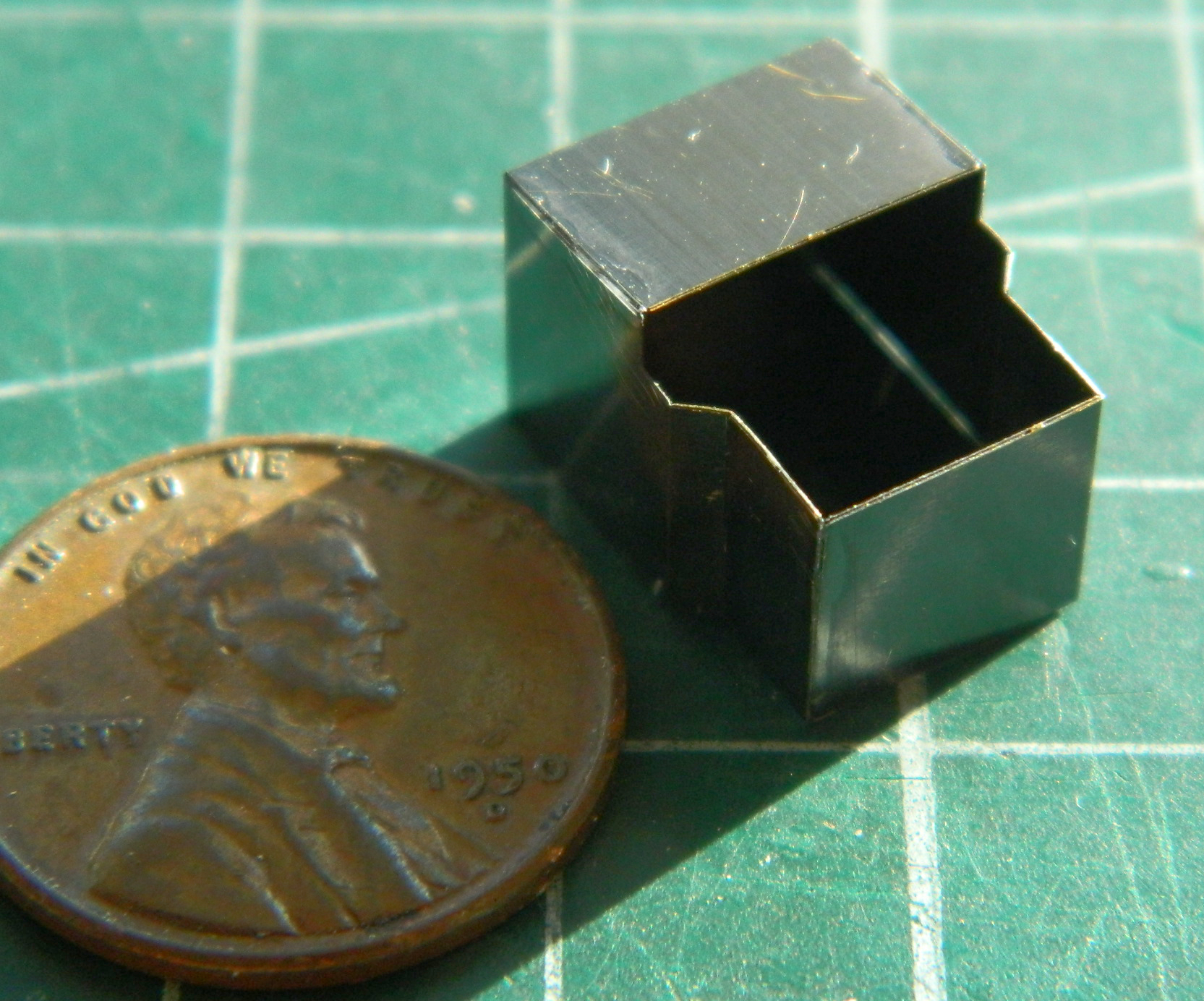
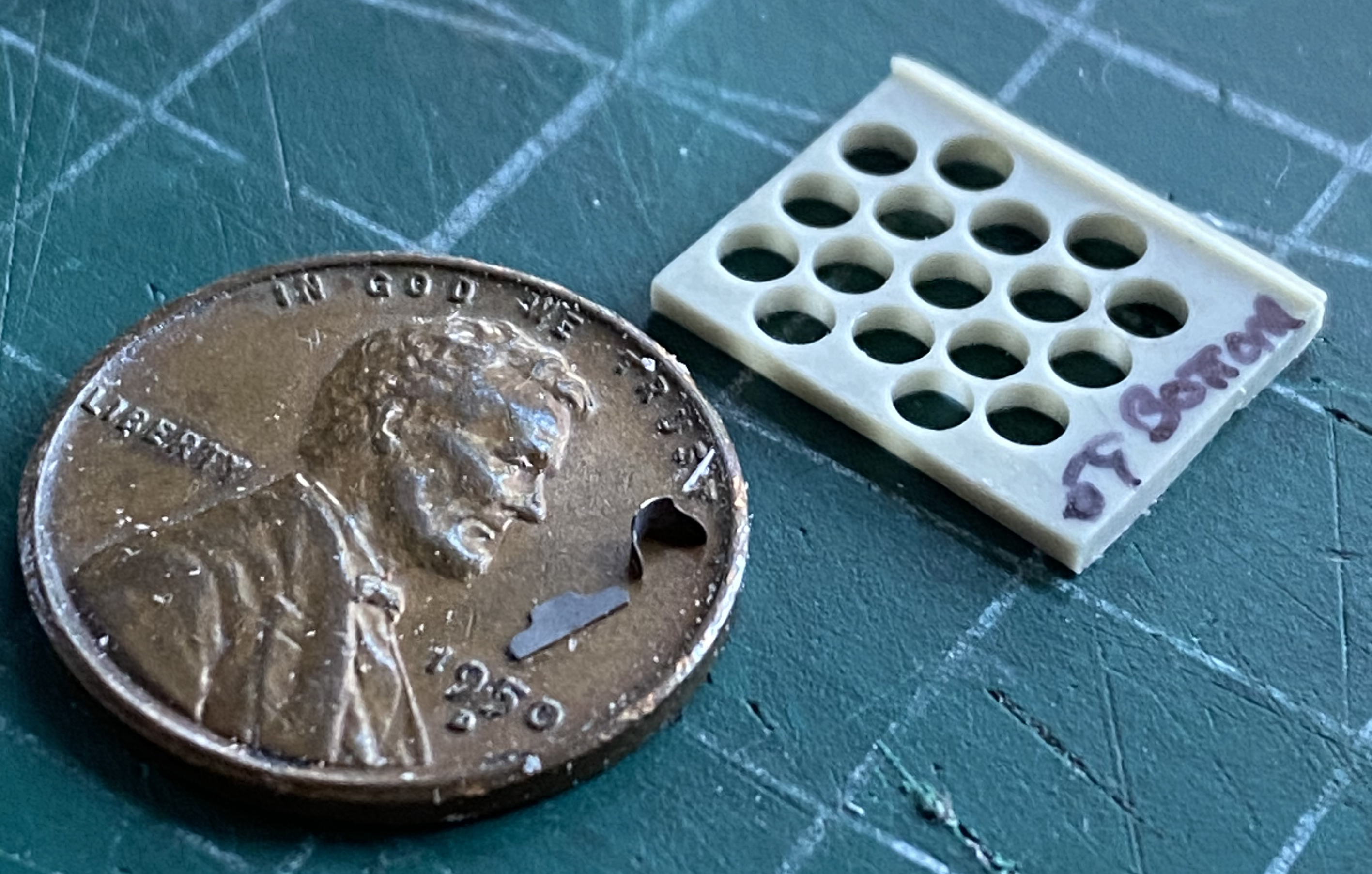
Dry-stowage Shermans had their main gun ammunition in racks behind thinly armored sides. There are guides (and probably latches) on the ammo racks to hold the rounds securely in place. There are lots of those things in PE. I needed to bend those PE parts to an even and consistent curve. Friend of mine gave me the idea on how to jig them so that I could get the even and consistent curve I needed. It started here. The guide is on the penny and where that guide (and many others) needs to go is shown by one of the rack’s faces:
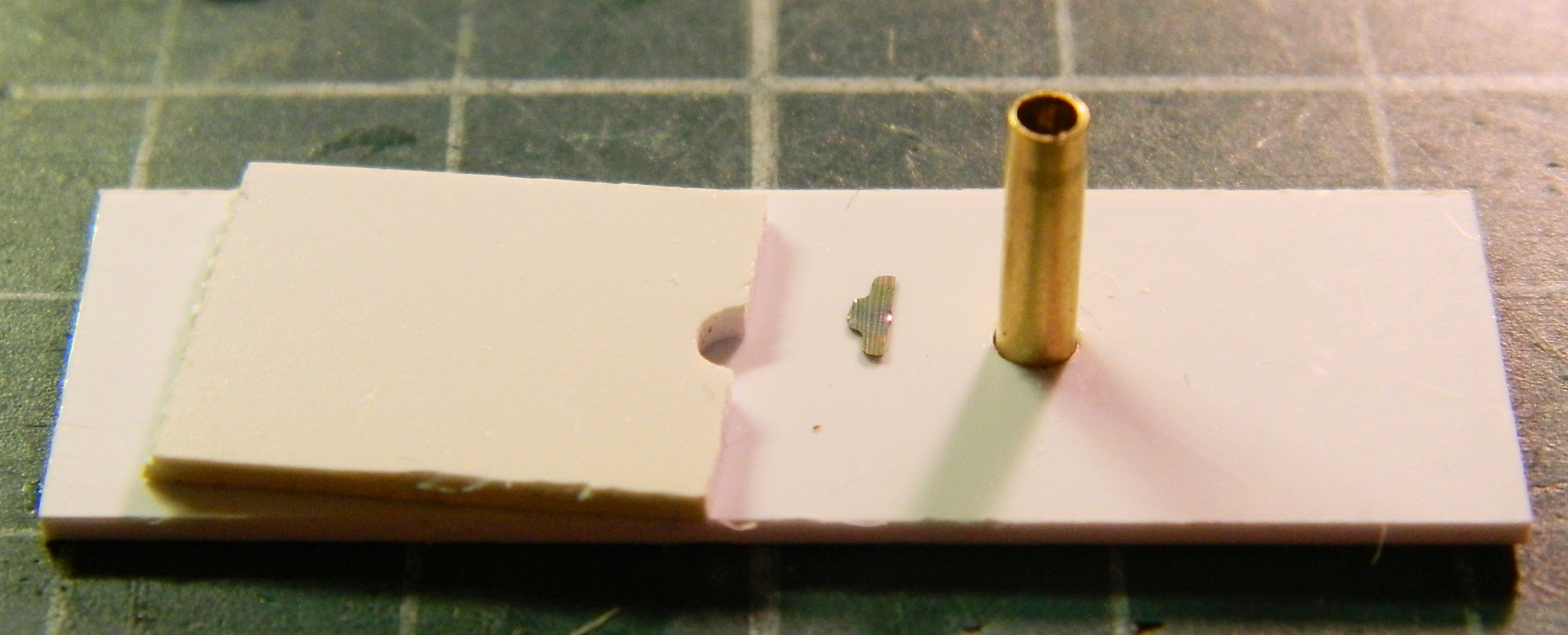
To make the jig, I used an empty casing from Tamiya’s #35191 Brass 75mm ammunition set. I used .040″ (1.016mm) styrene and cut the required hole in two of the styrene scraps. Then I cut across one of them. The uncut scrap had the casing inserted from underneath and the cut scrap was used as the ram to form the PE around the casing:
BEFORE even attempting to bend the PE I annealed them first (heat them up bright red and let them air cool at their own pace…makes bending PE much easier). Then I put a very slight bend in the PE, more to allow it to stand on its own than to shape it:
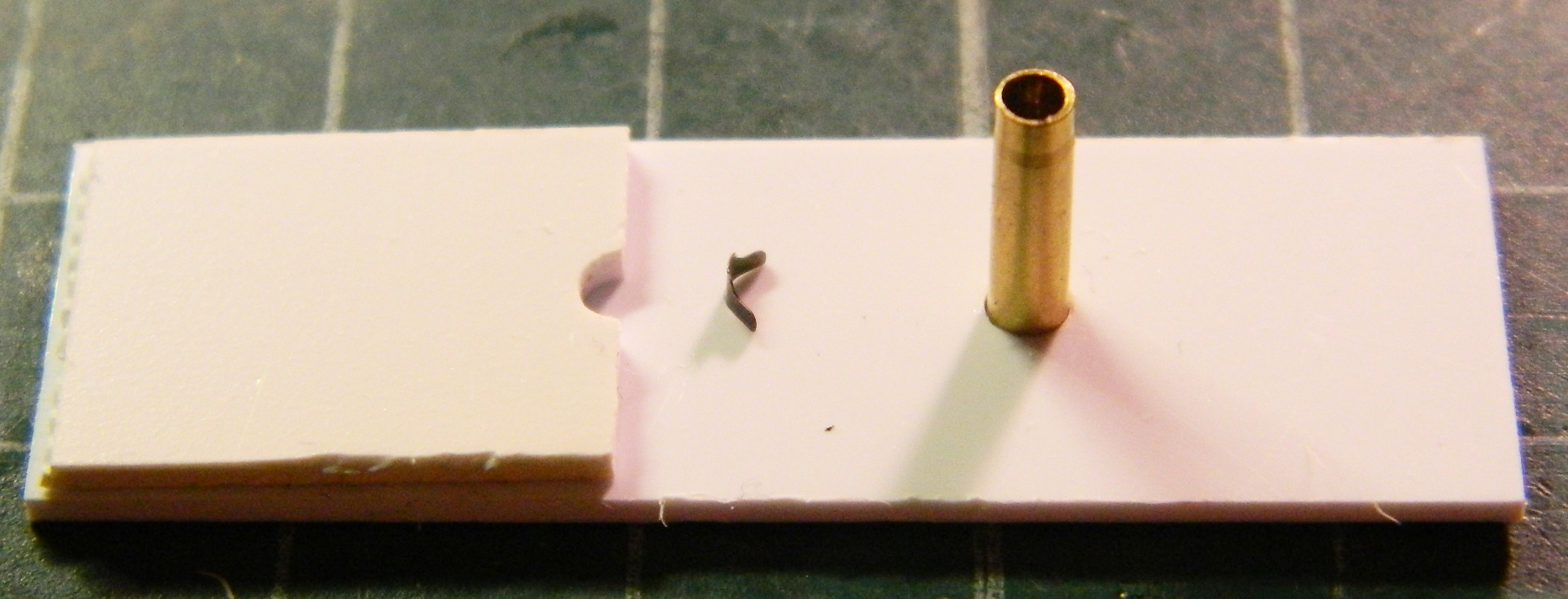
Then I centered the PE on the ram’s cut out and pressed it tightly against the casing, using tweezers to bend the wings completely around and snug against the casing:

Then result worked…and I only had to do it another 31 times:

And this is where the wheels came off this particular cart. Not only aligning the guides to the holes AND trying to keep the PE part on the resin and not stick to the needle I was using to transfer superglue, but to make them all the same:
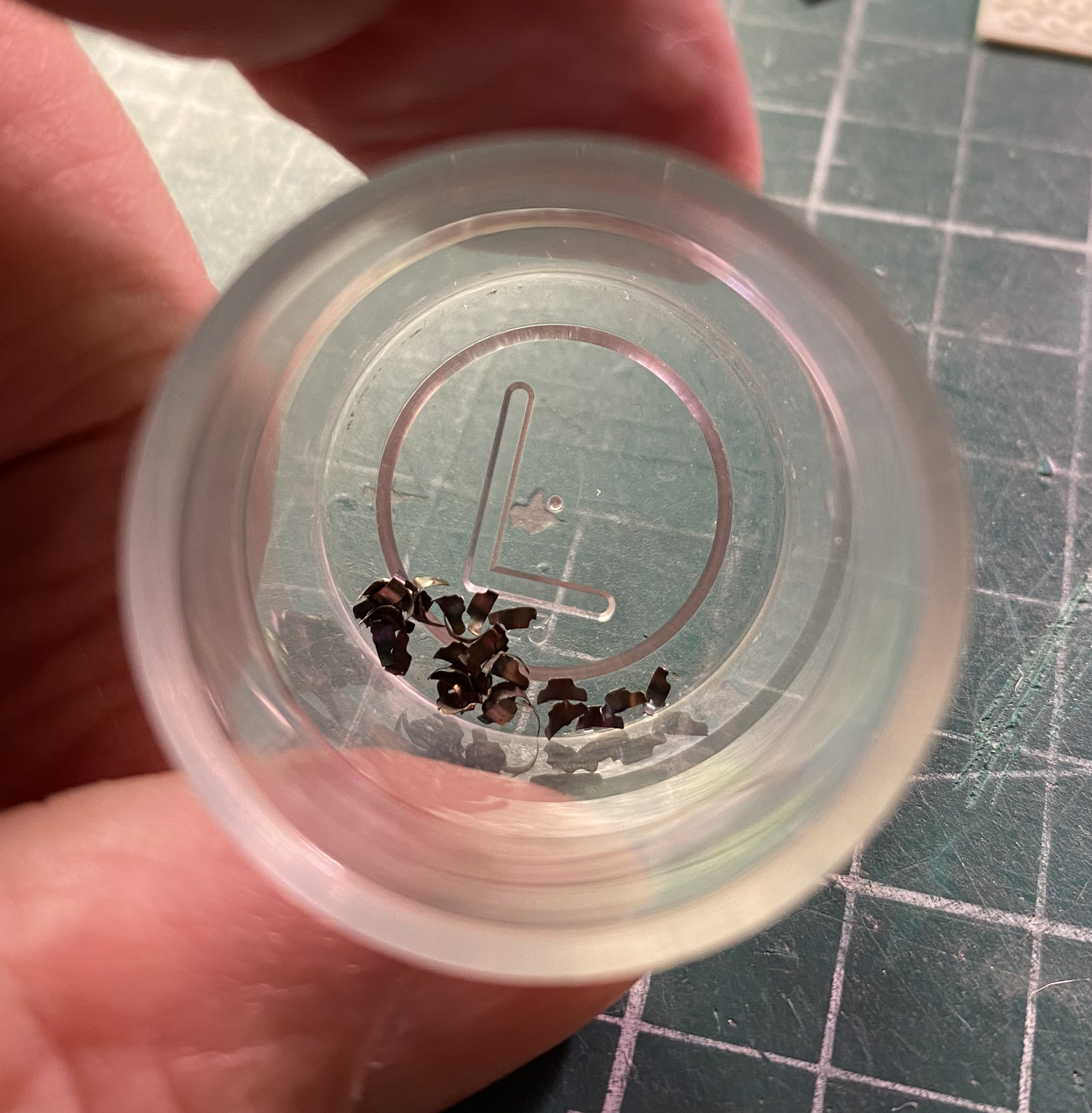
Tedious. VERY TEDIOUS. After two hours I’d only glued three of the guides in place and they absolutely and totally sucked. Useless. I snapped the three off (that part was easy) and stuck them into the container. They now reside in my spares stock for perhaps future use.
::spits::
Since I’d already cleaned up the resin parts of the ammunition racks, it was time to glue them to the sponsons. This is another instance where having four hands would have been useful. It took me some skull sweat to figure out how to even start, and I started with the inside wall of the bin:
I had three plates that all had to line up since I intend on using Tamiya’s ammo set. So I used three pieces of it as alignment dowels:

Worked well, mostly. If you look at the back plate (where the pointy ends of the ammunition points to), you’ll see that the back plate doesn’t come down far enough. I used a small piece of .020″ (.205mm) to bridge the gap:
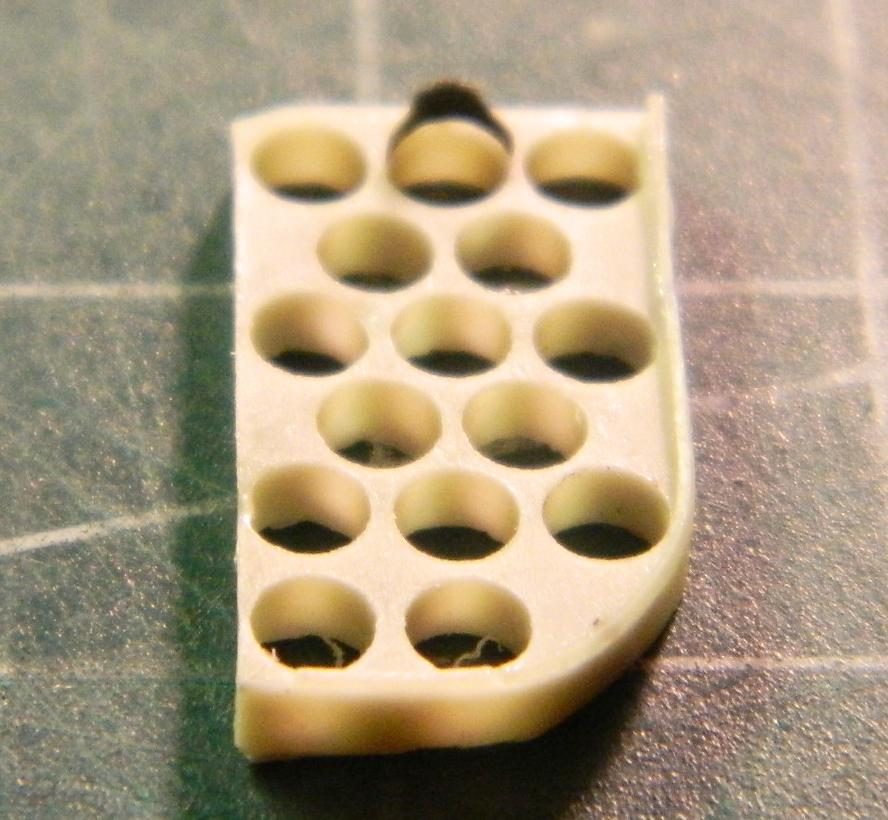
Then I had to do that again for the forward ammo rack (which has a structural support for the weight of the turret above it…it’s the dark gray square part):

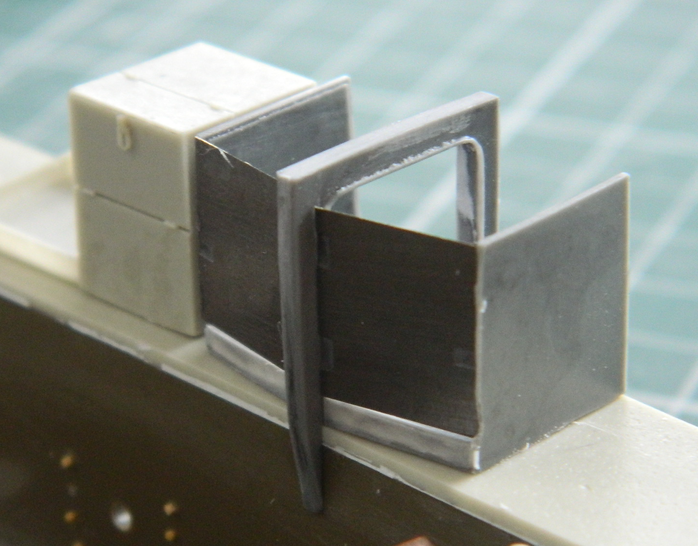
These parts are also for an ammunition rack. I have to say, though, that this makes less than no sense to me as you’ll see shortly:
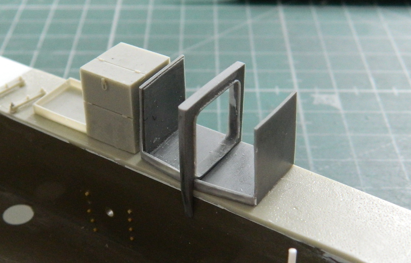
With the doors (though I’ll bet they called them “hatches”) in place, and considering the location of the hinges (the center upright), every time the forward door was opened it would smack the driver in the face. Every time the rear door was opened, it would smack the driver in the back of the head. And this was just opening the doors. Wrestling a 75mm round out of there while the driver was seated would have resulted in someone getting a 75mm suppository:
The rack itself, the thing that’s supposed to hold 75mm shells in place, makes NO sense to me so I’m not adding it and will build this with these DUMBass doors closed.
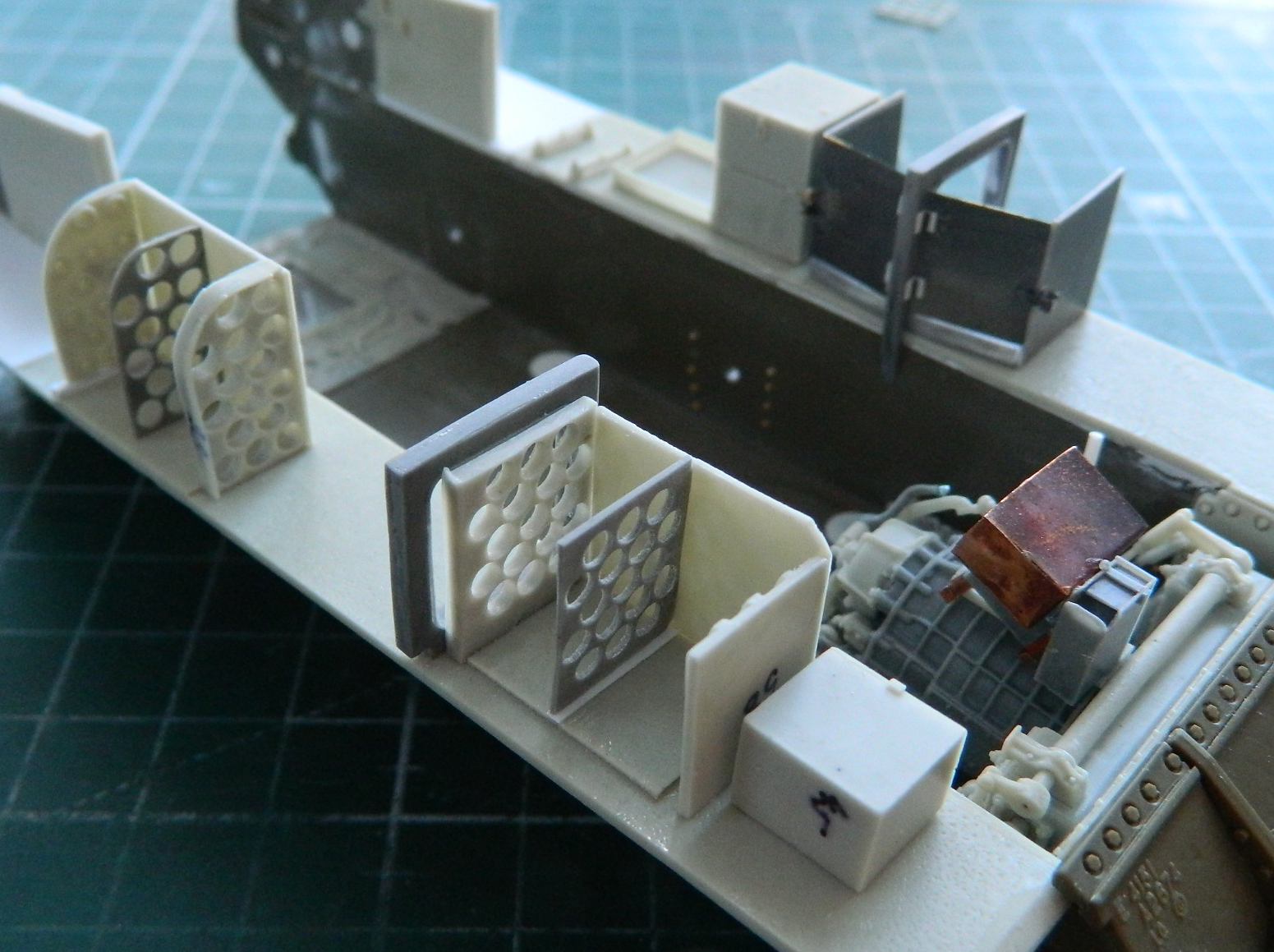
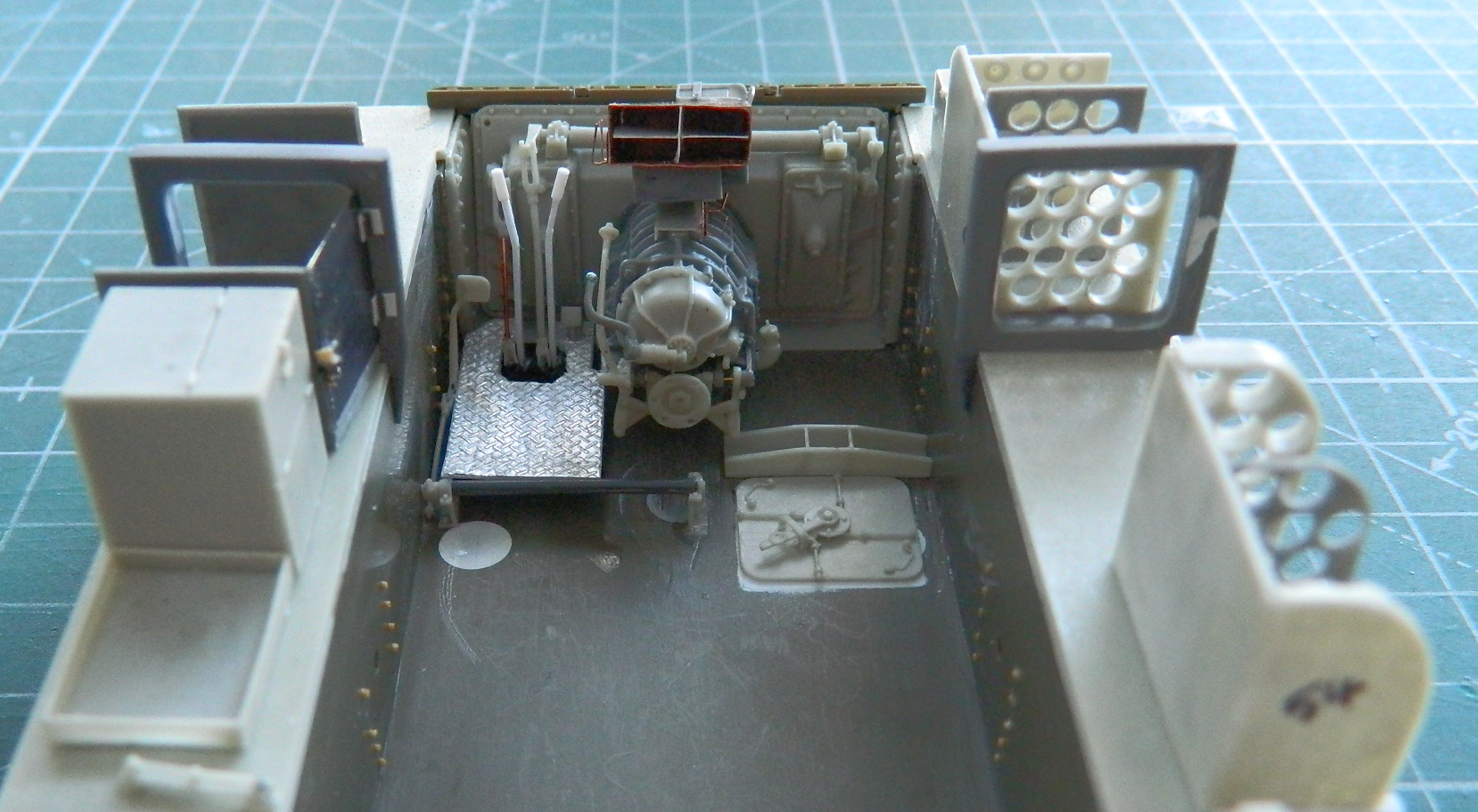
The inside of the rear is now finished:
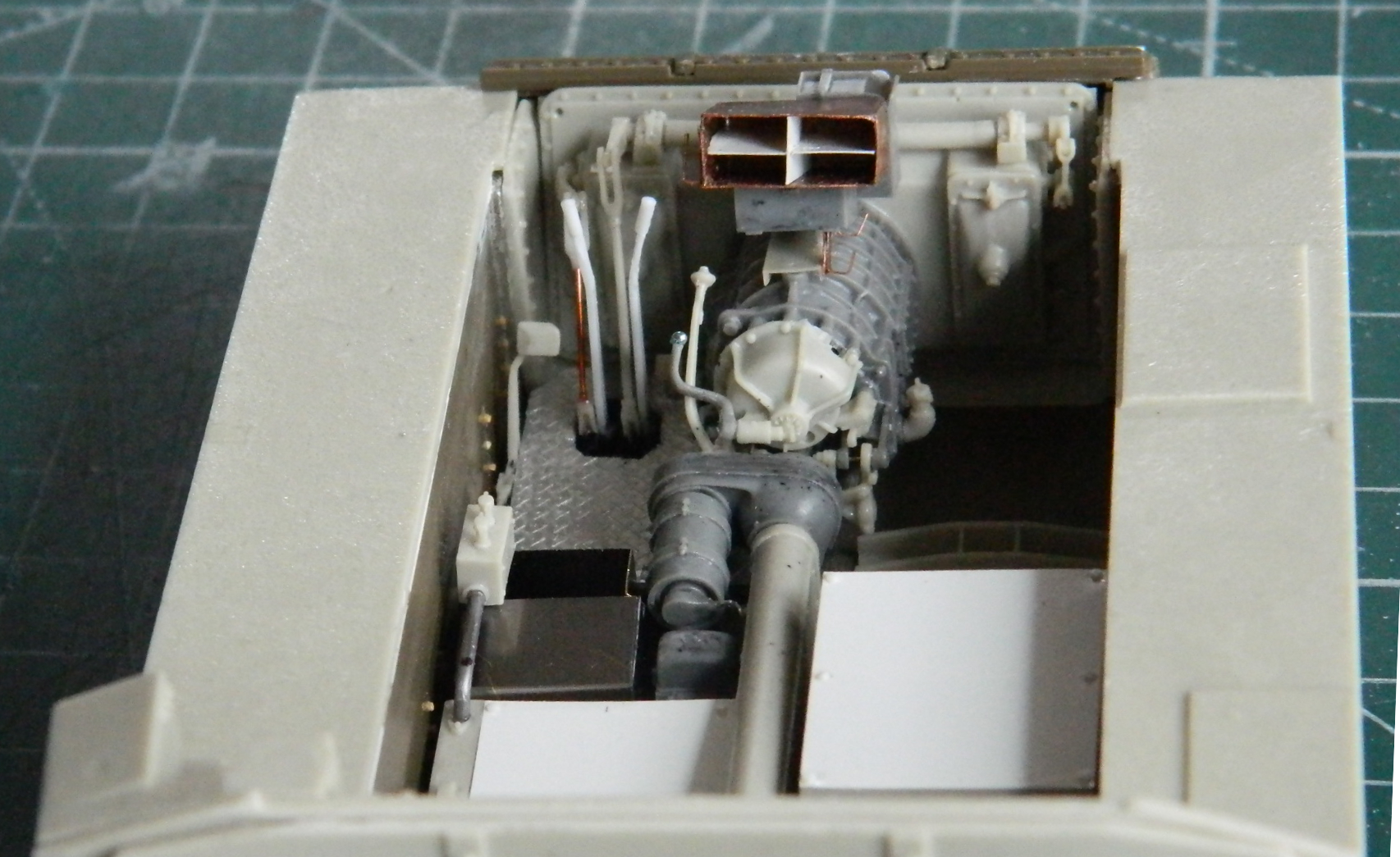
And most of the things that populate the sponsons in place (the instrument panel and auxiliary generator have to be painted before installation):


It’s time to get things ready to paint black. To keep things from being blown off the bench by the airbrush, I used double-sided tape to stick them to a piece of cardboard:
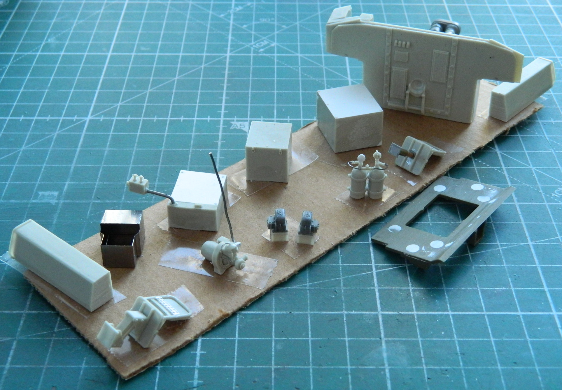

And then I sprayed Tamiya XF-1 Flat Black over everything. While the paint was curing, Panda Plastic’s T48 Rubber Chevron Worn Tracks arrived:

If you’re building something that uses the VVSS suspension of a Sherman, and individual track links are less desirable to you than a digital prostate examination, check out Panda Plastics tracks. I use them whenever I can. End of free endorsement.
Three days later I had 80 links assembled (yes…I’m “supposed to” only need 79 per side):

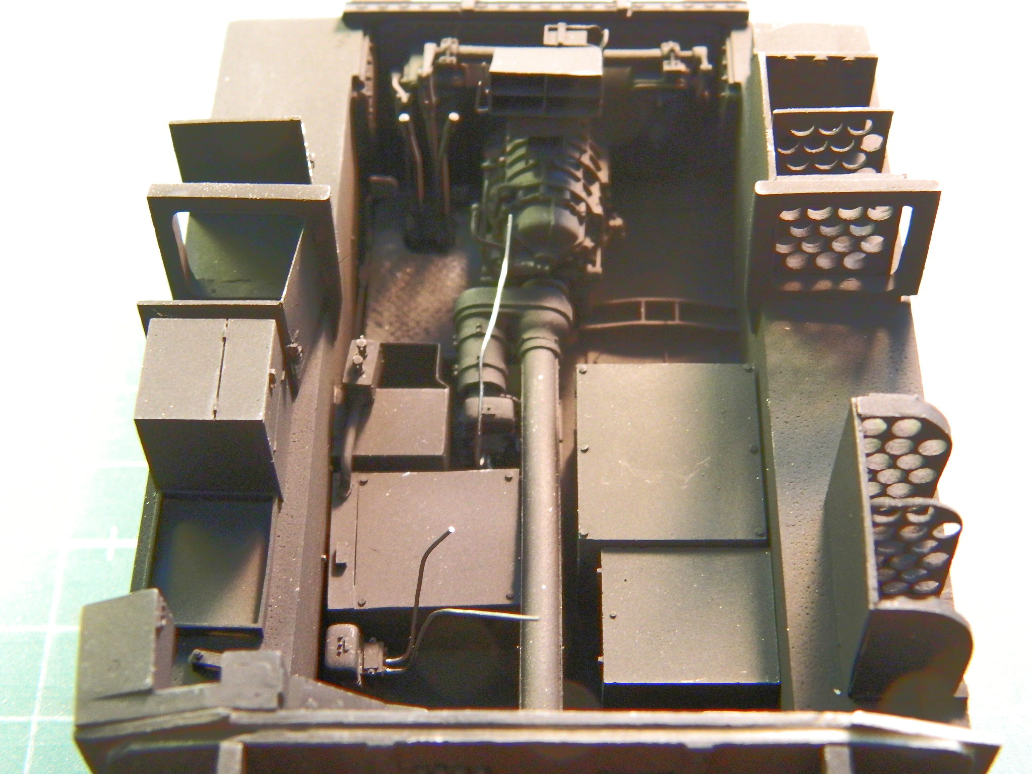
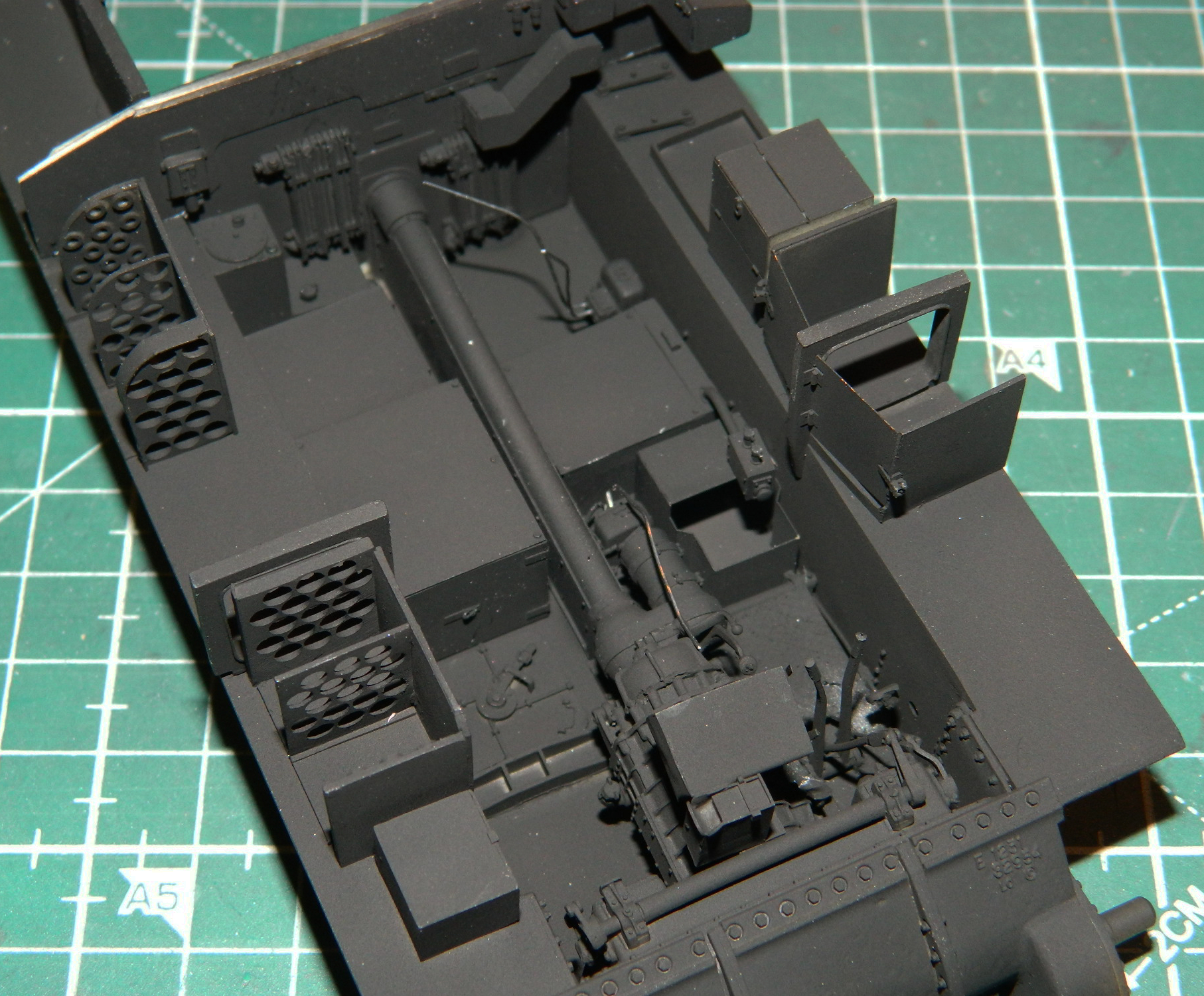
Yeah, so, sorry about these photos. Lousy light today so I used a flash and tried to adjust it in post. I’m not pleased with them but here’s where I am now, everything shadow-coated:

Maybe next month I’ll work on fitting the engine…
