Getting a Better Pump
The vacuum pump I made from PVC pipe and fittings worked okay. Pumping myself into a frenzy only got me slightly over 25″ of vacuum, which was acceptable for my uses. However, it was the “frenzy” part of using it that got to be expensive. My back is made from glass rods and broken promises and it does not respond well to anything that has “frenzy” attached to it.
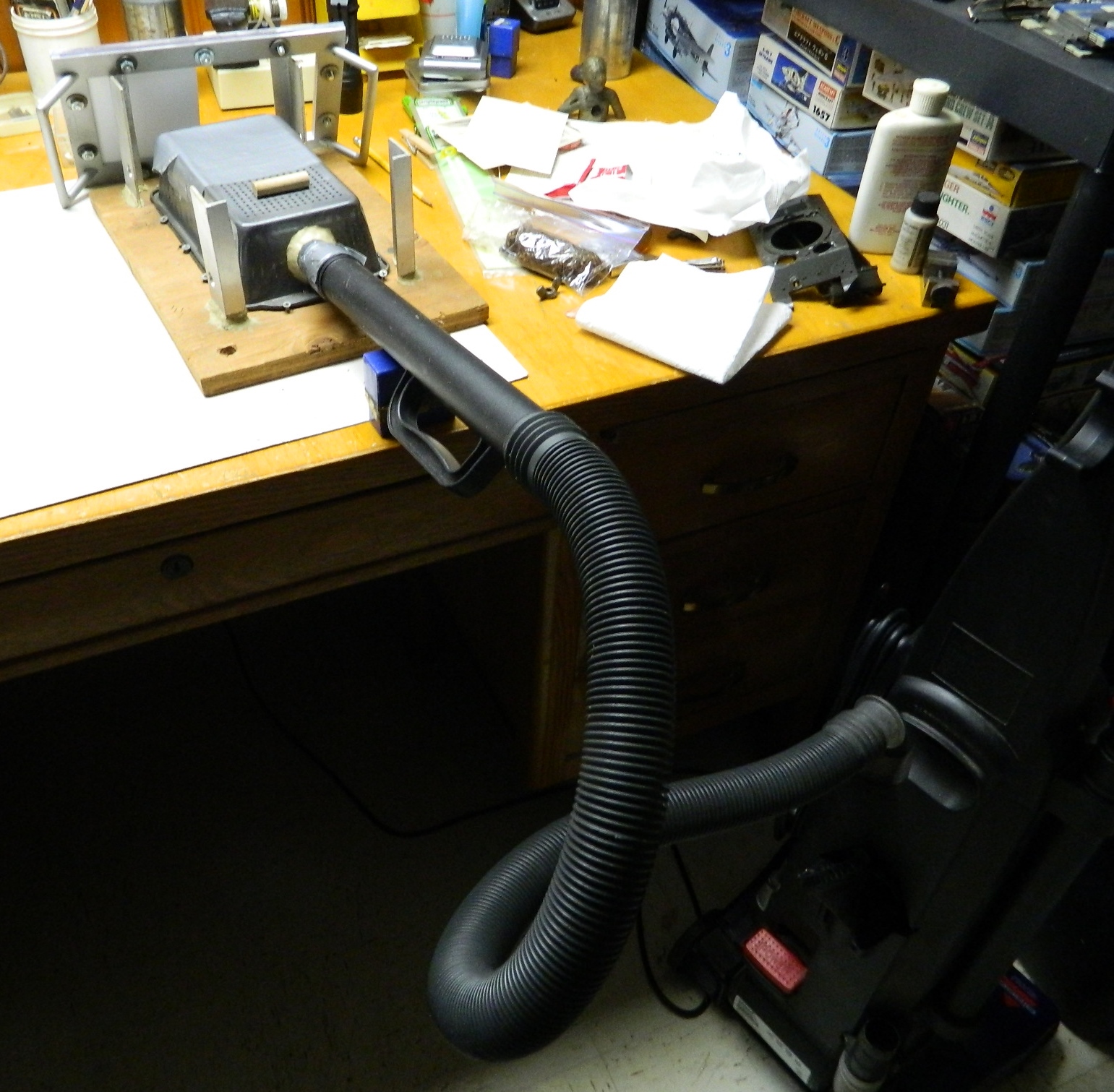
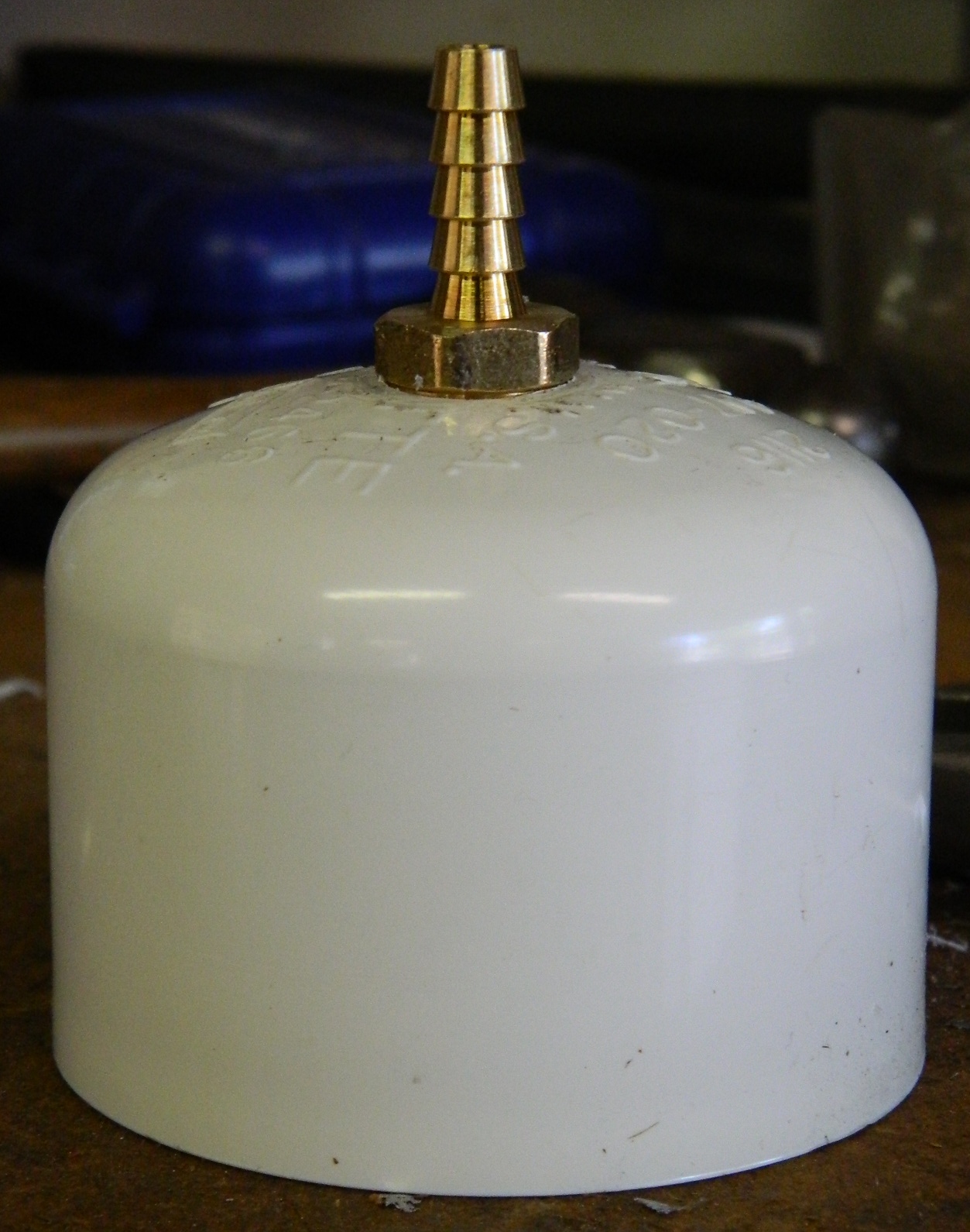
While I was researching vacuum pumps, I ran across a vacuum pump that is intended to be used to evacuate automotive air conditioning systems. And then I found a YouTube video where someone had used that type of pump for purposes of degassing. Harbor Freight has it; their item number is 98076 at $100. It’s a 2.5 CFM (cubic feet/minute) pump with a 1/6 hp 110V motor. The only modification I needed to make was to unscrew the fitting for a/c systems and screw in a 1/4″ barb for the vacuum hose:

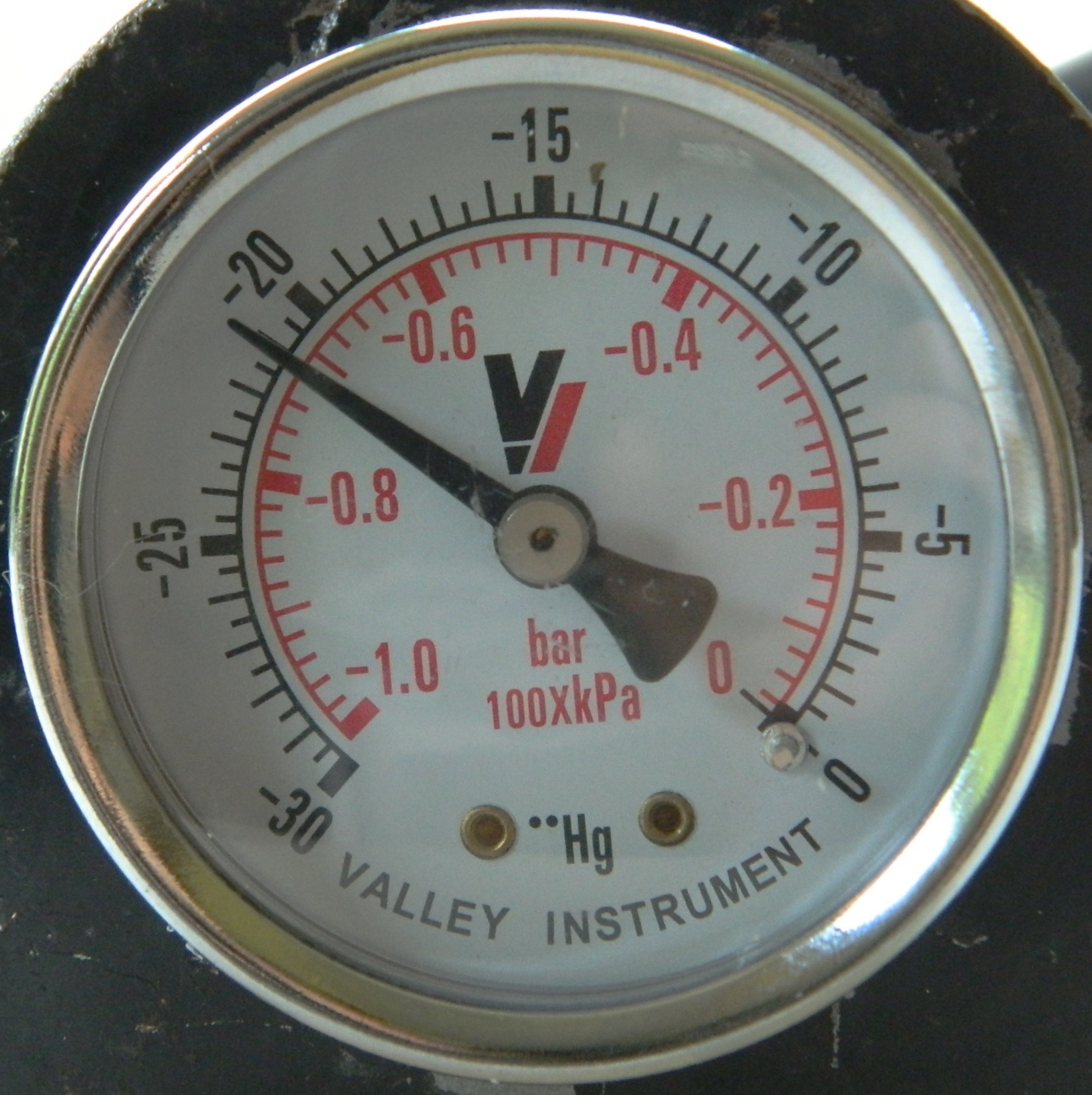
It’s a LOT easier on my back to flick a switch! It takes very little time to generate 29.5″ of vacuum and that makes a noticeable difference. If you’re going to be doing little degassing then the PVC manual pump would probably suffice. If you’re going to be doing more than a little degassing, I recommend getting something like this.
Making the Vacuum Chamber
Now that I can generate vacuum, I need a place to generate a vacuum in and that’s a vacuum chamber.
Commercial/scientific vacuum chambers are expensive…like sometimes into the thousands of dollars expensive. Though one would be nice to have, I have neither the money nor the necessity for that level of chamber. What I need is something vacuum tight that can hold that vacuum long enough to provide utility.
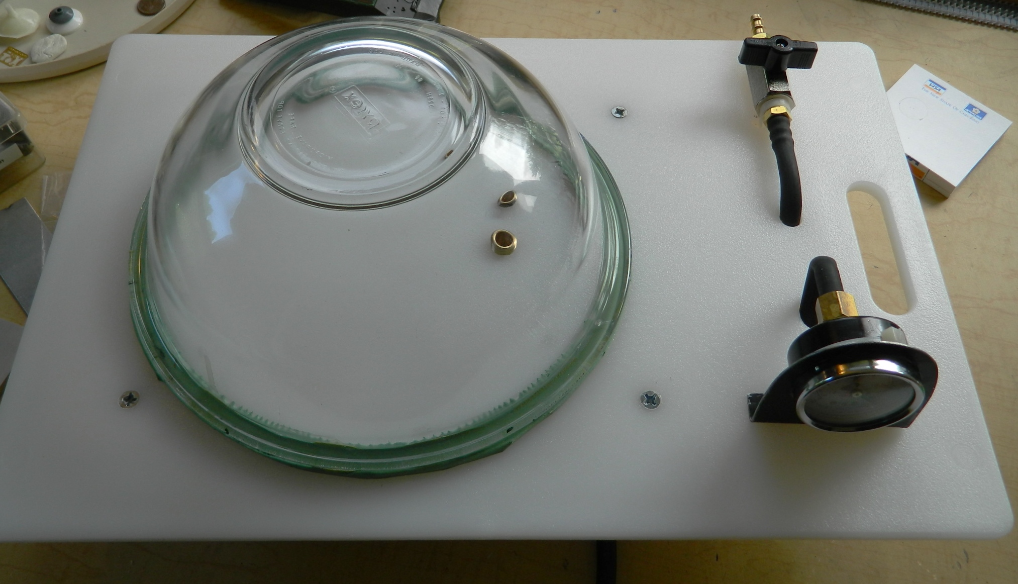
I’ll be using an 8 1/2″ diameter Pyrex bowl, an acrylic chopping board, and some other bits to hang it all together. The bowl will need to seal against the acrylic board and to do that it will need a gasket. I have an old backpacker’s sleeping pad that I use whenever I need closed-cell foam and that’s what will make my gasket. The bowl itself has a 3/8″ lip around the edge which will make attaching the gasket easier.
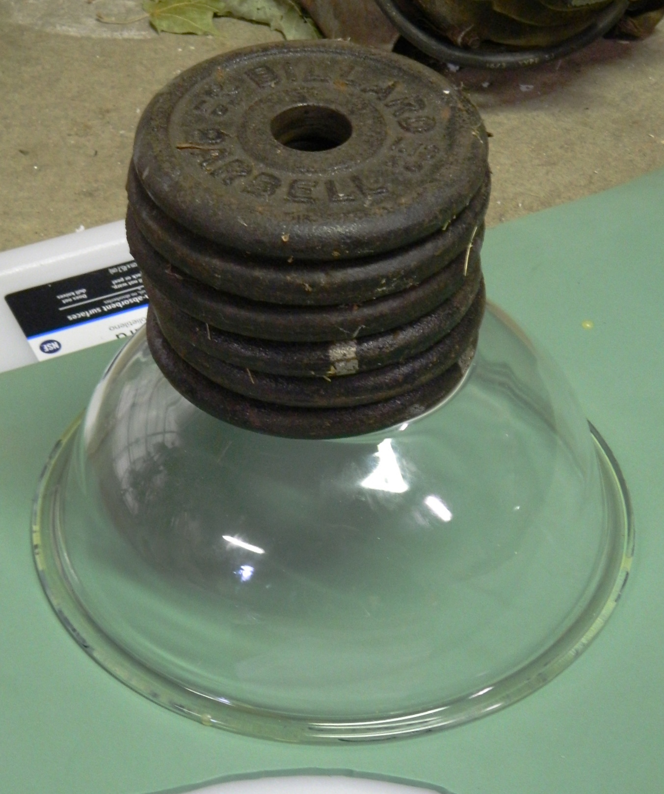
I used Contact Cement on the lip, turned the bowl over and placed it on the foam, then I added a few pounds of weight to the bowl to ensure a good seal and bond:
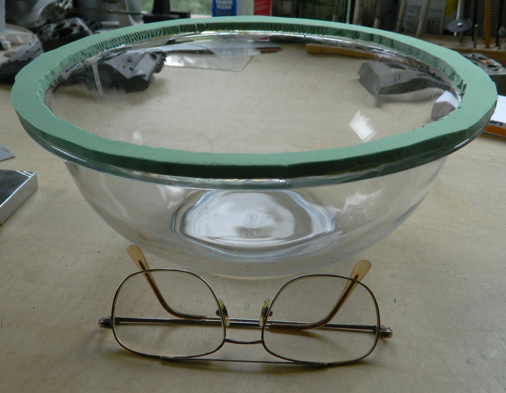
I let it set up overnight, then cut the foam away, leaving a gasket around the edge of the bowl:
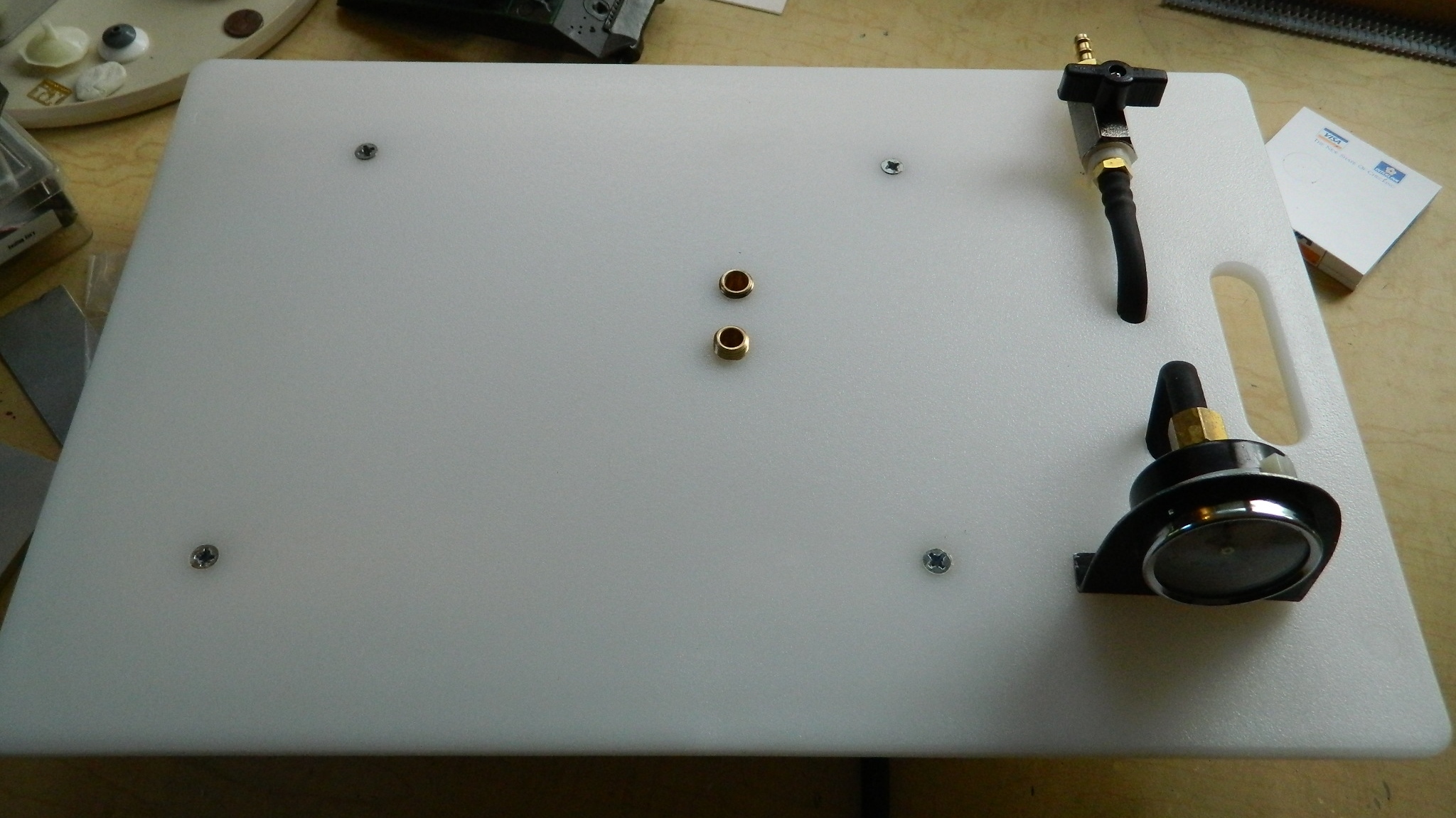
Because each component of this chamber could leak, I decided to test each component as I added it for vacuum tightness to make fixing what leaked easier. As with the V1.0 version of the pump, there was a V1.0 version of the chamber (which didn’t work; don’t use plywood for the base). I’d already checked the gauge and release valve for tightness, so each time I drilled a hole and screw a fitting in, I tested it:
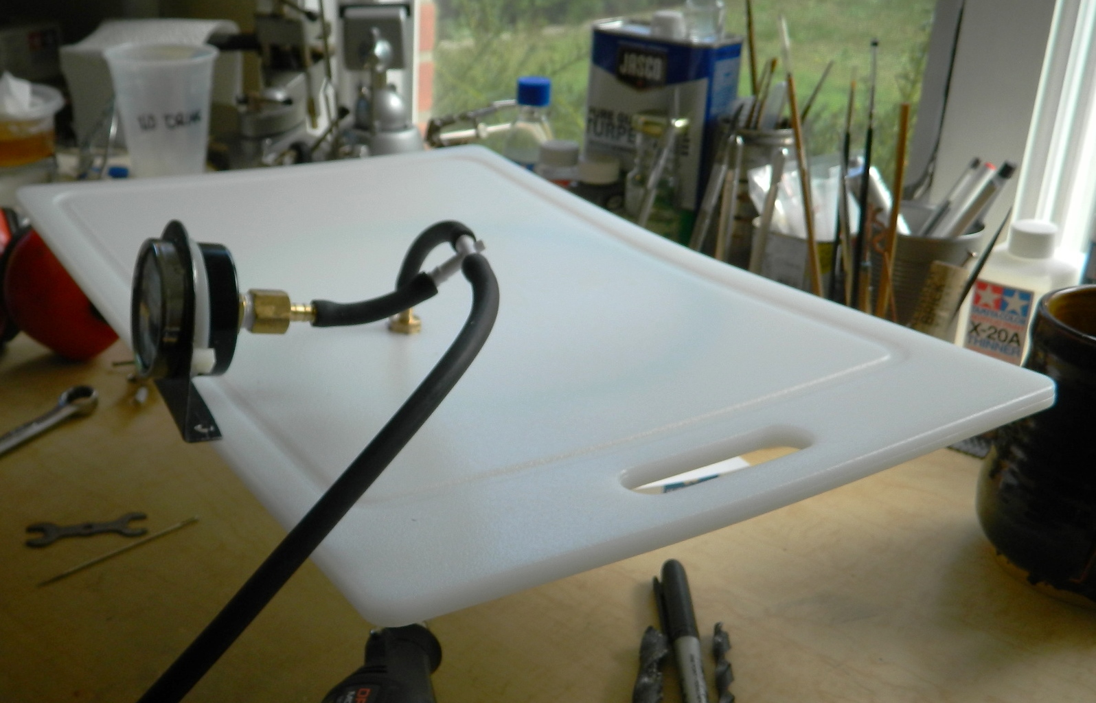
Yes, the acrylic board is a bit thin and under the pressure it bent. I’ll fix this later by adding stiffening legs underneath it to minimize the deflection.
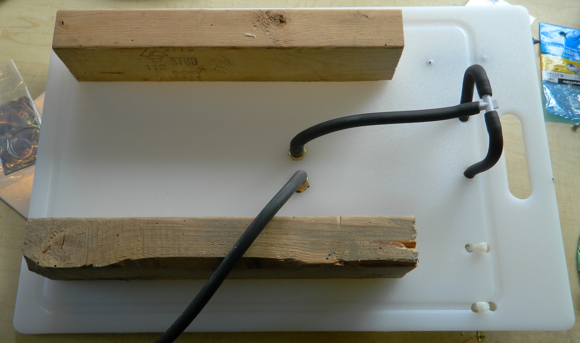
It’s really a simple thing to build and it didn’t take long. This is the (mostly) completed vacuum chamber (because there are always tweaks, y’know). As you can see, I used some scrap wood to make the stiffening legs and they work fairly well. There is still deformation but it’s well within tolerances:

I attached the release valve using cable ties:

Because the surface of the acrylic board has a pebbled texture, I was curious to see if the foam gasket would seal well enough and it does.
During use, I’ve discovered that it’s VERY easy to have the silicone molding rubber overflow the mold boxes. To keep that from happening, I diddle with the release valve, increasing the vacuum, then releasing it when the bubbles threaten to overflow the box until enough of the air has been purged to keep that from happening.
Also be careful of what you’re using as the body of the chamber. You wouldn’t think that atmospheric pressure, 15 lbs. per square inch, would pack so much power…but it does. I haven’t had any problem with using a Pyrex bowl; it’s made of tempered glass and the hemispherical shape distributes the atmospheric pressure evenly. Just be careful AND USE EYE PROTECTION WHENEVER YOU’RE WORKING WITH A VACUUM CHAMBER!!
Making the Pump
I needed something to pump the air out of an enclosed space and, oddly enough, that’s called a pump. Most of this pump is made from PVC pipes and fittings you can get at Lowe’s, Home Depot, etc.
What you’ll need:
2” PVC end cap (bottom of the pump body) (possibly 2 if you can’t find the reducer below, as I couldn’t)
1 ¼“ PVC end cap x 2 (piston)
2” to 3” PVC adapter (base)
3”x4” PVC closet flange (base)
2”OD x 16”L PVC pipe (pump body) (might have to buy 2’)
3”OD PVC pipe (short; base) (might have to buy 2’)
1 ¼“ OD x 20”L PVC pipe (piston shaft) (might have to buy 5’)
1 ½” x 2” PVC Reducer (piston retainer) (if you can’t find one, get another 2″ PVC cap)
¾ x 10” dowel (pump shaft handle; I used oak, but you can use whatever you wish)
PVC primer/PVC cement (two-pack)
¼“ hose threaded fitting, male x 2 (to attach the pump and release valve and vacuum gauge to the vacuum chamber)
¼“ hose threaded fitting, female (to attach the vacuum gauge to a hose)
¼ “ vacuum hose
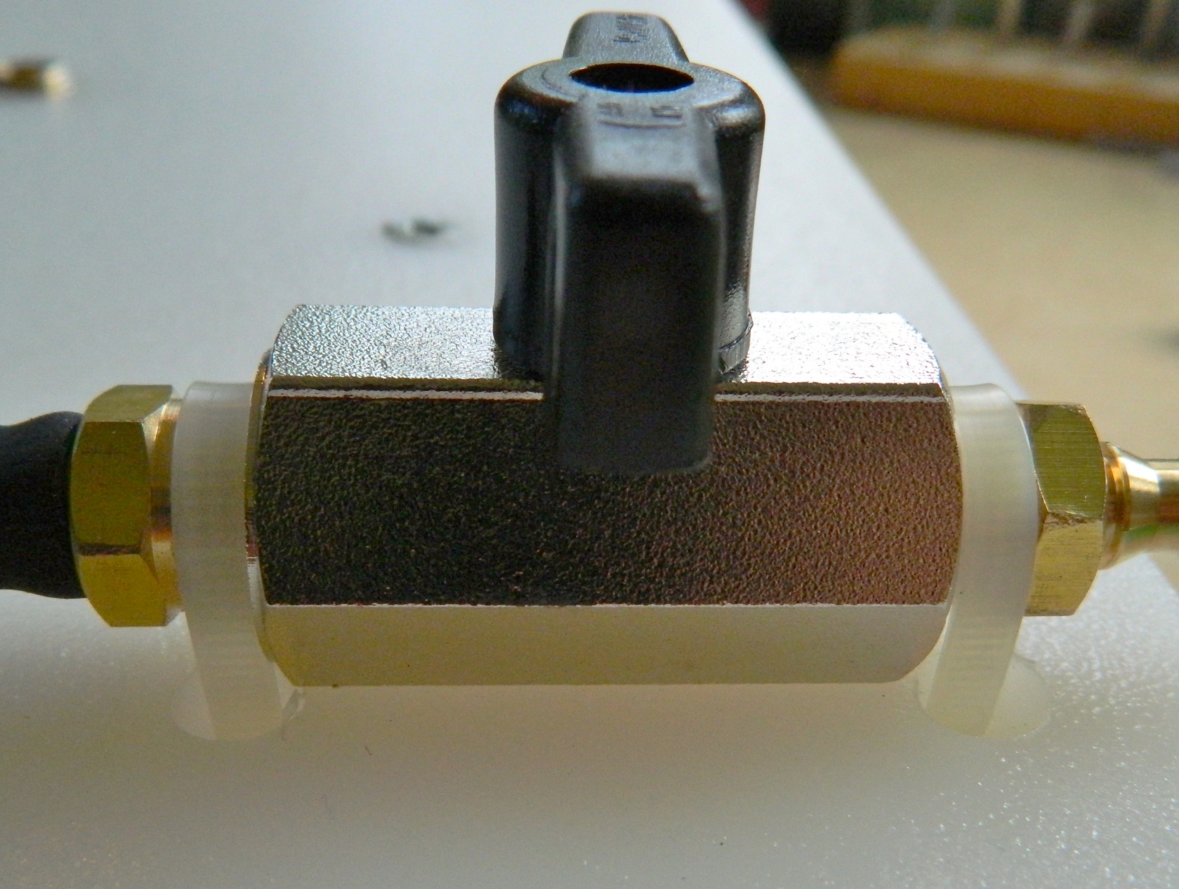
T-fitting (to attach the vacuum gauge and release valve)
Vacuum gauge
Valve (to release the vacuum)
1/8” sheet rubber x 4 (Plumb Pak 6-in Rubber Washer, found in the plumbing section)
1/16” sheet rubber (Plumb Pak 6-in Rubber Washer, found in the plumbing section)
So that confusion is minimized, I use the following terms to describe the various parts:
Pump base (closet flange, 3″-2″ reducer, 4″ piece of 3″ pipe)
Pump body (the part that holds the piston and attaches to the pump base)
Piston (the major moving part that rides up and down in the pump body to evacuate the air from the chamber)
Before you start cutting, drilling and gluing, a general note regarding PVC pipe and fittings. These things fit TIGHTLY. Having pipes seated all the way into the pipe is A Good Thing, so when I was gluing this all together, I hammered the pipe all the way into the pipe. When gluing, use adhesives specifically for PVC. It’s a two-part step. The first part is to prep the surface with the primer and the second step is to use the adhesive. The adhesive should not be a gel but rather it should be a thick liquid. Also, use in well-ventilated areas! This stuff is strong and is not good for you to inhale.
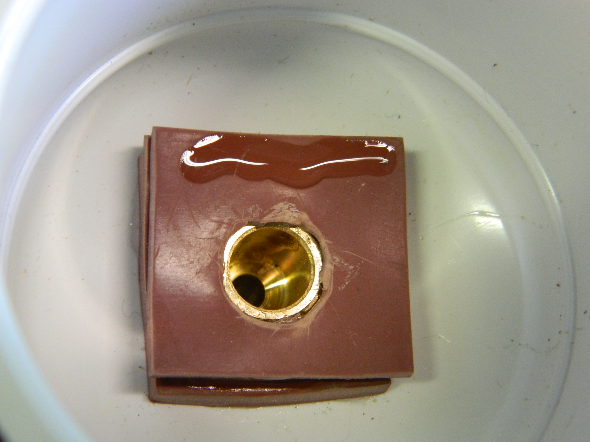
I started by drilling a 2″ end cap and seating a hose fitting to it:
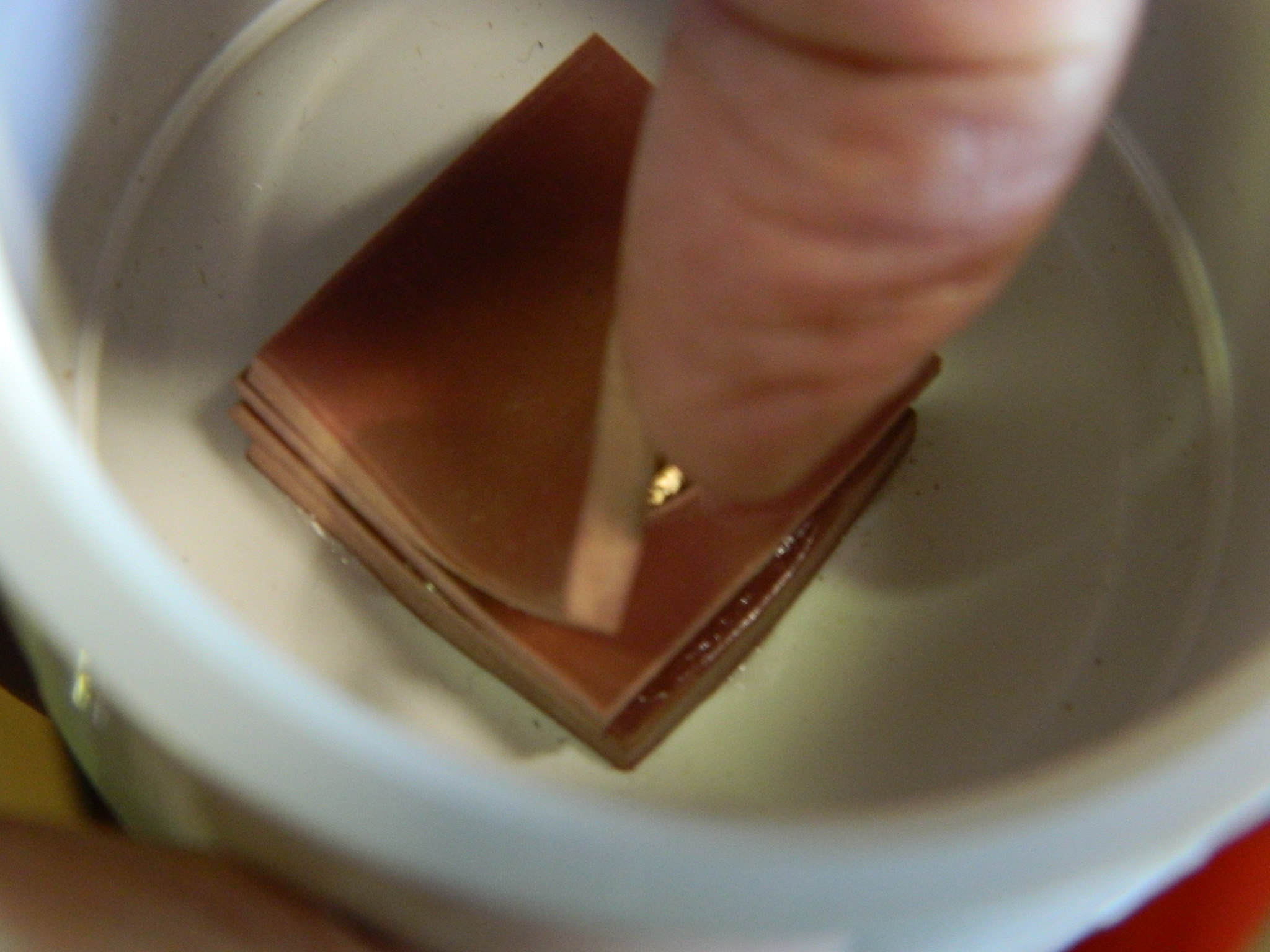
I made a flap valve using a few pieces of 1″x1″ 1/8″ rubber sheet by drilling out the centers. I used enough pieces so that the end of the brass fitting sits below the stack of rubber. Then I glued a 1″x1″ piece of 1/16″ rubber along one side only. This is the valve that closes under positive pressure to void the air pulled from the vacuum chamber to the outside:

I had a massive problem with the V1.0 pump. The body of the pump didn’t go all the way into the end cap with the valve and fitting. The first time I pushed the piston all the way in, the O-ring passed the end of the pipe…where is stuck. Solidly stuck. Which is to say, wouldn’t sodding come out. After two hours of very colorful invective (using some words in combinations that I hadn’t used in decades when I had to start an English motorcycle in the rain), I did manage to extract it (drilled the body of the piston crosswise, put a 1/2″ stainless steel rod through, braced the edge of the cap in a vise, and HAMMERED THE SNOT out of it with an engineer’s hammer, which finally extracted the rod, but required sufficient force to bend the stainless steel rod). I needed to figure out a way that this would never, ever, happen again…
I took a short section of the 1 ¼“ pipe and glued it into the 2″ cap around the flap valve. I cut the corners off the flap valve so there would be no interference, and superglued that ring in. I measured (a lot) to be certain that it was physically impossible for the O-ring to ever pass the end of the pump body again. EVER:

Then I drilled near the bottom of this cap/valve/fitting assembly and made the valve that closes under negative pressure to keep the outside air from getting in and then glued the completed part to the 2″x16″ PVC pipe that constitutes the pump body. Make certain the pipe bottoms into the cap all the way:


A 1 ¼“ cap now needs to have a groove cut into it to seat the O-ring. With the V1.0 pump I didn’t cut this groove deep enough and on the first pump the O-ring popped out. I suggest that you cut the groove as deep as half the diameter of the O-ring’s thickness. The reason why the first groove was so shallow was because I was concerned that I would cut too deeply and the end of the cap would come off. I figured out a way around that.
Cut an inch from the 1 ¼“ tubing. You’ll need to sand/file the outside surface of it so that it fits easily (yet snugly) all the way into the cap and glue it in. This will give you enough thickness to cut the groove deeply enough:

Then it’s a matter of cutting the groove. Be patient and check your depth relatively frequently. Now that you have backed up the inside of the area you’re cutting the groove into, you don’t have to worry about cutting too deeply, but it does take some time to cut this groove and I didn’t want to cut any further than I needed to. And since I have a lathe, I roughed in the groove using a cutter and then finished its round shape with a rat-tail file (I actually went deeper than the photo on the right shows):


With the O-ring in place, this is the part that seals the piston inside the body of the pump and every time you pull up on the piston, it pulls air out of the vacuum chamber creating a vacuum. The end cap is glued onto the 1 ¼“ pipe and forms the business-end of the piston:

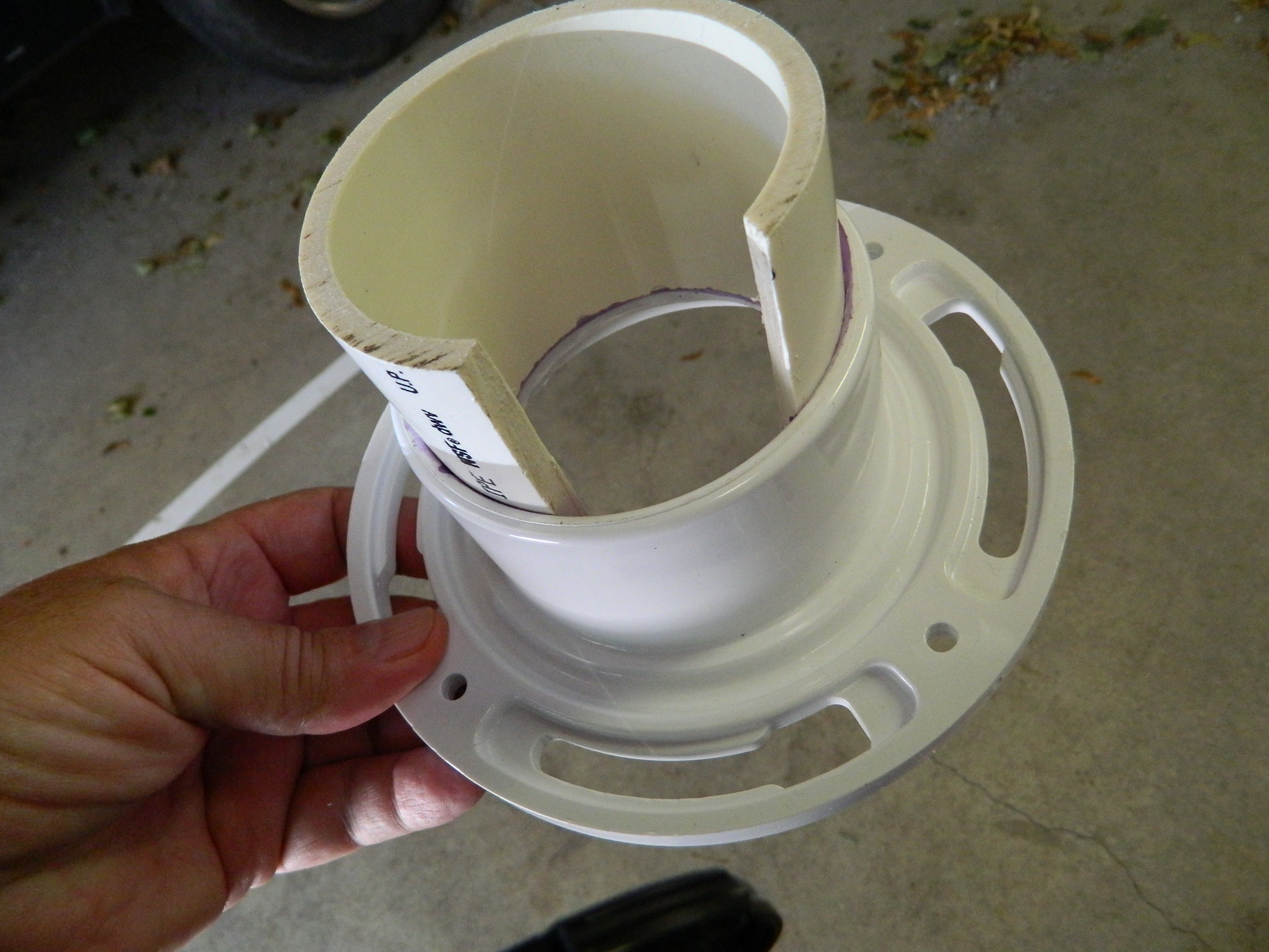
The base of the pump is assembled using the floor flange as the bottom. To that is added a 4″ length of 3″ pipe. But wait…there’s more. The 3″ piece of pipe needs a section cut out of it to allow the outer flap valve to work. Make sure your cut in the side of the 3″ is wide enough to accommodate the width of the outer flap valve. Once you’ve made that cut, the pipe will contract slightly. Reverse the piece you cut out and stuff it back into the opening. This will keep the section of pipe at the proper diameter and allow it to bond with the floor flange when you glue it (you’ll see what I had to do in the Vacuum Chamber section when I didn’t get this step quite correct).
With the reversed piece in place, the 3″ pipe gets glued into the floor flange. Let this sit for at least an hour (I let it sit for two) so that the parts bond solidly. You’re going to be standing on this and yanking upward firmly and often:

Reducers have a lip molded inside to keep the smaller pipe from slipping through the reducer. Since you’ll want the smaller pipe to slip through the reducer, that lip needs to be ground away. (If you have a Dremel or the like, that cuts down on the time this step takes.) Once you have that lip gone, you’ll need to open the inside diameter of the 2″ area of the reducer so that the body of the pump, a 2″ pipe, will slide through there. You want this to be snug but not immovable:

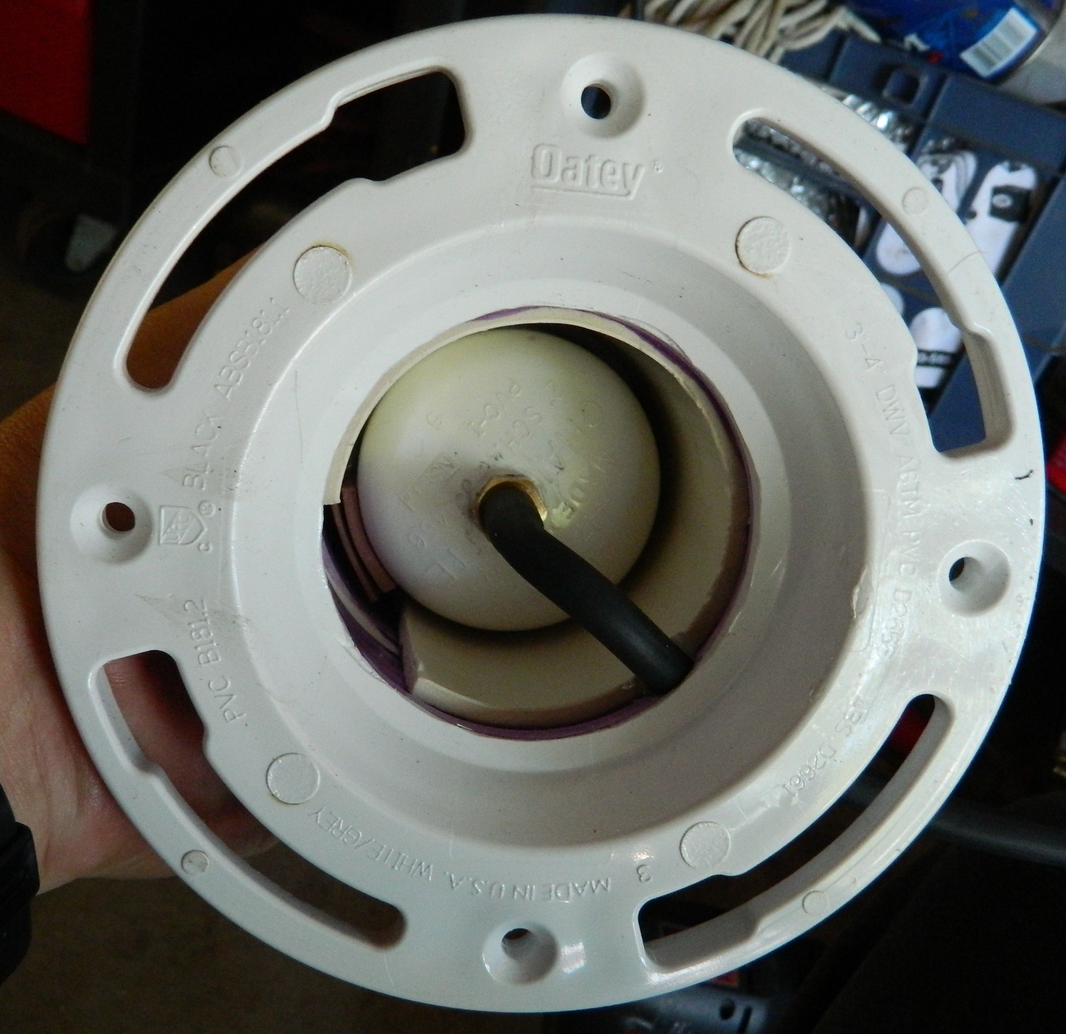
Snap the cut piece out of the pipe and then glue the modified reducer over it and drill a hole large enough for the vacuum tubing to fit through without pinching:

Now the body of the pump is fed up through the bottom of the base and glued, pushing the body in until the lip of the cap stops at the bottom edge of the reducer. Make sure that the flap valve and the cutout section of 3″ pipe align, otherwise the flap valve won’t work:
Time to insert the piston into the body. With the O-ring in place, THIS IS A TIGHT DAMNED FIT! The only way I was able to get the piston to go in was to chamfer the top of the body of the pump. I used a half-round file and sandpaper until the outer edge was about half the original thickness:

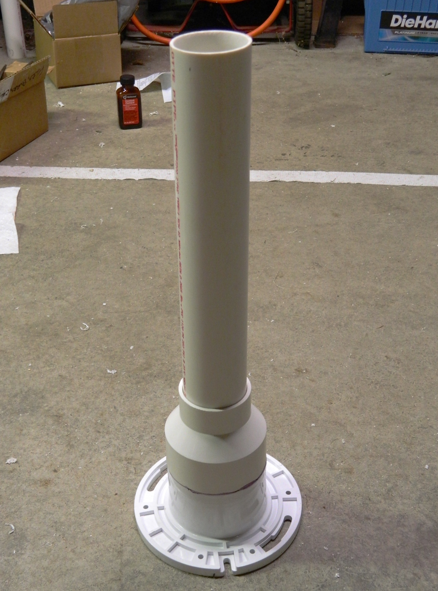
By now you should be here:
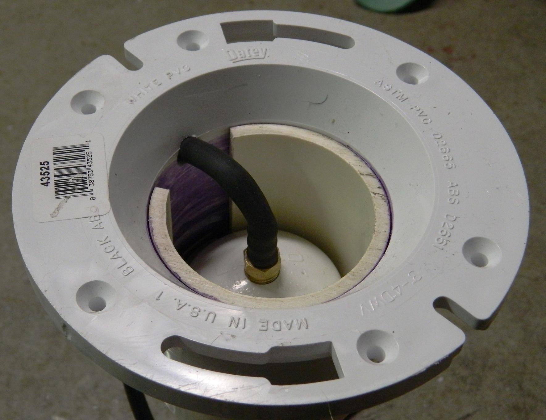
Feed the vacuum tubing through the hole and attach it to the fitting. Subsequent use of this pump showed me that the tubing doesn’t fit quite tightly enough so I used a cable tie pulled TIGHT to seal the tubing to the fitting:
Time to install the piston. Use grease to help the seal, extend the life of the O-ring, and to get the TIGHT DAMNED FIT to…well…fit:


The retainer is needed to keep the piston in the pump because you will be pumping vigorously to build up vacuum. The video shows a reducer that I wasn’t able to locate locally. My way around that was to take the other 2″ cap, chuck it into my lathe, and cut enough away so that the body of the piston would slide freely within it (you can also mark the hole, start the hole with a bit, and either file or use a Dremel to get the diameter to where you want it):


And because I clearly remember how much sodding, freaking, GOD DAMNED FUN it was when the O-ring slipped past the body of the pump, I made sure that the O-ring would not slip past the body of the pump at the top, either:
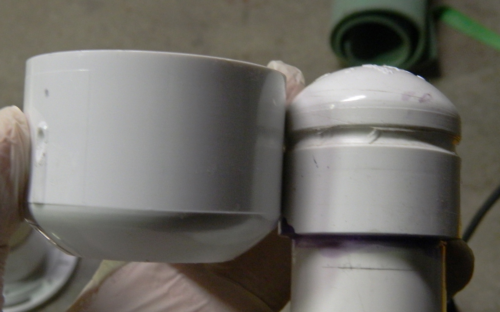
So, with the piston inside the pump body, slide your reducer over the body of the piston. Again, because these fittings fit TIGHTLY, I sanded the inside of the retainer (a lot) so it would fit easily over the end of the pump body and come off just as easily (eventually the O-ring will wear out and need replacing). To be certain that the O-ring would stay inside the pump body, I held the retainer in place with my hand and pulled (gently) up until the piston would go no further. Satisfied that all worked as intended, I glued the last 1 ¼“ cap in place on the end of the piston. I used self-tapping sheet metal screws to hold the retainer in place securely yet not intrude into the pump body and interfere with the piston:

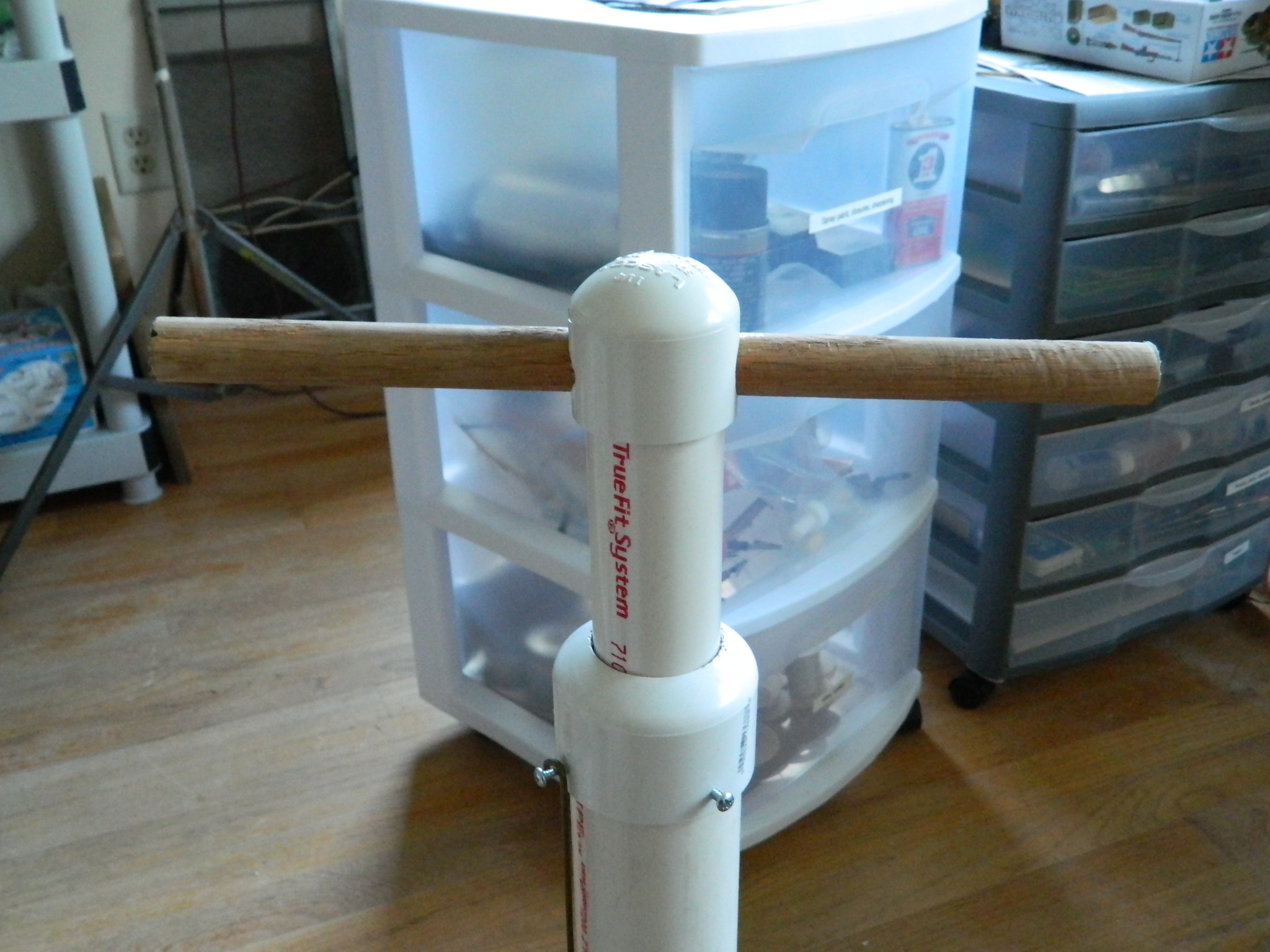
All that remains now is to drill out the top of the piston and insert the 10″ long, 3/4″ diameter, dowel to use as my handle:
Next step, build a vacuum chamber!
Subsequent Edit:
In using the chamber, I found a couple of major problems to address.
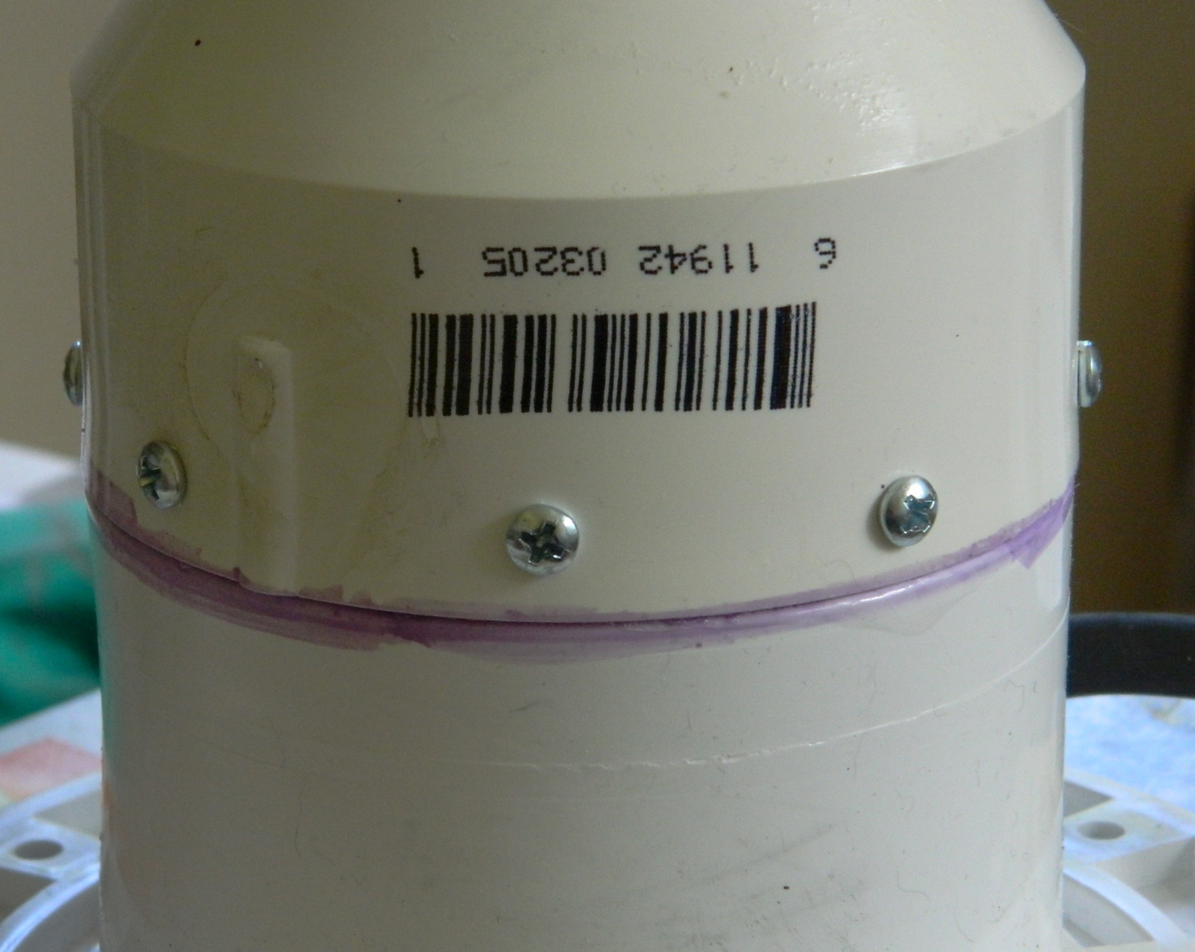
During the construction of the pump, I wasn’t entirely sure that the 3″ section of pipe that connected the flange to the reducer had bonded properly and it turned on it hadn’t. Though the 3″ section bonded very well to the flange, only half of it bonded to the reducer and that snapped free. It doesn’t affect the pump’s ability to create suction, but it does compromise its strength. So I used screws to attach the loose section of pipe to the reducer:
I’ve used the pump a number of times since its construction (and fix) and it’s holding up well.
Another thing I noticed during its first use is that the vacuum bleeds off over time. It takes just under two minutes to go from about 27″ of vacuum to 0″. In using it, I discovered that 15″ of vacuum is about the minimum I want to work with and that equates to a lot of pumping! I diddled about a bit. I added cable ties to seal the hose to the fittings more tightly and that decreased the vacuum bleed off a little. I still don’t know why I did this, but at one point I held the piston up (because vacuum with this pump is created on the up-stroke; it looks like a plastic bicycle pump but operates in the reverse in all ways). I noticed that this slowed the vacuum bleed off substantially. So I drilled a hole across the body of the piston and use a coat hanger to hold the pump up:

Okay…it does work. The emphasis should be on WORK. It takes A LOT of work to generate about 23-25″ of vacuum (the more vacuum generated, the better degassing works). Yes…that’s enough vacuum but it’s TOO MUCH WORK to keep the vacuum.
I needed a better pump.
Degassing – What Is It and Why Do I Need It?
“Degassing” is the term used to remove bubbles from a solution (as in a mixture, not what you need to solve a problem). It’s necessary when using a two-part compound that has to be mixed because not only are the two parts mixed together, so are air bubbles Those air bubbles can and will show up in the least appreciated places.
One way to get those bubbles out of solution is to expose the mixture to a vacuum, which by definition is a pressure less than atmospheric (getting a hard vacuum is possible, just expensive, and I’m a hobbyist, not a manufacturer). The bubbles, having been formed at normal atmospheric pressure (15 lbs/sq.in, if memory serves), are pulled out of the mixture by the drop in air pressure (partial vacuum) and then pop. To do that, one needs something to create the vacuum (a pump) and some place to contain and maintain the vacuum (a vacuum chamber).
Okay, so that’s what a degassing set up is. So…why would I need one?
Sometimes I have to make a part that doesn’t come with the kit or isn’t commercially available. If I need multiple copies of this part then I need some way to reproduce them, because my skills aren’t up to making two, five, a dozen that are identical. Making a mold and casting the part I make solves that situation. And since both the mold making rubber and resin* I’m using are two-part compounds, being able to get rid of bubbles is necessary.
What the degassing rig is for is to pull air bubbles out of both the mold making rubber and the resin* I pour into the mold.
I went online, googled “vacuum pumps,” and ended up being very glad I’m bald, because my hair would have fallen out at some of the prices I encountered (scientific applications need a harder vacuum than my wallet can provide). While searching (and listening to the delicate patter of hair falling out; I won’t have to trim my nose for a month) I found this little gem:
If you decide to build this pump, be aware that there are a few things that can turn and bite you during its construction that aren’t covered in the video. I’ve tried to cover them in the section on vacuum pumps but if you run into problems building one, feel free to contact me. I might be able to help.
*Some resins don’t respond well to degassing; certainly the one I’m using presently doesn’t. When exposed to vacuum the resin froths up. VERY messy. When poured into a mold and degassed, the frothing resumes and actually makes more bubbles not less. I’ve no idea why this is (I’m not a chemist). If the resin you’re using reacts the same way, try pressure casting.
Go here to find out more about pressure casting: Pressure Casting
(Vacuum Molder
When getting into modeling a bit deeper than Out Of Box (OOB), having the ability to make your own parts is quite handy.
An example is the canopy on a 1/48 scale (or any scale, really) aircraft. Sure, the kit part is clear, but if you measure its thickness and convert that to scale dimensions, you’ll realize that the real canopy isn’t six inches thick. Light does “interesting” things when it has to work through thick sections of plastic, and unless you replace that kit part with something closer to scale thickness, it’s going to look like what it is. A small plastic part. That’s when being able to vacu-form scale parts comes in handy.
I got the basic plans from FineScale Modeler back in the ’90s. It’s an easy set up to build and isn’t expensive. (I tweaked it a bit because that’s just what I do.)
To make one of these handy gizmos, you’ll need:
A bread pan, 1/4″ graph paper, sharp 3/32″ drill bit, epoxy putty, silicone sealant, plywood, a piece of pvc or plastic tubing about 4-5″ long, 1/2″ to 3/4″ wood screws, and something to make a split frame with (I used 3/16″ aluminum sheet), a hot place or access to an electric stove (and an understanding mate if you screw things up and drop molten plastic onto the burner) (or someplace else to sleep for a week or two should understanding not be in plentiful supply)
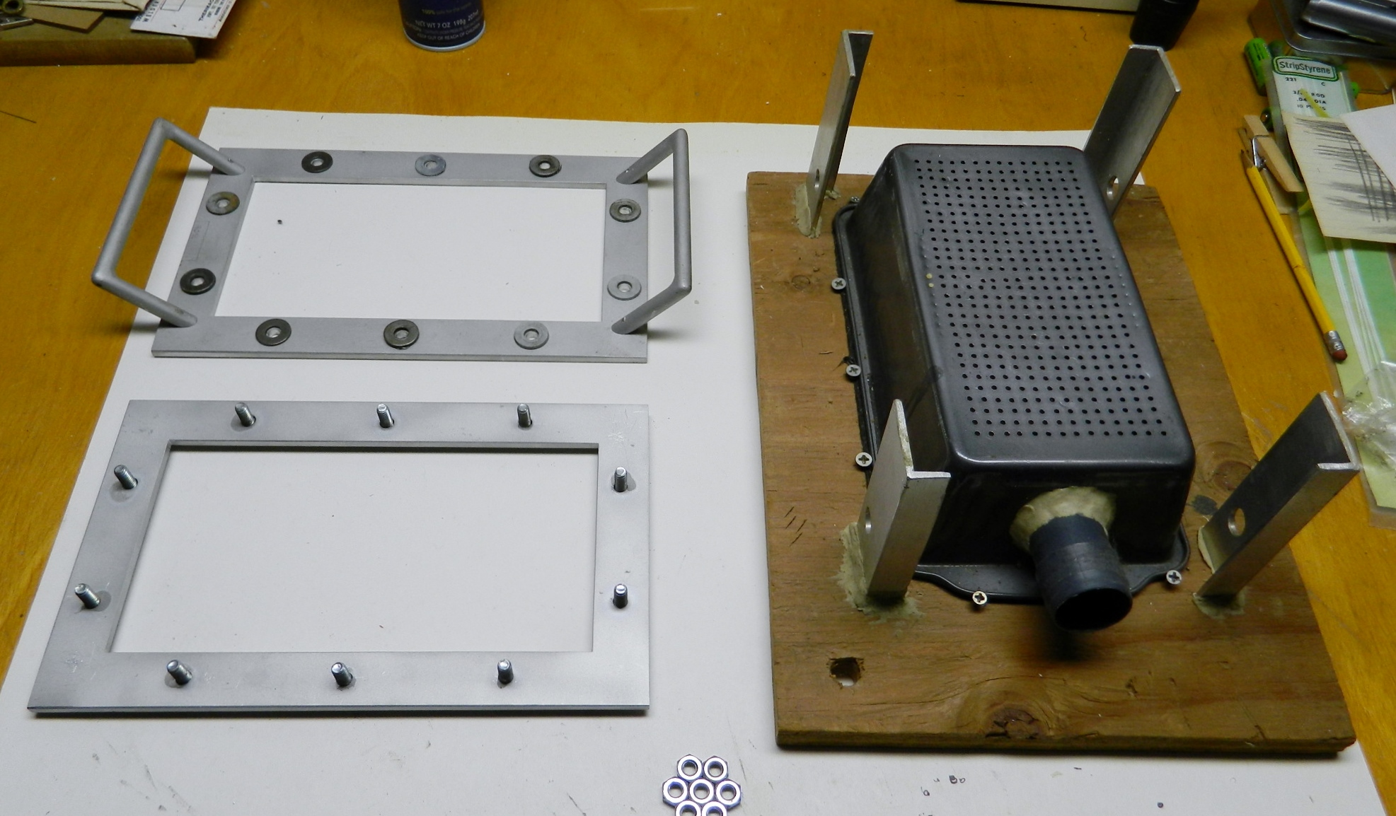
The main part is the plenum. This is the volume that traps the air you’re going to want to suck out. A standard-size, sheet metal bread pan, works great. I strongly suggest you get one that is stamped; it will have rounded edges at the bottom of the pan.
Get some graph 1/4″ paper, where the squares on the paper are a quarter inch square. Turn the pan over so the bottom is up, trim the paper to fit over it, and then tape it down. Take a sharp punch and tap firmly enough to leave a dimple in the metal without deforming it every place the lines intersect.
Use a sharp 3/32″ bit and drill a hole everywhere you made a dimple. Once you’re done, if you end up with what I did, you’re going to need to deburr the surface. For that I used a combination of a fine finishing file and sandpaper. (You don’t want sharp projections to puncture the plastic you’re going to be forming.)
Next you need to cut a hole in one end of the bread pan to attach the pvc or plastic tube to. This is where you’re going to hook up your vacuum cleaner (which is what will draw the plastic down around your form). Once you have the hole cut just large enough for the tube to fit, use the epoxy putty to build a flange on both sides where the tube goes through the hole in the bread pan. Put it aside until the putty has completely cured.
Size your plywood (I used a scrap of 3/4″) large enough to offer a stable base and place your bread pan, upside down, onto the plywood and outline it with a pencil. Run a bead of silicone sealant around the inside perimeter of your outline, settle the bread pan upside down (or with the bottom and all those holes up) and screw it down to the plywood. Let the silicone sealant cure.
The purpose of the frame is to hold sheet styrene (or butyrate) firmly over a heat source (I use an electric hotplate but an electric stove works also). Here’s where I got a little fancy. I had a friend who worked in a machine shop make a frame (two frames, actually) for me from 3/16″ aluminum plate (anything sturdy will do). I sized the inner opening to be just slightly larger than the bottom of the bread pan and the width of the frame to be an inch. I used bolts and wingnuts to hold the two frames together (once all the holes were drilled, obviously, I used superglue to hold the bolts in place), and I guess he was having a boring day at work because he also made me two nice handles for the frame (comes in handy when protecting the delicate fingers from holding this over heat).
Because I’m clumsy, I later added the aluminum L-stock to guide the frame to a centered landing on the platen (bottom of the bread pan with all those holes).
Place your form of what you want to replicate onto the platen. It can be anything of the desired shape that you can pull the plastic down over, things like canopies, body panels, etc. Anything you need a thinner piece of. I’ve found that gluing the form onto a pedestal and getting the bottom of your form off the platen makes life SO much easier! I use a drop of superglue to hold the pedestal to the platen (if you don’t leave it there overnight, it will snap right off).
When you’re ready to have at it, attach the hose to a vacuum cleaner to the tube you epoxied to the bread pan. Put your form in place. Take a sheet of whatever you’re forming and fit it to your frame; once it fits, tighten the wingnuts securely, and then hold the plastic (or whatever) over your heat source and pay attention. You want to heat it until it’s flexible, but you do NOT want to heat it to the point where it falls out of the frame and onto your heat source, for reasons I sincerely hope are obvious. (Sure became obvious to me!)
Be prepared to waste plastic (or whatever). It takes a little, not much, experience for you to be able to tell when the plastic is soft enough to form, which will generally be once it starts to sag. Once you think it’s ready, turn the vacuum on and drop the frame over the platen, trapping your form underneath (don’t forget to turn off the vacuum…it doesn’t take long, just a few seconds) . Remember, this thing works on vacuum to suck the plastic around your form, so you’ll need to press down with the frame until the plastic seals against the platen, allowing the suction to pull the plastic down over the form (that’s why I made the inner opening of my frame just slightly larger than the bread pan). If you don’t heat it enough you can reheat it.