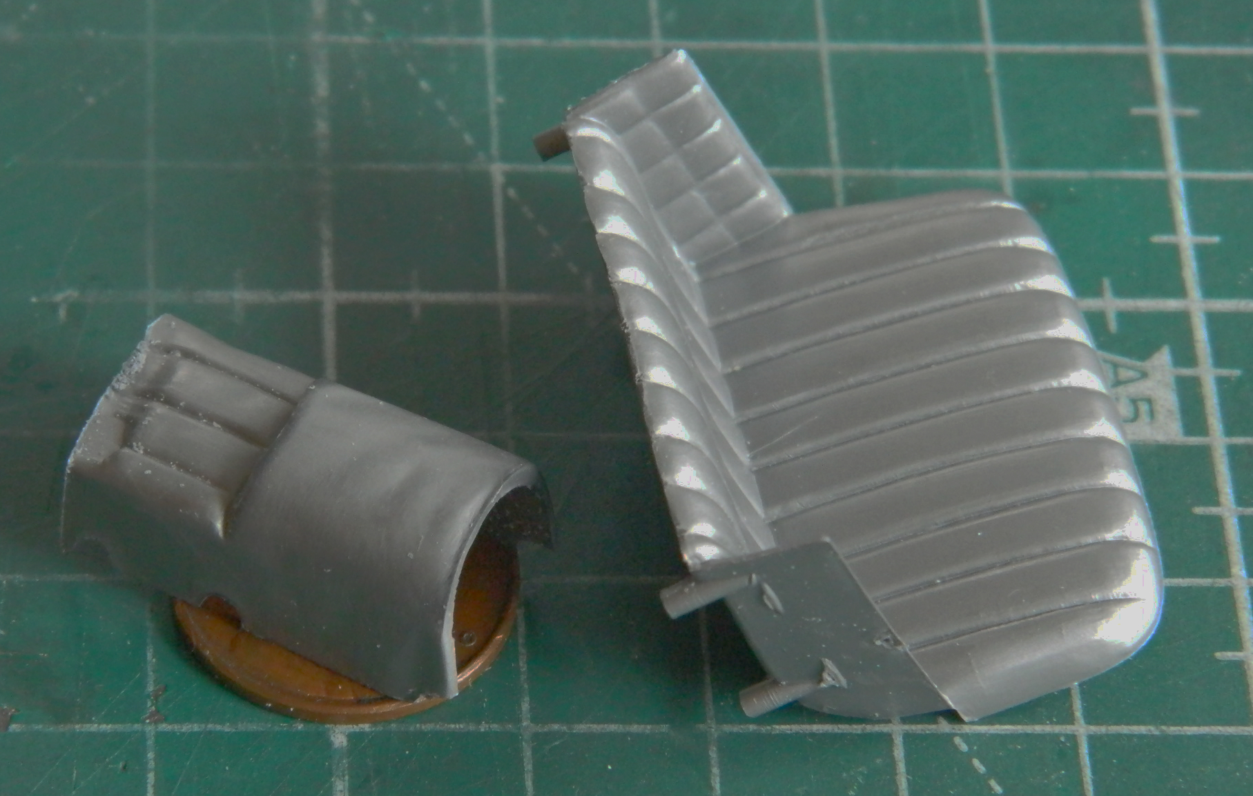
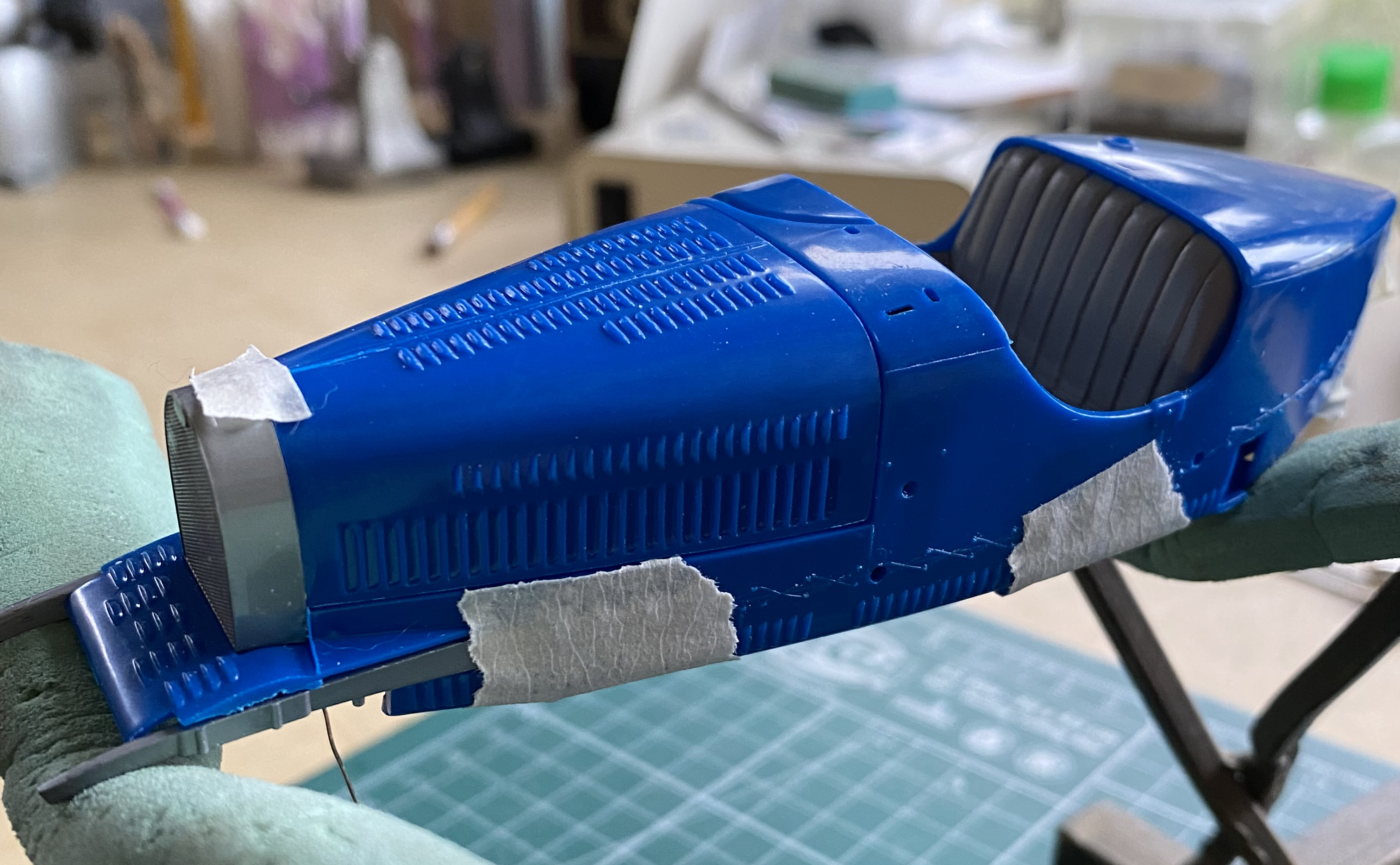
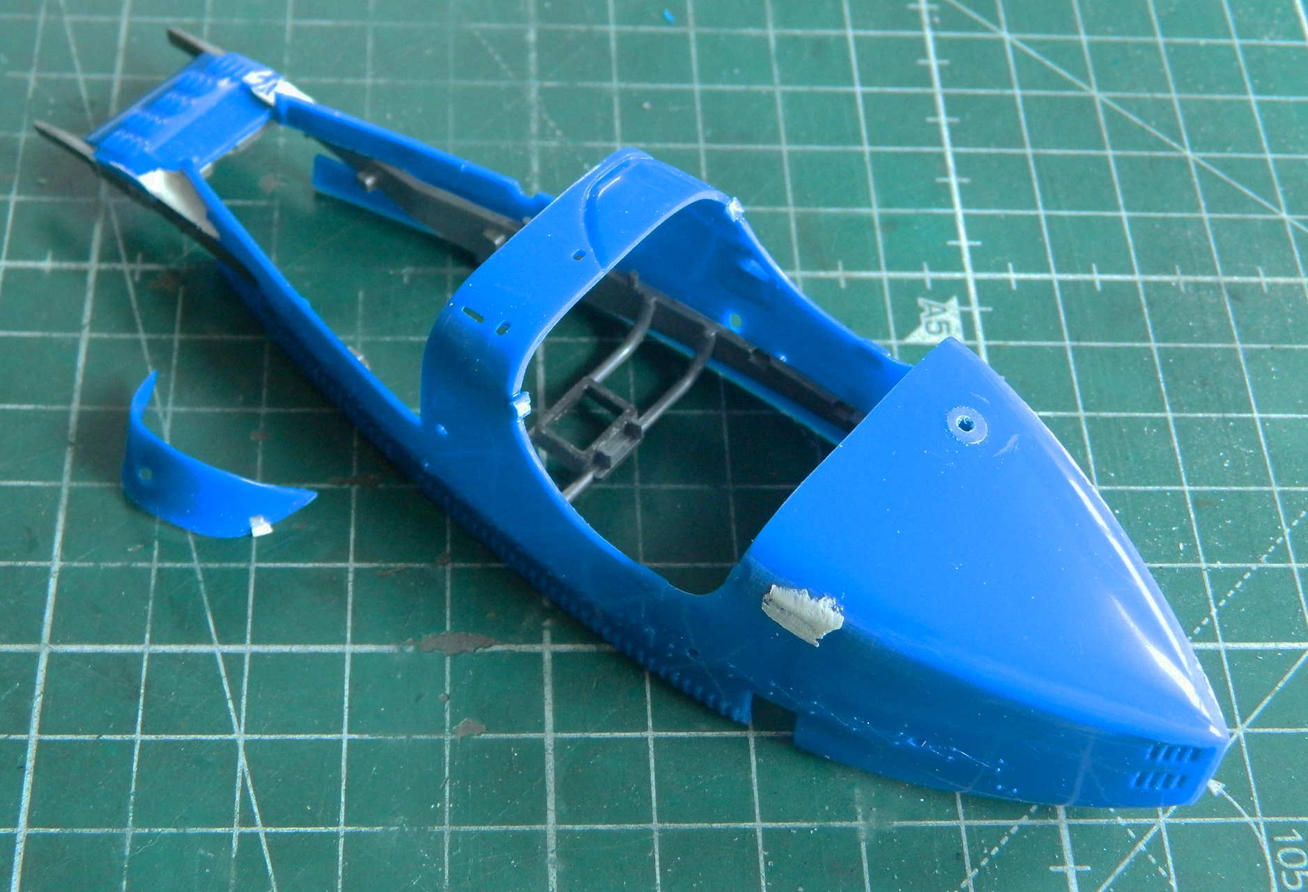
One of the things I’ll need to fix is in the cockpit. From what I can tell, when Monogram’s engineers decided to tool up this kit, they’d used an example that had been modified from the original. Perhaps this is heresy (I prefer to think it’s rationality which, not to delve too deeply into religion, might be the same thing), but Ettore had his…quirks. The cockpit of the 35B was/is cramped. And into this cramped space protrudes the transmission right down the center of it. It seems that the transmission got hot. What does cramped have to do with it? There’s no place for the driver or mechanic to go to get away from it. It seems a fairly common, albeit later, work-around to cover the transmission with a thermal blanket in the attempt to moderate how much heat the driver and mechanic were subjected to. Monogram modeled it like this:

That was cut off and later on I will add some styrene to the lower front of the seat cushion so that it looks less like a plastic edge and more like how a cushion would wrap around the seat frame:
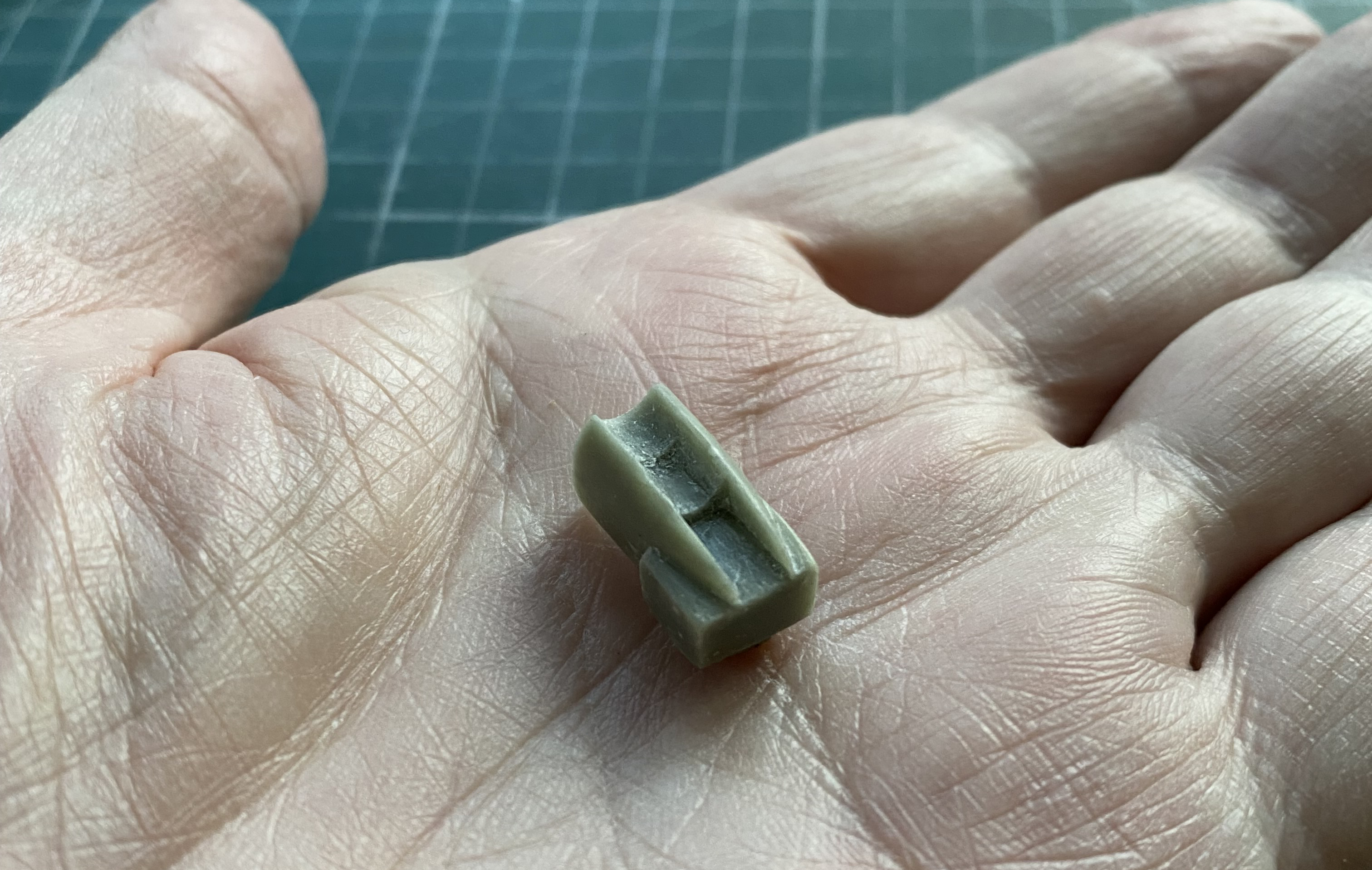
With the “thermal blanket” blob gone, I need a transmission to fill that space. I decided to use a chunk of Aves AepoxySculpt. The kit had a facsimile transmission molded to the cross members of the frame and for the Type 35, that seems to have been more accurate. Since I’m modeling a Type 35B, the one with the supercharger, the transmission is different. Once the AepoxySculpt cured overnight, I started carving away at it:
At this point I had a major cognitive disconnect. For whatever mistaken “reason,” I convinced myself (rather quickly) that I needed to 3D print this part. (For a more in-depth analysis of that nonsense, you can check this out: Old Dog, New Tricks, and 3D Printing.) I’m a bit embarrassed to say that it took me a couple of weeks to get my head out from where the sun should NEVER shine. I did (to whatever extent that’s possible). As you can see, symmetry required more accuracy:

Symmetry also required that I add putty to a few areas and the really nice thing about that is that this material will bond nicely to itself even if what it’s being added to has already cured. What fueled my excursion to Cranial Suppository Land (this time it was 3D printing…not that I think one needs to have their cranium up there to print 3D parts, it’s just not for me) was the fact that I needed the hollowed out area to fit over the bell housing of the engine. I doubted my ability (rarely a good thing, overall) to thin the sides out sufficiently without causing them to chip and break to uselessness. There was reason for caution, but not the cognitive disconnect I indulged in. Even being cautious, a few places chipped and broke away. One place I could superglue the chipped section back, but most required the addition of more putty. Perseverance won and I got it to fit over what it need to fit over:
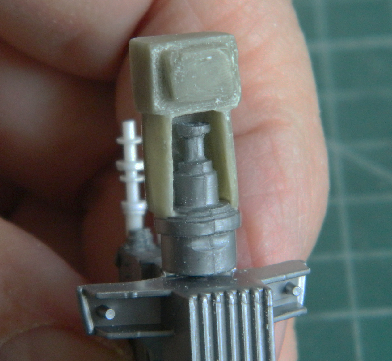

With the transmission slug in place, I checked fit and it’s okay:

Then my (low wattage, incandescent) light bulb struggled to luminescence and I figured I should probably dry-fit some other things, so I started with the engine/body/firewall/instrument bits to make sure the engine cover(s) fit as well, and to get a general sense of what I’m going to do later on (yes…I know the “thermal blanket” is there…I don’t always present things here in the exact order I do them in…another indication of being crazy):

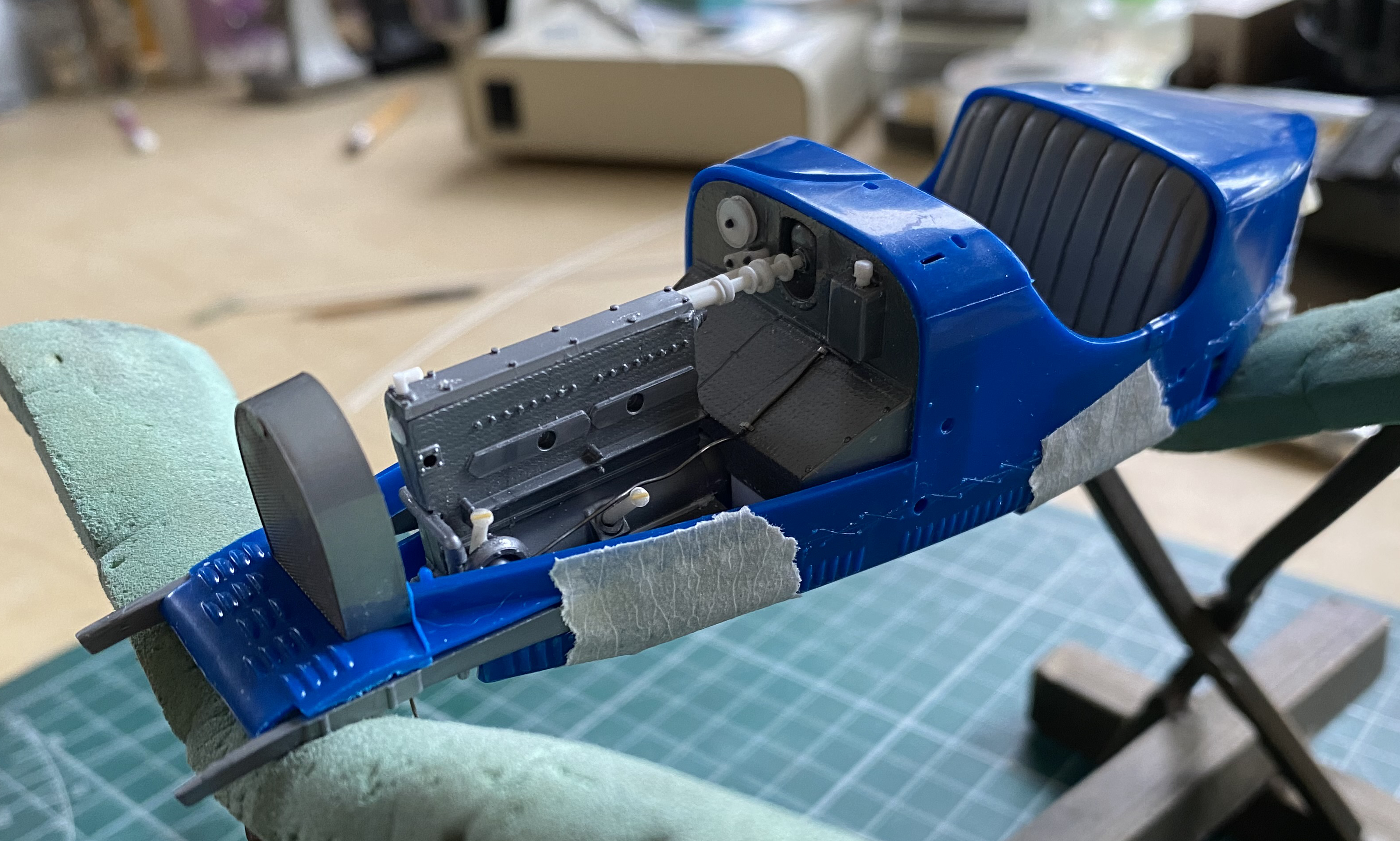
Things fit and line up.
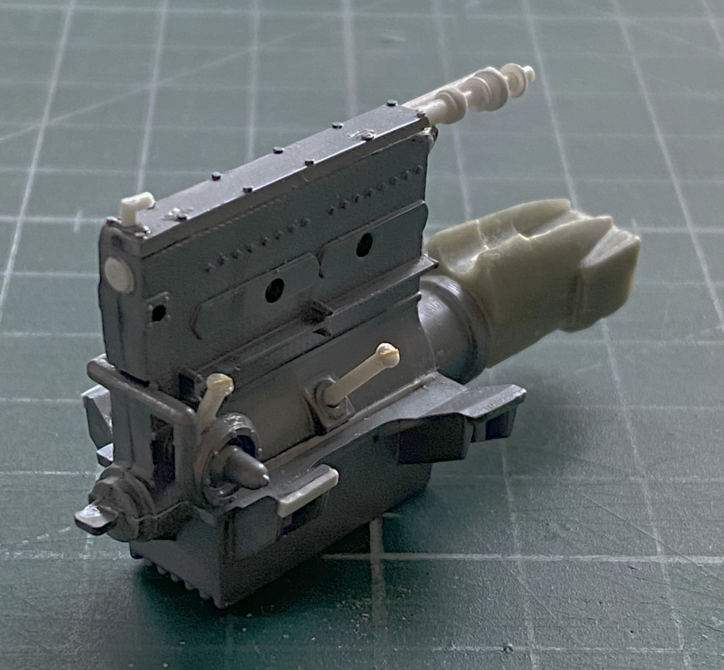
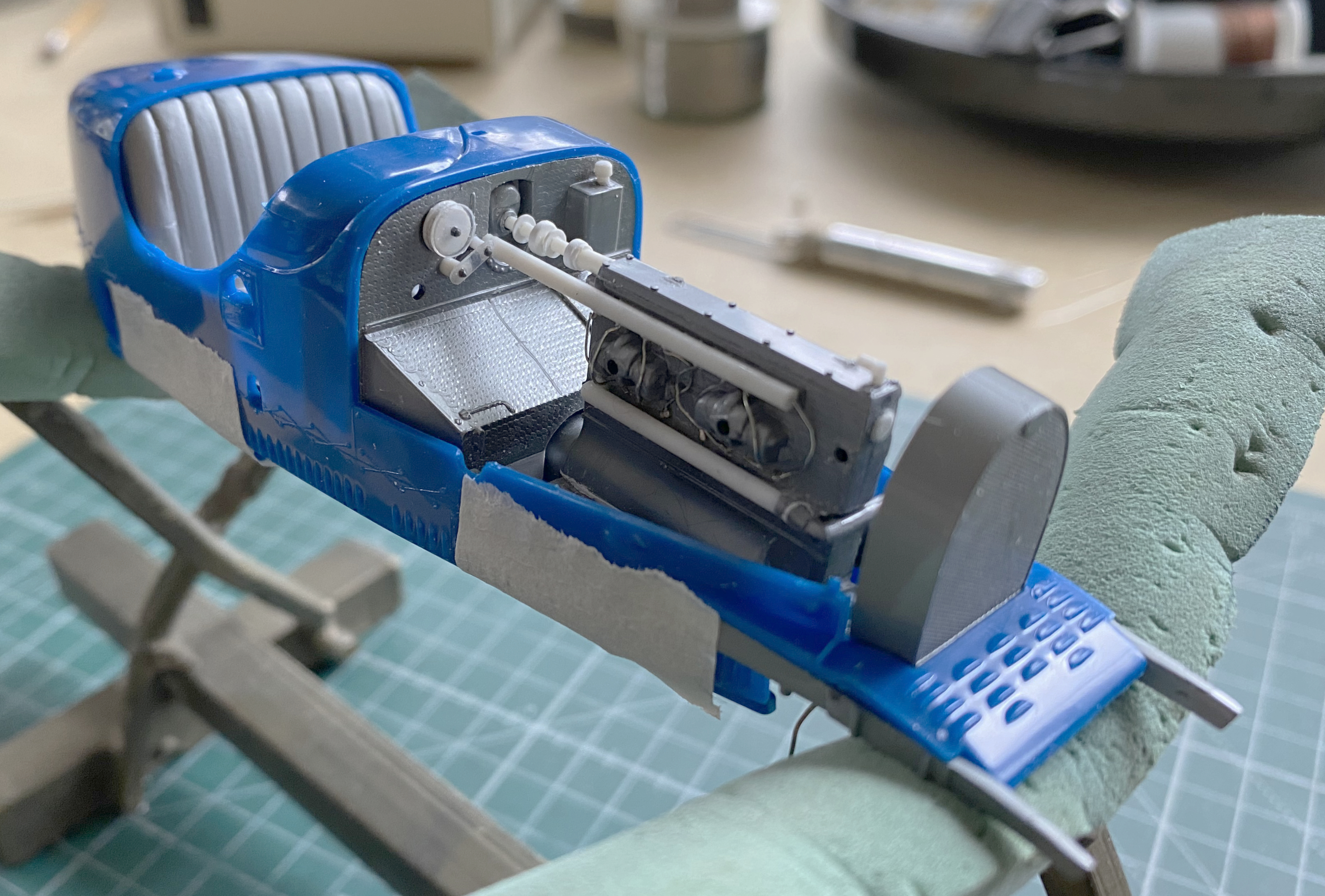
With that diversion out of the way, I set about transforming a lump of epoxy putty into a facsimile of a transmission by squaring things up, trying something new by going for bilateral symmetry, adding .005″ (.127mm) styrene, and a couple of sizes of Grandt Line bolts and resin screw heads from Archer Transfers. There is more work to do on the back of it (the square area) but I need the seat done and and the rear axle in position (dry-fit most likely) so I can align the driveshaft and shifter. The gray cylinder on top is the starter motor (yes…in 1927 this car had a functional electric starter) that I turned on the lathe from a section of sprue, and then added .015″ (.381mm) solder as the electrical feed and a strip of lead foil from a wine bottle (the car is French, so that’s appropriate) as the hold-down strap of the starter:


And for no rational reason, I decided now would be a good time to open the port in the engine cover that the over-pressure vent utilizes:

In dry-fitting the instrument panel/firewall assembly, I noticed that the firewall didn’t extend to the belly-pan of the body. I thought I’d extended it sufficiently, but I’d only extended it to the bottom of the frame; it’s my assumption that it would go all the way to the belly-pan, otherwise engine fumes would fill the car. That meant I had to add more .040″ (1.016mm) to extend the firewall down further (and at some point later I will need to replace the oil line that flexed once too often and broke):

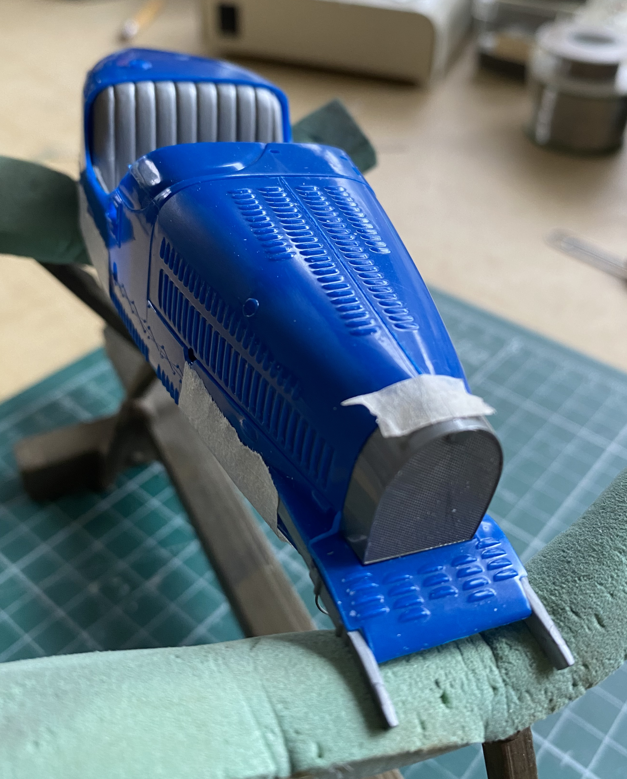
I attended to mold seams and depressions of the body with the 3M Acrylic Putty as well as filing down where the filler cap goes for a bit more accuracy (I may take that further later):

There were also mold parting lines along the lower sides of the engine compartment that I sanded down (the black is from the permanent marker I use to indicate once I have sanded out the previous sandpaper scratches…it fills the scratches and once it’s gone, so are the scratches):

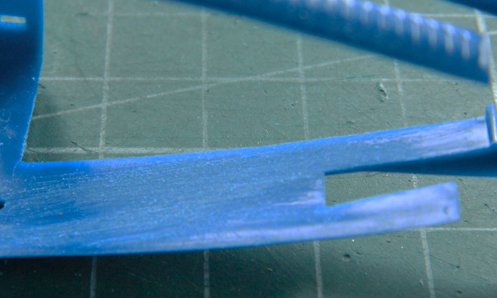

The frame of the kit is molded with the sides “boxed,” as in, a box (how odd). The car’s frame wasn’t boxed, it was a C-channel, or more like a [ channel. I wanted to represent the [ channel so first I marked where I wanted to remove plastic:

Then I realized that most of what I’d planned to remove would never be seen so I ignored what would be hidden and started cutting, carving, scraping, and cursing the moron whose I idea it had been to do this tedious task (yes, I used a mirror):

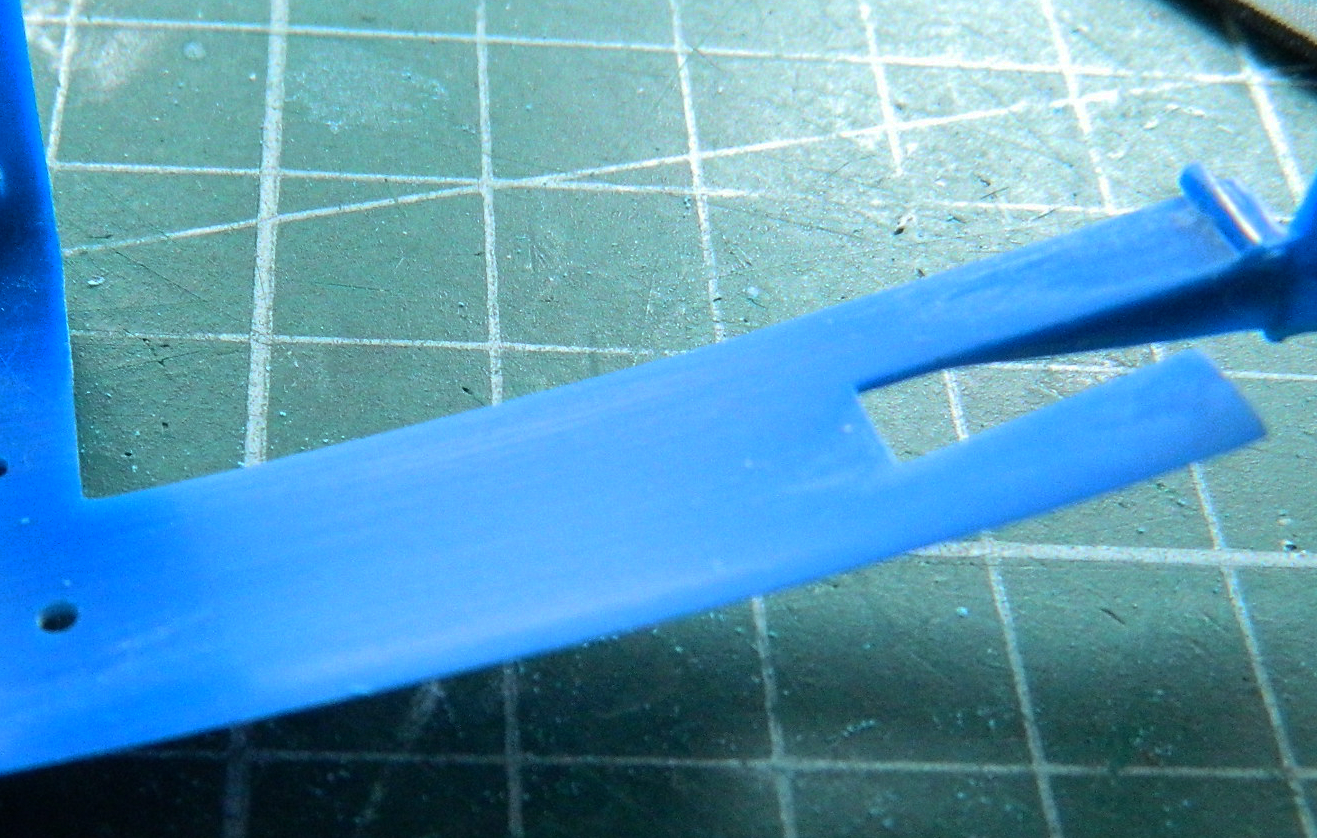
And then I REALLY started cursing when I snapped off the end of right side front of the frame just as I was finishing the task. Clearly I was spending more time patting myself on the back then I was on the task at hand that I hadn’t quite finished yet:
Let this be a lesson to all of you. Save the congratulations until it’s done done.
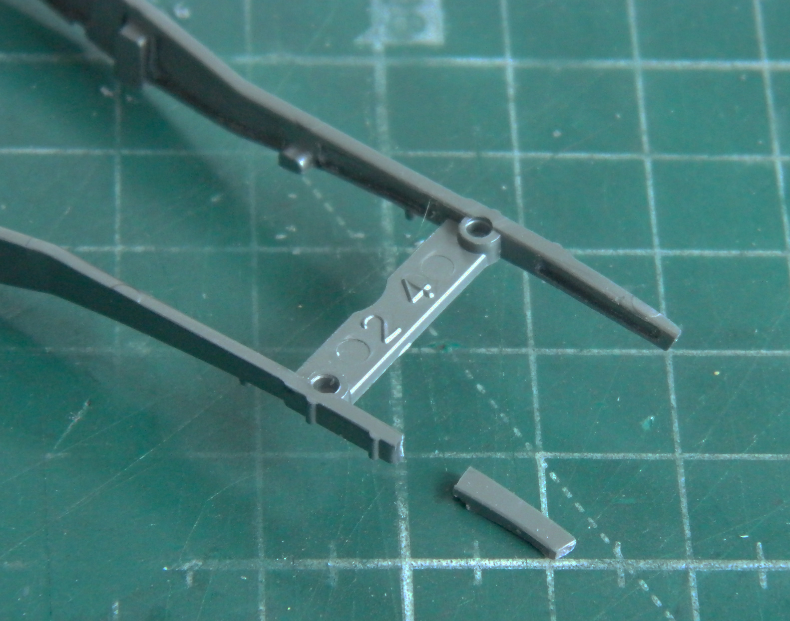
I tried gluing the end back on. These ends are a major source of support for the front axle and I wanted as much strength in the bond as I could get. So of course it snapped off again. There just isn’t enough gluing surface for the strong bond that I need. Well, bugger. Okay, okay…let’s buy another kit just for the sodding frame. Nice idea, were any available. Two hours of searching online and nothing.
That means that I’m going to have to scratch-build the right frame rail from just behind the right front engine mount out. The plastic frame is .050″ (1.27mm) thick so I’m going to bond .040″ (1.016mm) and .010″ (.254mm) to get the required thickness. The reason I’m moving so far back along the frame is for gluing surface. The frame is wider back there. I’m also planning on using two pins for structure.
I hope whatever you celebrate is good for you and yours as I am reminded that anything that drives me to drink, such as snapping a critical part off just at the end of a job, can’t be all bad.
