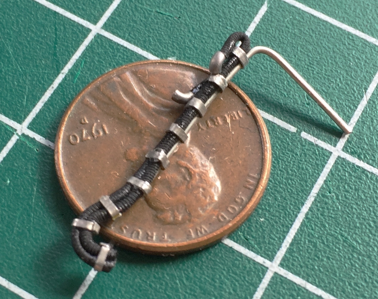
The oxygen hoses were originally purchased for aircraft builds and were just sitting on the shelf. The hose I used is 1 mm in diameter. As there are two hoses per crew member, I superglued them together:

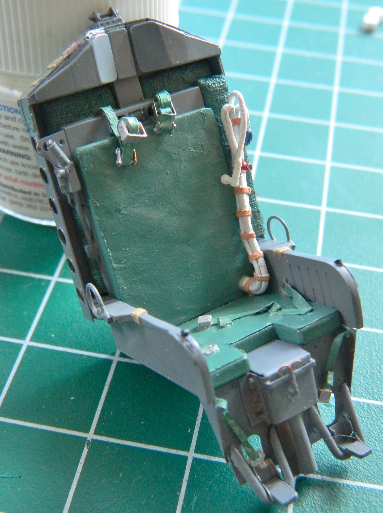
The hoses are made of what feels like silicone rubber; it’s certainly flexible enough to be and I needed something to stiffen them so they’d hold the shape I want. There’s also a communication cable bundled with the hoses which gave me the chance to use a copper wire to allow me to bend the hoses to the desired shape. I used lead foil for the straps and solder for the suit connectors (and of course I drilled out the ends of them):
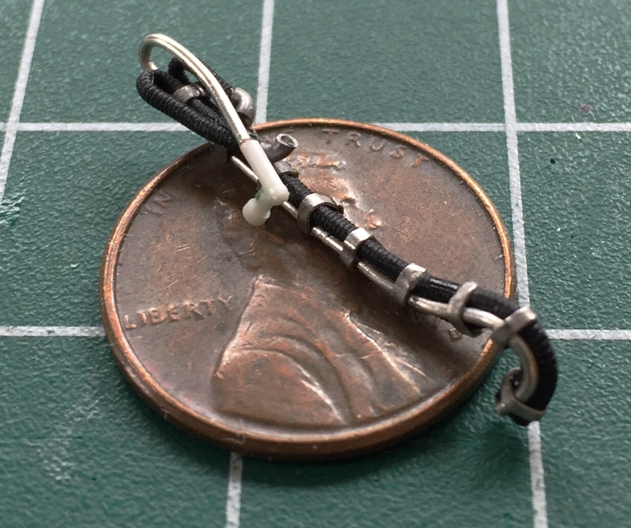
Then I made the electrical connection and added that to both hose assemblies:
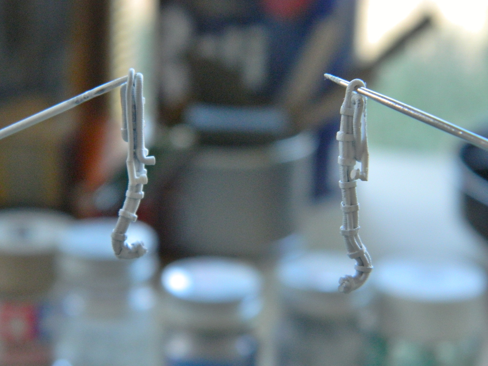
The base coat is white:
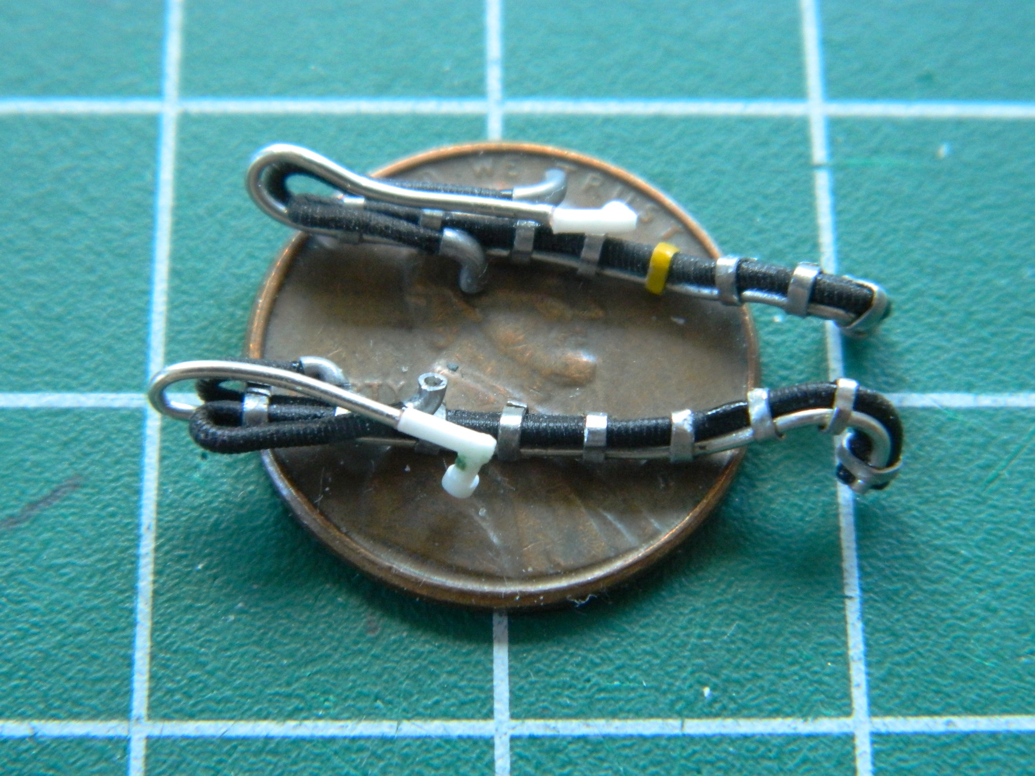
The straps are buff and the hose connectors are painted either red or blue. That completes the hoses:

The hoses were the last parts I needed to finish seat assemblies:
First major assembly! Assemble the crew cabin:
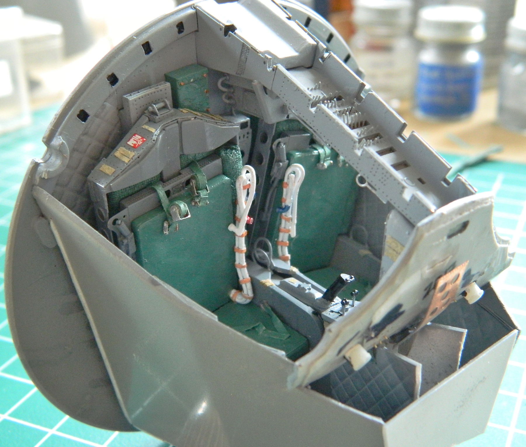


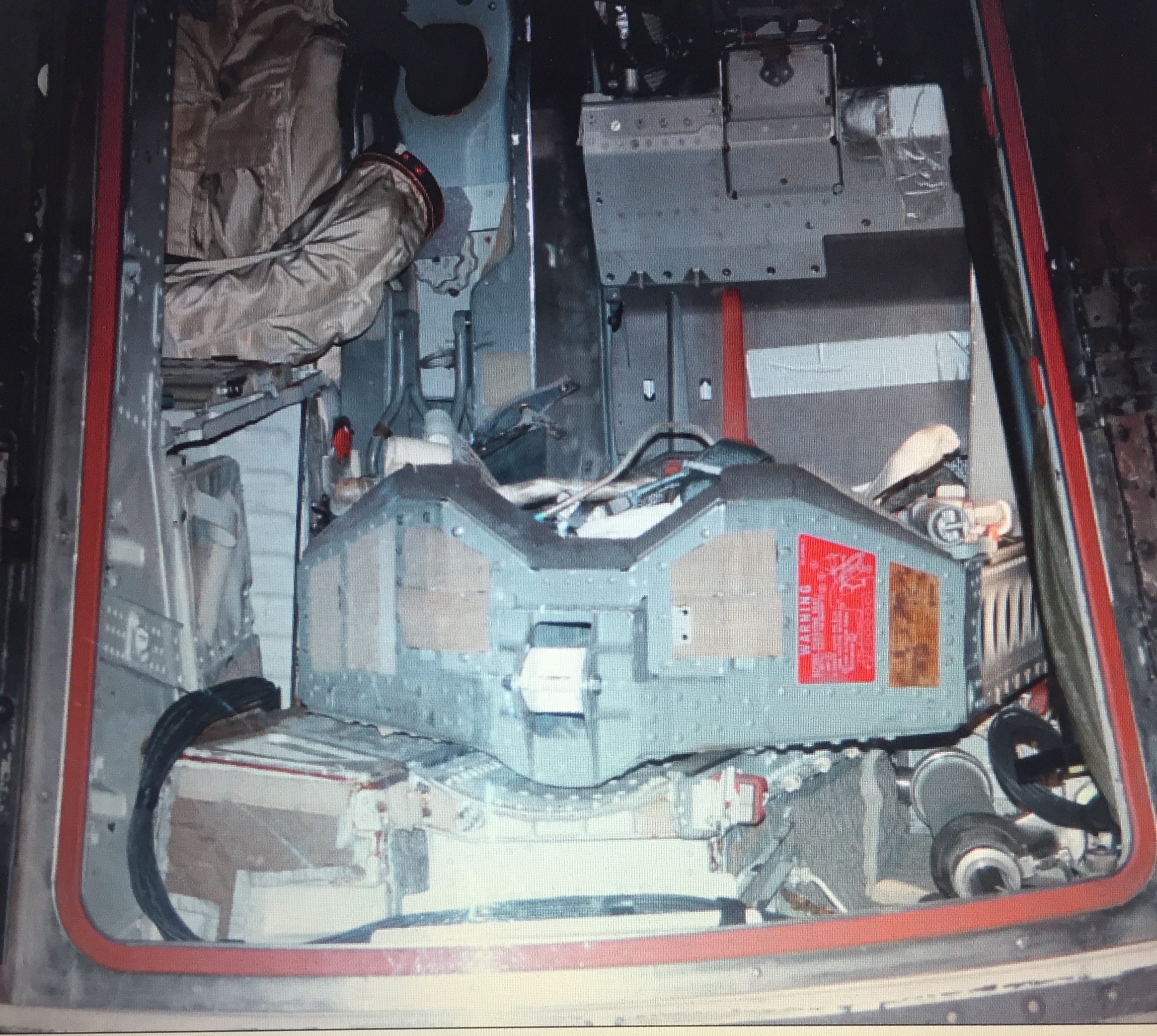
With the cabin assembled, it was time to stuff it into the body of the capsule. There was only one small problem with that. IT DIDN’T FIT:

When my head ceased exploding (like, the next day), I started checking references to see where it was off (other than…well…EVERYWHERE). The seats on the actual capsule don’t sit as far back as what I had sitting on my bench:

Okay…aside from the fact that the back of the interior assembly was STICKING OUT OF THE BACK, that indicated that the interior assembly wasn’t getting in far enough (“Captain” Obvious? Try “Colonel”). Well, I did fit that thing and it did fit. Why doesn’t it now? What’s changed?
The last time I stuffed that cabin into the capsule, nothing was glued together, it was all taped. Hmm… Evidently being taped together allowed just enough flexibility in the location of the parts for it to conform to the space available. But now it’s all glued (quite thoroughly) together and there is NO flexibility of location. That indicated to me that I didn’t need a lot more room inside the shell, just more room. Okay…I can work with that (I hope).
I had already removed as much from the corners of the cockpit tub that I could without breaking through the walls. That meant that whatever space I needed had to come from the inside of the shell. I used 100 grit sandpaper and scoured the inside of the shell. I figured out a handy trick to discover exactly where the tub was hitting the shell. I ran a bead of petroleum jelly along the edges and pushed it into the shell. When the tub was removed, the petroleum jelly left some of itself where it was contacting the tub…and that’s where I concentrated my efforts at material removal. And then I got to the point where the petroleum jelly wasn’t leaving any deposits inside, yet the damned thing still didn’t fit. It took some time and clever use with a flashlight but I discovered the last impediment to a proper fit.
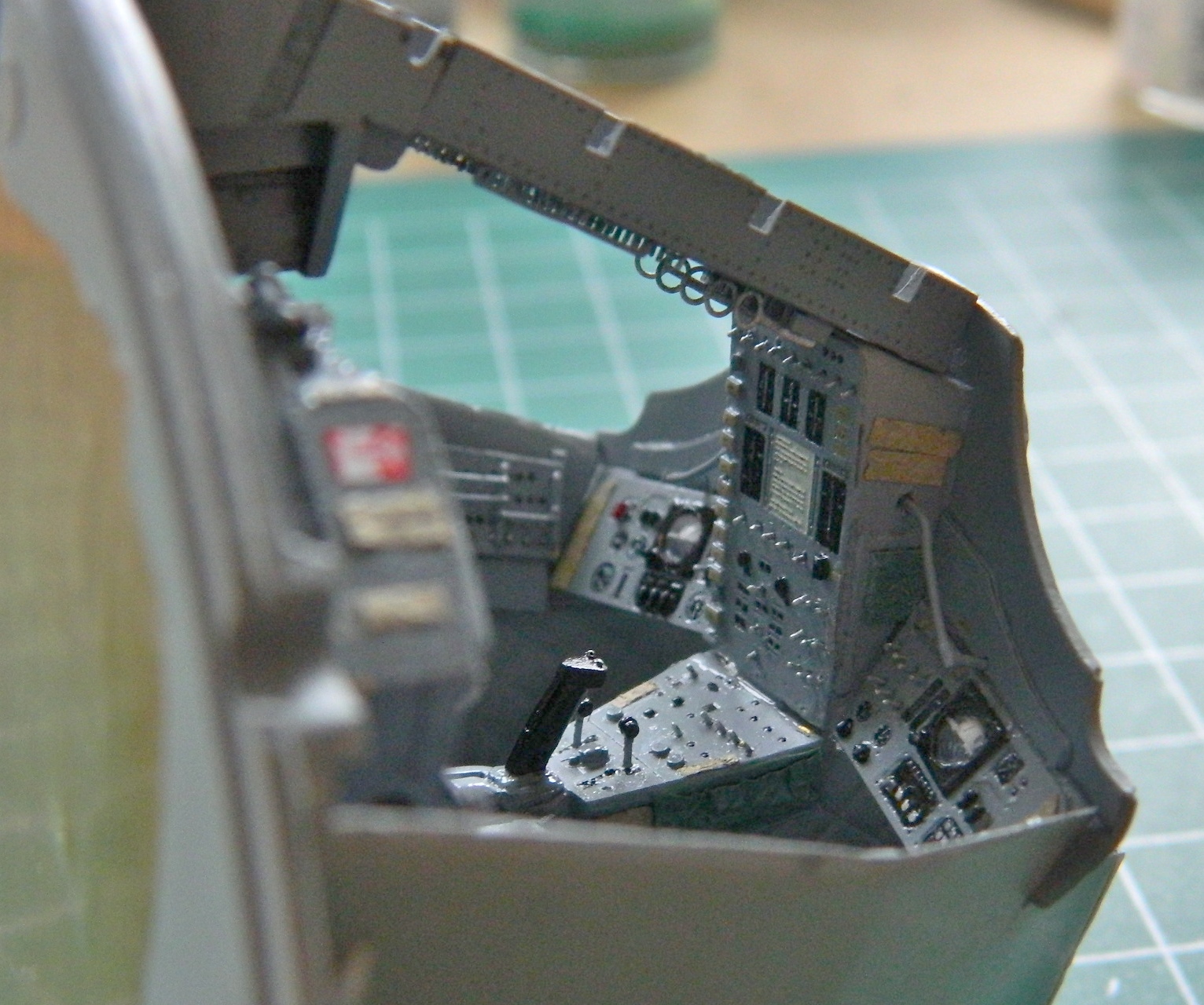
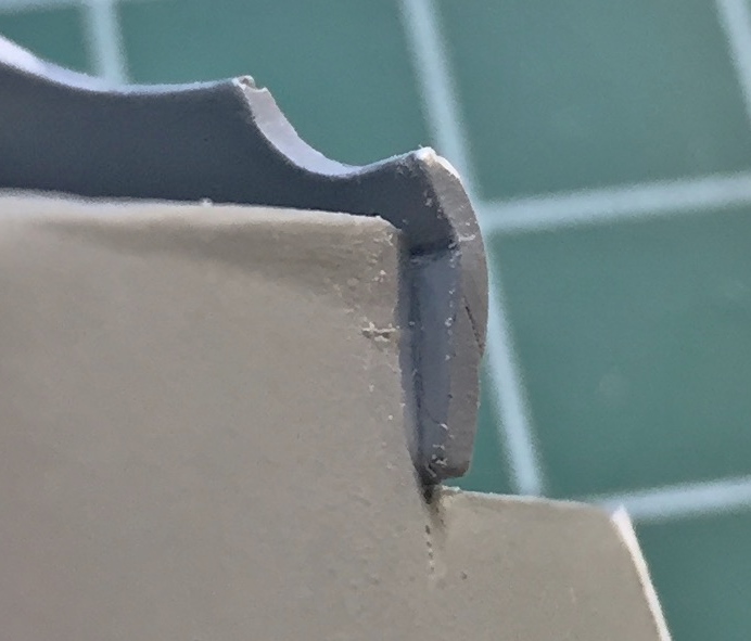
It was the edges of the instrument panel. The little protrusions on each side had to come off:
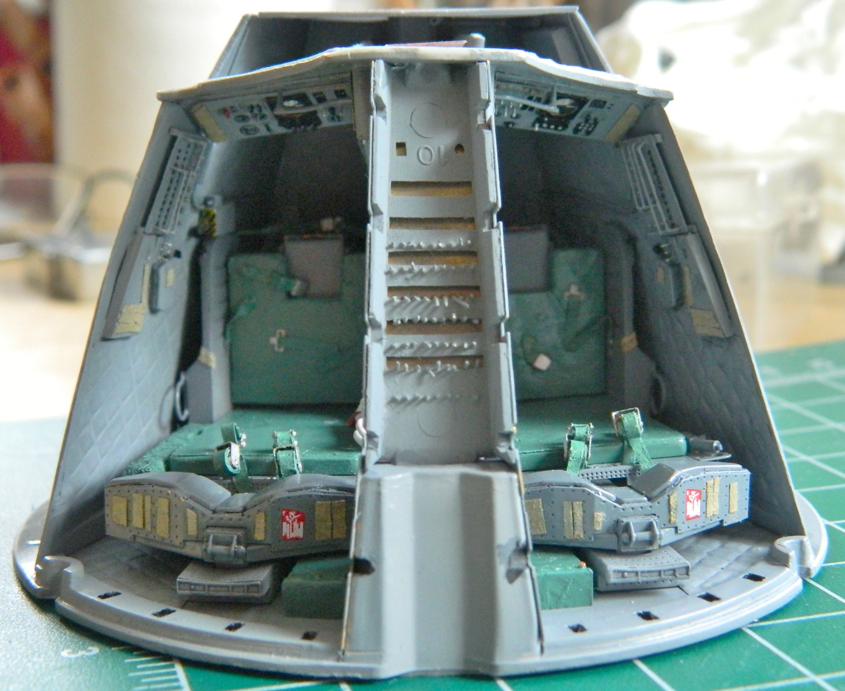
And after a couple of hours of dicking around with it, I finally got it to fit:
The last parts I had to add before I could button up the capsule were the hatches. I used some styrene tube to make the front hinges [As an aside, I am NOT AT ALL PLEASED with how the hatches hinge. But short of reworking the corners of the instrument panel to an accurate configuration and making more accurate hinges, that’s what I’m stuck with.]:
With the hatches in place, now I can stuff the interior into the hull and glue it in. Here, as well as far too many other places, the fit is abysmal. I had to use superglue jell to fill the spaces between the outer edge of the rear bulkhead of the cabin and the interior surface of the hull. When I say I had to jam the interior into the hull, that’s exactly what I had to do. Once I’d run a (wide) bead of jell around the mating points, I put the base of the capsule on a flat surface and added weight to press the cabin assembly as deeply into the hull as it has to be. Superglue jell takes A LONG TIME to set up. I put the hull/interior aside and let it cure for over twelve hours:
The next day the jell had hardened so I glued the heat shield into place, finishing the interior construction:
With that odyssey take care of, attention and effort turned to the exterior…and there’s plenty of attention and effort required.
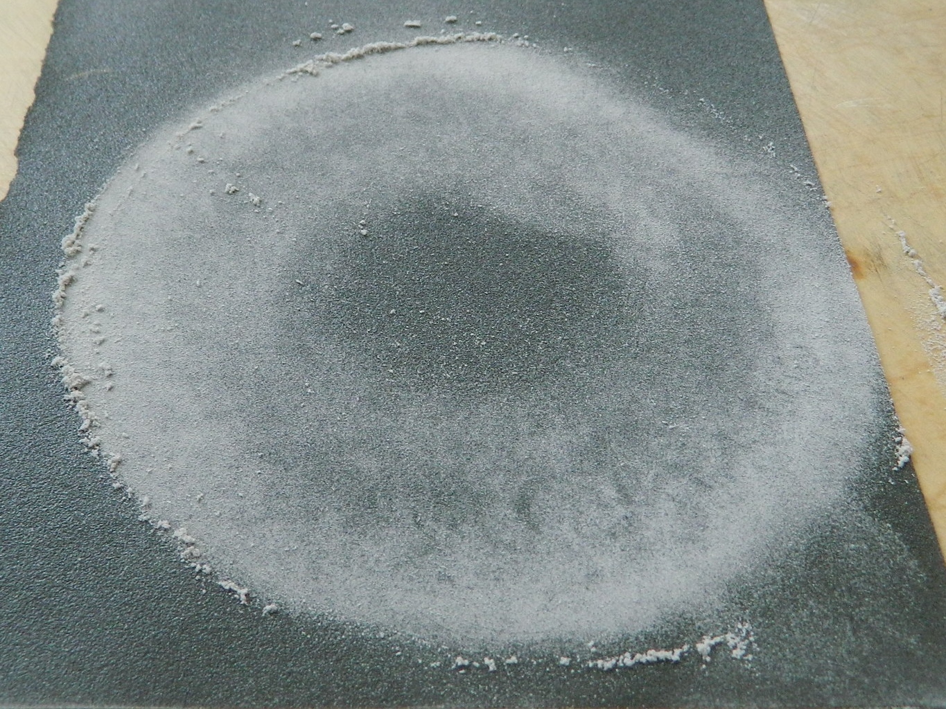
There are two modules aft of the capsule. The closest module is the section that contains the de-orbit engines (aka, retrorockets), and the module furthest from the capsule is the service module where fuel cells, batteries, oxygen, and the like are contained. The end of the service module wasn’t flat, so I placed a sheet of 220 grit sandpaper on the table and sanded the high spots down:
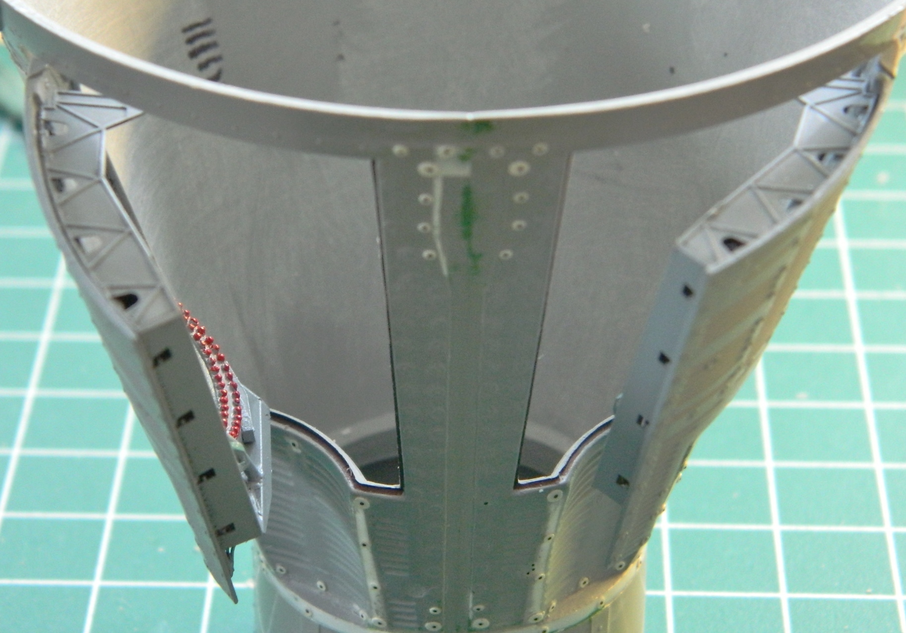
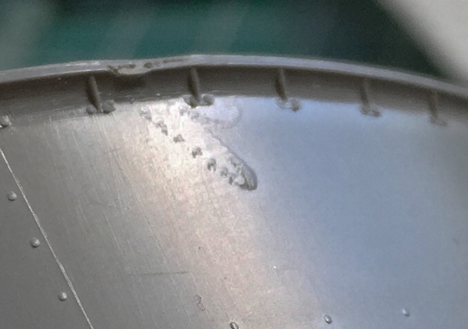
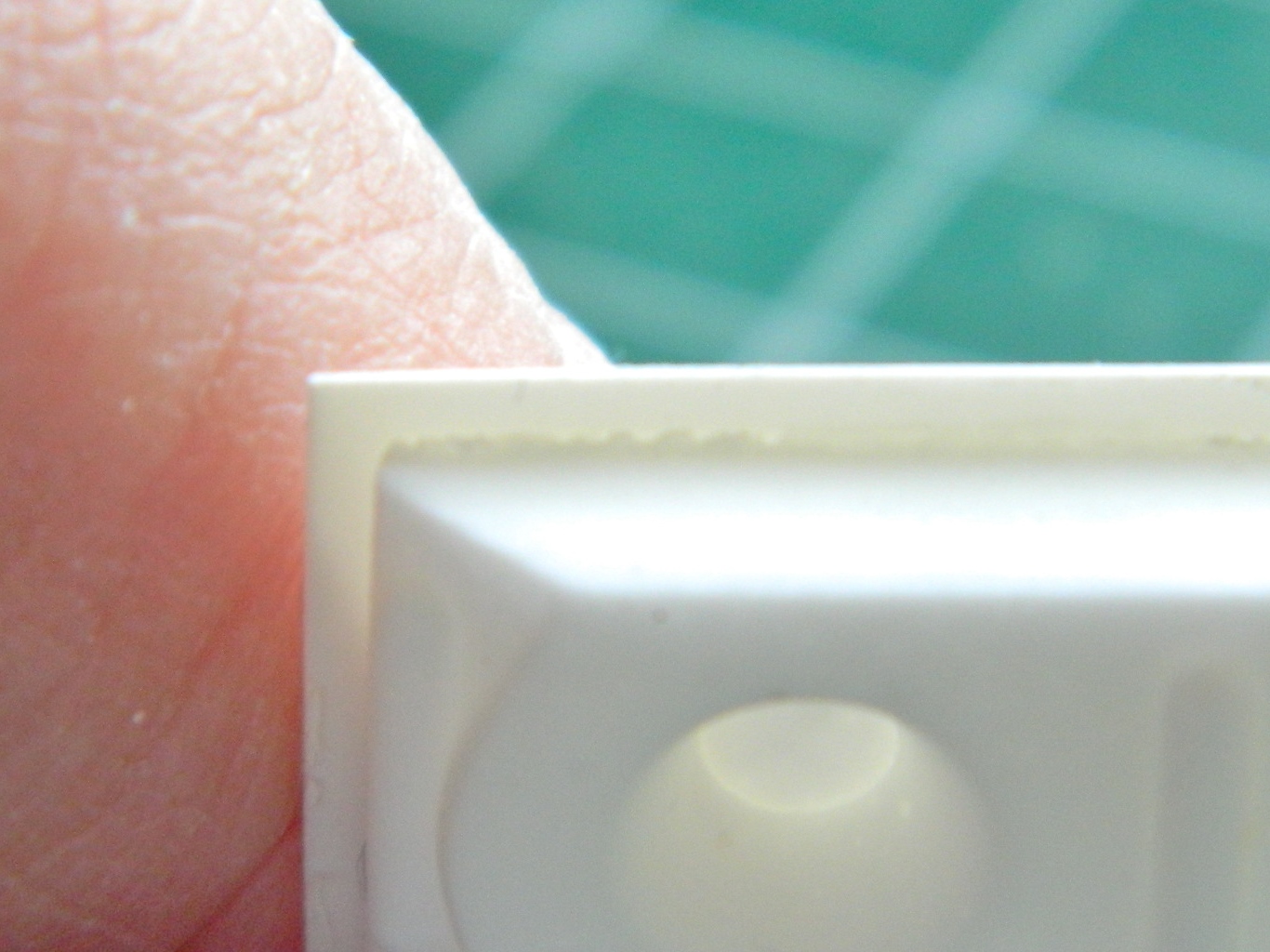
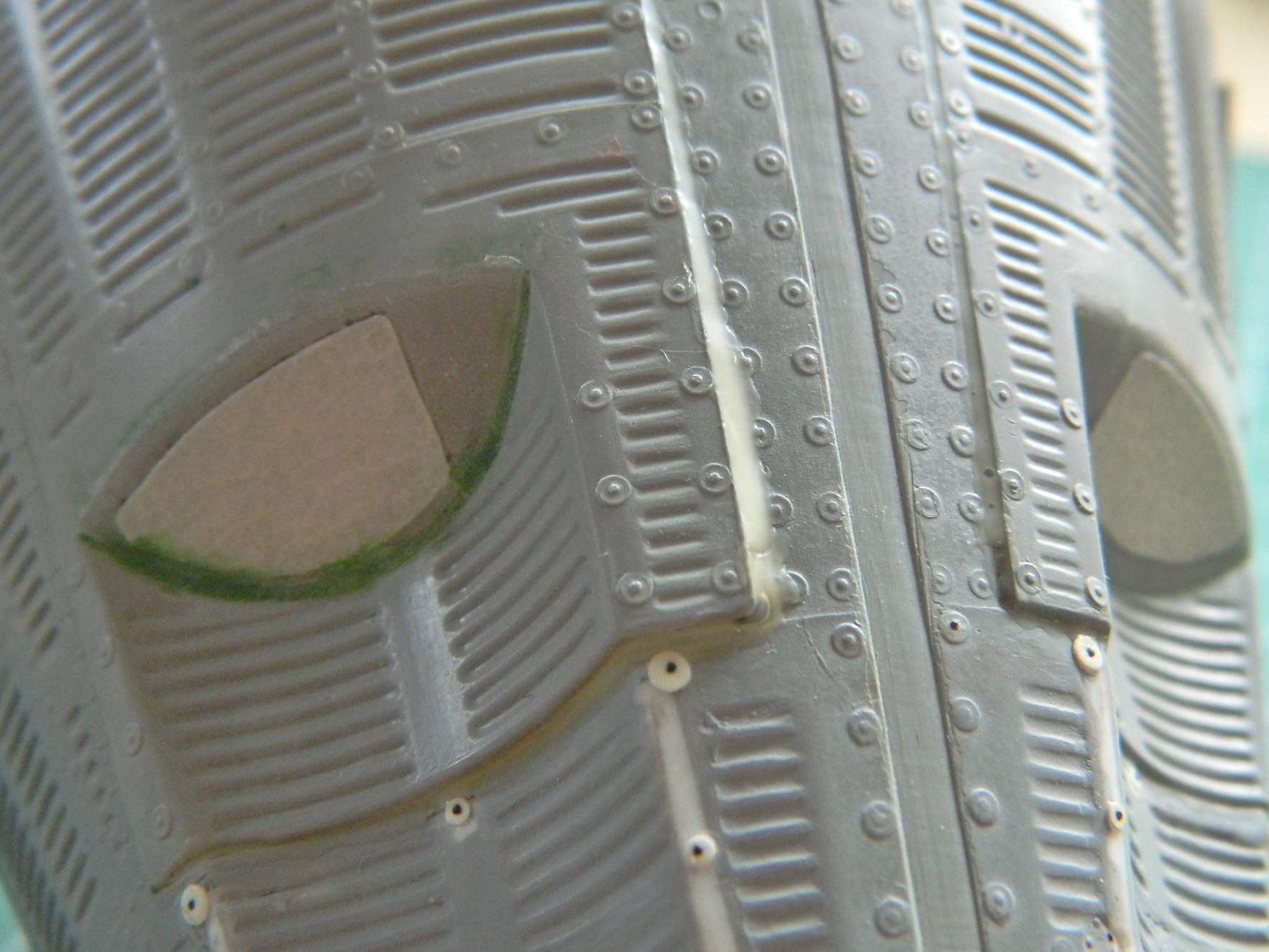
All the problems I’m having with the kit parts were engineered into it, guaranteeing problems. I don’t think that was Revell’s intention, but that’s how it is. In my kinder moments (rare that they are), I suspect the person(s) who cut the dies for this kit wasn’t a master die cutter. I don’t think they were journeymen. I suspect they were new-hire apprentices. And what makes me think that? In the next photo, that U-shaped area is a positive; it sticks up from the surface. That means that when the dies were being cut, the die cutter tool (I mean the tool…I’m hoping the person holding the tool wasn’t also a tool…) skipped across the surface of the die and left a groove behind. And I mean left a groove behind! What sort of quality control lets something like that out of the die cutter shop and into the production area? Nothing I can say would be a “kinder moment”:
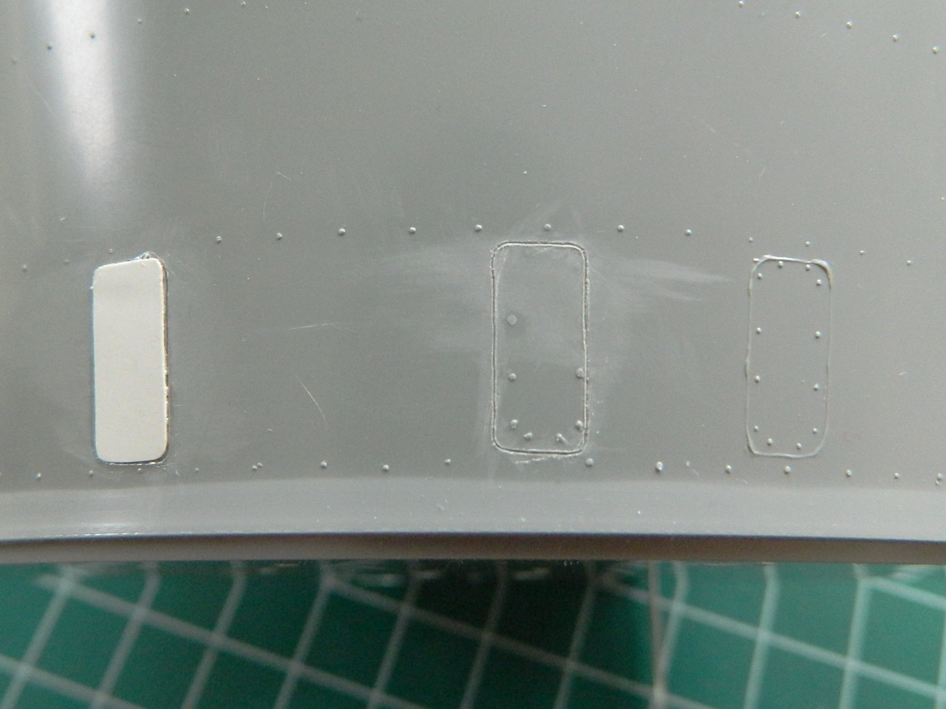
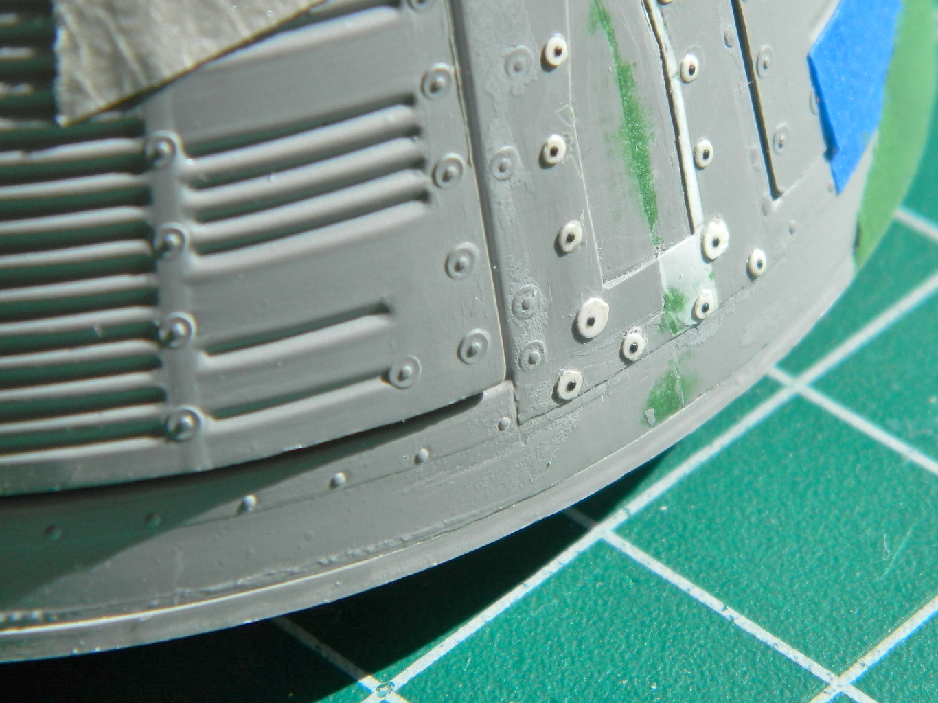
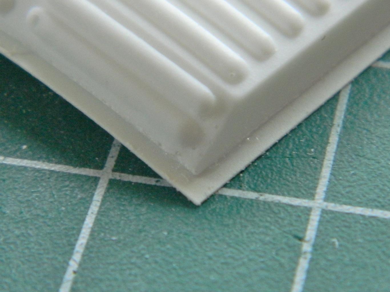
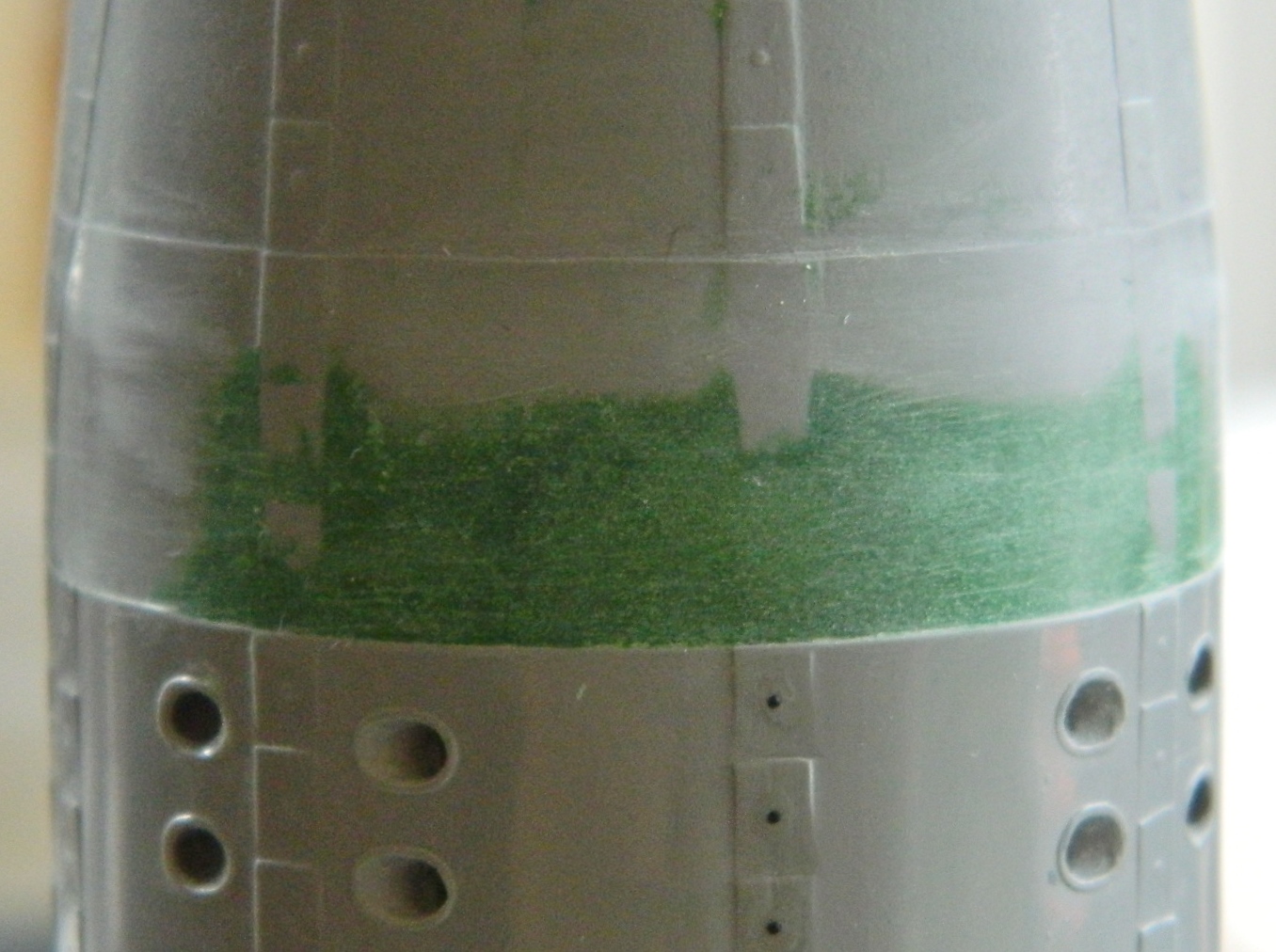
There are panels on both the retro and service modules. On the kit they’re hinted at with REALLY LOUSY raised lines. The lines are inconsistent in height, shape, and any other factor that makes them what they are…instead of what they should have been. So they have to be redone…and the usual way to do that is to scribe into the surface the raised lines.
Major problem with that task is personal. I hate scribing panel lines. Thus far, no amount of practice has made me any better at doing it. (Hmm…maybe I can get a job with Revell cutting dies?) (Meow). This photo shows the abysmal raised panel lines on the right, my crappy attempt at scribing in the center, and what I finally decided to do instead. Add panels to the surface:
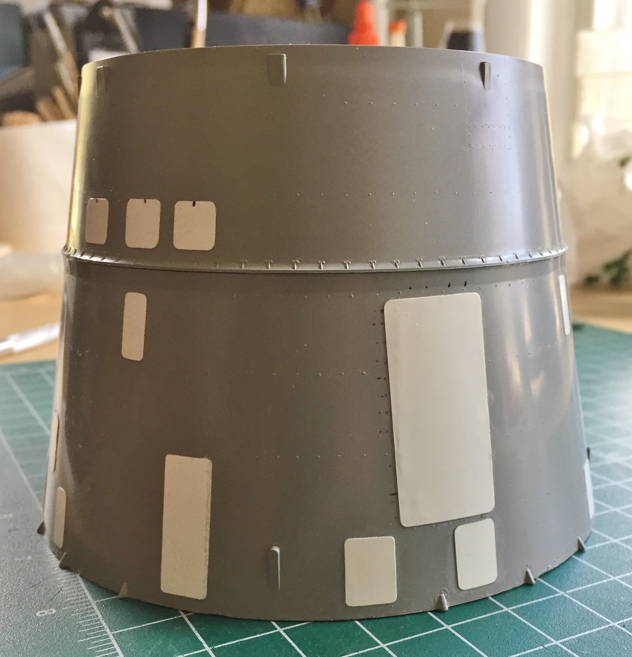
Yes, on the actual spacecraft, those panels weren’t on top of the surface. But the accuracy of this model is bloody atrocious, even after all my work, so one more inaccuracy with this build is just another bucket of sand on the beach:
I doubt you’re surprised at this point (I certainly wasn’t), but the heat shield doesn’t quite fit well on the back of the capsule:

Initially it seems like an easy fix. Just file down what extends past the edge of the capsule and add plastic to where the heat shield doesn’t quite meet the edge of the capsule. The problem with that is that this heat shield also has to fit the top of the retro module and if I did that, it wouldn’t fit at all. I had to make the edge of the capsule conform to the shape and edge location of the heat shield. Putty time:
Not my preferred way of doing things but that’s just what this [INVECTIVE DELETED] thing requires.
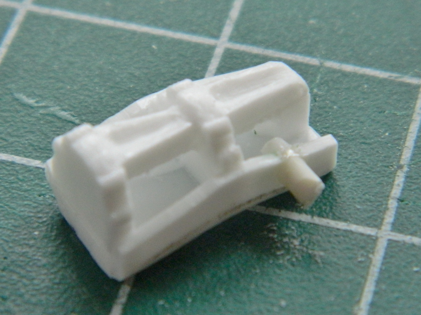
Next step was to use the resin AM parts to replace the incorrect kit items for the orbital maneuvering system (OMS):
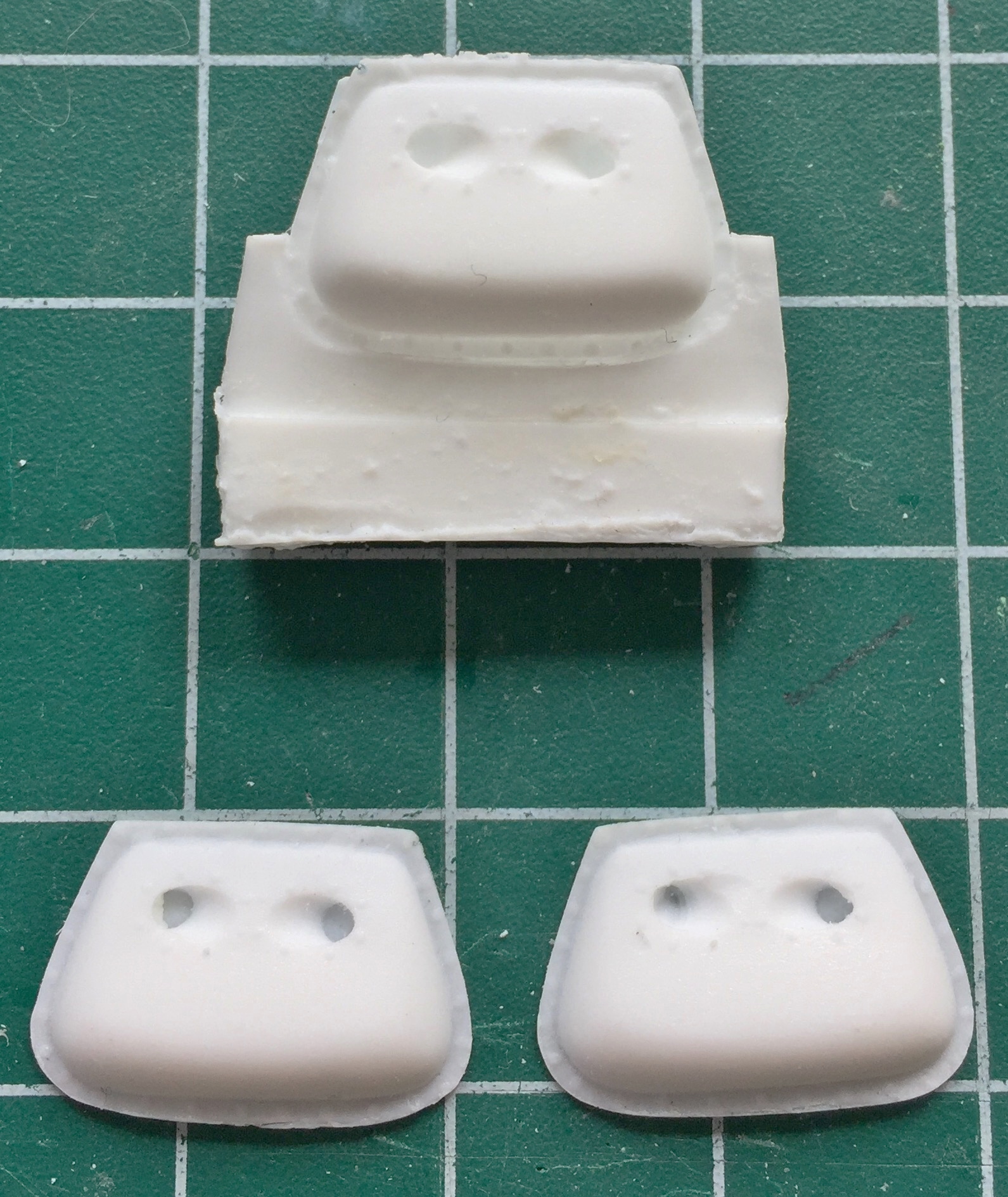

And here I encountered another disappointment. Yes, whoever built the masters for these parts did an adequate, NOT good, job. The OMS parts that go on the outside of the retro module are too tall. References show they should be half the height than what was provided in the set. Also, though I am not a professional mold maker or resin caster, at least I know that resin casts better and denser under pressure. This idea had not occurred to whoever made the molds and poured the resin into them. The castings are FULL of bubbles, some of which show up in the least opportune places, and the handling of the masters during mold making only left one thing to be desired.
Care.
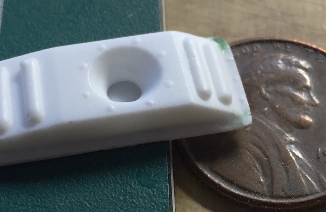
The edge of this OMS unit was poorly cast and had a very pronounced bubble along its edge. To fix that I cut away the mounting flange and replaced it with a sheet of .010″ (.254mm) styrene:

On the other side of this OMS pack, close examination of the flaw at the edge in the picture below was molded that way. That meant the damage to the master was already done before the mold was made. Gosh…what a surprise it showed up in the casting:

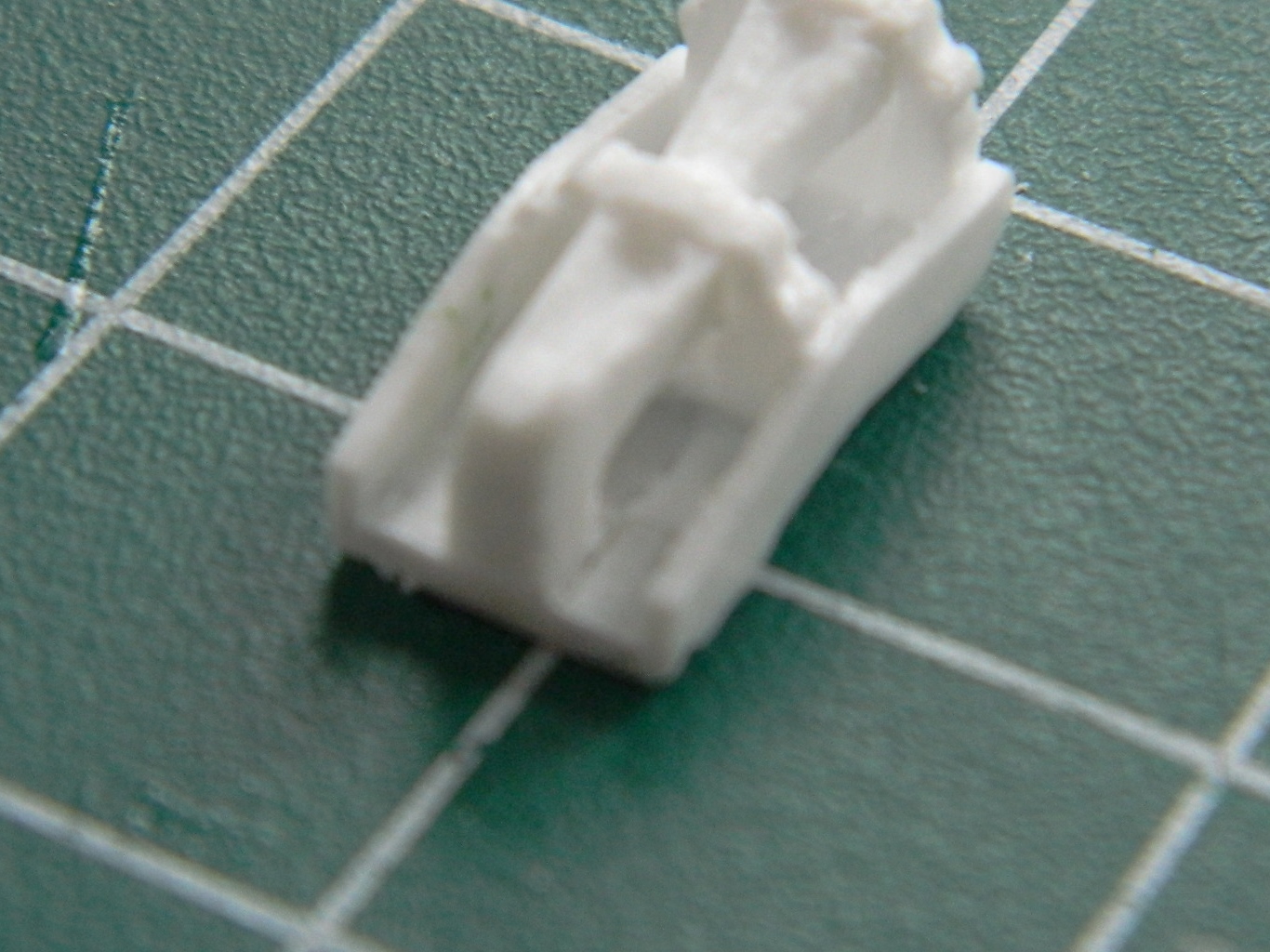
This part is supposed to represent the horizon sensor. The bubbles were large enough that putty would not have fixed them. Instead I opened the bubbles so that I could insert styrene to fix them (and subsequent checking of references showed that it’s pretty inaccurate generally; I fixed it to the best of the reference’s detail…which wasn’t enough, but there it is…again):


This part, a wiring shroud, also had a couple of large bubbles also (the smaller ones on the face could be filled with putty) that needed plugging:

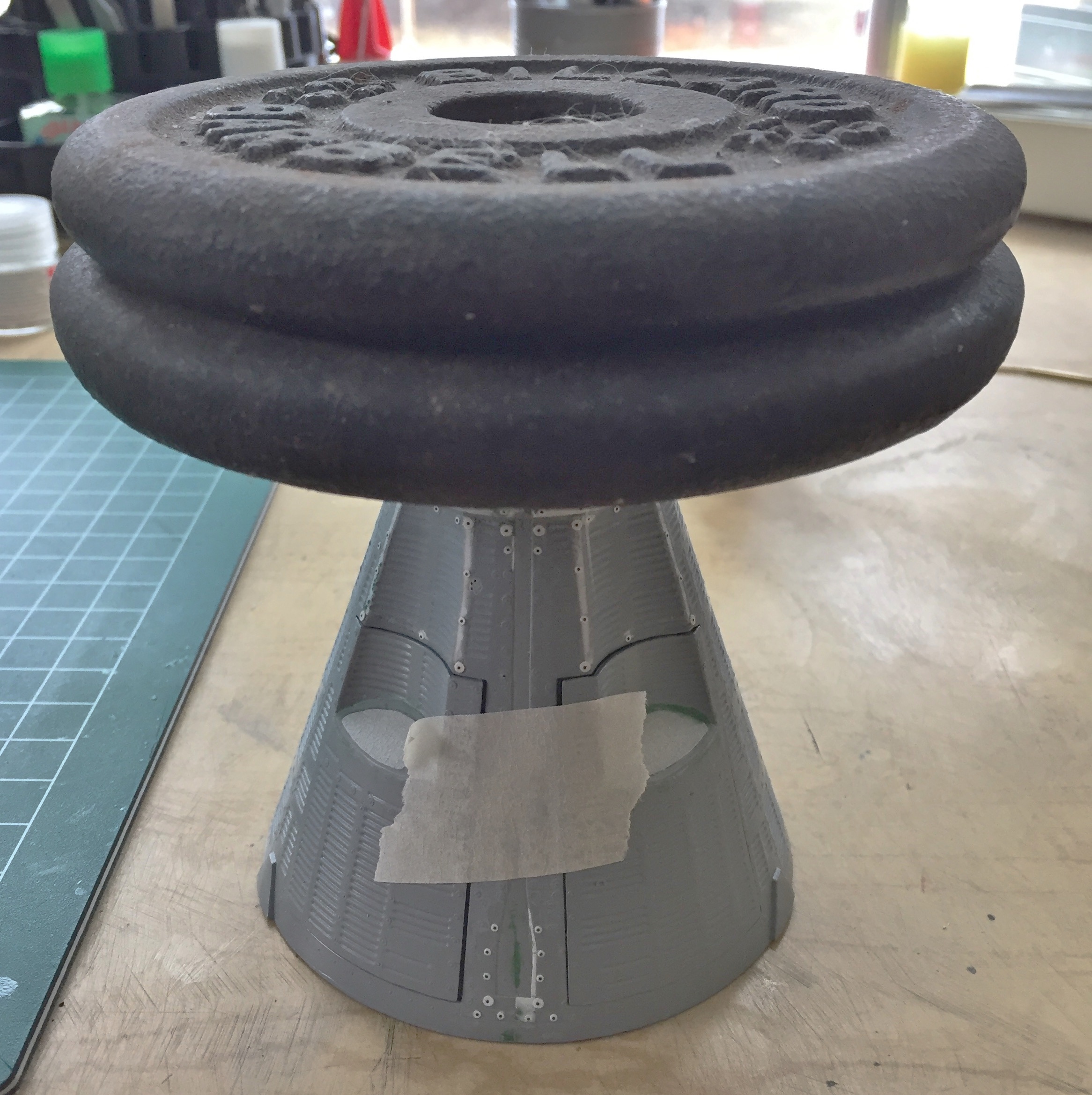
Before I could add the resin AM parts, the retro module had to be glued to the capsule. The kit provides rudimentary details for the inside of both retro and service modules. Because I can’t find any reference photos of exactly how things were mounted, wired, and plumbed, I’m not adding those details. The only exception were the braces for the retrorockets. Initially it was because there are a couple of locating pegs to mount the service module. As I’ve been working on this and considering exactly how I was going to hold this thing while I painted it, I realized those engine braces would do quite nicely as a painting handle:

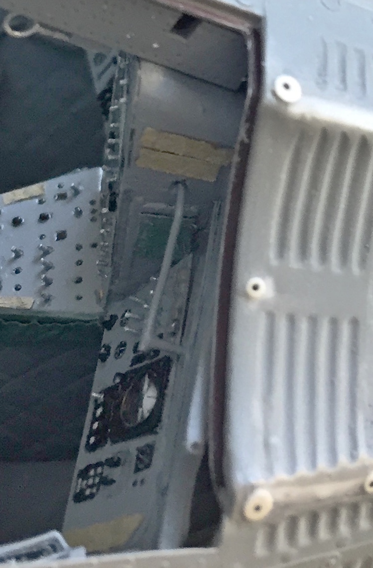
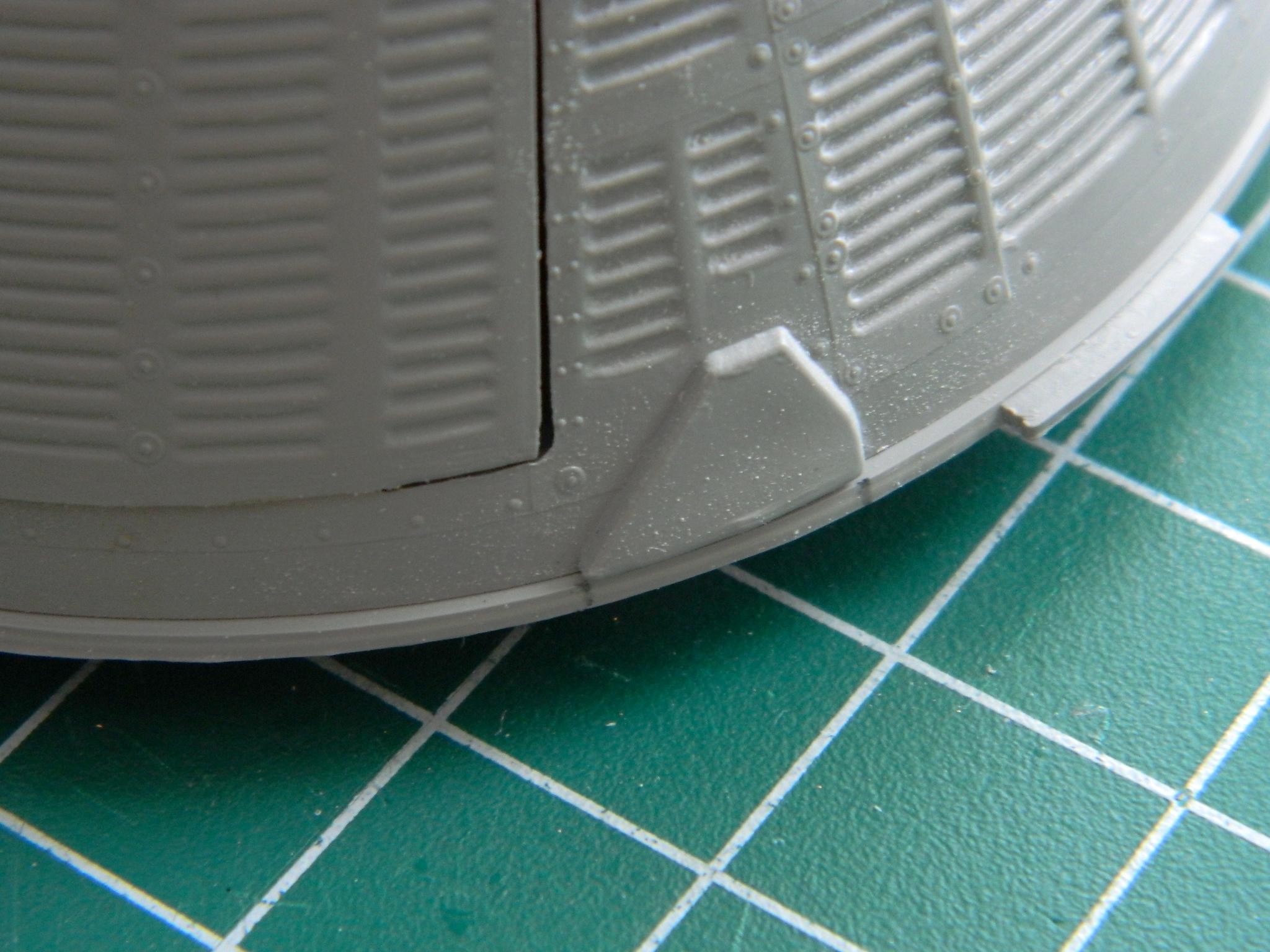
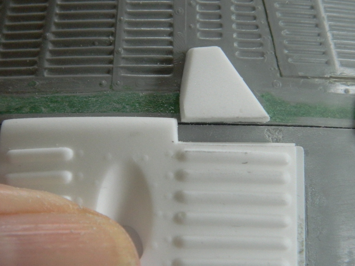
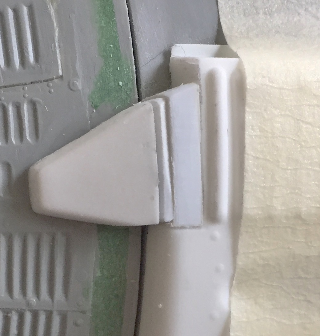
After adding the OMS packs to the service module, they needed to be added to the retro module, which is where most of them go. When I went to add the OMS packs to the sides and align them with their respective wiring shrouds I found another fit problem. The wiring shroud shown below is where it belongs. To get the OMS pack to meet up with it the way it’s supposed to would mean that the OMS pack would be MUCH more forward than references show, or, the wiring shroud would be too far rearward:
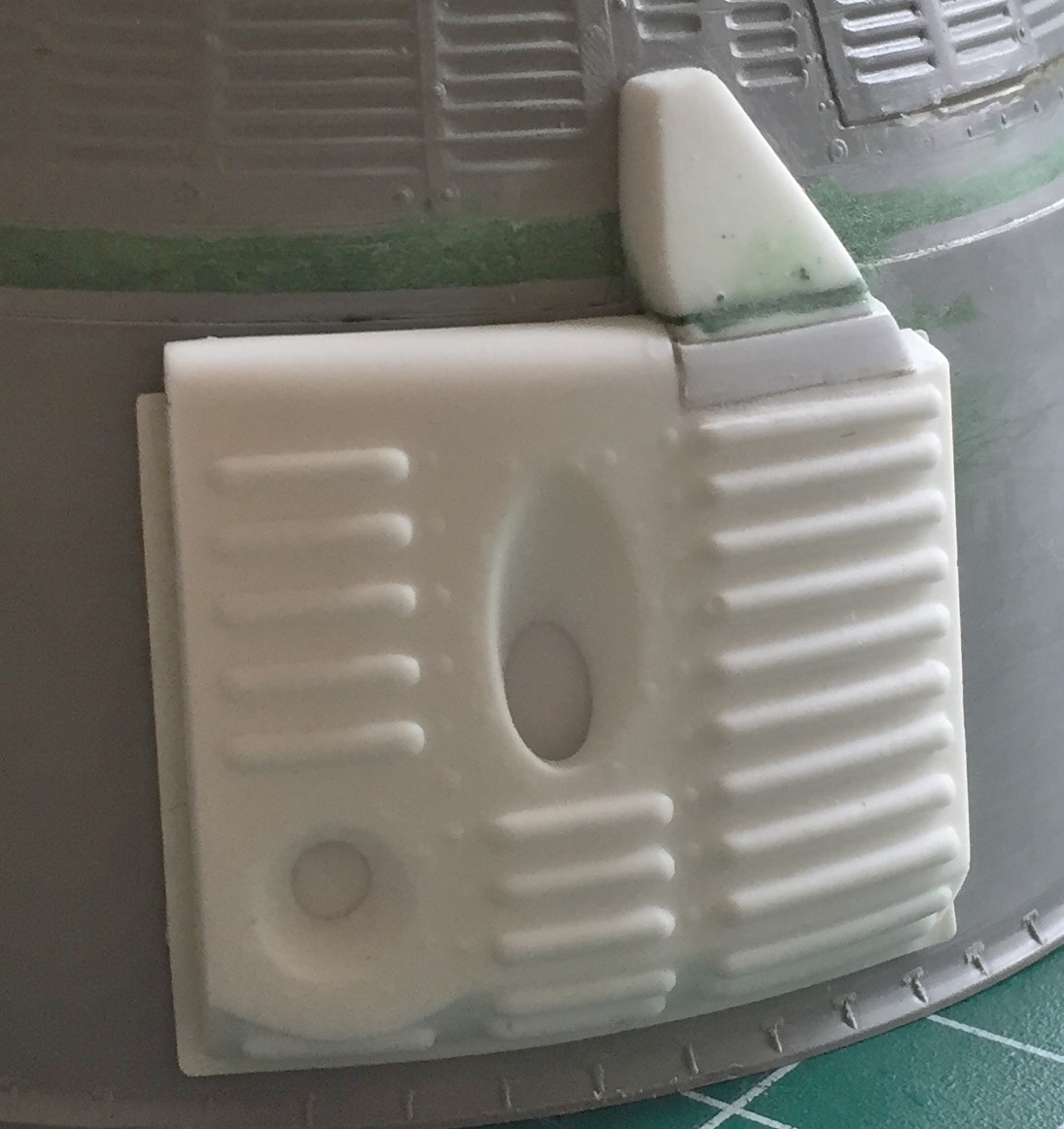
So for everything to be where it’s supposed to be, that gap needed to be filled and puttied:
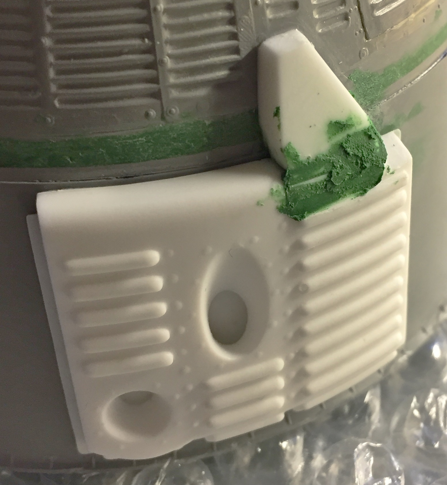
And the same thing had to be done to the other side:
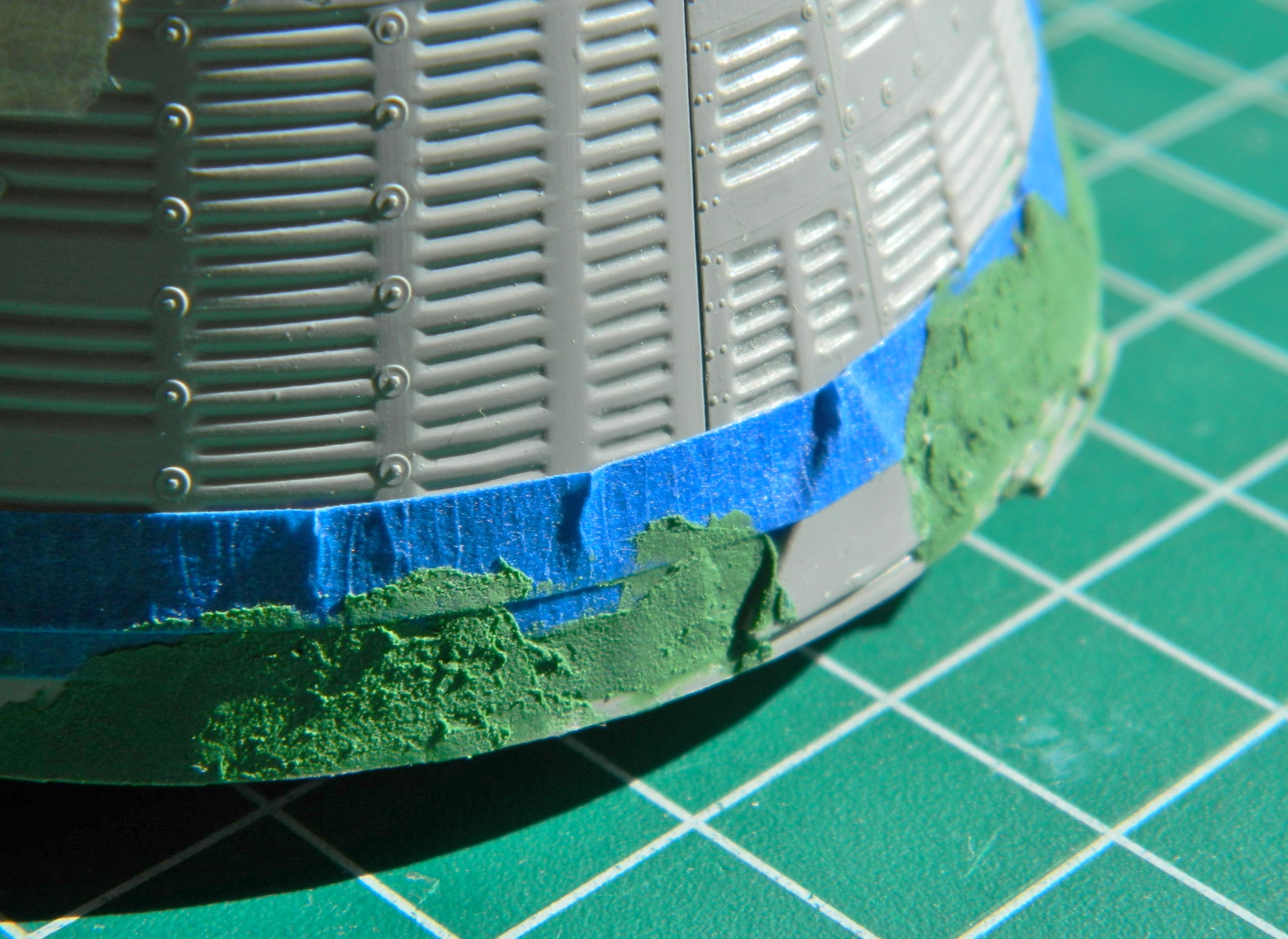
Since I am (too damned slowly) closing in on throwing paint at this, and I CERTAINLY don’t want any over-spray to insinuate itself into the capsule, I needed to close the interior off from that possibility. I closed the hatches as much as they would close and went around the edges of the hatches with white glue, sealing them. Later on the white glue will be removed and the paint touched up, MUCH easier to do on the outside than it would (not) be on the inside:
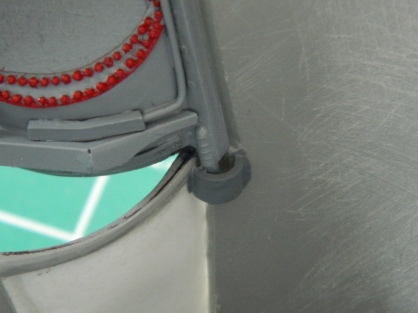
When I put the outer window plastic over the face of the port, I eradicated the surface detail and that got put back using Archer Transfer’s resin rivet decals:

Brain fade is an insidious thing. When it’s happening, it can go completely unnoticed and too often it stays unnoticed. This time I caught my most recent brain fade (I hope) before it was too late to fix. I put one of the OMS packs on backwards! That has to be pried off and reversed. I’m coming to a brand new appreciation of single-edge razor blades. That’s what I used to work under the edge and cut/pry the superglue away to release the module:


At this point I’ve got more experience than I wanted to have adding plastic to fix bubbles. I didn’t see there was an interior bubble on the mounting flange until I popped the module off, so that needed fixing. Once I’d trimmed the plastic to fit, the module was reattached properly:

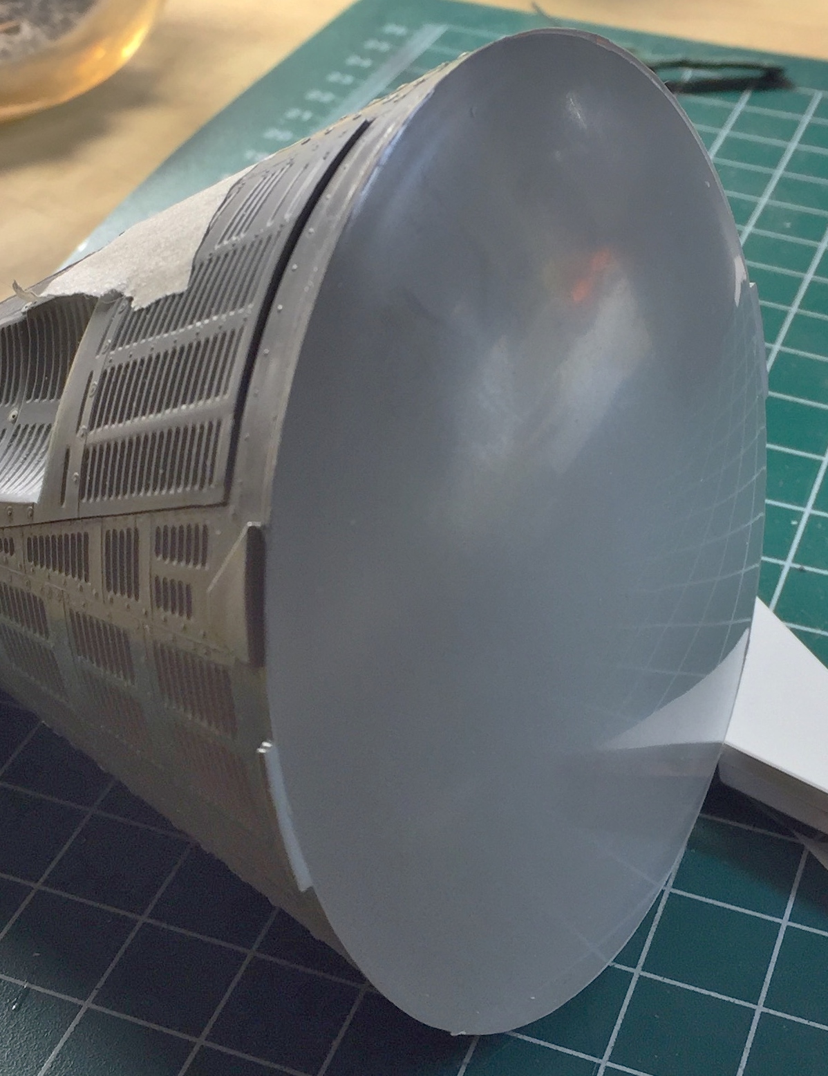
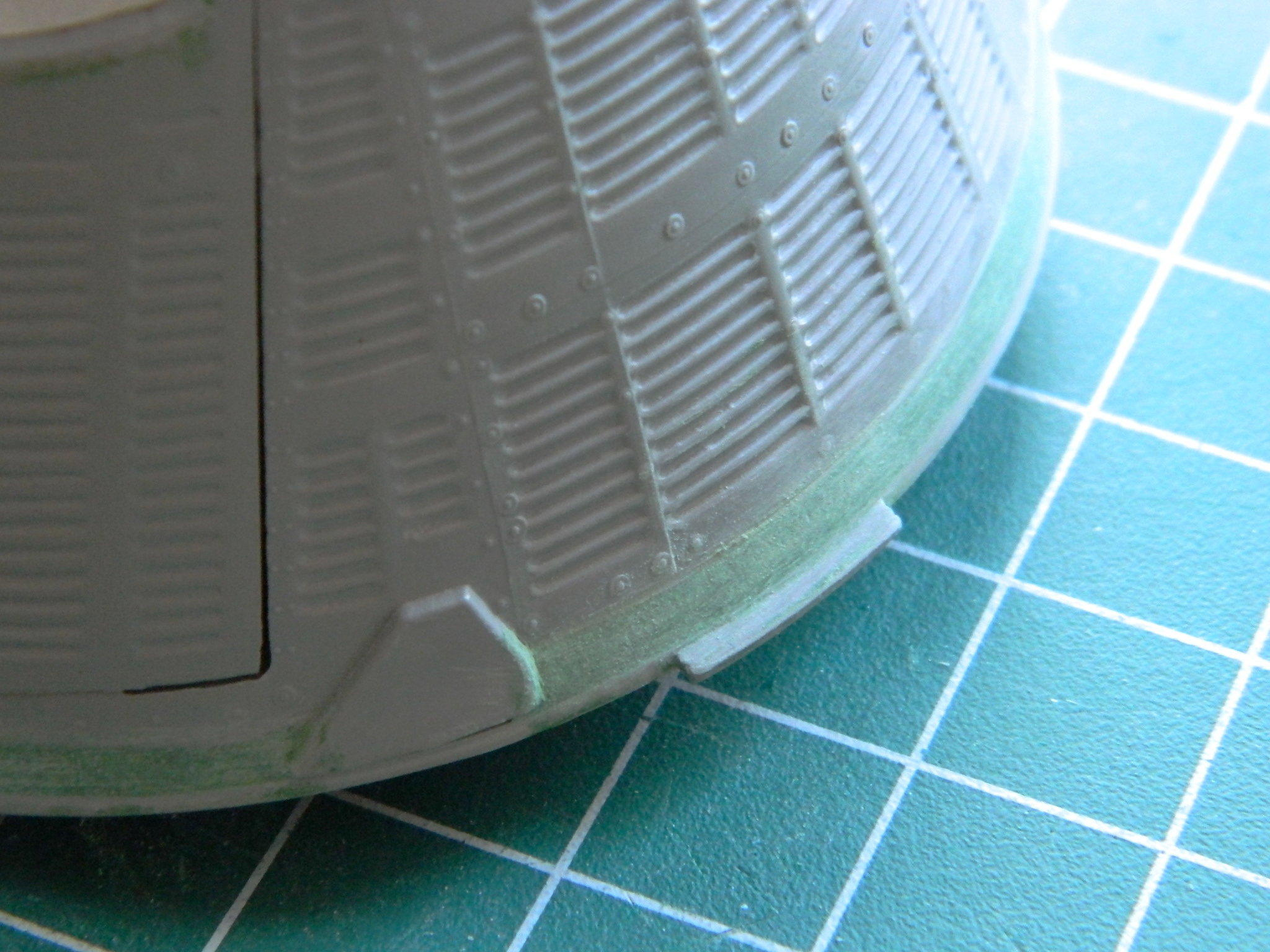
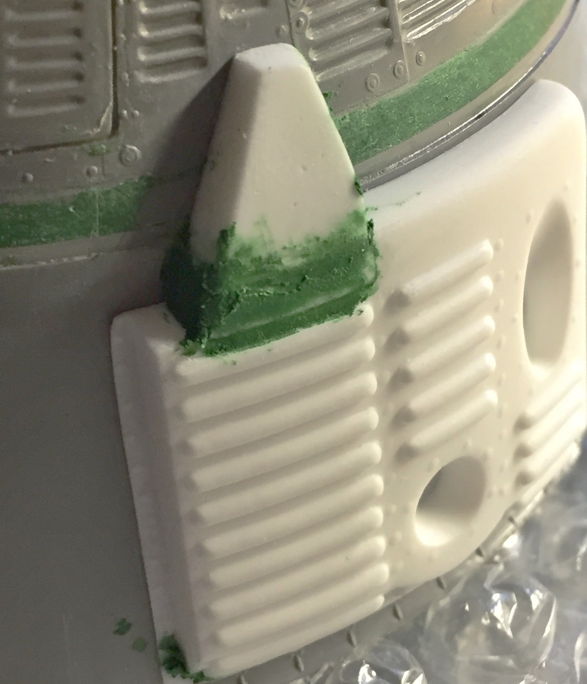
And one last thing (for now…I’m sure there will be others) that I really did not want to do. The fit of the nose cone to the OMS ring was as high as all the other fittings were not. I didn’t want to deal with the shingles that would be destroyed in fixing this fit. Yet I’ve gone to such lengths for other things, and people will probably look closely at that (quoth my Ego), so I don’t want them to wonder why I went to such lengths in other places and overlooked an obvious fit problem. Well, excrement…let’s just fix the sodding thing. I added putty and worked it until the fit was correct:
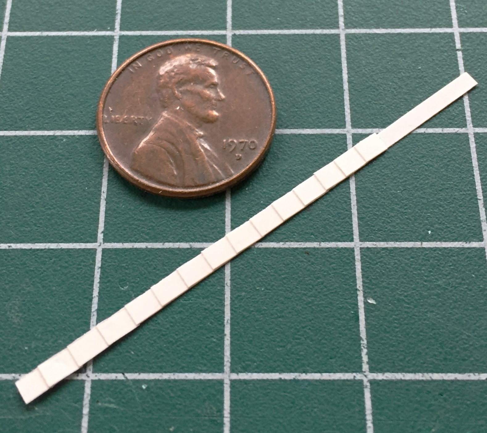
To put the shingles back, I had to make them. A strip of .005″ (.127mm) plastic with more .005″ (.127mm) plastic cut to the dimensions of the existing (and unmolested) shingles had to be made:
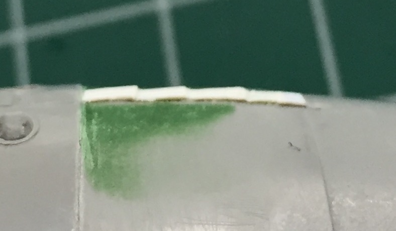
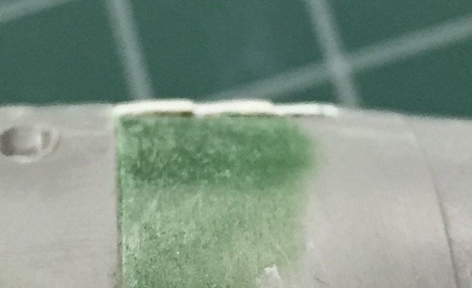
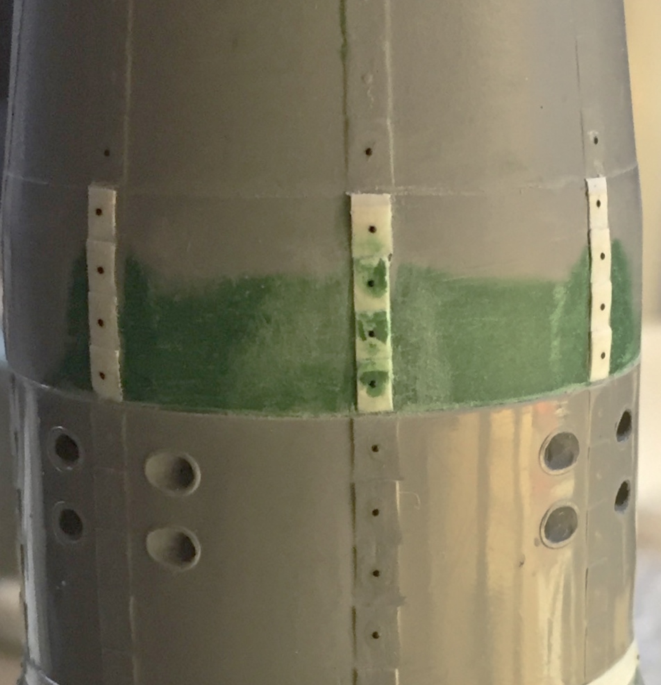
Then the shingles were cut away from the strip and added to the nose. They stuck out too far from the other shingles, and I did not want to replace all the shingles, so those got sanded until they were closer to the correct height (if I sand them any more, they’ll probably vanish). Once done, I added resin rivets:

There’s only one more part to add to the capsule, the horizon sensor (which still needs some work before it’s ready to go on), before it’s ready to paint.
I’m generally not superstitious but Eris and Loki do pay far too much attention to me, so I’m a little trepidatious saying, y’know…I just might, might, MAYbe, have this done in time for the show at the end of April!
