At a certain point (and too often, an uncertain point) I get to the “chicken or the egg, and where do I start” point. I need this to do that, and I need that to do this. To start filling the bays with stuff, it would be handy to have the landing gear, or at least part of the landing gear, constructed. But, to build the landing gear, it would be equally handy to have the landing gear bays filled with stuff.
Hmm… I have a VERY worn 1926 Peace silver dollar in my wallet that I use when I get to a decision that’s evenly (and/or oddly) balanced between two choices; heads I do, tails I don’t. At the “chicken or the egg, and where do I start” point, it’s time to bring out the Morgan. This time, heads meant I start on the landing gear.
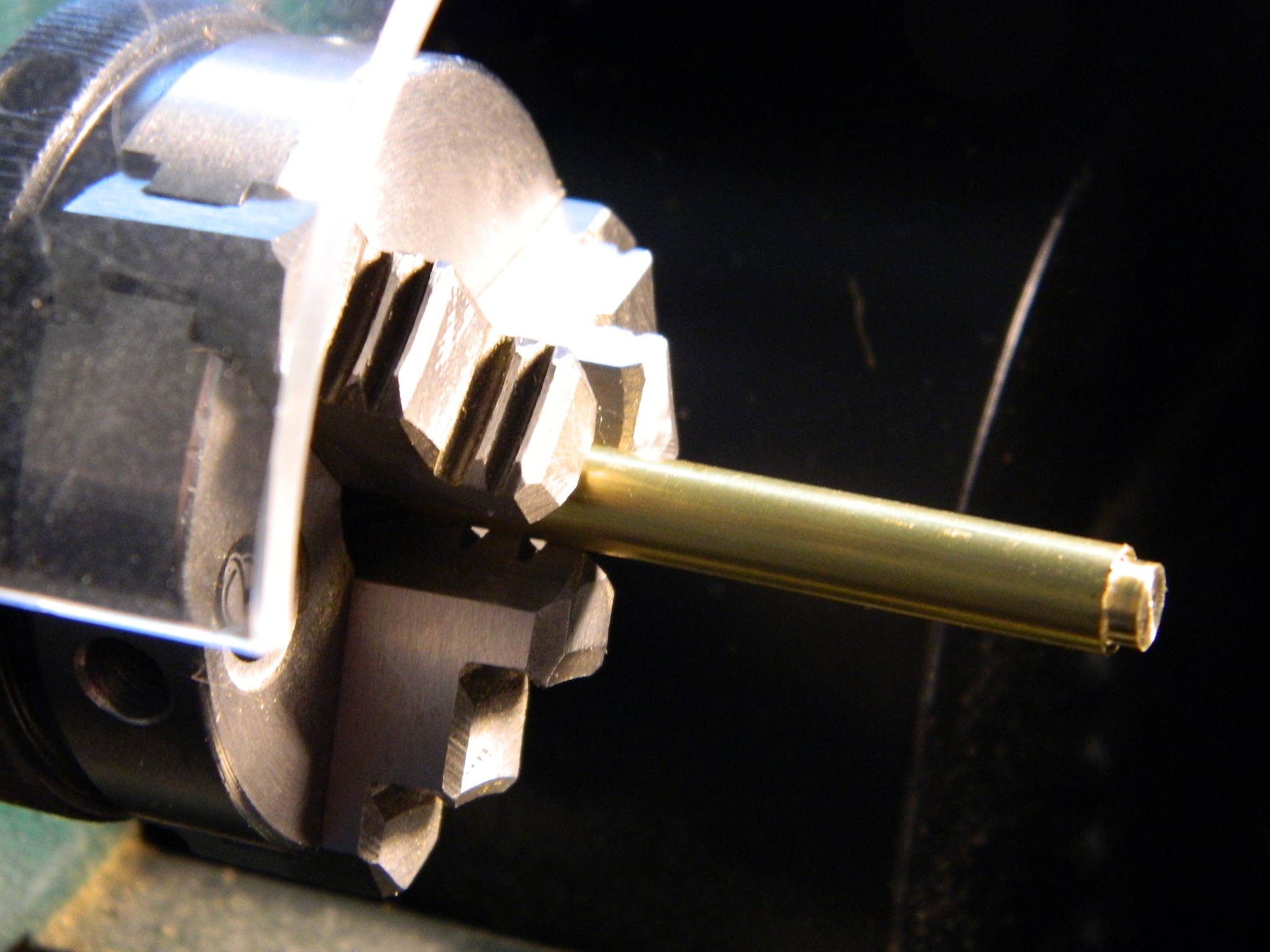
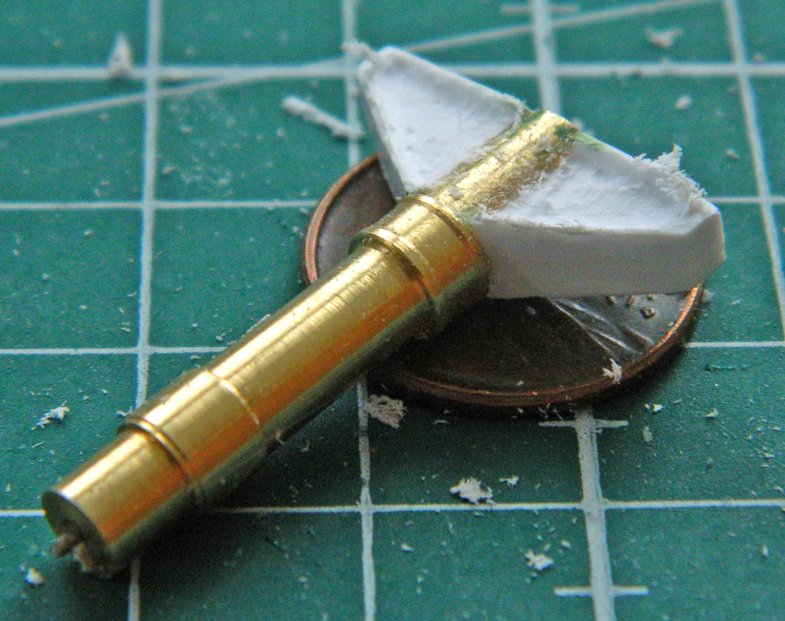
I cut a piece of quarter-inch (6.35mm) brass rod to an approximate length, leaving enough length to get the part as long as I want it and still enable the lathe’s chuck to firmly hold it without having to cut too closely to the chuck’s teeth to pose a hazard:
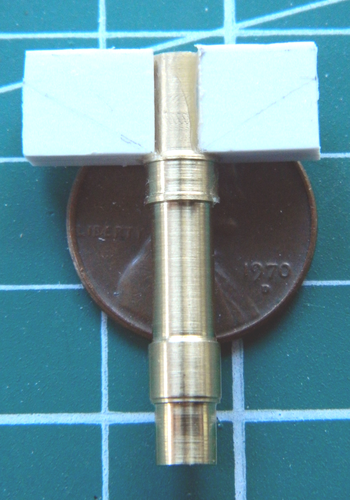
Lots of spinning and cutting as well as center-drilling the end for a pin I’ll need to install later and I ended up with this (which will be cut off at the shoulder on the left…I used the kit’s landing gear struts on all of the landing gear struts to establish the new parts’ overall length):

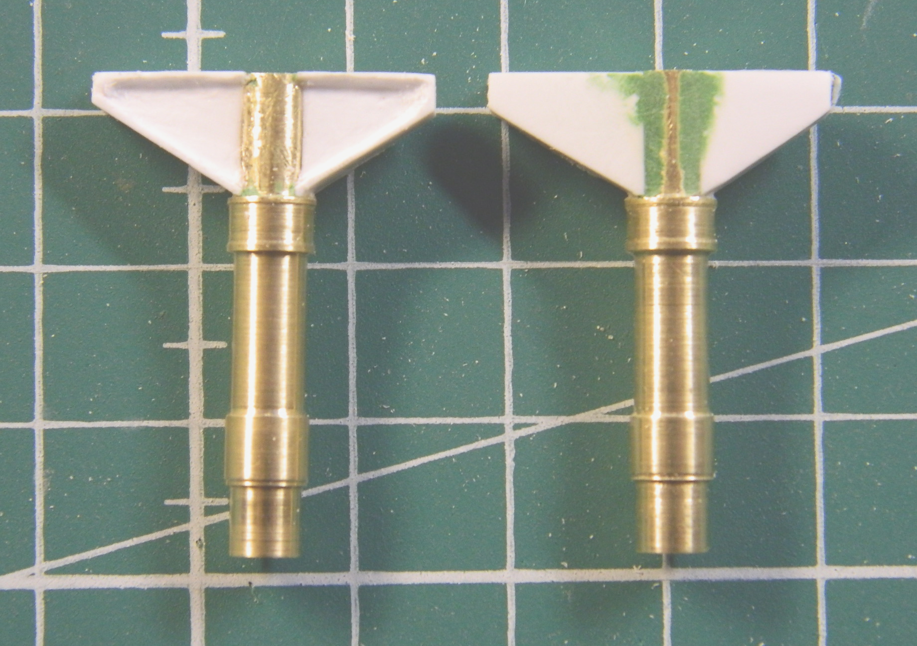
Okay, that’s what I want. Next trick is to do it again…and I did (sorry the photo is blurry…my vision was equally blurry and I didn’t notice at the time):

Originally I had purchased a set of metal landing gear from Scale Aircraft Conversions (#48067). All they do are landing gear sets from what seems to be a lead-based alloy. For a large and heavy model, it seems a good idea. Not faulting their process or business model, what I ended up with were copies of the kit part, only in metal. Great if the parts are accurate to being with…which they aren’t.
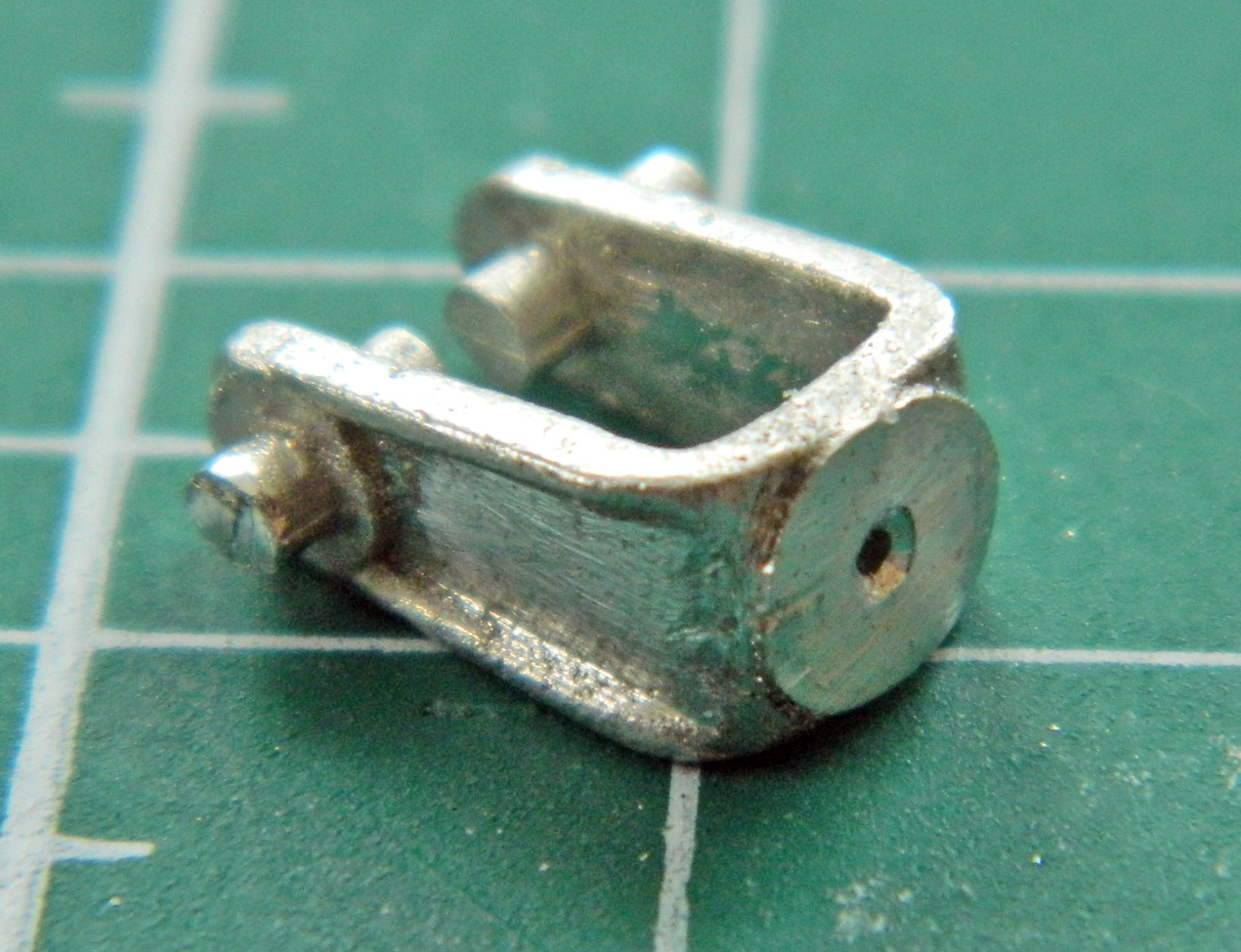
One of the things that have been nagging me is just how am I going to do the yoke where the center tire mounts? Any idea I came up with was either impractical or far too complicated. The idea I went with was the most simple (a concept that I need to keep in the forefront of my mind); cut the yoke off the SAC parts and glue it to the brass struts (that’s why I drilled the struts for pins). The nice thing about a lead-based alloy is that it can be easily cut with a razor saw (there are other benefits as you will see later):

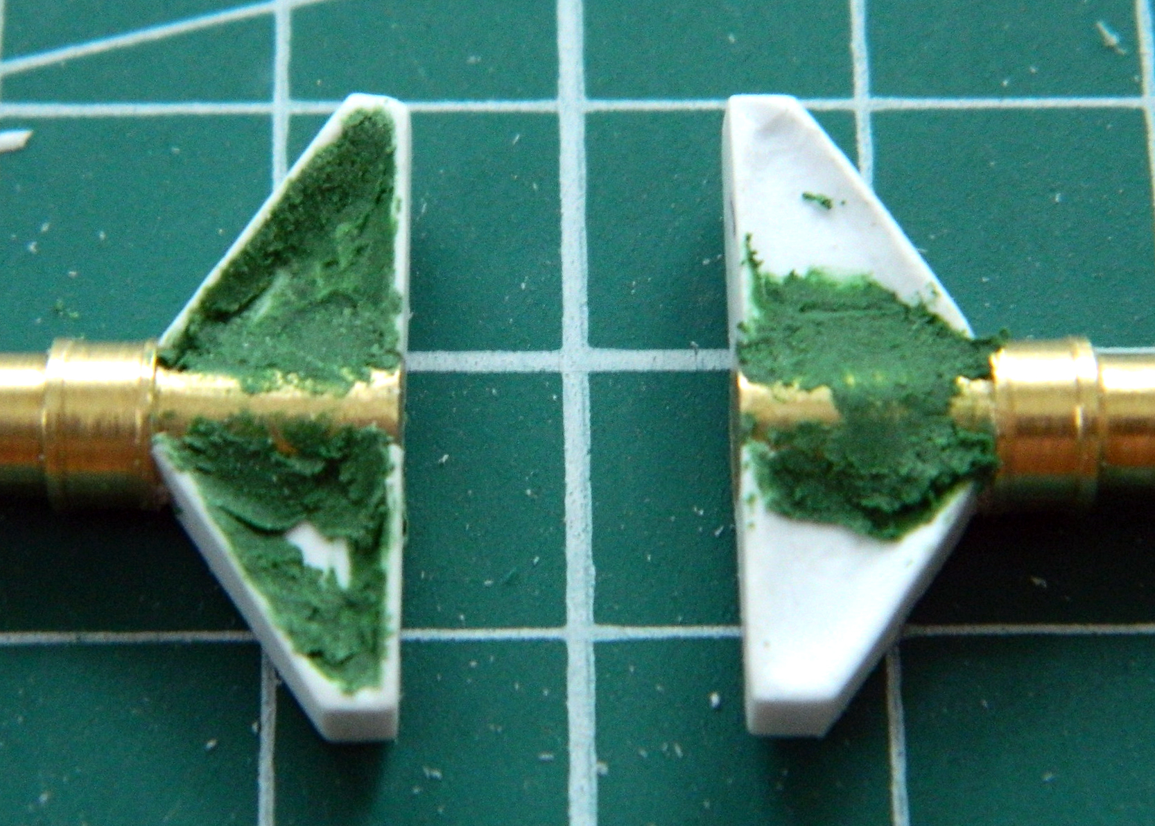
As with the nose gear, the top of the main struts have cast trunnions. As with the nose gear, these have to be built. .080″ (2.032mm) styrene is about half as thin as I needed. I laminated two pieces together, curved the ends where they attach to the strut, and glued them in place (if you look closely, you’ll see the pencil lines where I have to cut away unneeded material):
Once the wings were cut to their basic shape, the inside of them had to be carved out:
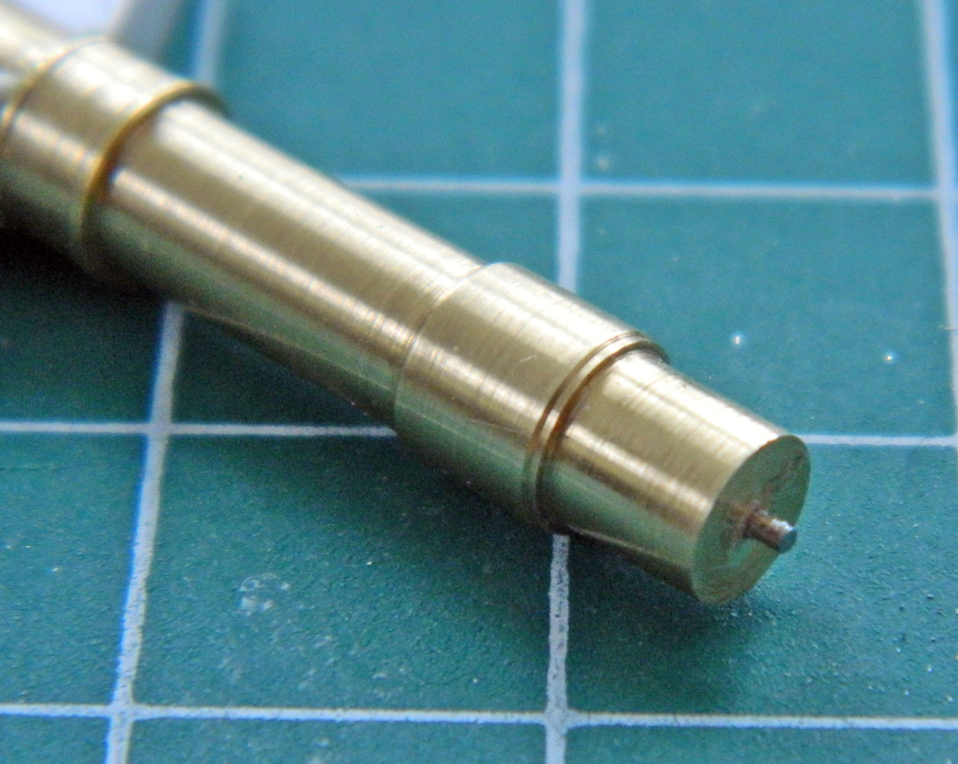
Some carving, some puttying, and I could add the pin. The size of this model called for the use of metal struts and I wanted to use a pin that was also strong. So I used a pin and then trimmed it:

Then there was carving and puttying on the next strut to do:
With the pin in place as the trunnions shaped, I center-drilled the yoke.
A word about that whole “center-drill” thing… It’s a genuine ass pain to do; ONE way to do it correctly, and an infinite amount of ways to get it wrong. Since my eyes (or pretty much any part of my decrepit body) aren’t what they once were, I’ve figured a way around my limitations. I drill the hole the pin will socket into slightly oversized. This way I have a built-in fudge factor in the likely event the hole isn’t PERFECTLY positioned. I countersunk the hole because there’s usually a slight bubble of glue where the pin meets the surface. Countersinking the hole (done at this size by using a larger bit than I need for the hole) allows the two parts to fit FLAT against each other:
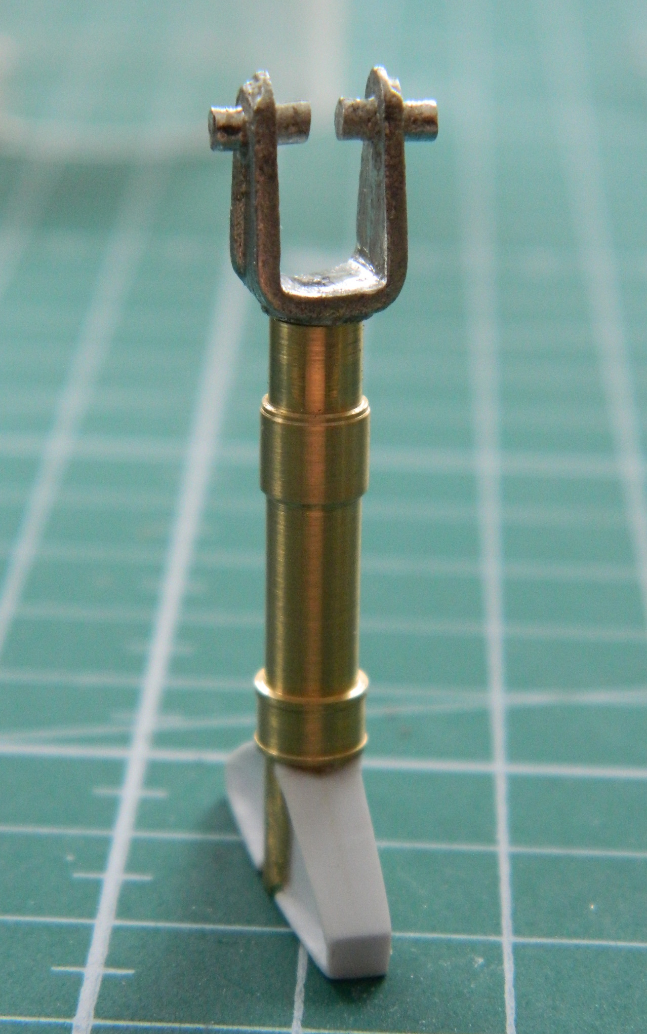
Dry-fitting the strut and yoke show that they do indeed fit snugly. Satisfied with the fit, after this photo was taken, I used 5-minute epoxy (for strength) to join the two parts:
Some putty is needed to create the illusion that the top of the strut is one casting, not a part with two other parts added. I got a little carried away when I carved the one trunnion, so that got puttied while I was at it:
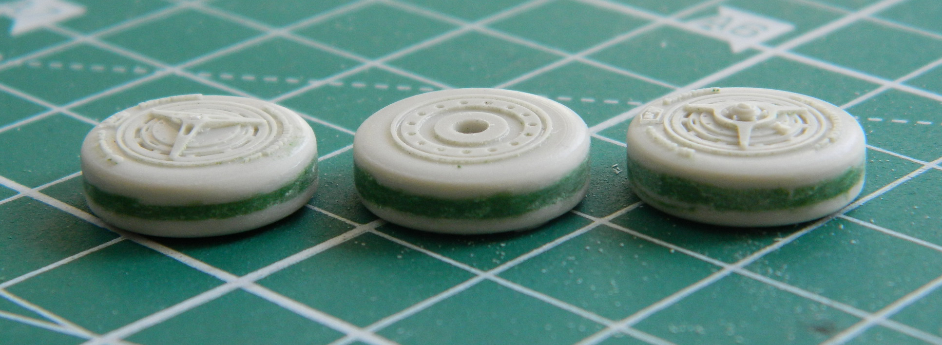
I’m using a set of resin wheels and tires from Fisher Model and Pattern (part #A-4806) for this build. The details of the hubs are far superior to the kit’s “details.” Even as nicely done as they are, they still need some attention. All of my reference photos show that the contact surfaces of the tires are smooth and don’t have the treads Fisher has modeled into the tires. The contact surfaces are also supposed to be slightly convex, not slightly concave:
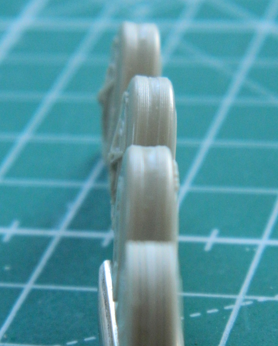
I roughed the surfaces of the tires hoping that this would offer more bite for the putty added to round the contact surfaces. If the putty wouldn’t work, the alternative would be to sand the corners of the tires away completely. Well…it worked, sorta. The putty wasn’t entirely interested in sticking to the resin (yes…I washed the parting agent off). I managed to get the putty to stick by almost sanding the putty down to where I wanted it and then soaked the putty with superglue. Once the superglue cured, I finished sanding to shape and it all worked:
I encountered another problem with the nose wheels/tires. The profile of the tires is definitely rounded, not squared off. Files and sandpaper fixed that problem:

The last modification to the resin parts was to drill out the mounting holes so that they would fit onto the landing gear. The axle stubs of the yokes I’d added to the main struts also had to be trimmed down; initially, they were intended for hollow plastic parts.
With all the tires modified and fit, I wanted to get them under paint. The nose tires were painted with color-corrected Tamiya XF-85 Rubber Black. Then I LIGHTLY misted white onto the contact surface of the tires to replicate dirt and wear:
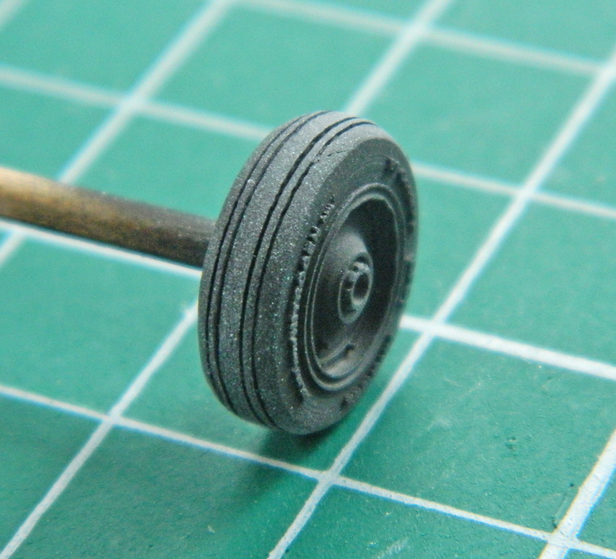
As they were curing, I mixed four parts Tamiya XF-16 Flat Aluminum with one part Tamiya X-18 Semi-Gloss Black. The tires of the Blackbird are impregnated with aluminum powder to facilitate heat dispersion and the flat aluminum alone looked too bright to my eyes so I added the semi-gloss black until it looked correct:

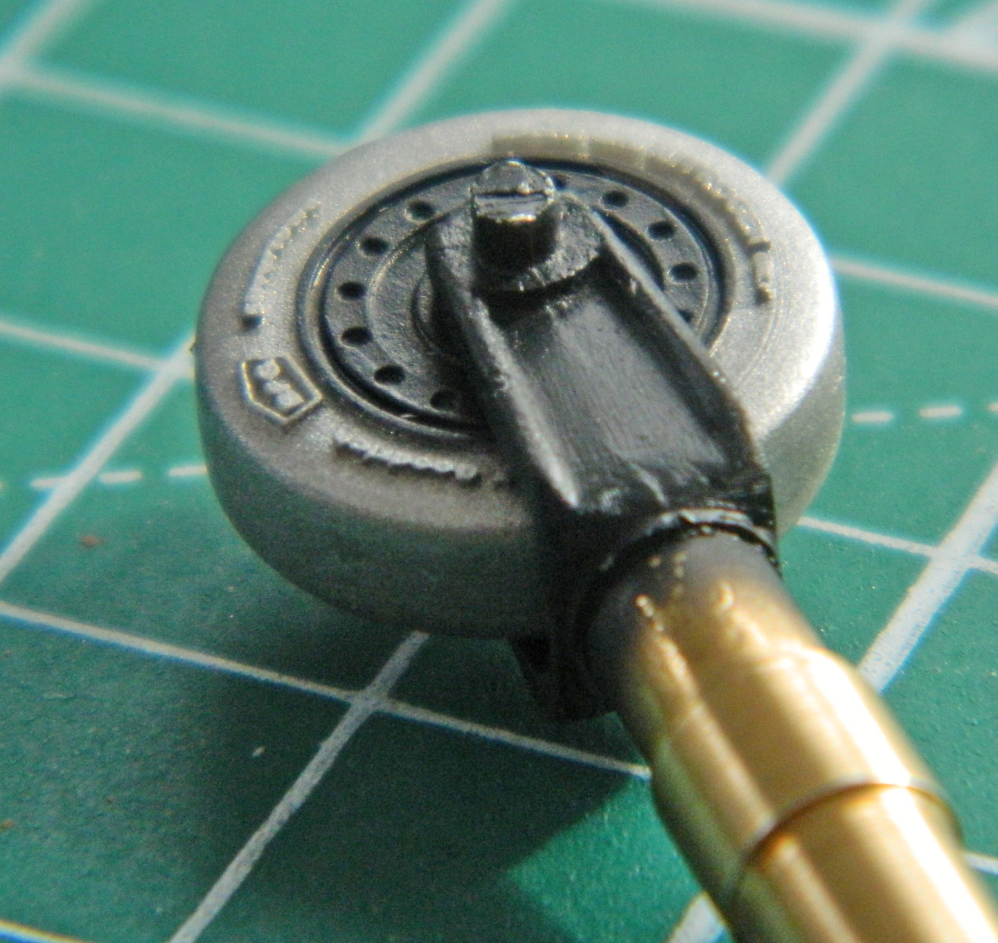
The hubs of all the tires were painted with a color-corrected coat of semi-gloss black. While I had the semi-gloss black in the airbrush, I had to check a couple of things and to do that I hit them with a coat of it. The first thing I wanted to check was how the trunnions turned out. Not quite perfect but certainly within 90-95%. I also have to spread the yokes to get them to accept the center tire (and there’s that other benefit to a lead-based part…it would bend easily). I didn’t know if I could bend them far enough without causing the paint to crack. Ideally, the acrylic paint would be flexible enough, I could get the tires in there, and I wouldn’t have to figure out how to paint the sodding yoke with the tires in place. Luck was with me and it worked:
For the rusted surfaces of the brake disks, I dry-brushed a mixture of two parts Heller Flat Rust (#9113) with Italeri Flat Rust (#4675AP). To my eye, the Heller flat rust was too brown and the Italeri flat rust was too red. The surfaces of the brake disks don’t appear to have an even layer of rust on the surfaces so I used a very small brush and dry-brushed the mixed paint onto the disks:

So…having decided which to start with, I’ve started with it. The next trick is to start making the stuff that goes into the landing gear bays and stuffing them with the stuff.
