Tamiya M4 After-action Report
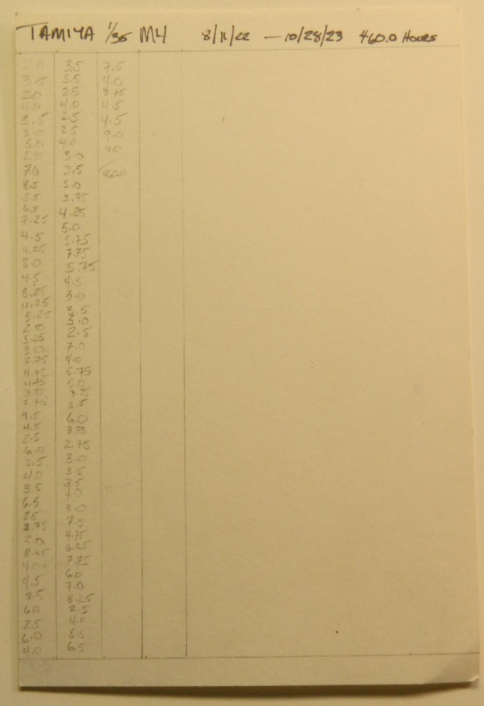
Total time building 460 hours* (of which 36.0 hours was spent crawling around looking for parts that dropped onto the floor).
Begin date November 11, 2022; end date October 28, 2023.
Vendors:
Tamiya
Kit #35190 – M4 Early Production Sherman
CMK
CMK turret set #3027 and inner hull detail set #3026
Tiger Model Direct (TMD)
Set #1236 – M4/M4A1/M4A3 PE Engine Deck Set
Set #1289 – M6 Detailed Periscope and Mount Set
Set #1317 – U.S. Footman Loops Type 3 (Small w/Feet)
Set #1171 – Sherman Return Roller Arm – Straight
Set #1237 – Sherman Ventilators
Set #1086 – M4A2 Rear Armor with Adjustable Idlers (I bought this set just for the adjustable idlers)
Set #1258 – M4 Sherman Grouser Compartment Vent Covers; Factory, Asymmetrical
Set #1176 – VVSS B197681 Intermediate Production Track Return Skid
Set #1251 – Sherman “Slatted V” Siren Set
Set #1232 – Small Hatches (for DML but they can obviously work with a Tamiya hull with some fitting
MiniArt
Set #35321 – Continental R975 Engine
Panda Plastics
Set #Worn T48 Rubber Chevron
Archer Transfers
Set #AR35273 – Pin-Ups
Set #AR35209B – Gauges and Interior Stencils (unfortunately dry-transfers are no longer available from any vendor…the last company that produced the chemicals to manufacture dry-transfers has closed and this handy modeler’s resource is as gone as my hairline is)
M&Models
Set #RB082 – .30 Caliber Barrels, turned brass
Tamiya
Turned brass 75mm ammo set (sorry, I lost the packaging and don’t have the item number)
Squadron
Set # SQAA35002 – Resin .30 caliber ammo cans
Resicast
Set #35.226 – Super detailed cupola for Sherman tank
Asuka Model
Set #35-L9 – Browning M2 Machine Gun Set B with cradle
Lots of solder, wire, lead foil, paint (five different manufacturers), and sprue
My opinion
I used Tamiya’s kit because most of the kit would not be used. It’s a basic kit, no sponsons, fins instead of grab handles, recessed welding beads (I’ve found that the best thing that Vallejo’s 100% Acrylic Resin Plastic Putty, item #70.401, is good for is replacing or making welding beads…the tip is fine and with minimal practice allows for the rippled effect of a bead of weld), all the things Tamiya was known for 30-40 years ago. Research showed me that the tank that Tamiya used as their source was an ALCO-produced Sherman. The ALCO tanks had a unique casting where the bow machine gun mounted; it came to more of a peak than the constant-radius mounts used by other manufacturers, so I tried to do all detailing in that style. I did use the kit’s bogies (accurized and modified using skull-sweat and TMD parts), road and sprocket wheels, and idler wheels which I detailed a bit. I didn’t have to cut the engine covers off because they were molded separately. I stuffed that hole with some kitbashed parts from MiniArt’s M3 Lee using their bottom and sides of the engine bay. Since the front engine bulkhead wouldn’t really be seen very clearly, I used TWS’s bulkhead from their R975 resin set. It took some (frequent) judicial trimming to get the engine to fit and the end result was rather accurate. It just fit.
One thing about the CMK interior set was that the directions regarding the location of the interior sponson boxes is not accurate. If those parts are installed as directed, you will encounter fit problems when you try to stuff the turret basket (preferably attached to the turret) into what you thought was the space for it. It’s almost the space for it. Getting the basket to fit (thereby allowing the turret to settle down correctly) is a bitch if everything has been installed, painted, and the upper hull on. It can be done but you won’t enjoy the process!
Once again, Panda Plastics did not disappoint. Their worn T48 track shoes fit perfectly around the kit’s drive sprocket once the upper, inner, edges of the shoes are slightly radiused (rounded off for you non-engineers).
This was my first time using Asuka’s .50 cal set and I really, really, liked it. Enough parts are supplied to build an early or late mount and more than enough scale ammo belts. If you want to do a diorama of the M2 machine gun being serviced, this is a good starting point. You’ll just need to scratch out the inner details of the bolt area. I’ll be using this set again!
The TMD PE set was decent, particularly for the diamond-patterned sponson vent screens. But if you want to use the light guards, don’t. They’re FAR too thin. Instead, use them as templates to scribe .010″ (.254mm) parts instead…you’ll be much happier with the outcome and with the .010″ (.254mm) thickness they’re a MUCH easier to work with and substantially less fragile.
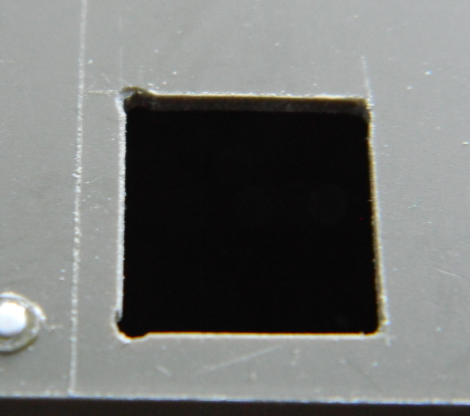
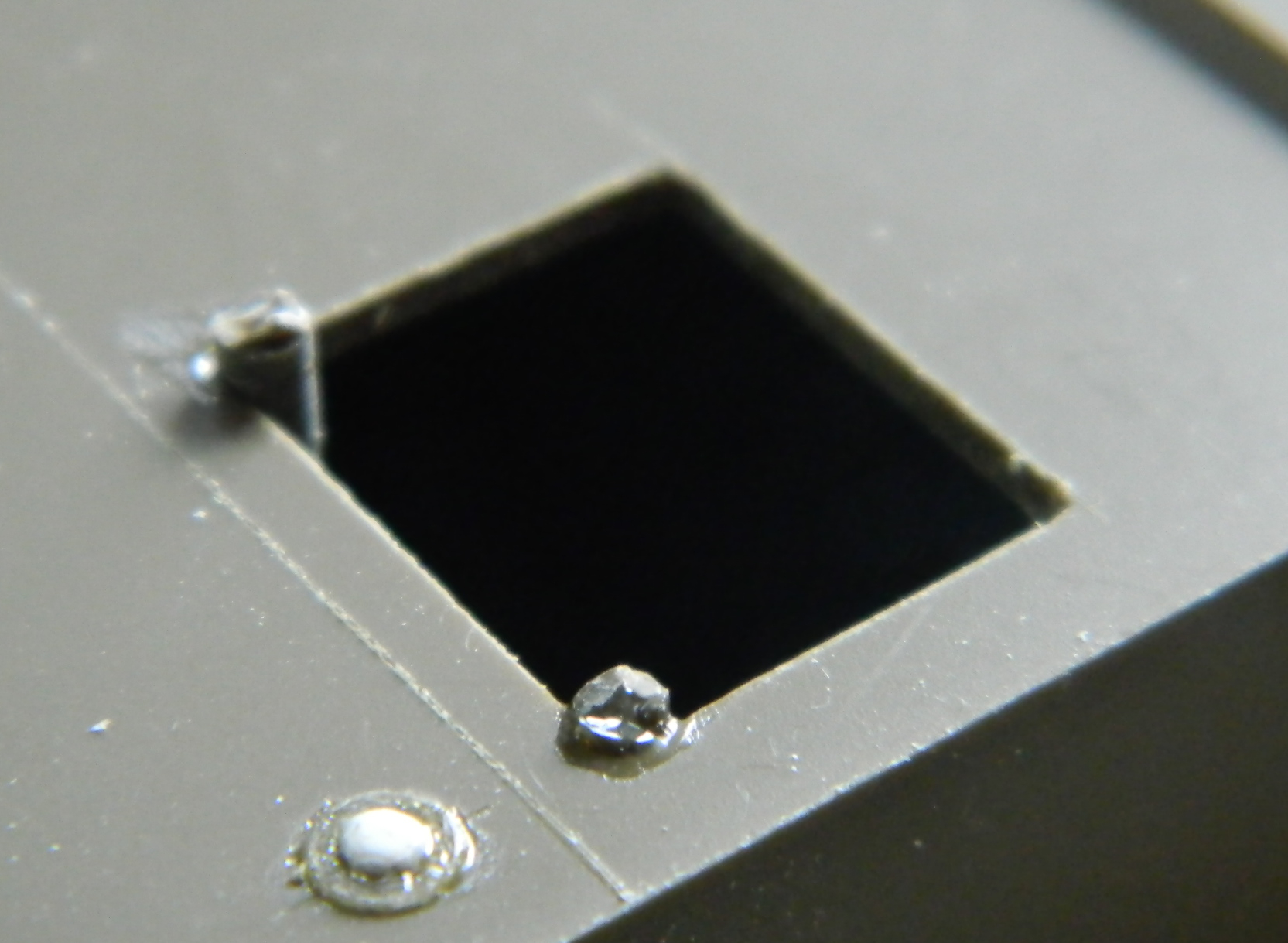
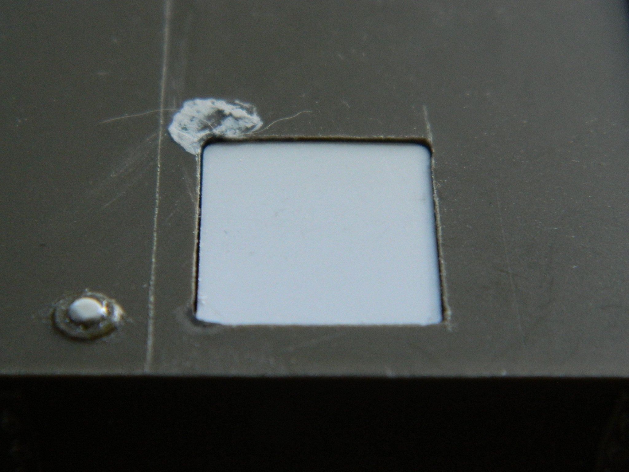
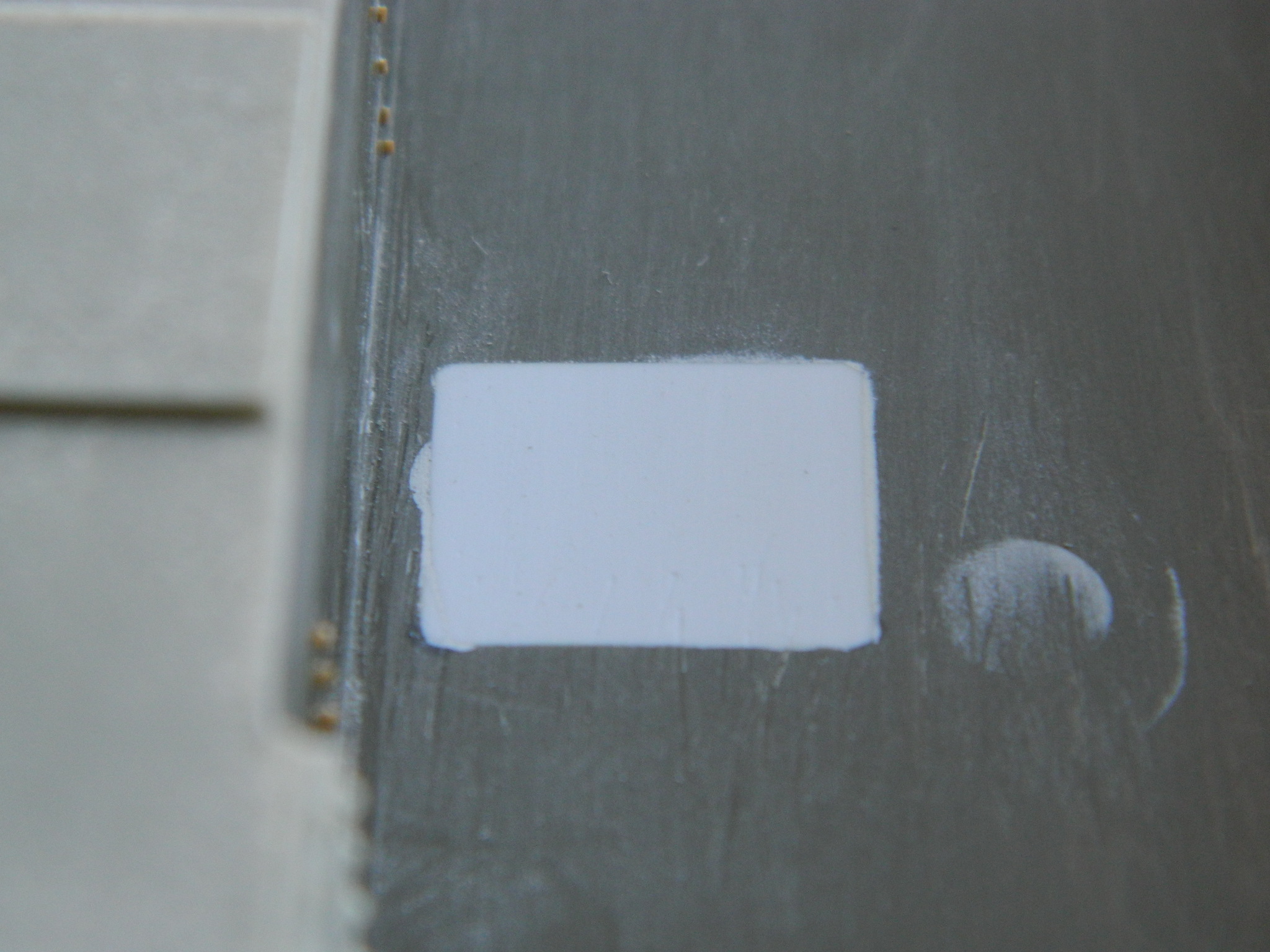
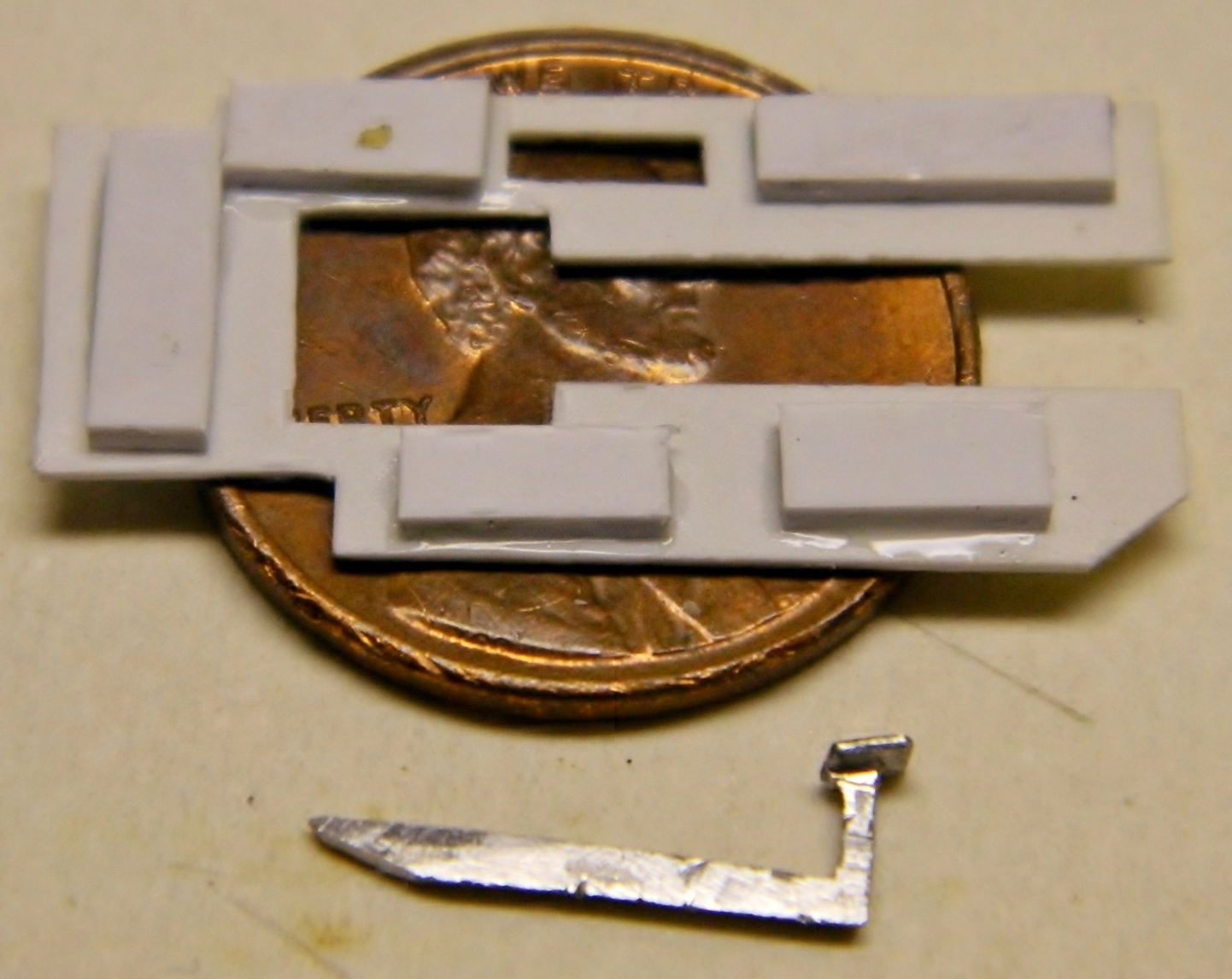
*And now for about the only part of this build that was disappointing and not worth the time and effort to do. Clear panels.
I knew at the outset that putting clear sections to this model was a gimmick. I was hoping it would be a good gimmick but my hopes were left unrealized. Anybody who’s had to deal with clear styrene, and wants to keep it clear, knows how delicate their surfaces are…and that was for the “easy” part, the flat surface of the upper hull’s side. The clear section for the turret was a small section of a clear resin casting. The reason it was a section wedded to the opaque styrene turret was because NO tape I had would stick to the resin snugly and well enough to just mask a section off. The resin was also much thicker than the turret wall it was being inserted into so I had to file it to thickness. Not being completely insane, I did all thickness adjusting from the outside and I am very glad I did. LOTS of filing, sanding, polishing, and many visits back to that tedious well! Once I had both the inner and outer surfaces smooth enough to be clear, I discovered how optical lenses are made! The curvature of the inside of the clear resin plug was not at all parallel to the outer curvature which resulted in a lens and less (as in, not at all) like a window to view the interior bits. As a result, not a great deal can be seen through it and had The Coin come up tails, I would just have painted over it and left it opaque. Being simply flat, the side clear panel didn’t have that problem. With the efficacy of hindsight, I should have realized that the INside of a tank is full of stuff. All that stuff doesn’t really allow much of what’s in there to be seen.
Lesson learned and I highly doubt I’ll revisit this gimmick again.
As ever when adding a plethora of parts to a model that wasn’t intended to have that plethora, there was much fitting, refitting, and colorful invective. Had I not added the gimmick of clear panels I could have probably knocked 60-80 hours off the total time spent. My intent was to model a tank of the 3rd Armor Division, 32 Armored Battalion, which landed after D-Day on June 9 while it was getting kitted up for Operation Cobra, the breakout from the beachhead.
I’m pleased with how it turned out, clear panels excepted.
M4 (Tamiya) Build #3 – Assembling Bits for the Lower Hull Continues and I Ponder Tamiya’s Willingness to Utterly Ignore the Underside of Things
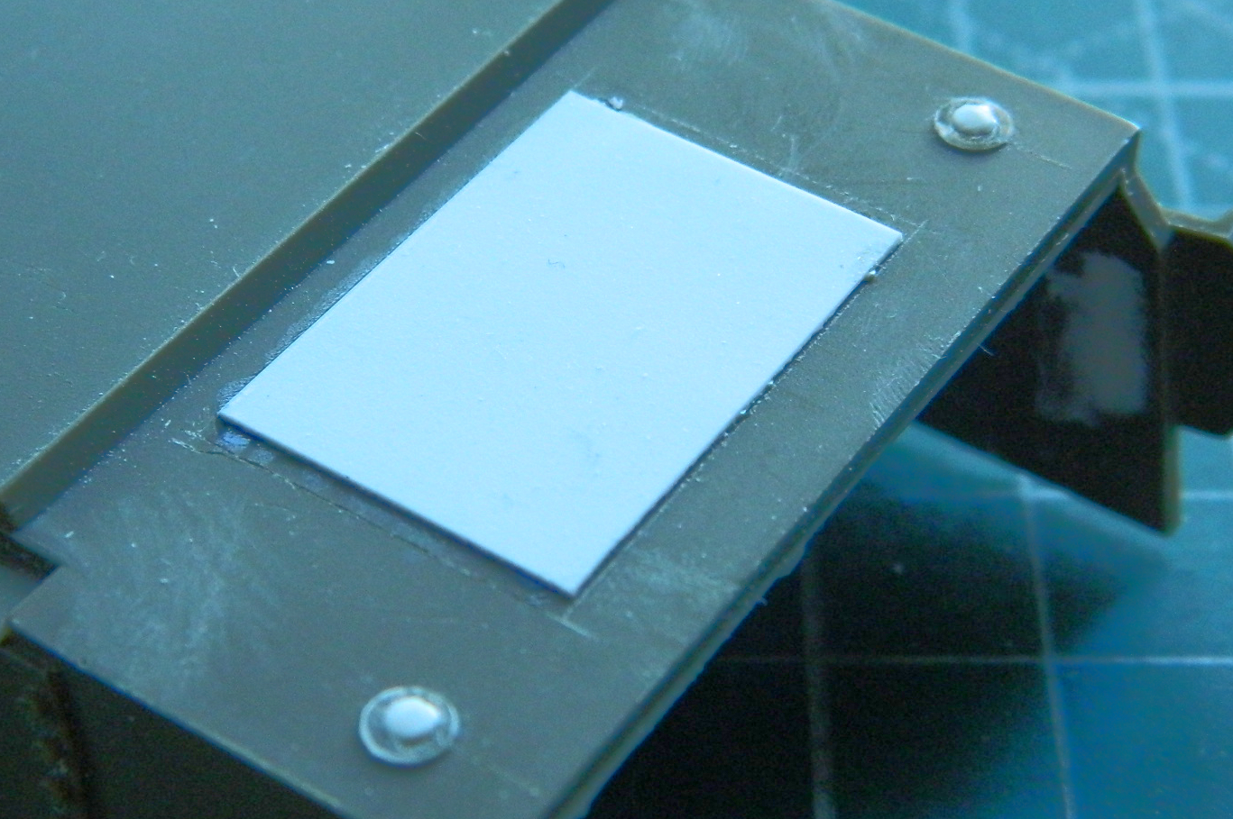
Where the AM sponsons attached was treated with 3M’s Acrylic Putty (because this was during Tamiya’s “Nobody will ever see under here” phase and didn’t bother to include sponson bottoms with the kit). The sponsons were welded and I’ve not seen any seam here so that gets puttied:

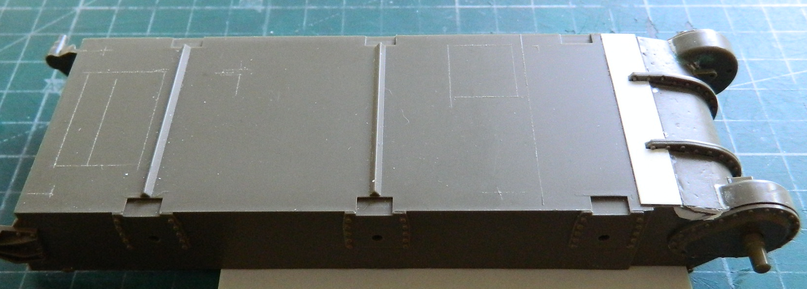
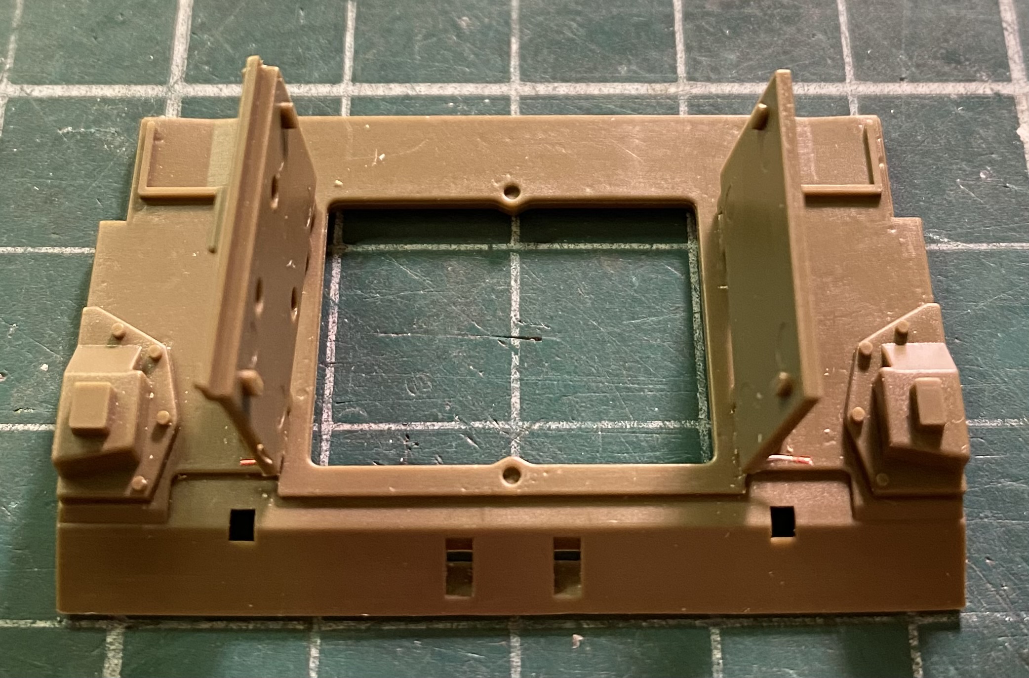
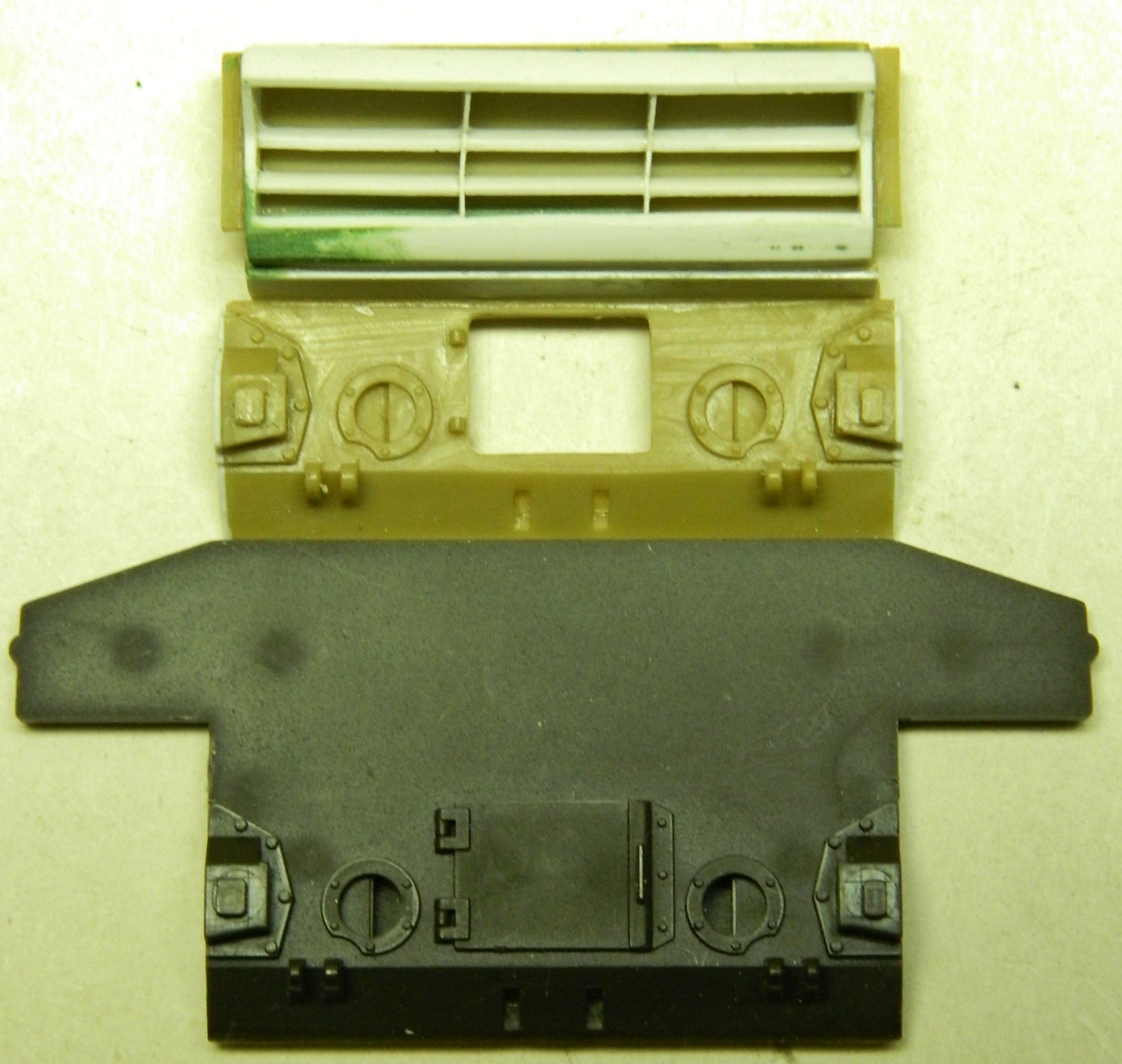
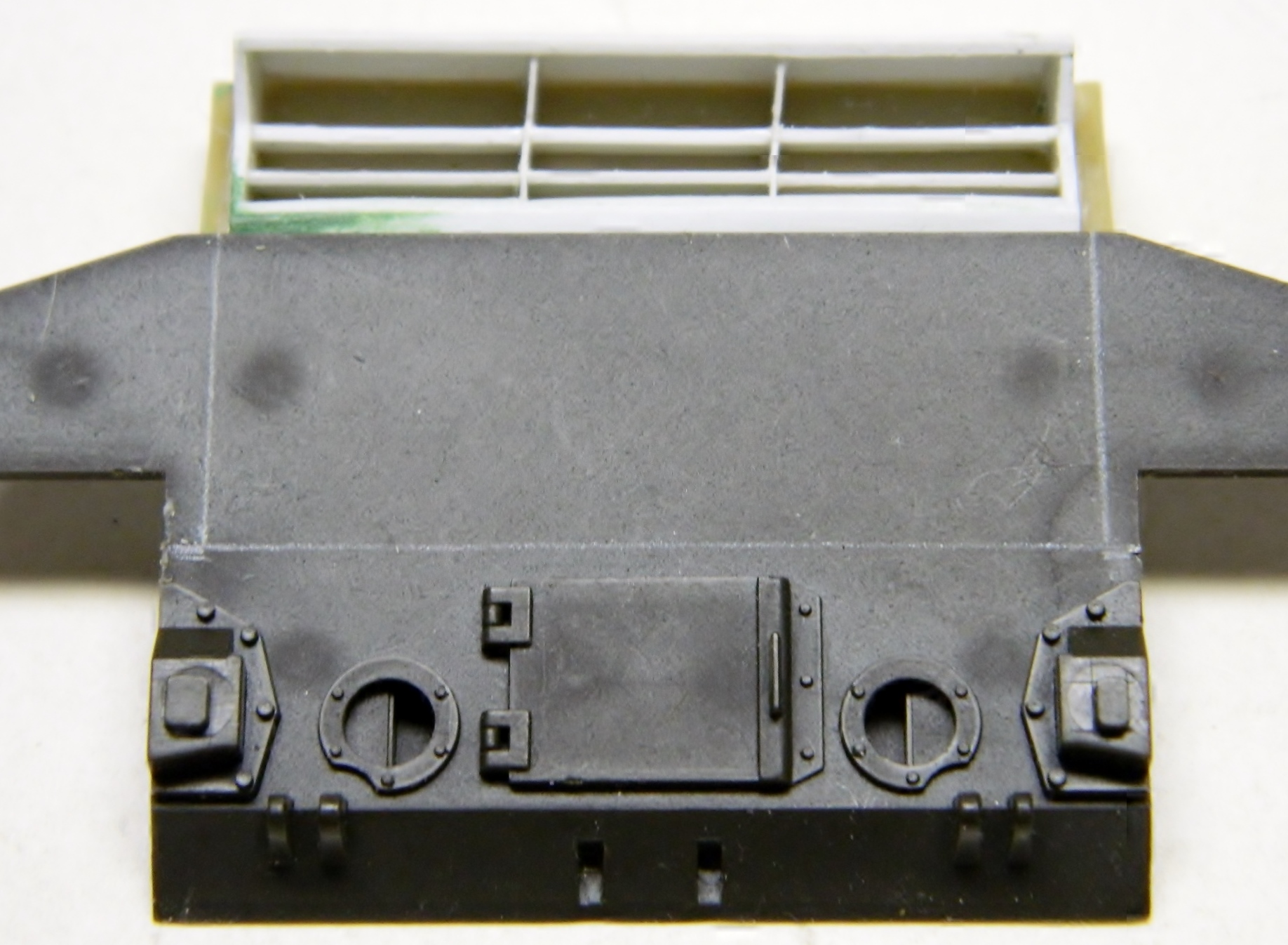
And Tamiya’s utter disregard for anything underneath the model continues to…well…anything underneath the model. Asuka has a good reputation for accuracy and detail (among other traits) so I took one of their DV (Direct Vision…Shermans originally came out of the factory with vision slits for both driver and co-driver) Shermans off the shelf and used the underside of that kit as my source for details and measurements, transferring locations from Asuka who has them onto Tamiya who does not. I know…it looks like the Asuka hull bottom is much shorter but that’s an illusion. The Asuka bottom is a flat piece without sides and it’s far enough from the camera lens to create that illusion. I used a divider (like a compass but with two steel points instead of one steel point and pencil lead) to mark where things are going to go:

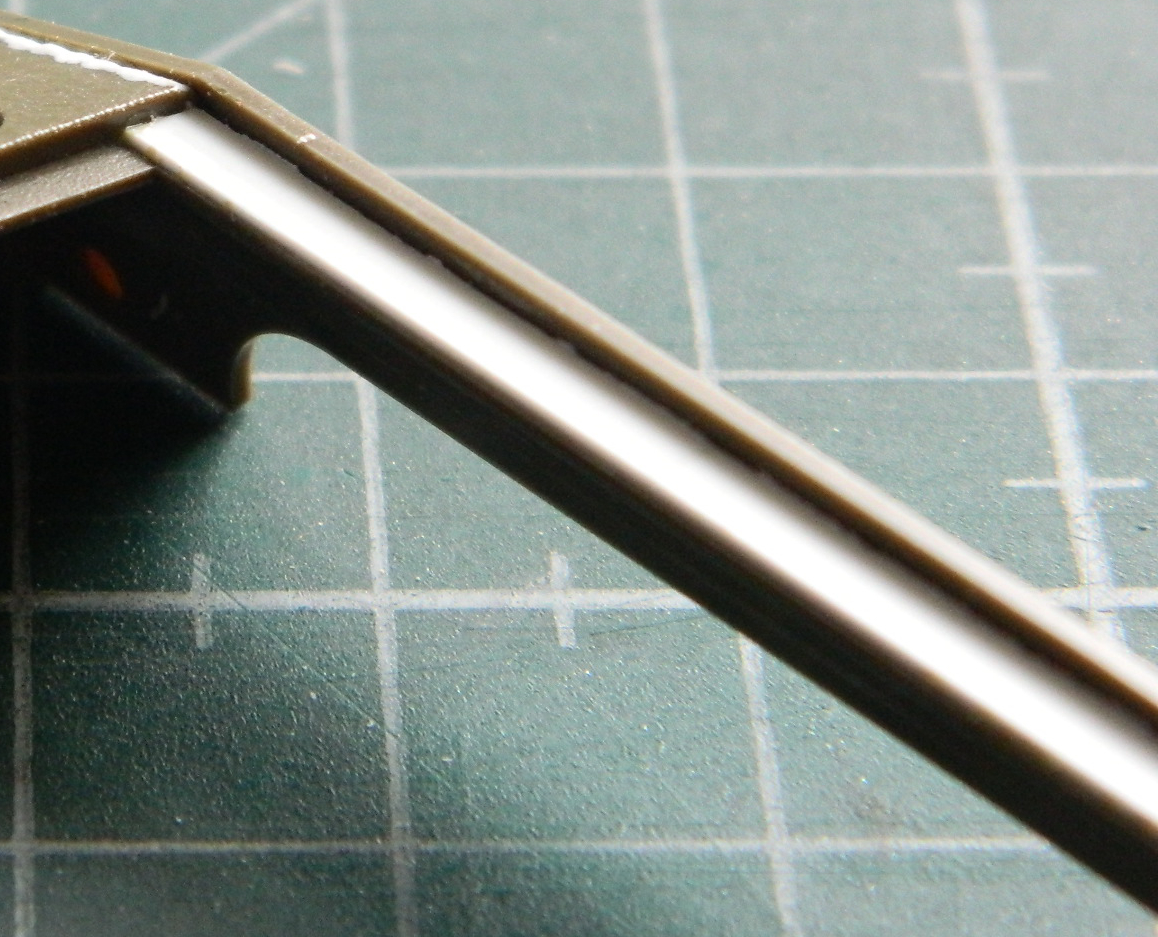
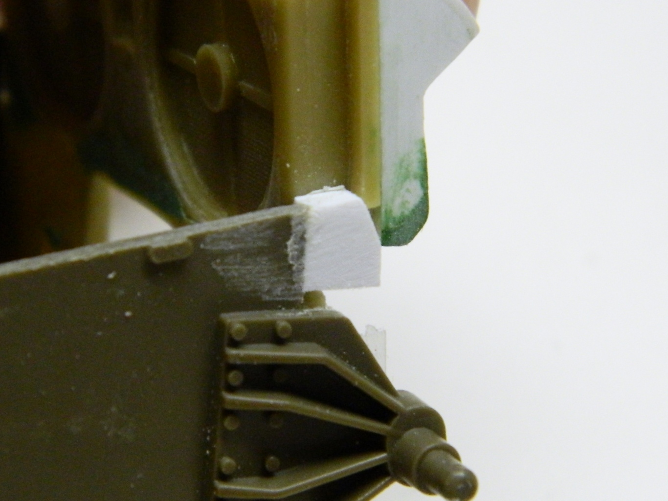
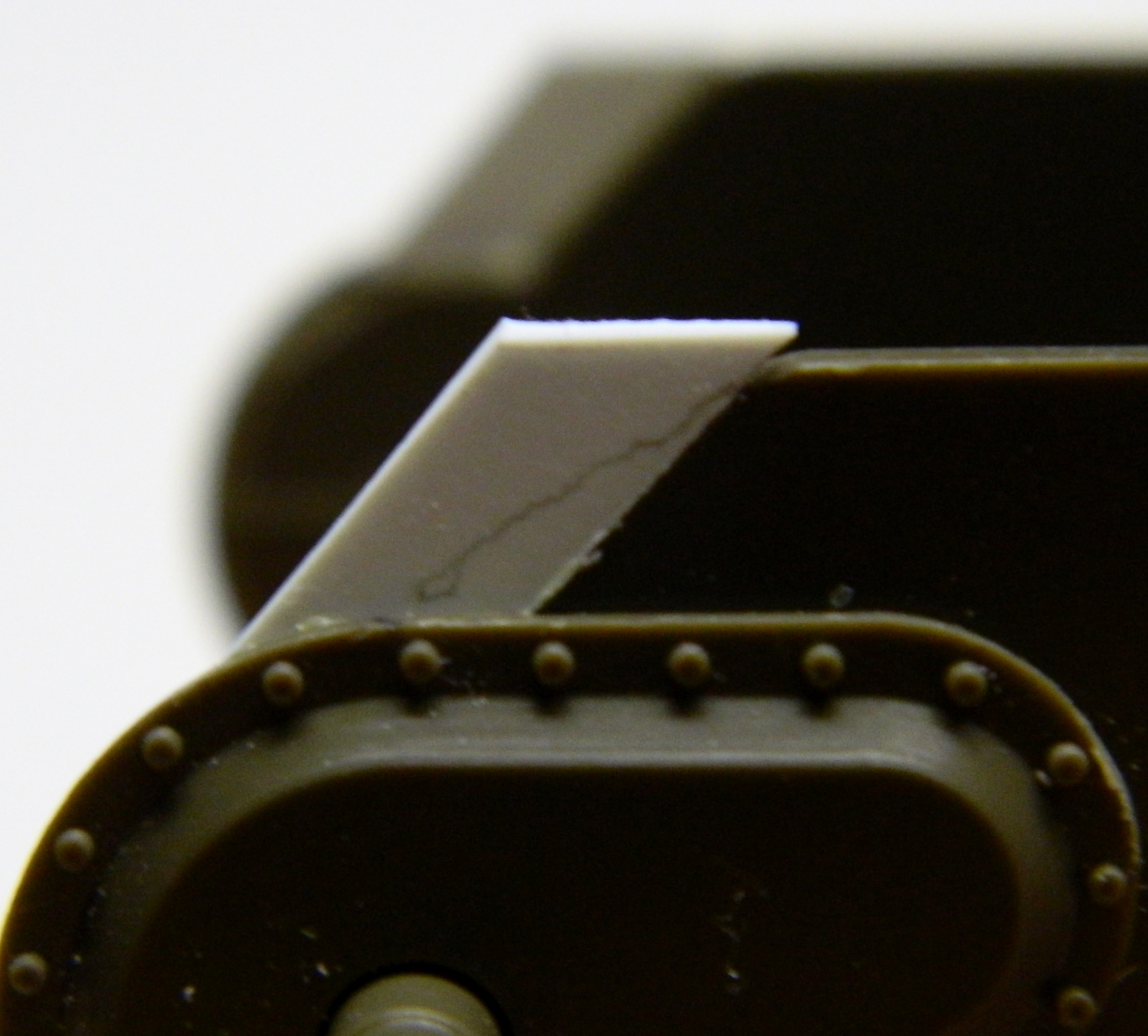
Tamiya ends the differential cover too soon at the underside. I extended the underside of it using .020″ (.508mm) flat styrene. Once the glue sets up completely I’ll fair the forward edge the forward edge of the plastic I just added to blend it with the differential cover:
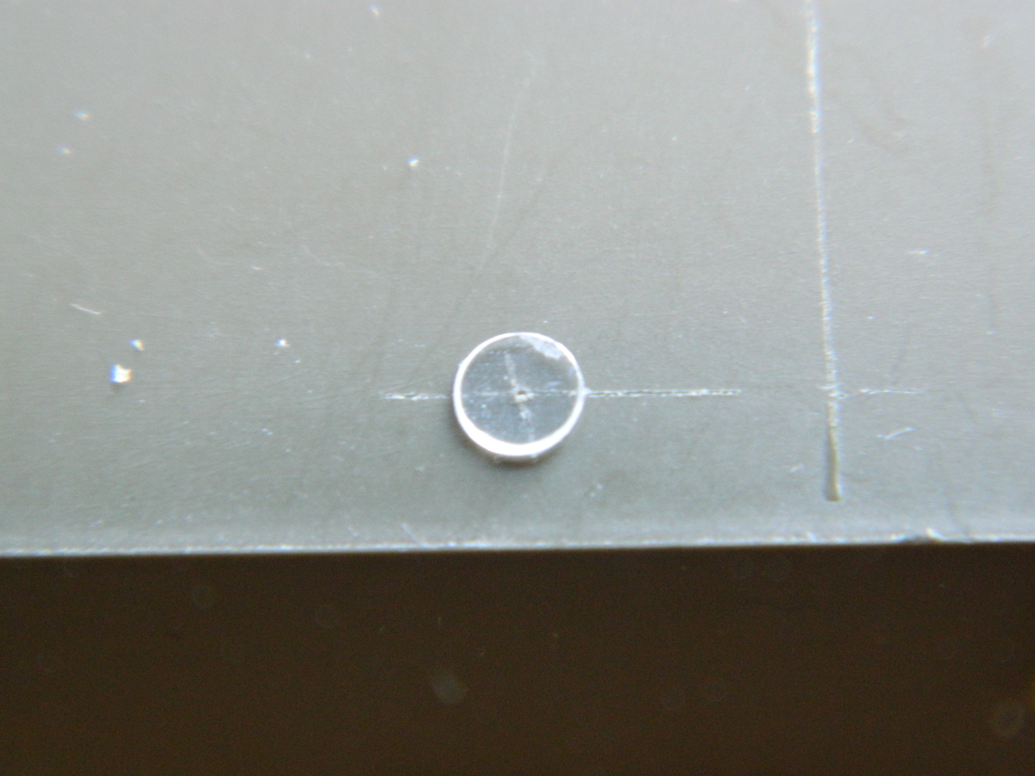
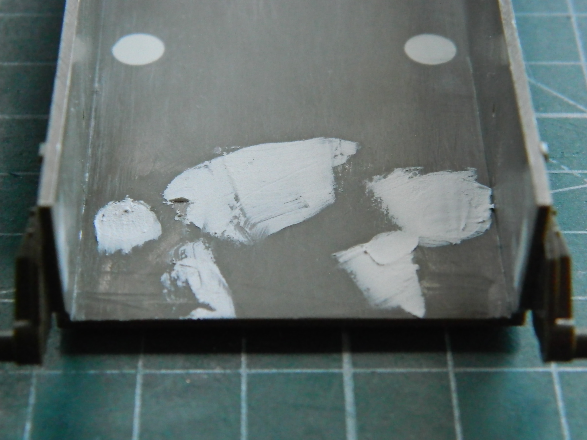
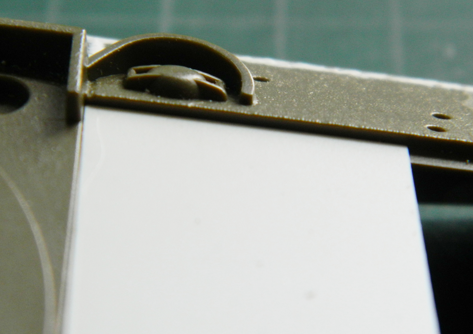
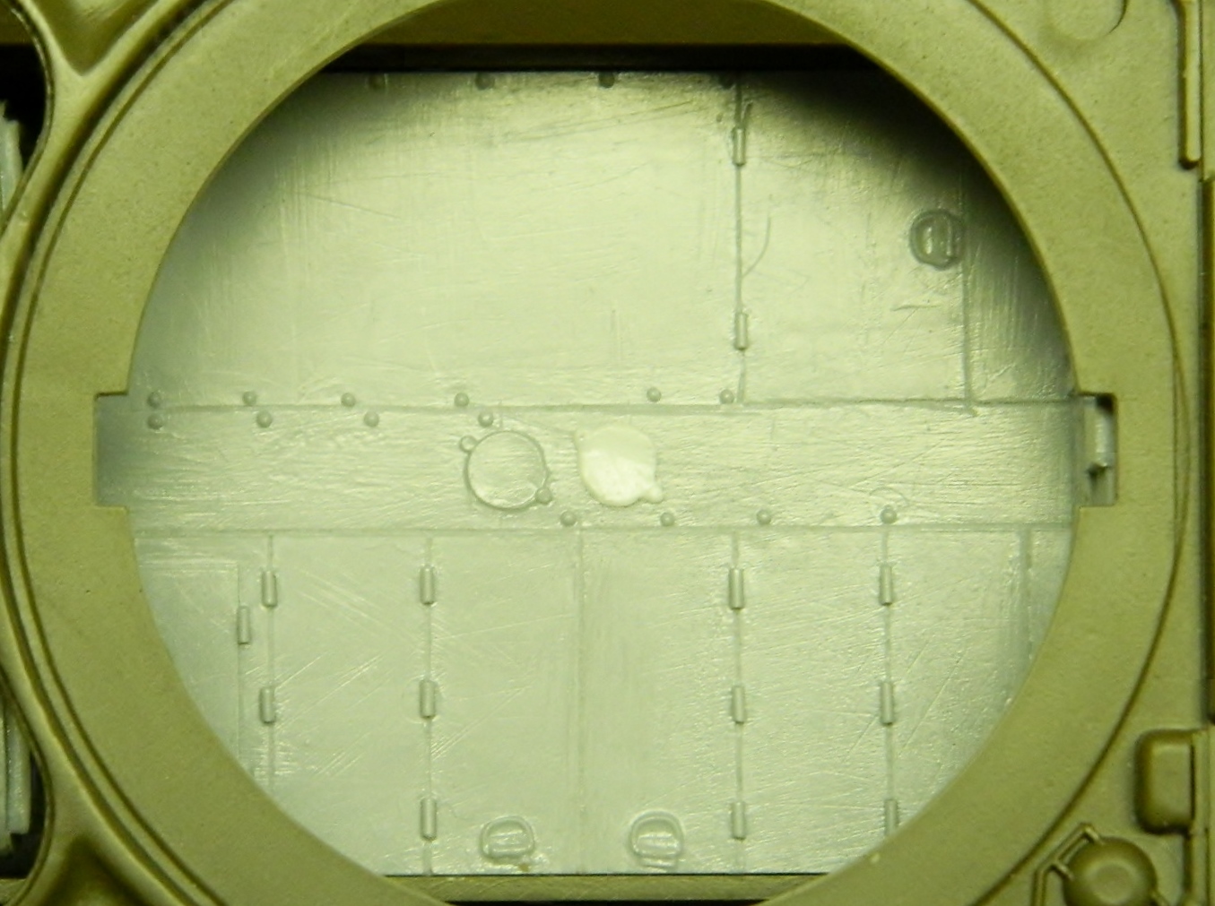
I punched out the appropriately sized discs to use for the drains (which are what those round bits on the bottom are). When I have to center a disc over markings, being able to see the markings makes things much easier (and accurate). To enable this, I punch out the first disc…the one that locates however many will follow it…out of clear styrene:
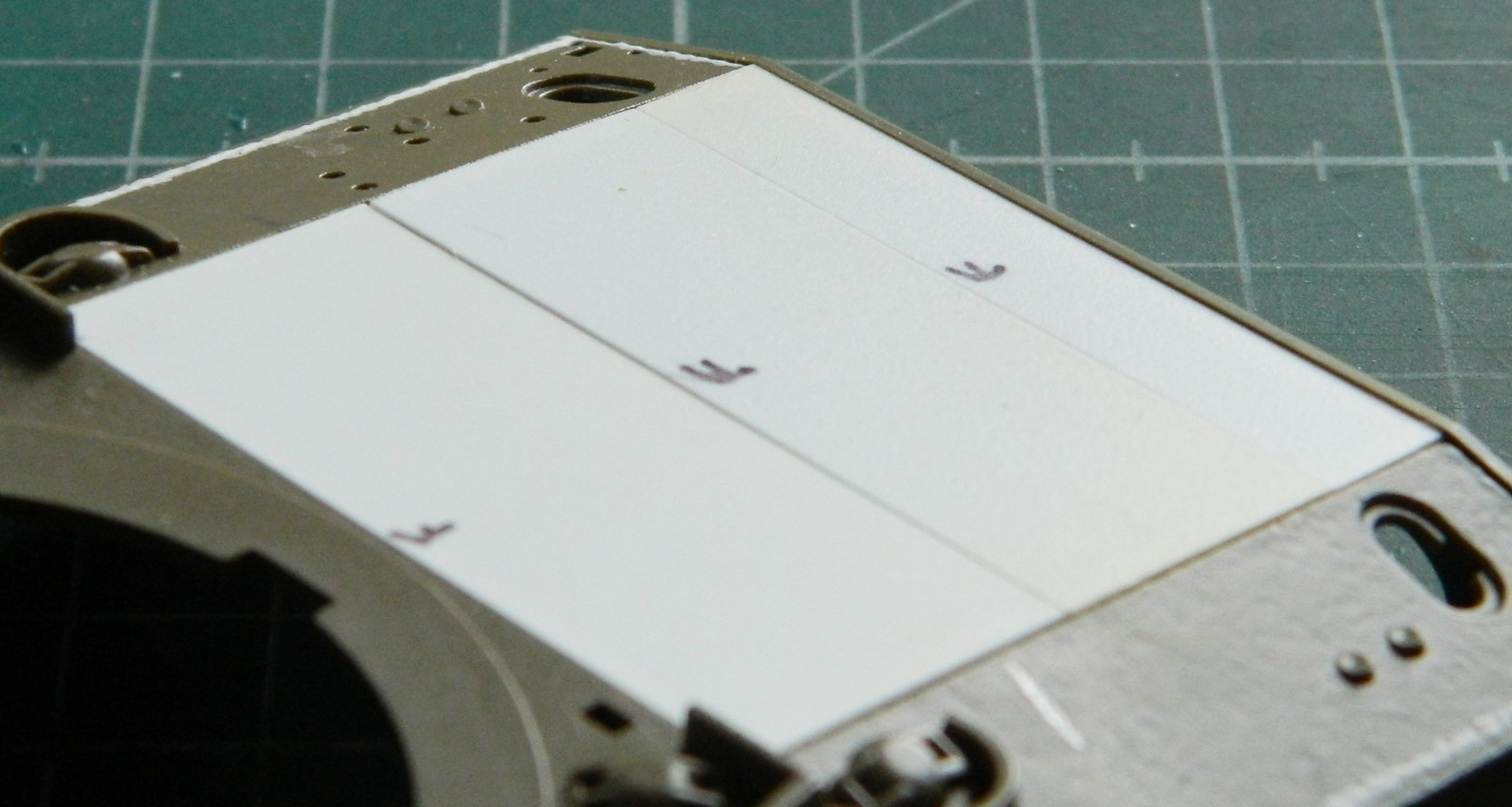
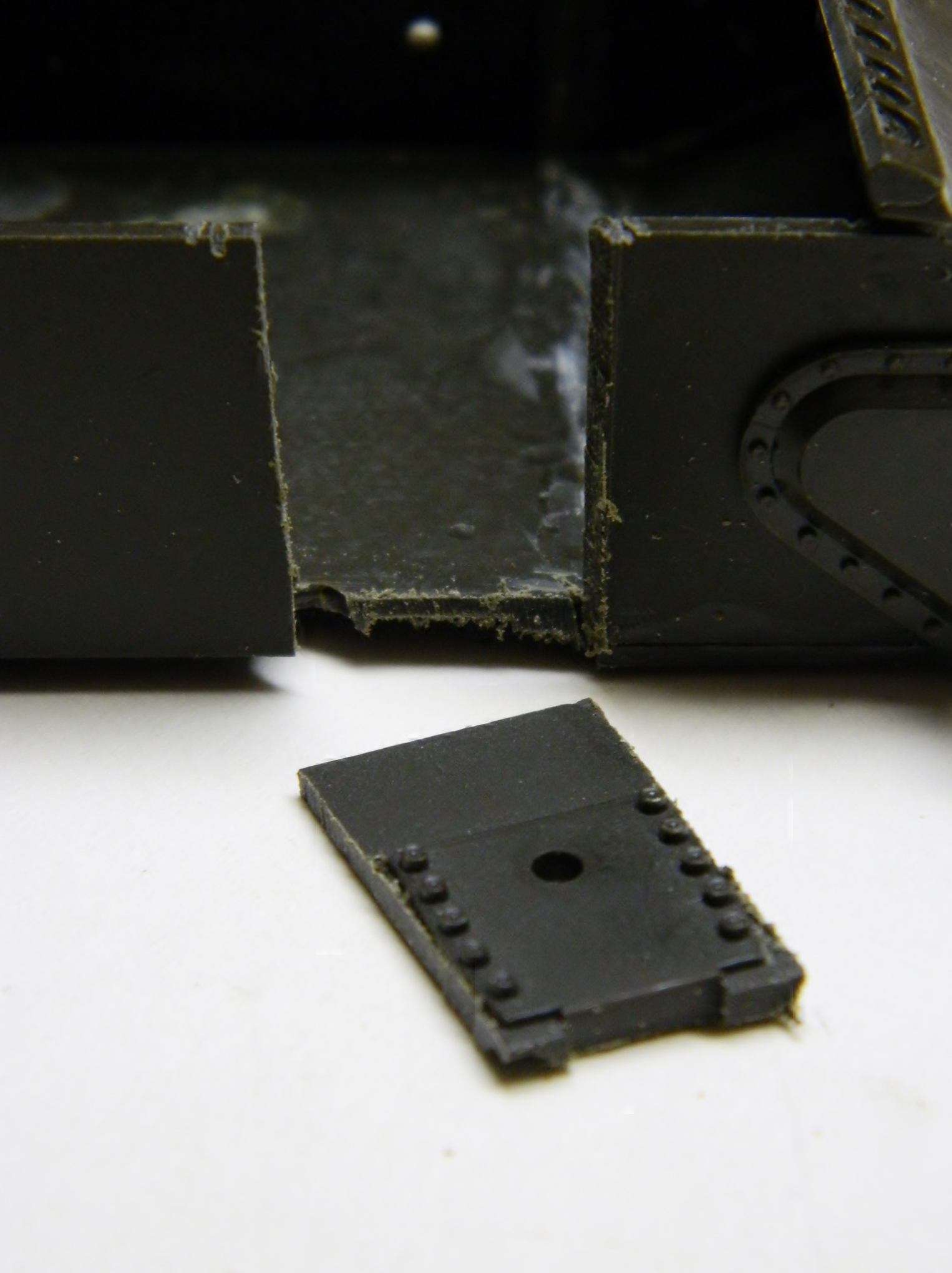
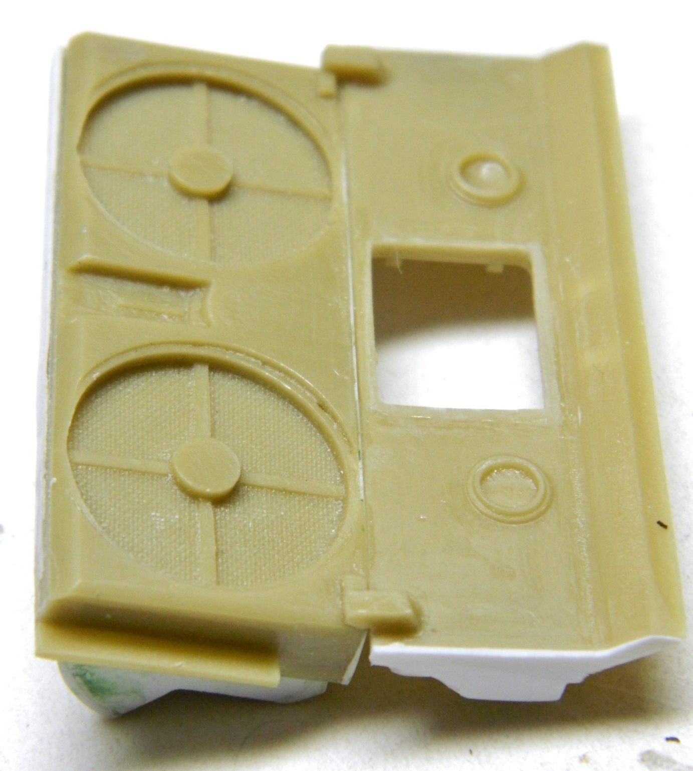
I wanted to add the lower engine access cover and escape hatch. With the locations marked, I drilled the corners of the intended openings to provide the rounded corners:

And right after I had all the holes drilled, I realized that the lower engine cover wasn’t recessed from underneath; it bolts into position and drops down when it’s unbolted. ::sigh:: I don’t know if those mistakenly drilled holes will be evident once the engine and upper hull are in place, but I do know that plugging those holes will be easier now than later. I took a piece of sprue from my extensive (and like the rest of us, growing) sprue stock, chucked it into a variable speed drill, and sanded and filed it to a taper so that I can glue it tightly into place(s):

And then it’s trim, file, sand, and putty where needed:


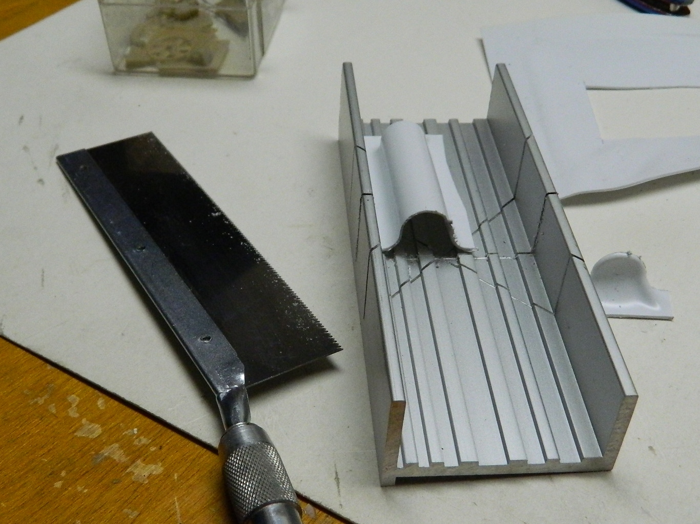
I also had to redo a couple of the saw holes for the escape hatch (switching to tea…which unfortunately has less caffeine than the kidney-flush coffee I make) (made):
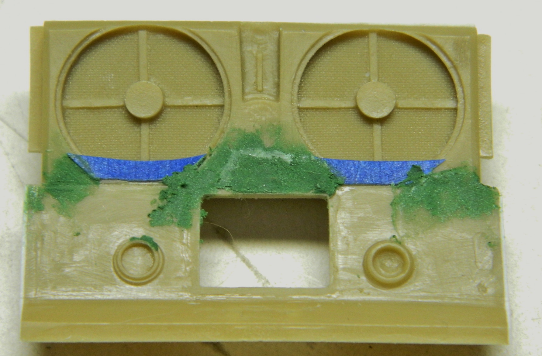
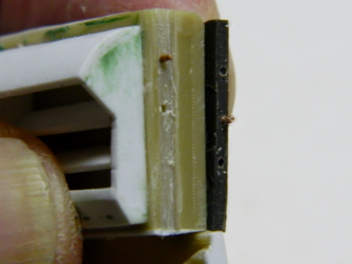
The thickness of the plastic in this area is MUCH thicker, scale-wise, than it ever was on the actual Sherman:

I think it was something like an inch and a half (about 38.1mm). The plastic is about 5″-6″ (126mm-152.4mm). The escape hatch sits above the opening, has a flange larger than the opening, and pulls upward to open. Rather than try to scrape the plastic to a more correct thickness, it was easier to open the hole and make a plug, pushing the plug to get the inch and a half (about 38.1mm) recess I was after (I think I used .030″ (.762mm) as the plug but I forgot to make a note):
I puttied over the plug on the inside so that the AM resin hatch would fit flush to the floor:
I copied some of the engine bay details from Mini-Art’s M3 Lee (Early). When I cast the floor, somehow I failed to notice that (what I think is the oil reservoir) has a substantial bubble:
I cut the hole to a relatively even hole, trimmed pouring block resin to a tapered fit, glopped a generous portion of superglue into the opened hole, and stuffed the tapered pouring block resin into the hole. I let it sit overnight so that the superglue was well cured (in the third photo it looks as if there’s a gap around the plug but there isn’t…that’s superglue). Once painted, shaded, and with a radial engine stuffed into the same area, I doubt anyone will ever see it, much less be able to critique my patching job:

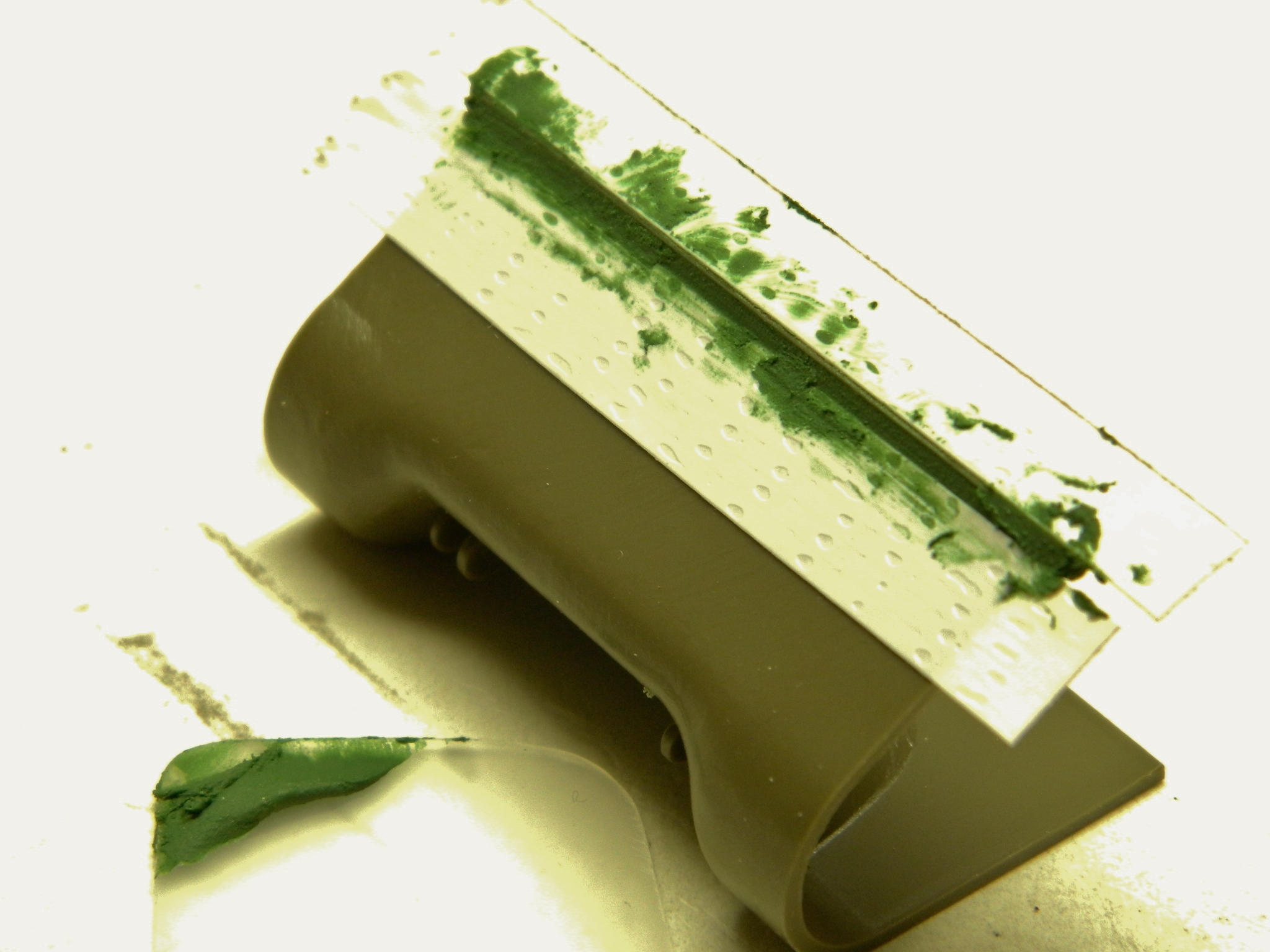
I used Squadron Green putty to make my first pass and blend the added plastic to the diff cover:
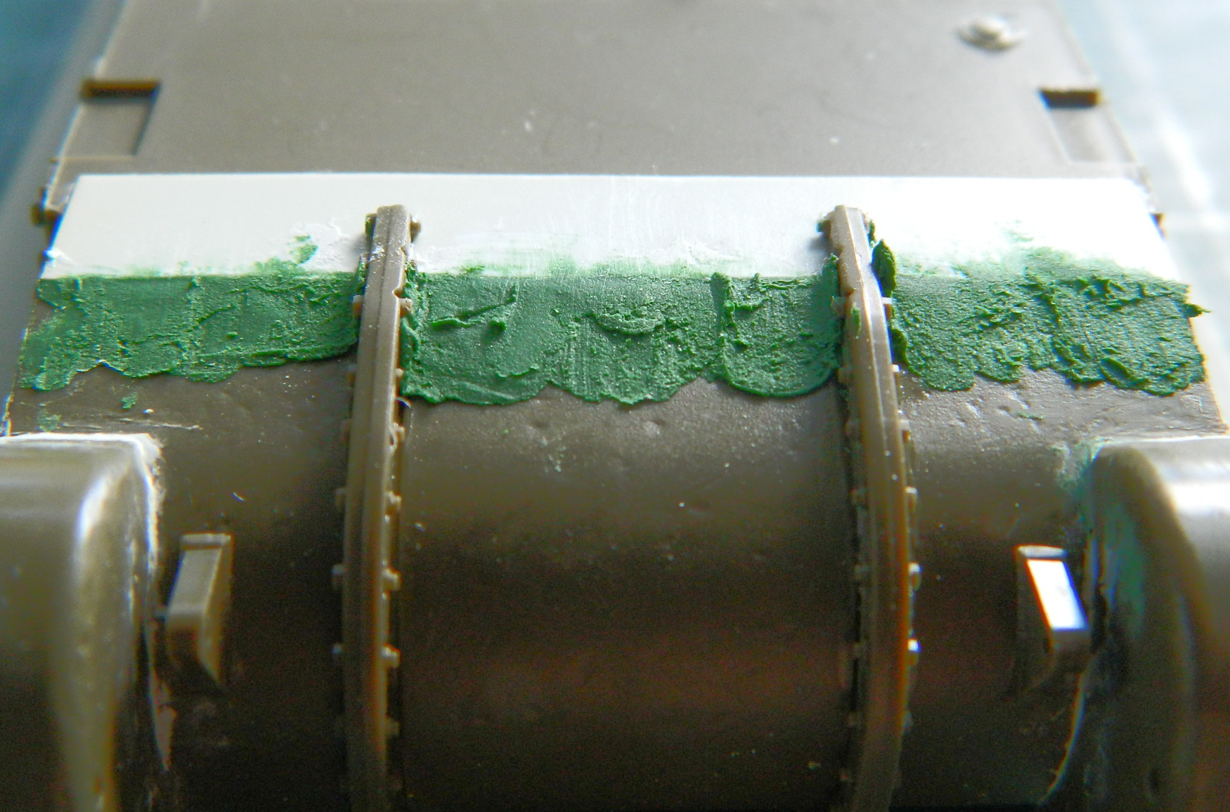
It was okay, as far as it went…which wasn’t quite far enough, so I used 3M’s Acrylic Putty to finish blending. Later I will add bolts because the differential cover, whether three piece as this one represents, or a solid casting, all bolted to the upper and lower hull (I should also probably get my mitts onto some Mr. Surfacer as well so I can replicate the as-cast texture):
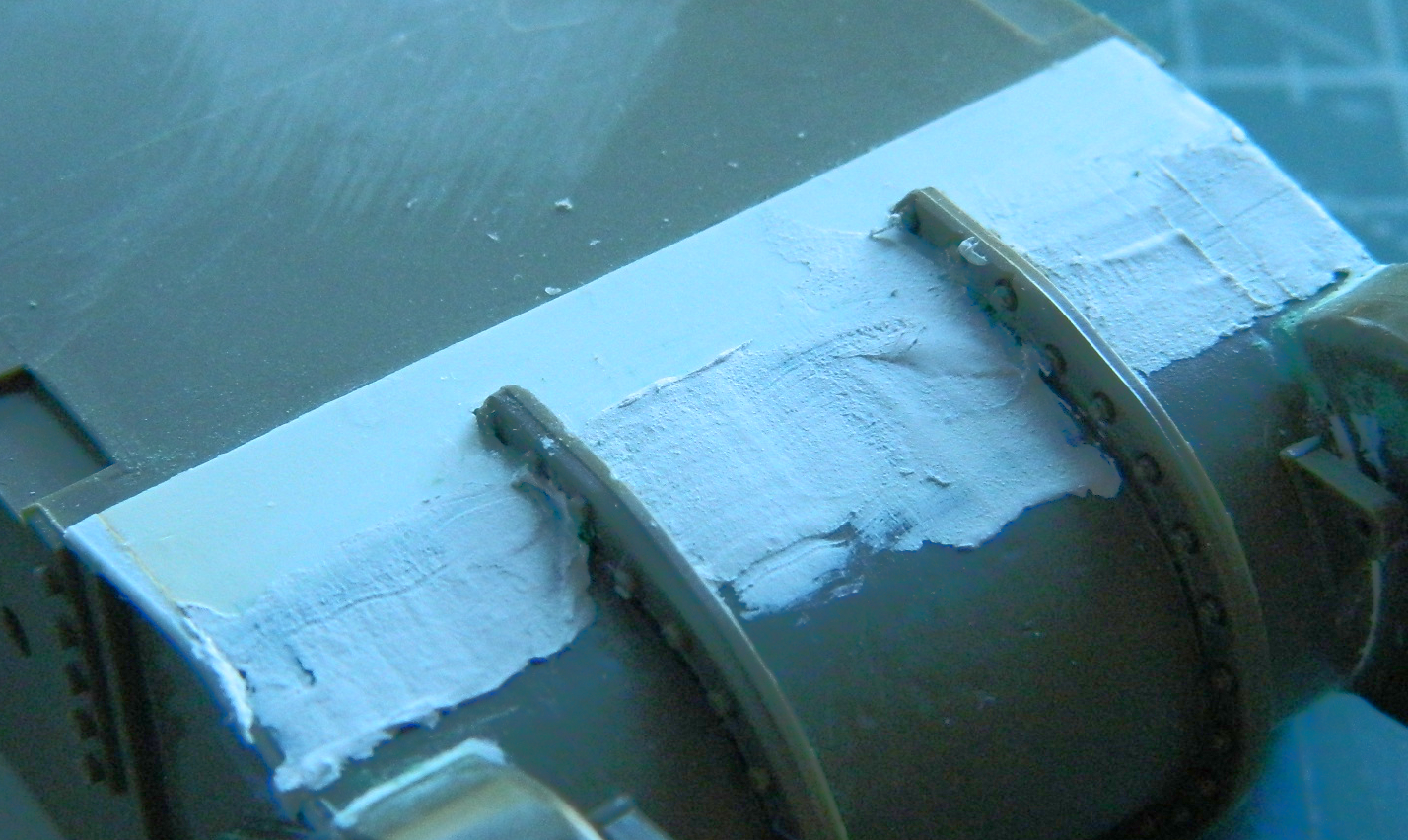
I used .020″ (.508mm) styrene for the lower engine access plate (which will also get bolts added):
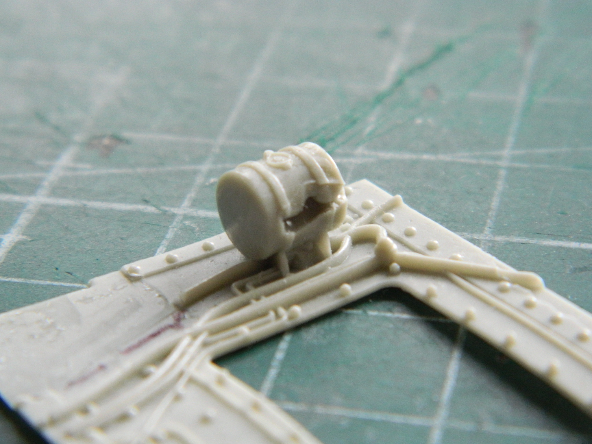
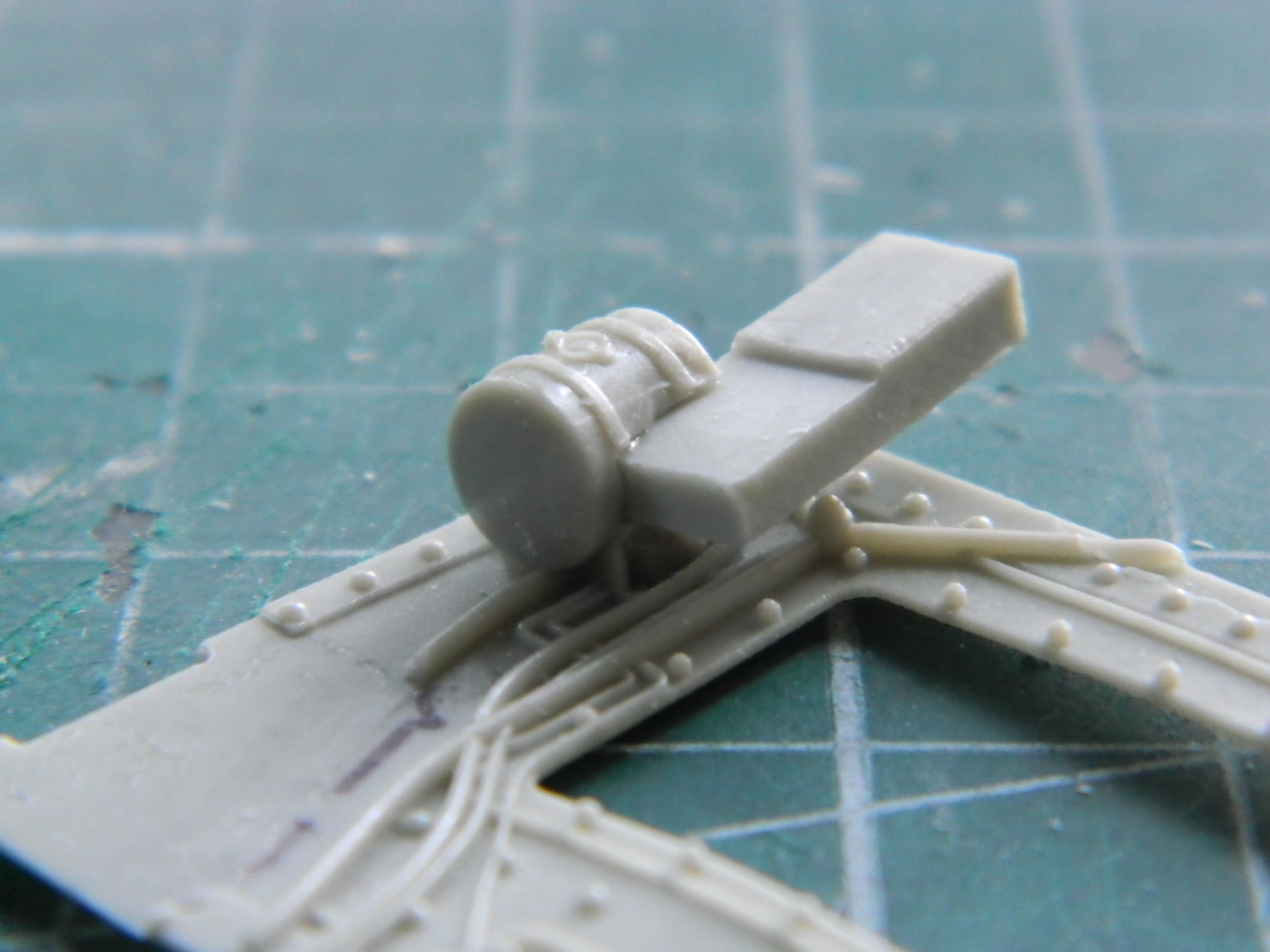
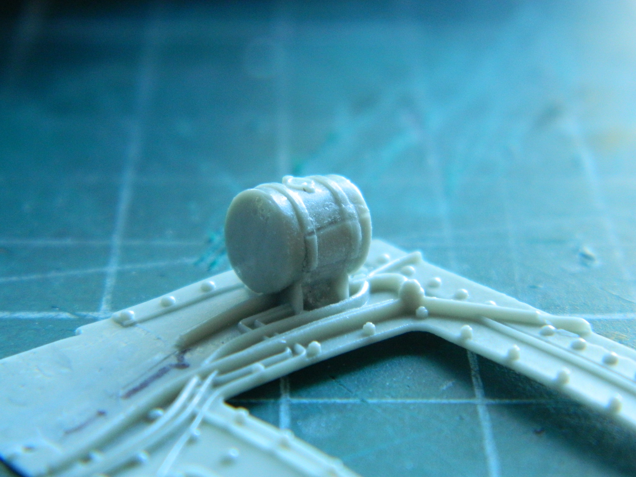
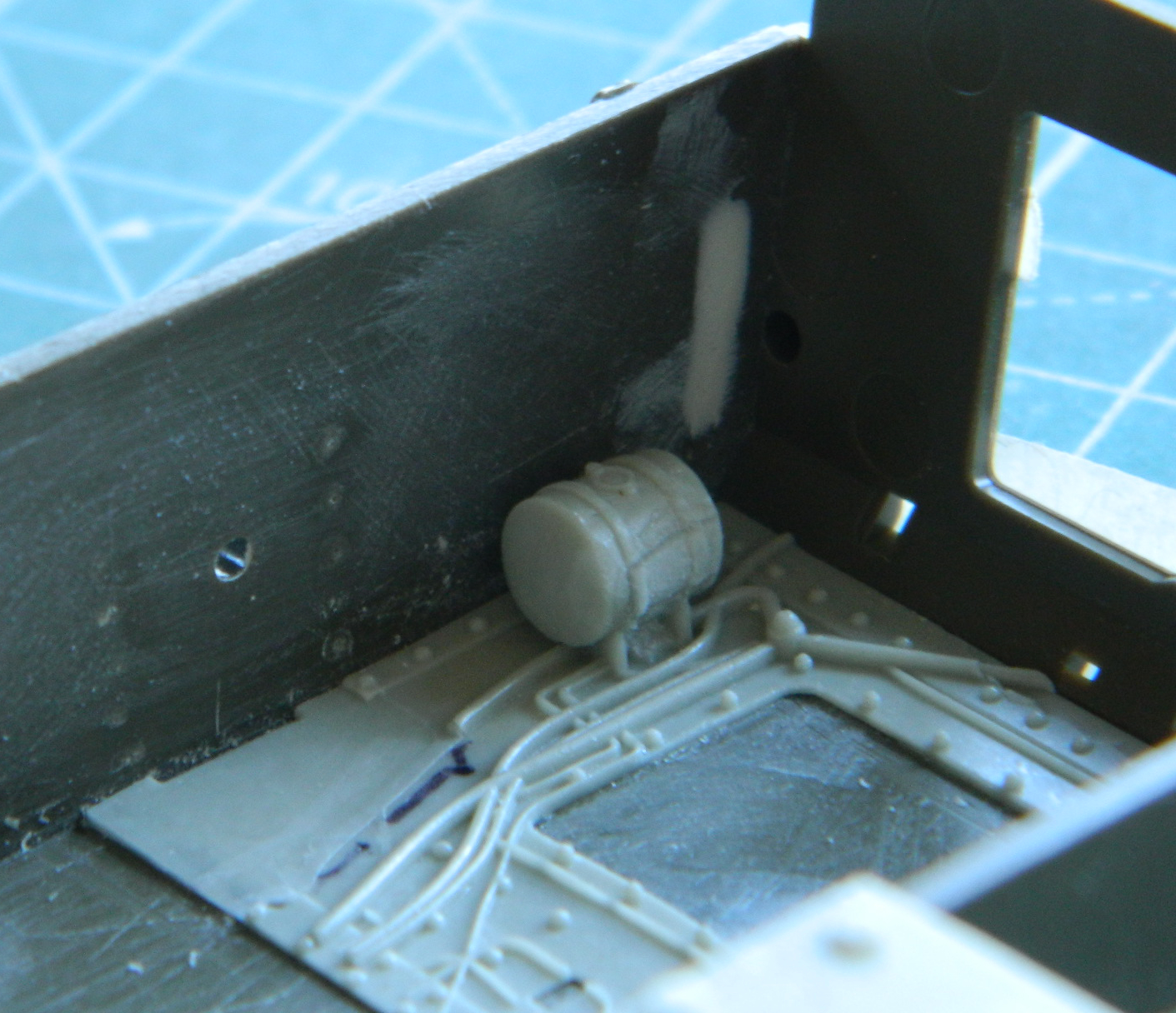
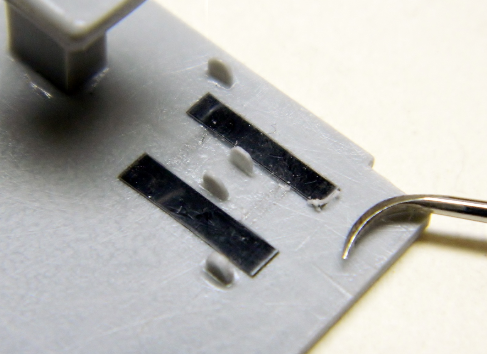
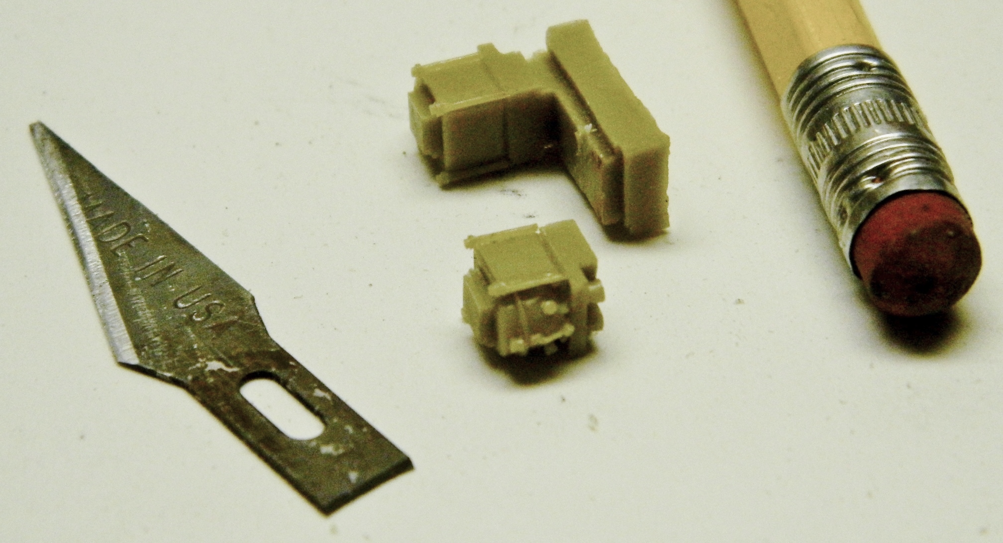
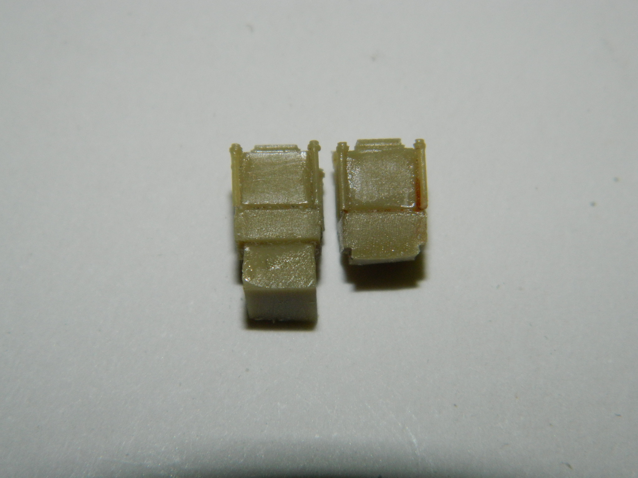
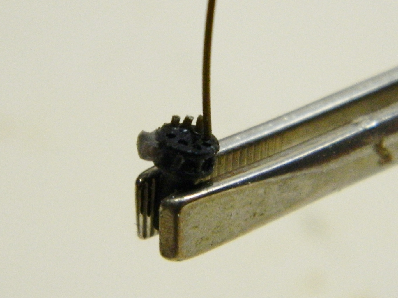
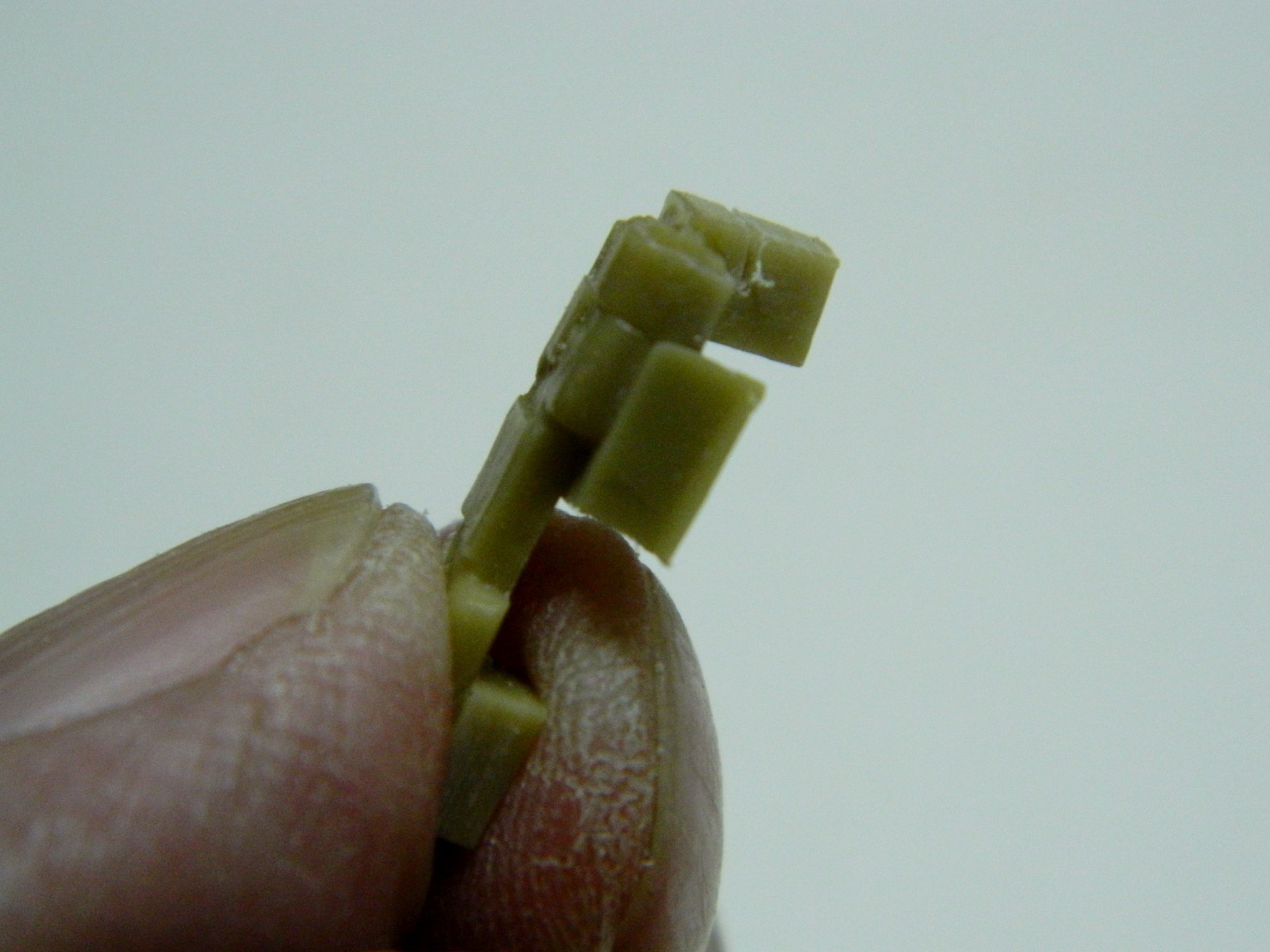
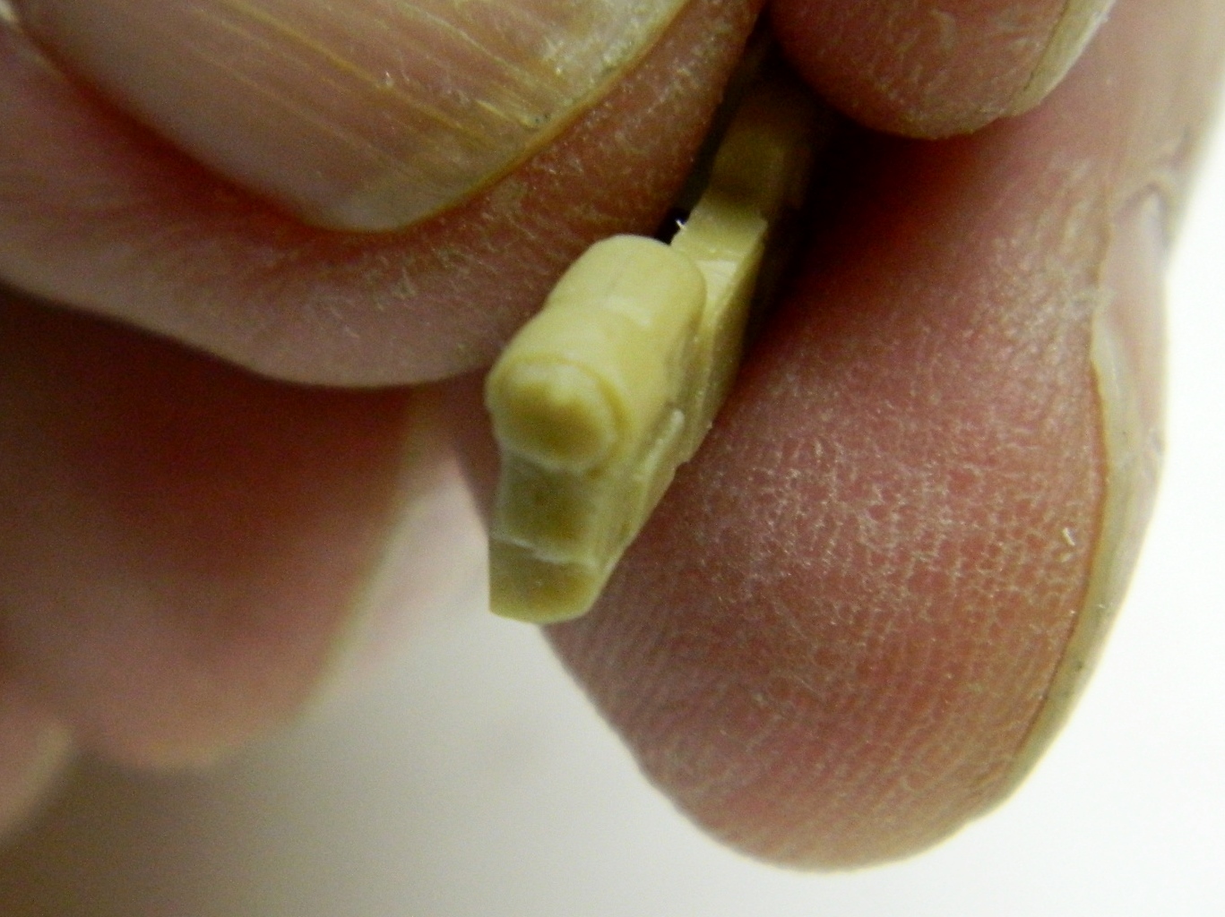
Back into the crew compartment, I started working on the canisters of the fire-suppression system. This starts with cutting away the pouring block and putting back the detail lost. It also entails reattaching the valve/gauge assembly that got knocked off (using my traditional pin and glue method):
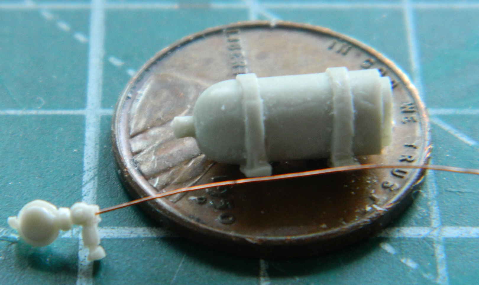
I get to do this again because there were two canisters (and you can see where the gauge has already been knocked off the valve…or it simply didn’t pour):
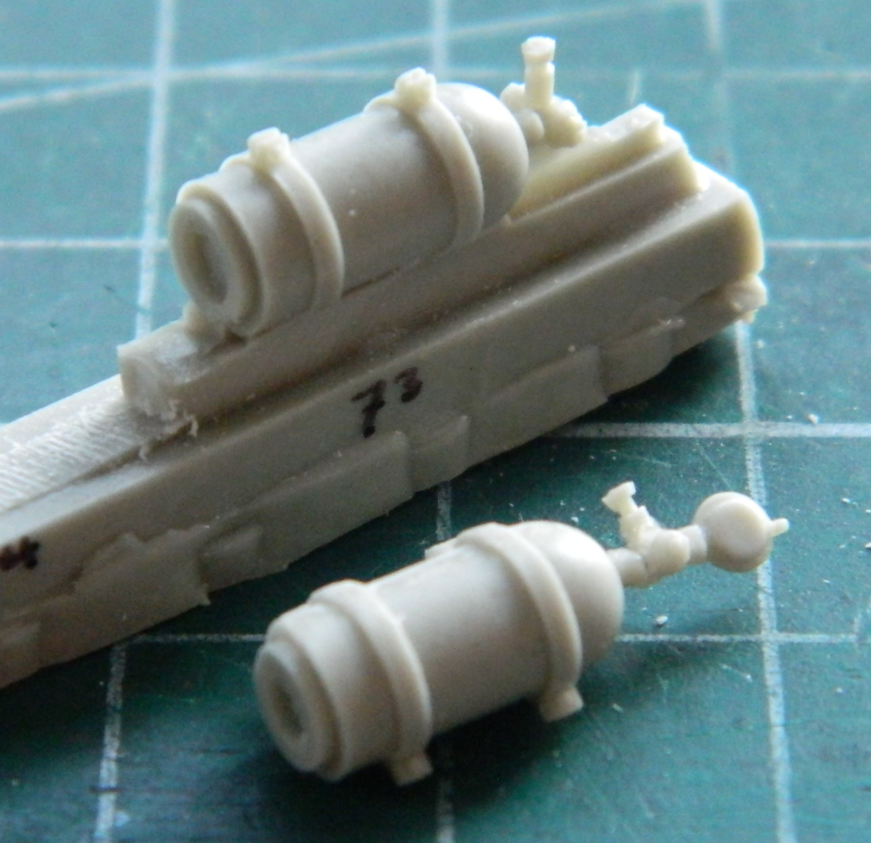
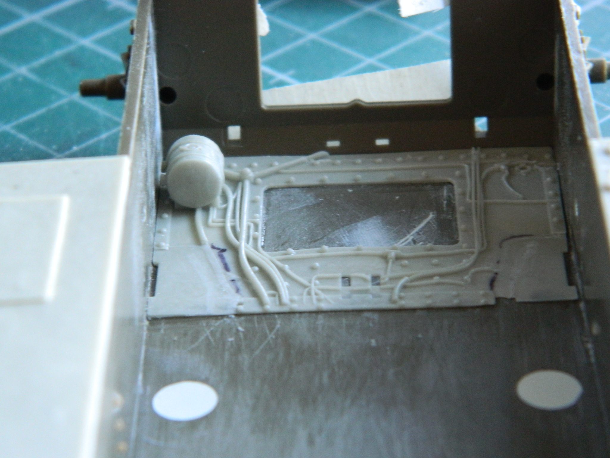
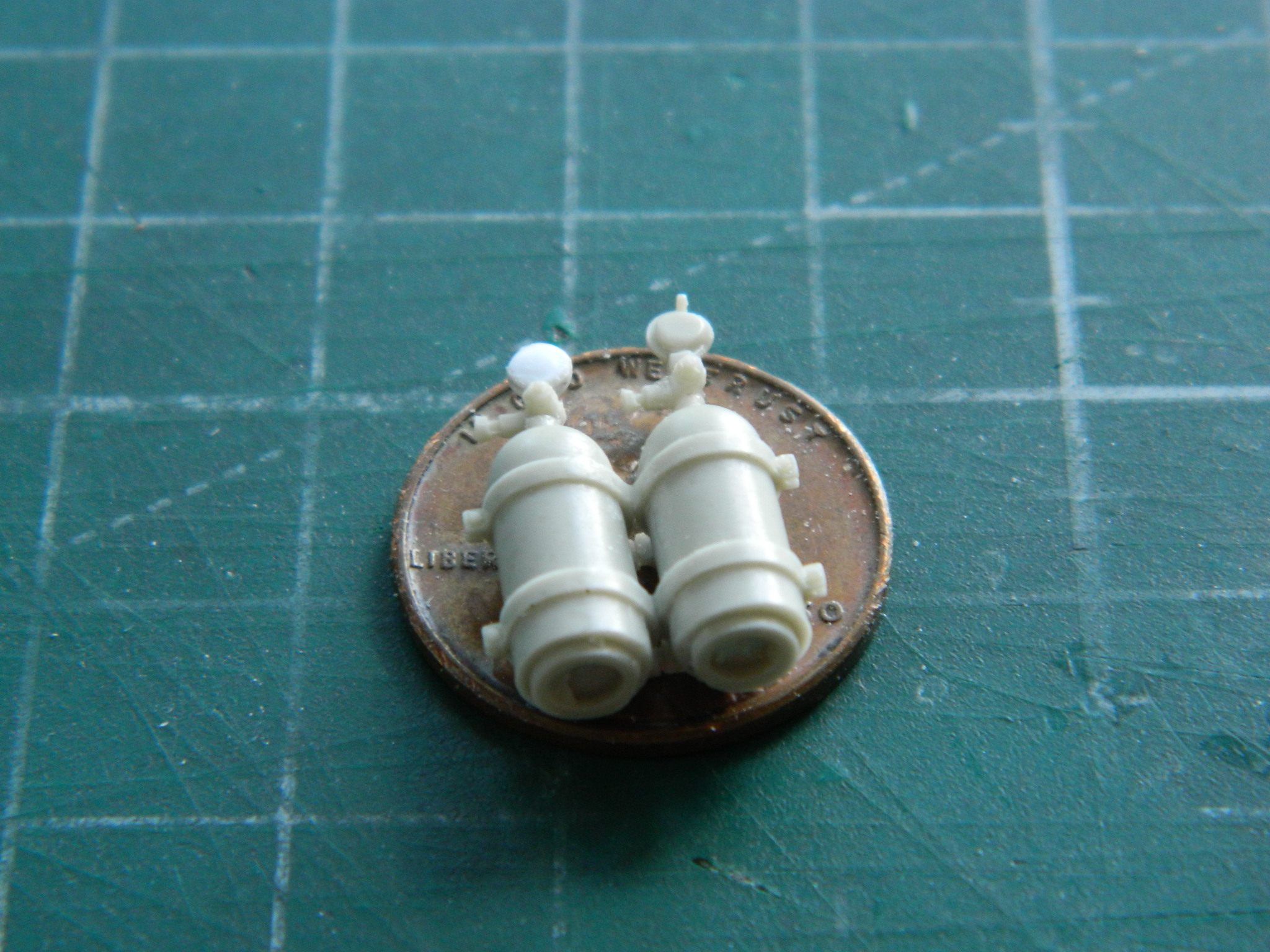
I used the punch/die set to knock out three discs to make the gauge and before I add the conjoined canisters into the interior I will add the Mystery Bit (seen on top of the other gauge):
With most of the details added to the belly of the tank, I used Vallejo’s Acrylic Putty to fill in the alignment marks and mistakes. Since I’ve brought up the subject of mistakes, gimlet-eyed readers have no doubt noticed that I have extended the resin sponson bottoms all the way to the back of the sponsons. Yep…correct for an M4A3…incorrect for an M4. (This also explains why the AM set has abbreviated sides…Tamiya actually provided the parts that would otherwise go there, so both the sponsons and the upper sides of the engine bay will get trimmed. Later):

Since it isn’t the 60s anymore (and I am not a kid) (substantially), I am not a fan of “working features.” Having said that, I again remind y’all that I am a creature of mood and whimsy. Not understanding why myself, I have decided that the engine covers must open and close. (Well, doesn’t THAT simplify things! Having had Covid last month, I blame Covid-brain.) I started with the rear engine doors. I held the doors in place and drilled through the hinge parts in one pass, thereby making inserting the wire I’m going to use as hinge pins even possible, much less easier:
That worked well, so I tried it on the top engine covers. That didn’t work worth a rodent’s rectum. That so didn’t work that I bitched up the kit’s front engine cover (very thin drill, too far to go to reach the areas that had to be drilled, which caused the bit to bend and the hole to be drilled as a curve, and that utterly screws up a hinge). Okay. Since it has become evident that I cannot drill out the hinges with them in situ, the end result is that to have the top engine cover open, I have to scratch-build it.
Lovely idea! Let’s DO that!
::insert eye roll here::
The upper engine covers are three parts, of which two bolt into place. The front engine cover (which is the one I bitched up) has the air inlet for the engine’s cooling fan (obviously, Shermans with the Continental radial aircraft engine are air-cooled), as well as a couple of armored fuel cap covers.
Step one is to cut three pieces of .015″ (.381mm) styrene to replace the kit’s covers. I used the thickness I chose for scale thickness. Once I had all three parts cut (which for simple rectangles took me far too long) and fitted, I noticed that allowance had been made by the kit engineers for the out of scale engine covers to sit flush with the surrounding surfaces. That meant that the scale thickness covers were recessed and should not be:
My first attempt used .015″ (.381mm) shims to raise the covers:
That didn’t exactly do it, as the center cover in the photo below shows:

Since both for forward and rear covers are typically bolted down, I shimmed the covers and not their seat, which is why in the above photo they sit even with the surrounding hull. I added .020″ (.508mm) strips to the shims already glued down and that brought the middle cover up to where I want it:
The rear and front cover will have bolt heads added later. For now I have to get the missing details added to the front cover. That started by sawing off the bullet-splash lip:
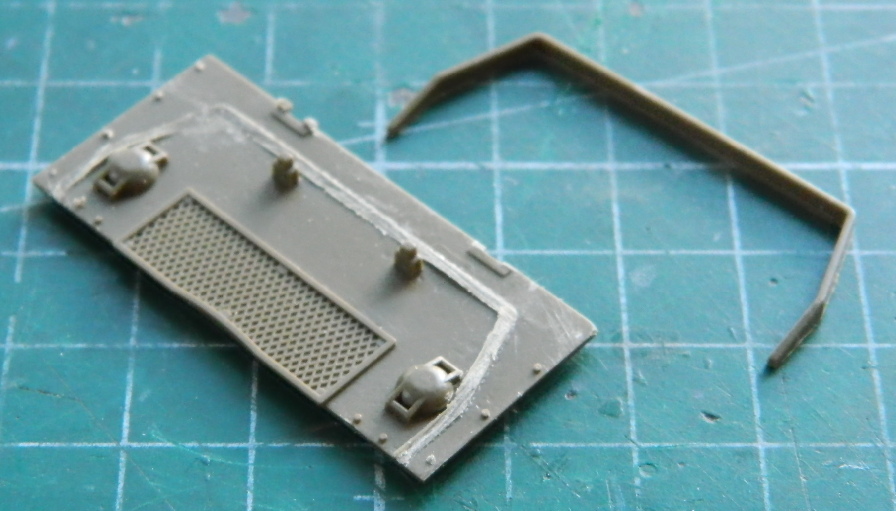
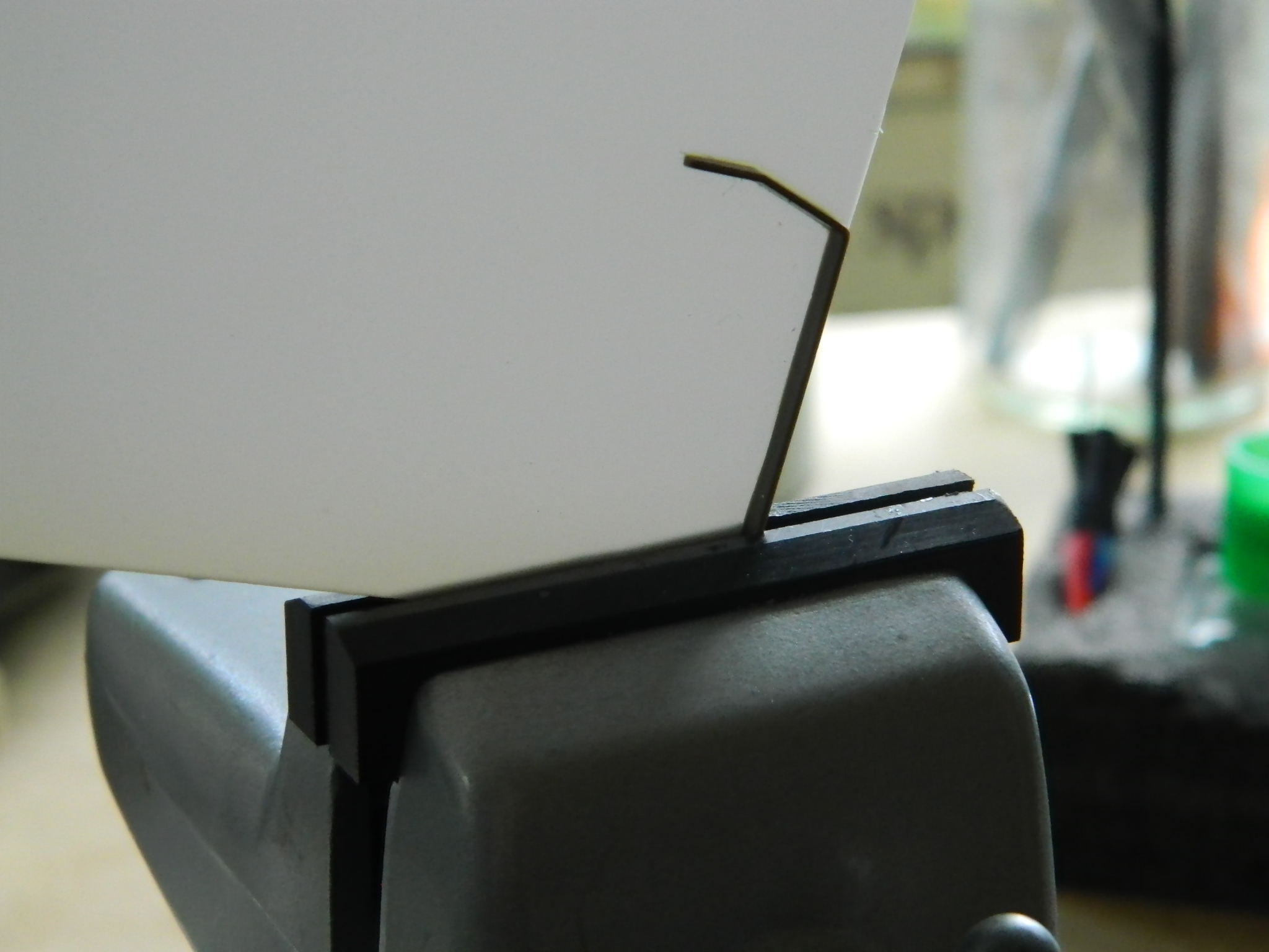
You can see that it wasn’t my cleanest excision. I cleaned up and leveled the U-shaped part (on the right in the above photo) and then glued it down to a flat section of .015″ (.380mm) styrene to replace the kerf. Once glued onto it, I could see an area where the plastic of the excised part didn’t meet with the plastic of the kerf replacement. I added a couple of pieces of .010″ (.254mm) and .005″ (.127mm) to fill in the gap:

I applied Tamiya Extra Thin cement liberally and once the plastic started to melt, I clamped it all into a vise to cause the squidge to flow and fill gaps and to make the gooey plastic a bit more level:
And what with all the cutting, fitting, fixing, and of course Colorful Invective (often applied while crawling around looking for the sodding small part that just tried to “tick” its way to oblivion), I never did do any work fitting that engine…
M4A3 (Tamiya) Build #26 – Fun with Tracks (Part 2), Painting Exterior Details
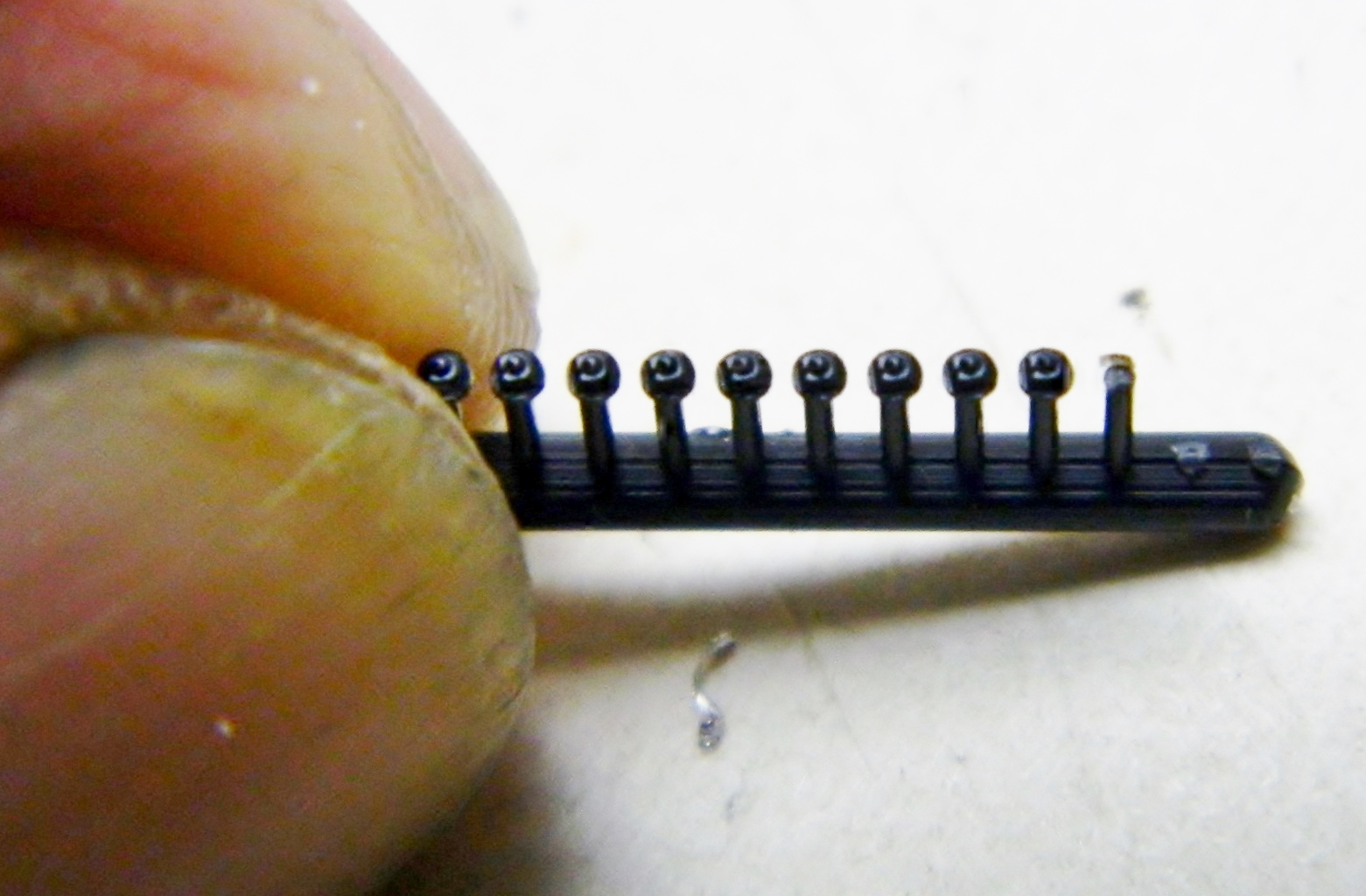
There was a hold placed on this build, which is obviously now over. The problem was with the tracks. Having never used individual track shoes before, I thought I was being “clever” by gluing the sections that would be flat in the thought that doing so would make the tracks easier to install. Such was not the case. When it came time to install the tracks on the model, the pins of the track shoes kept snapping. I tried drilling out the connectors and the shoes, inserting styrene rod to replace the snapped pins, and as far as that went it worked. Unfortunately, as I fixed one shoe, the one next to it would snap…and the one next to that…and having done five or six that way, I sorta figured that I would end up drilling and pinning ALL the shoes on BOTH tracks:

Time to cut my loss, order a set of new tracks, and start the whole tedious process again. [Insert industrial-grade whining here] And that’s what I did.
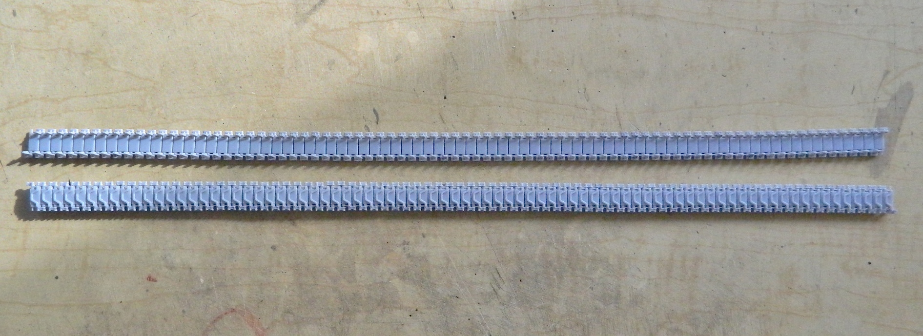
It seems as if even a little bit of experience is a good thing. I figured out a new way to clean up all the connectors and shoes. The first run-through with individual track links took me about 40 hours to clean up 158 track shoes and 316 connectors. The second time it took me about 15 hours to do the same thing (my shoulder is still sore from all the back-patting I did):


During that 15 hours (spread over three days), I spent a lot of time trying to figure out why those pins kept snapping. I mean, I only dry fit each track on both sides a half-dozen times… So the first determination was that I would only fit this set of tracks once per side and then glue them in place. And something about gluing kept nagging me. The pins on the track shoes ARE SMALL. They are also plastic. Hmmm…
With sections glued, the torque stress of putting them on and taking them off showed the weakest part of the tracks; the little plastic pins. I’m figuring that by not gluing them prior to fitting them onto the model, those stresses won’t be concentrated on those little bits of plastic. Yes, with the connectors only pressed on the tracks will droop and twist. But each time they droop and twist that force will not go to twisting the pins. Okay, now I have two runs of tracks put together but not glued at all:
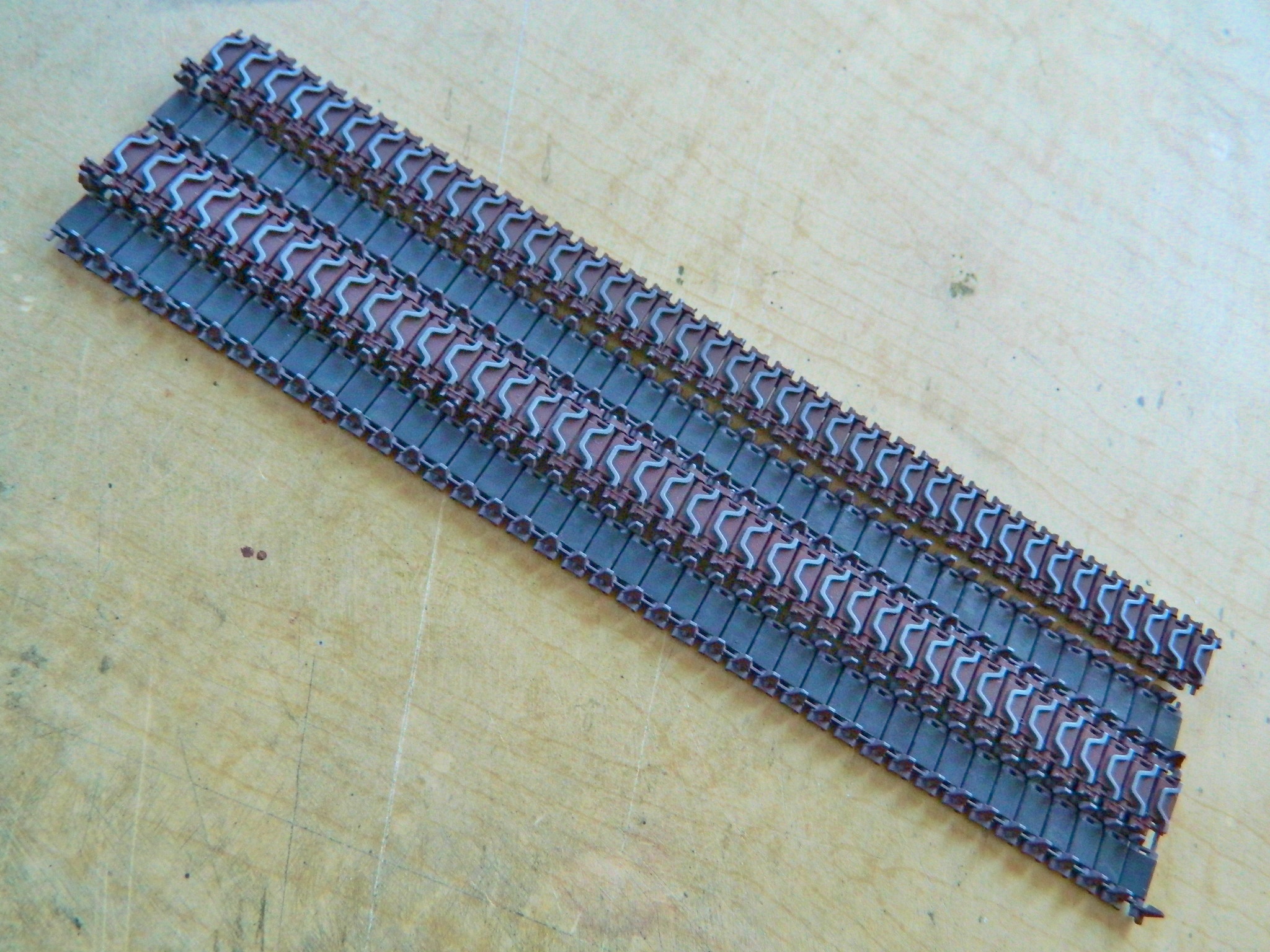
Next, they get painted the same way the last set did; steel, rusty brown, and rubber black. I start with steel and buffed the track faces (and do please note that this time I got all the chevrons aligned in the same direction):

I was not looking forward to the masking process. So much so that instead of masking the tracks and airbrushing the rubber paint after doing the rusty brown, I brushed the rubber on before the rusty brown, then shot the rusty brown on the faces and connectors, using acrylic thinner to clean the chevrons:

I set them aside to let the paint set up a bit more and turned my attention to other items that need paint. First I did the .50 caliber (1.47mm) and added the ammo box and belt:

I painted the coaxial .30 caliber (7.62mm) and then added the mantlet:

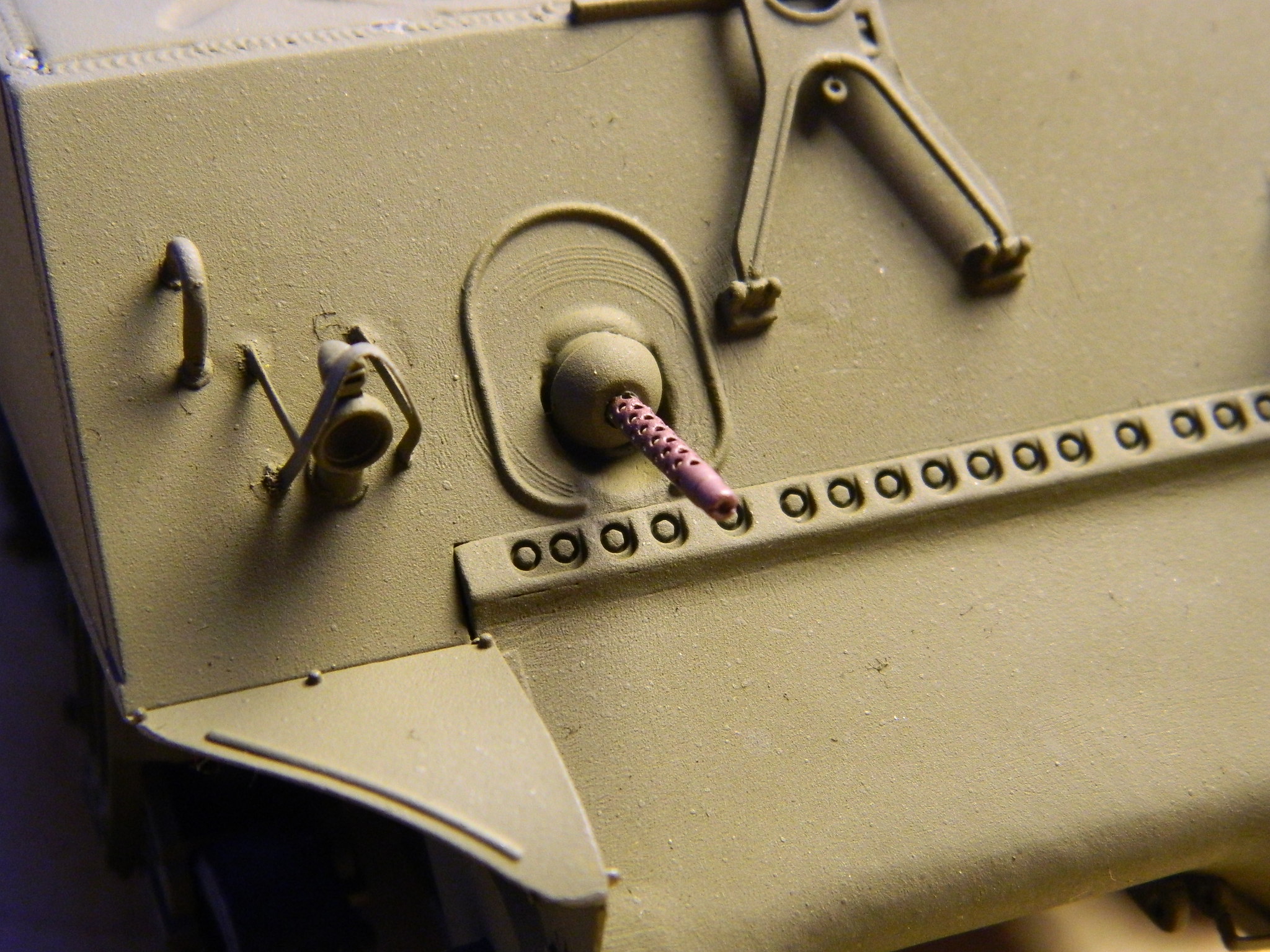
And then I painted the bow-mounted. 30 caliber (7.62mm):
I won’t be surprised if touching up needs to be done after final assembly, but I’ll bridge that cross when I get there. First I have to get the tracks mounted…
M4A3 (Tamiya) Build #8
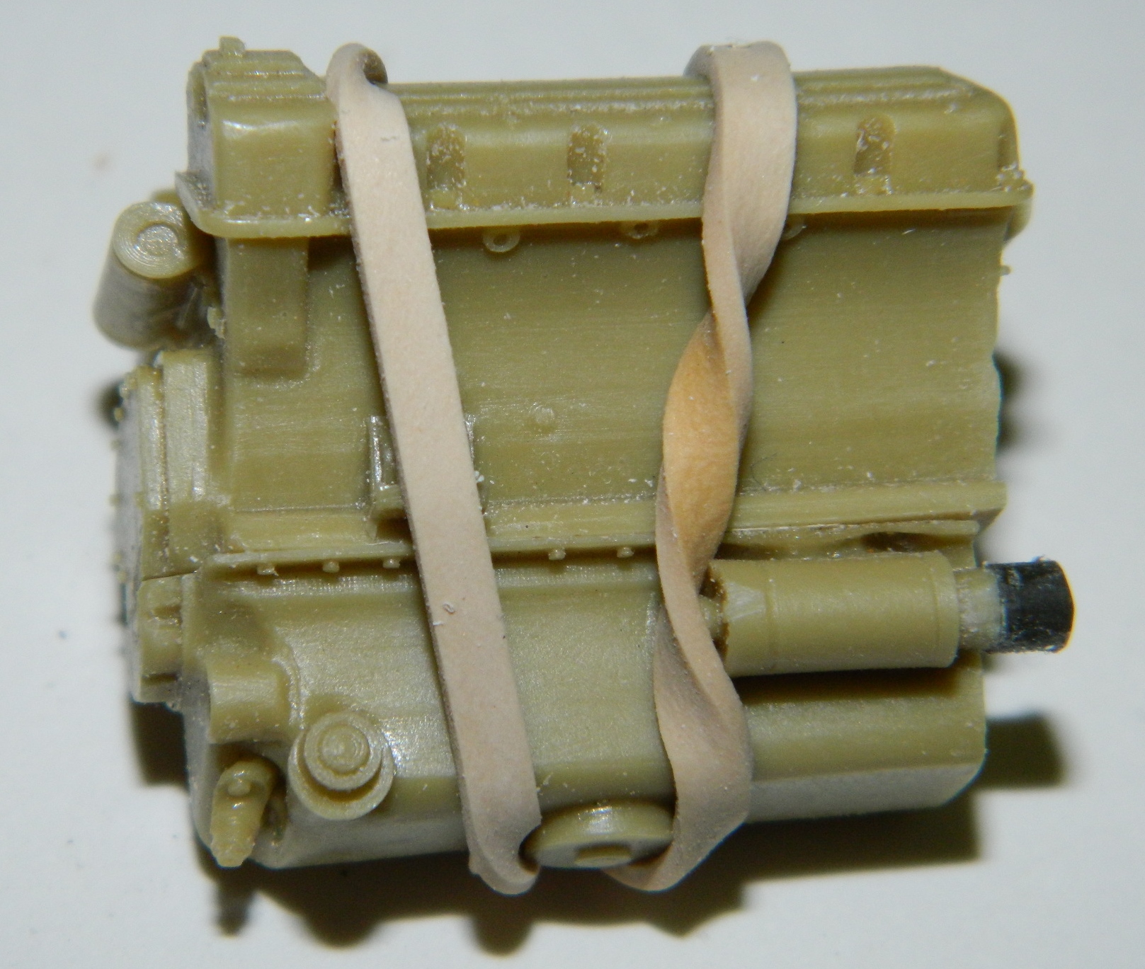
Satisfied with the results of the salt-chipping experiment (and grateful for the break it provided), it was time to go back to work on the coolant manifolds. The putty was well set and I shaped them:
With the tapers done, I had room to add the rest of the coolant manifolds:
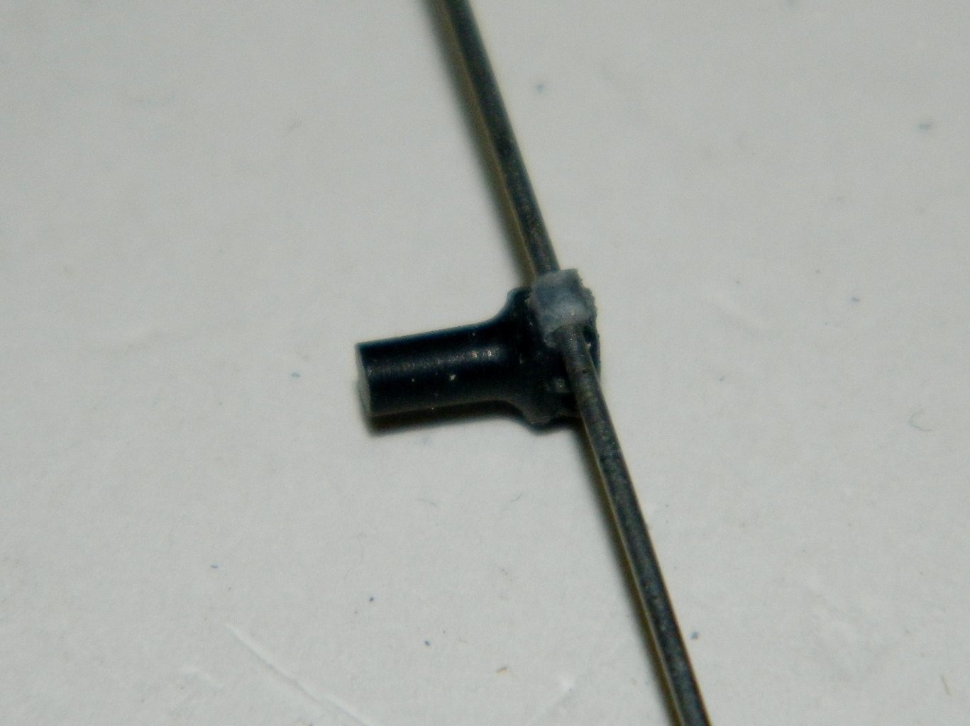
Because of the small size of the parts and the necessary bends them, using wire or plastic didn’t work. The wire is too stiff to bend and the plastic tends to crack and break when bent, so I went to solder again and I drilled out the end of the solder to fit over the manifold the way the rubber hose does on the actual tank (but more to avoid butt joints, really):
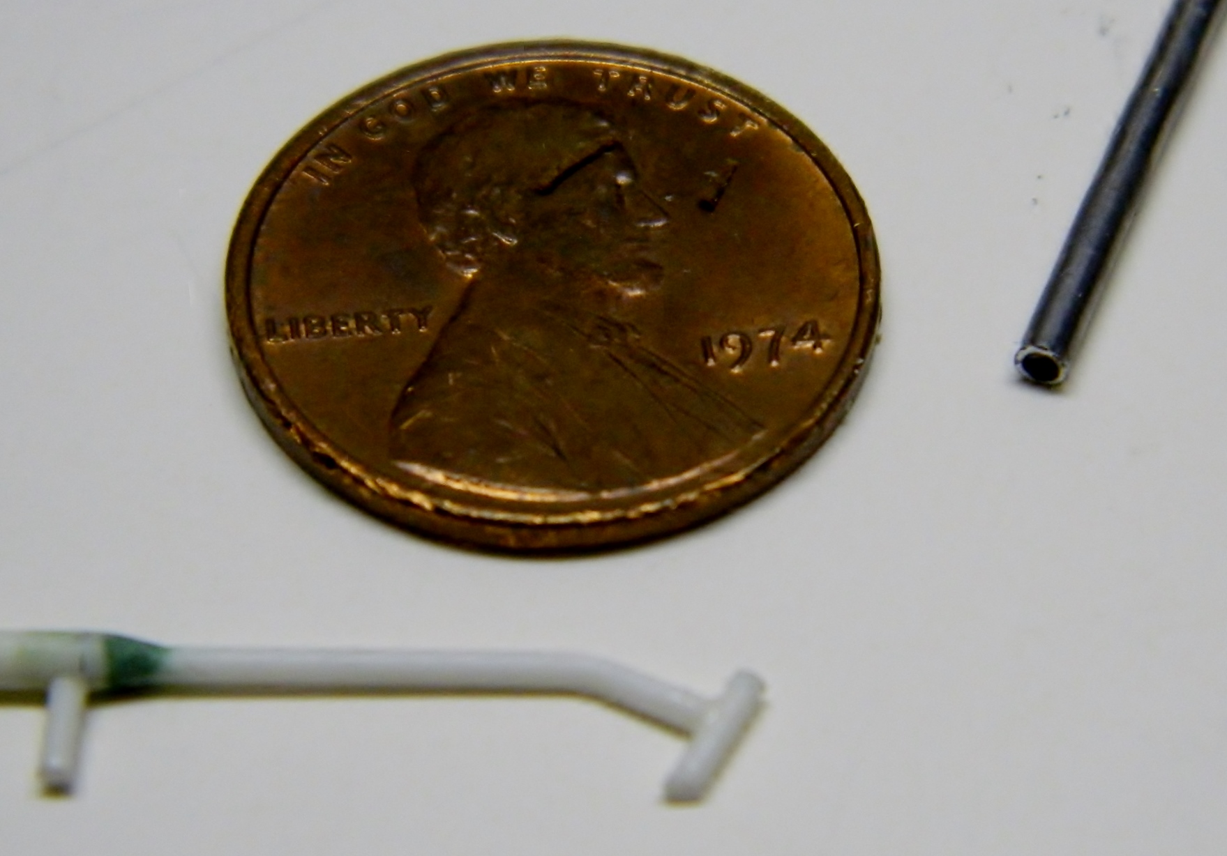

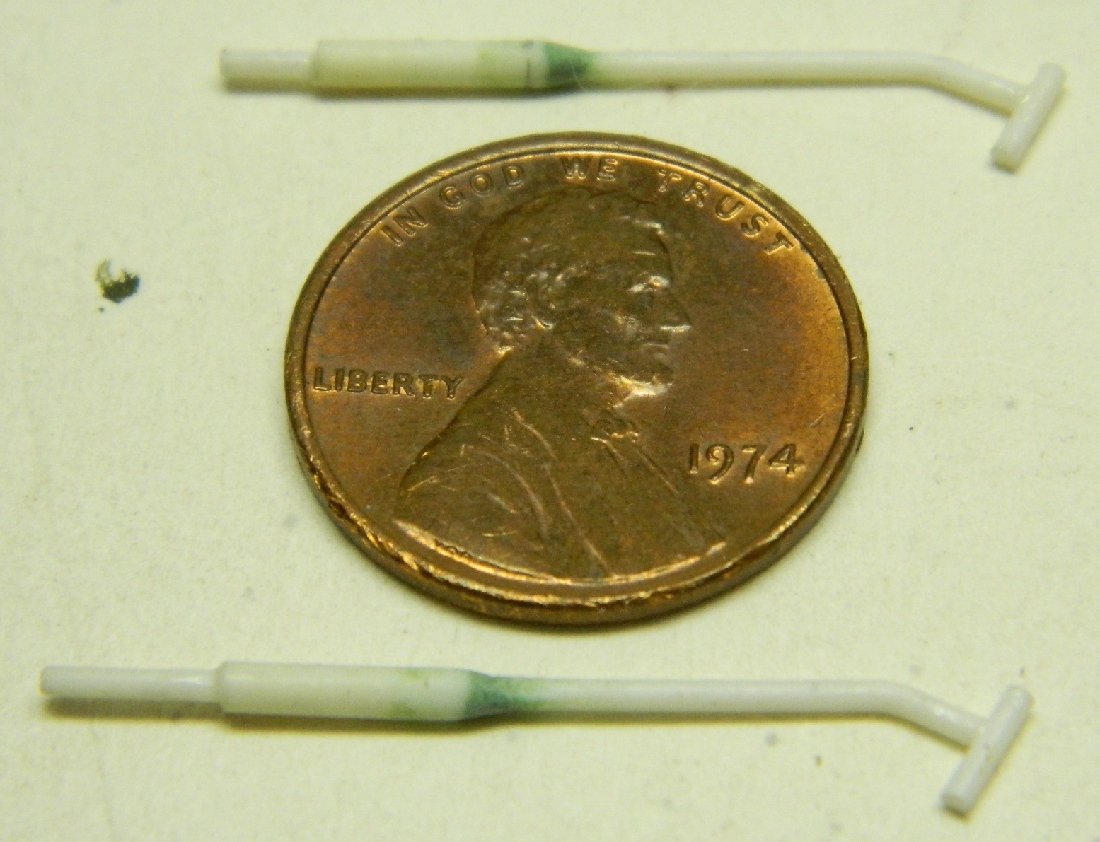
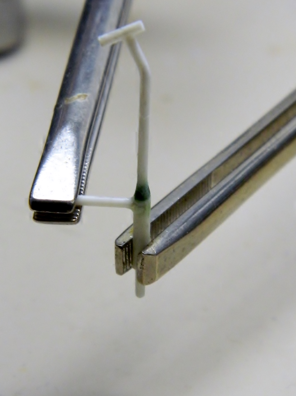
Also quite visible is the dipstick so I used some scrap sprue, heated and stretched it, and glued together the t-shaped dipstick:

And then I realized that having the solder “hose” attached now was just too awkward; they’d have to be added later, so I had to peel the solder off the plastic:

Time to set the engine aside for a while and start putting the “fighting compartment,” where the crew sits and works, together. Step one in that process is cutting the parts away from the pouring blocks, cleaning them up, and assembling them. I started with the driver and co-driver’s seats:

Once they were cleaned up they were put assembled and glued to the front floor-insert (the rest of the parts shown are just dry-fitted):

Test-fitting, or “dry-fitting,” as it’s called (“dry” because no glue is involved, this is done to see how or IF the parts all fit), showed another inaccuracy. On the gray, inner, part seen through the large hole (that’s where the turret will sit) there is a round part in the center and off to the left. That’s supposed to be centered under the turret so I’m going to have to move that:

To do that, I took some HEAVY aluminum foil and pressed it down around the detail I want to move:

Then I filled it with homemade structural putty that I concocted by dissolving styrene scraps in liquid model cement. The cement works by dissolving the pieces of styrene and once dissolved, the scraps made a gooey plastic that is stronger than commercial filler putty for when strength matters (the goo isn’t as dense as the styrene kit parts but is substantially denser than putty). I used that structural putty to fill the impression in the aluminum (if you’re unwilling to wait overnight for the glue in this solution to evaporate out, you can take THIN shavings of styrene, overfill the depression, and hold the plastic-filled aluminum over a candle, moving it closer until the plastic starts to melt; you’ll have to fiddle with the distance to the flame so the plastic doesn’t get hot enough to char or ignite) (don’t ask how I know this):

The next day after it had cured completely, I popped the new detail out of the foil, and then trimmed, thinned, and glued into a more correct location:


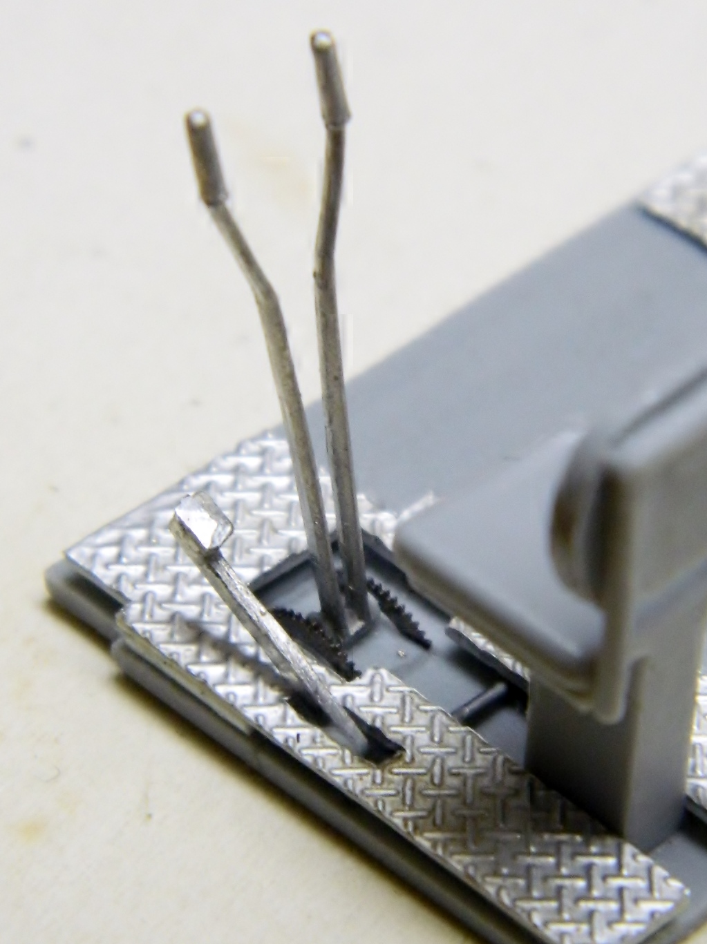
Next I started work on the various details of the control rods, levers, and linkages. Some of these parts are VERY small; all have to be removed from their casting blocks and trimmed before they can be used. I also drilled small holes and installed locating pins made from copper wire to align things and make the bond stronger when they’re glued:


Then the parts are dry-fit to check for fit and alignment (there’s a mistake here with the transverse rod that I didn’t notice at the time; you’ll see how I fixed that later once I realized it):
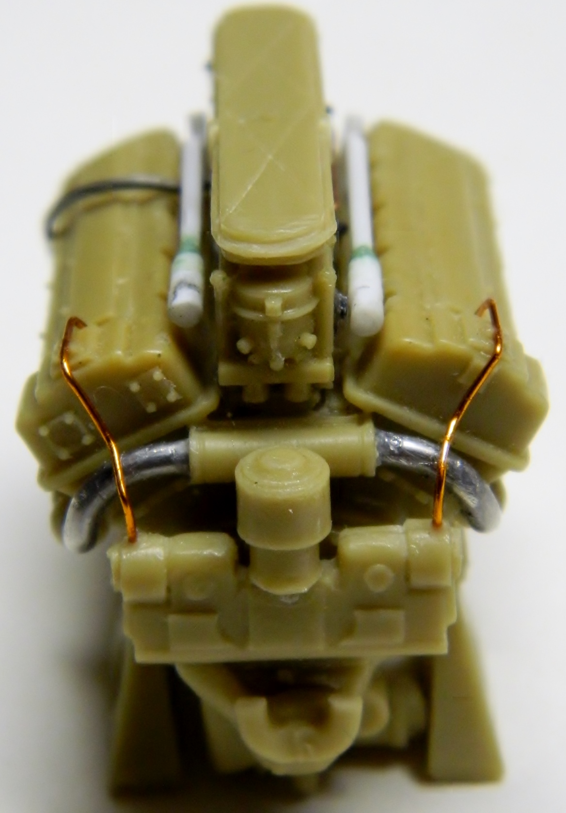
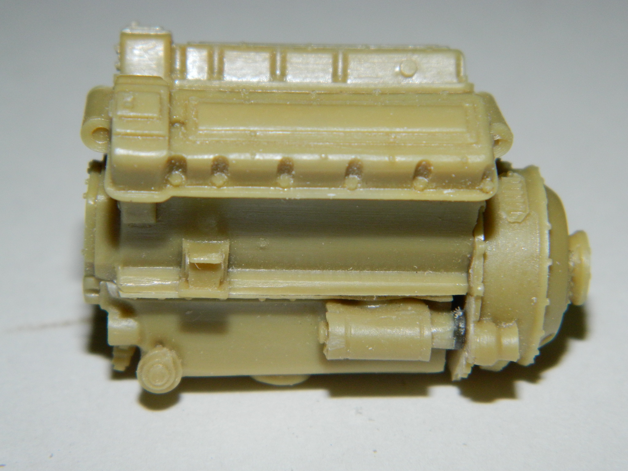
Because there’s only so much of really tiny things that these old eyes will abide at any one sitting (yeah, because those parts are ever so much larger), I went back to the engine and added the throttle linkage that goes to the driver (silver line), the ignition harnesses (copper lines) and the coolant manifolds:


Looking at reference photos, I saw that the floor in front of the driver and co-driver had diamond-tread plate sections, not the smooth floor of the resin part. I made a template out of a 3X5 card and trimmed it until it was a correct fit and then made a piece out of .020 sheet styrene:


But the floor in the driver’s area is raised (there are linkage rods, wiring, and other stuff that run underneath it), so I used some blocks of .020 styrene to raise it:
However, that’s smooth plastic, not diamond-tread. At the time I didn’t know where I could find sheets of diamond-tread in this scale (I do now) so instead I took a floor section from an entirely different kit that does have diamond-tread in this scale (Academy’s M3 Stuart) and using that very thick aluminum foil, I pressed it down on the kit part to copy the tread (using a small hammer and a piece of a bike inner tube to get that foil ALL the way down):


I took the smooth plastic floor I made, glued it onto the patterned foil, trimmed it, and did a dry-fit to check fit and appearance:


So yes…I know I’m crazy. 23 years ago when last I modeled, I used to collect all kinds of strange things because I knew I could use them in a model one day. This is a broken watch I took apart so that I could use the small pieces in a model or two (and yes, has been carried around with me of almost a quarter century because I might need it one day…today is the day):

Where the steering levers attach to the floor are toothed quadrants where the controls can be locked in place to keep the tank from rolling. As it turns out, one of these gears is just the right diameter for what I need, so I cut one into parts, used the old Dymo label tape as guides, and scribed slots for these to fit in:


Earlier I had mentioned I was using Grandt Line bolts for details; these are GL bolts (yes, the bolts are square and should be hexagonal – I tried to get the proper ones but though GL has a website, evidently they have no one who will ship an order – I placed one, waited a few days for confirmation, and never heard back despite repeated attempts to evoke any sort of response – it took some doing to find a vendor who sells these items but that took me some time to find – instead of holding up the build I used what I have and they don’t look bad or as wrong as they actually are):
The people who engineered this kit thought that nobody would see interior details which means there are no interior details. But now the interior will show and those details have to be added. The front of the hull on the Sherman tank was its final drive housing, or differential cover (mistakenly called a “transmission cover,” and it’s not; the transmission is inside the tank between the driver and co-driver). That cover/differential/transmission assembly bolted to the hull and those bolts are clearly seen through open hatches (which is how this will be displayed). Since they aren’t there, I had to go to reference photos to see where they are, how they’re spaced, and then put them there. It’s starts with one, one leads to two, and once those were in place, I ran a piece of Dymo label tape between them as a guide and started gluing very small nuts in place, and do that again for the other side (there are a lot more bolts, you’ll see them in subsequent photos):


Also visible through open hatches are the bolts that go through the hull and hold the suspension bogies to the sides of the tank. I finally figured out a way to get the spacing correct. Since the spacing of these fasteners are the same on both sides of the hull, I could cut the exterior detail off the donor kit, glue them to the inside of the build kit, and then use putty to hide all that. It starts with cutting the bolt pattern off the donor kit:
That piece was then filed until it was much thinner and then glued in place, using the hole for alignment and the edges puttied:


There was a bit of work to that, so for the other side, I tried something different. I used less of an addition and only the edges are glued. The center, which is really only there for alignment, I removed easily as it was not glued. Less putty, less putty removal, less work:


Back to work on the driver’s controls with much sawing of TINY parts, cleaning them up, and getting them to fit with each other. First the steering levers. The old tanks of WWII were steered by slowing down the track on the side you want to turn towards. Want to go left? Apply the brakes to the left track (and tanks are still steered that way, though now the controls are much different). These levers are connected through linkages and rods to brakes inside the differential housing. The AM set provided lead alloy metal parts for some parts and that’s what the steering levers, clutch pedal and arm, and accelerator pedal are (the clutch pedal needed to be reshaped):

Back to cleaning up the really small parts (of which there are more than a lot).
M4A3 (Tamiya) Build #5
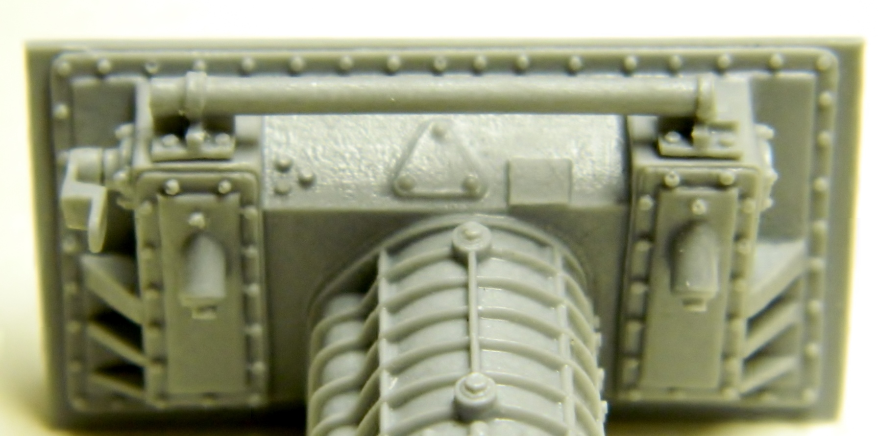
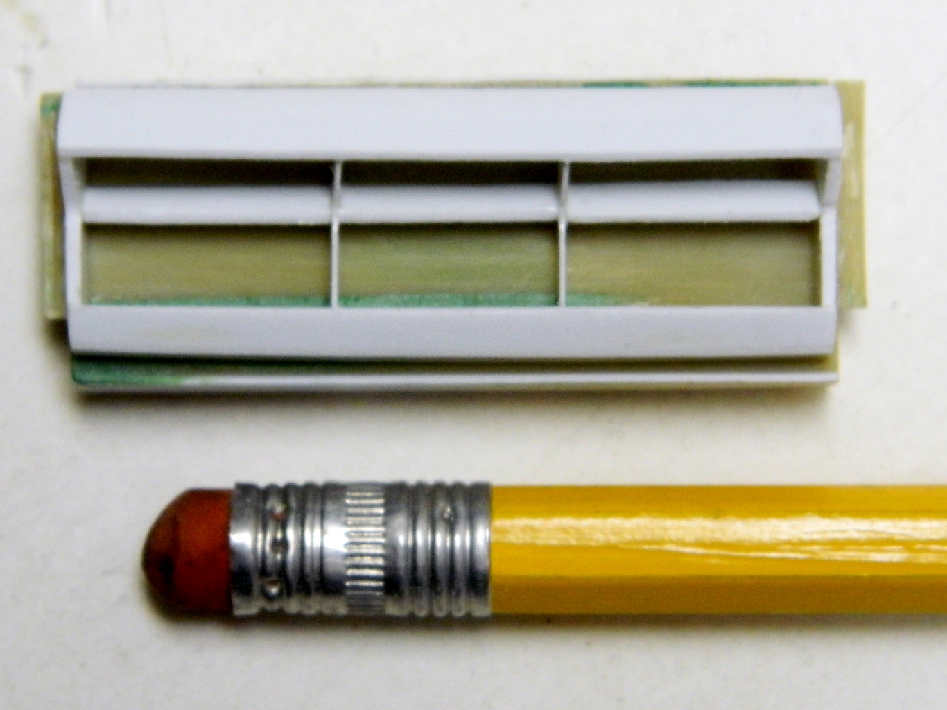
Now to get the ducting assembled with much dry-fitting along the way. I’ve found it easier when adding pieces that require a specific size to add the piece before trimming it. Once the glue has set, trim to fit. Much less hair-pulling that way:


With the basic structure of the deflector (because I don’t know what else to call it) set, horizontal sections need to be added. They follow the same curve as the top of the deflector so I checked to see if the left over plastic I’d vacu-formed would work and it looks like it does:
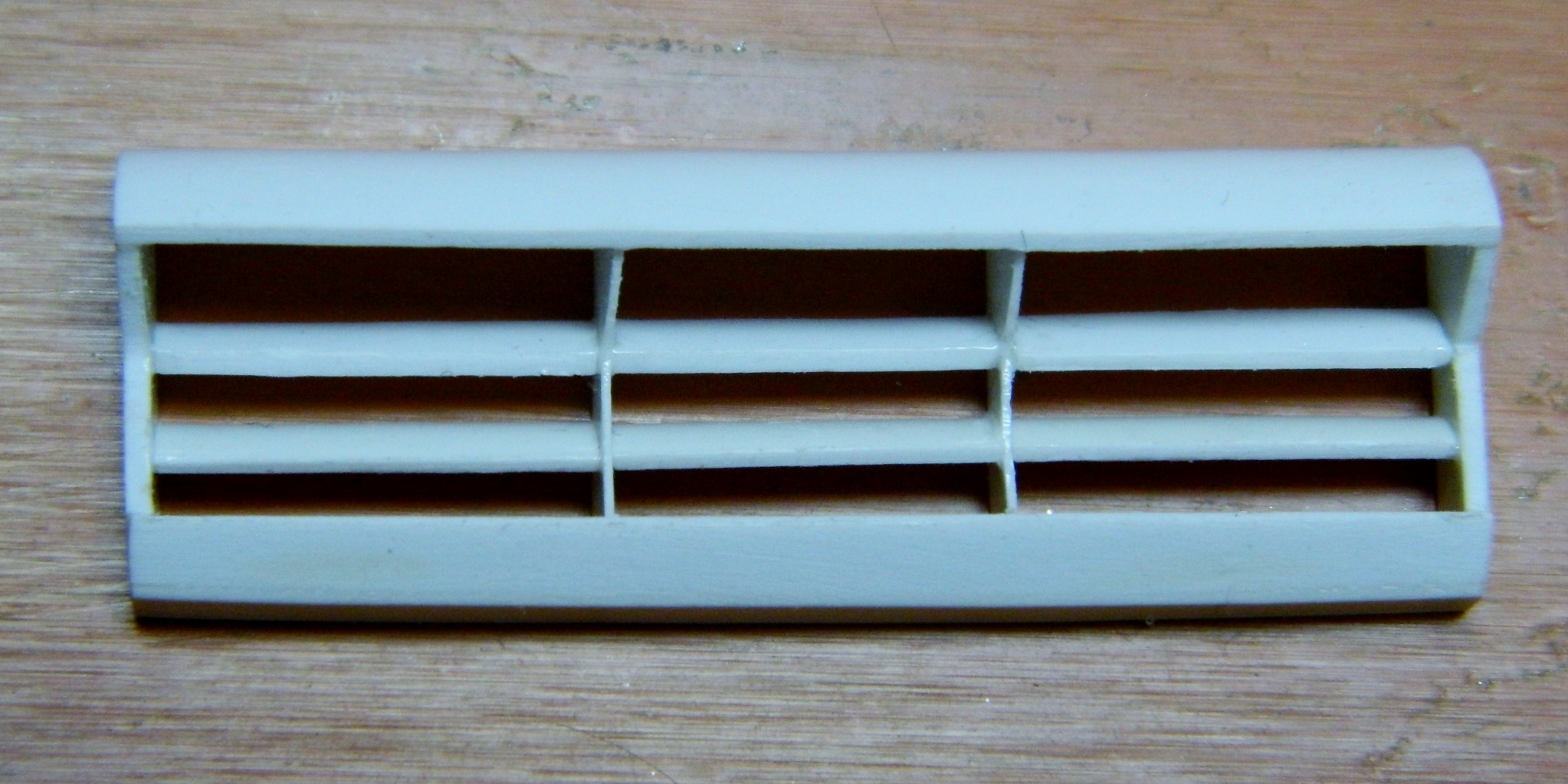
With the structure done, things need to be tidied up and trimmed:
In the course of dry-fitting the deflector to the back of the radiator bulkhead I dropped the Damned Thing. That would have been okay because it’s light and no damage would have happened to it if only my reflexes hadn’t gotten involved and grabbed the Damned (and fragile) Thing. So I had to repair it and the result isn’t quite as good. As it turns out, this part will be mostly (if not completely) hidden. So lest I drop the Damned Thing again, it gets glued to the radiator bulkhead:

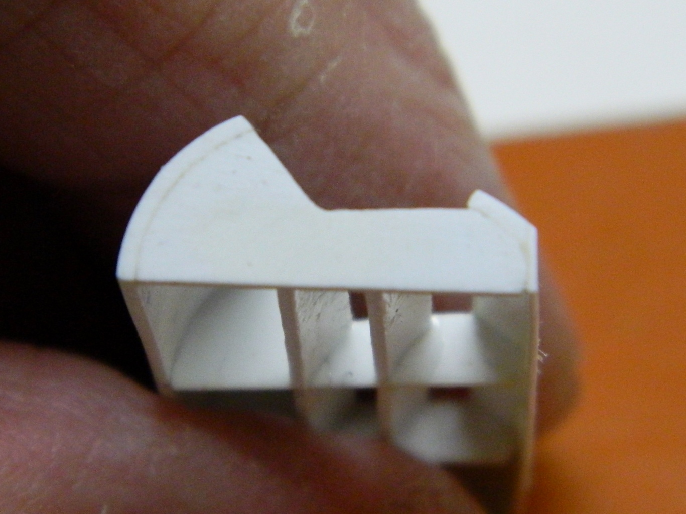
With that done, it’s time to attach it to the lower rear piece, correcting the inaccuracy of its angle:
There were alignment tabs cast into the resin parts that had to go. I still wasn’t entirely satisfied by the line created where the radiators meet the lower plate so I masked off the radiator openings and applied putty to the seam. Later on I will scribe the line back in:
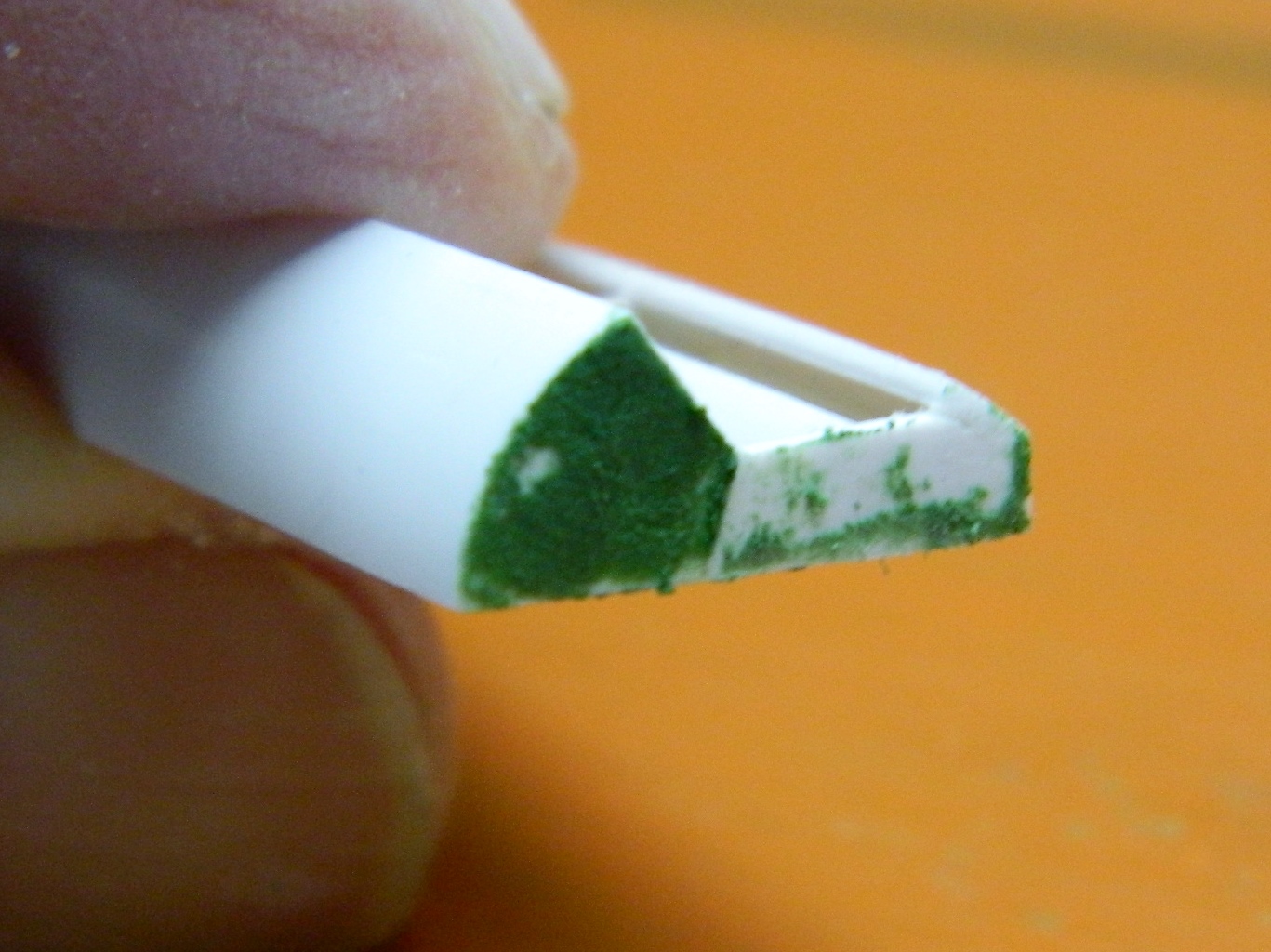
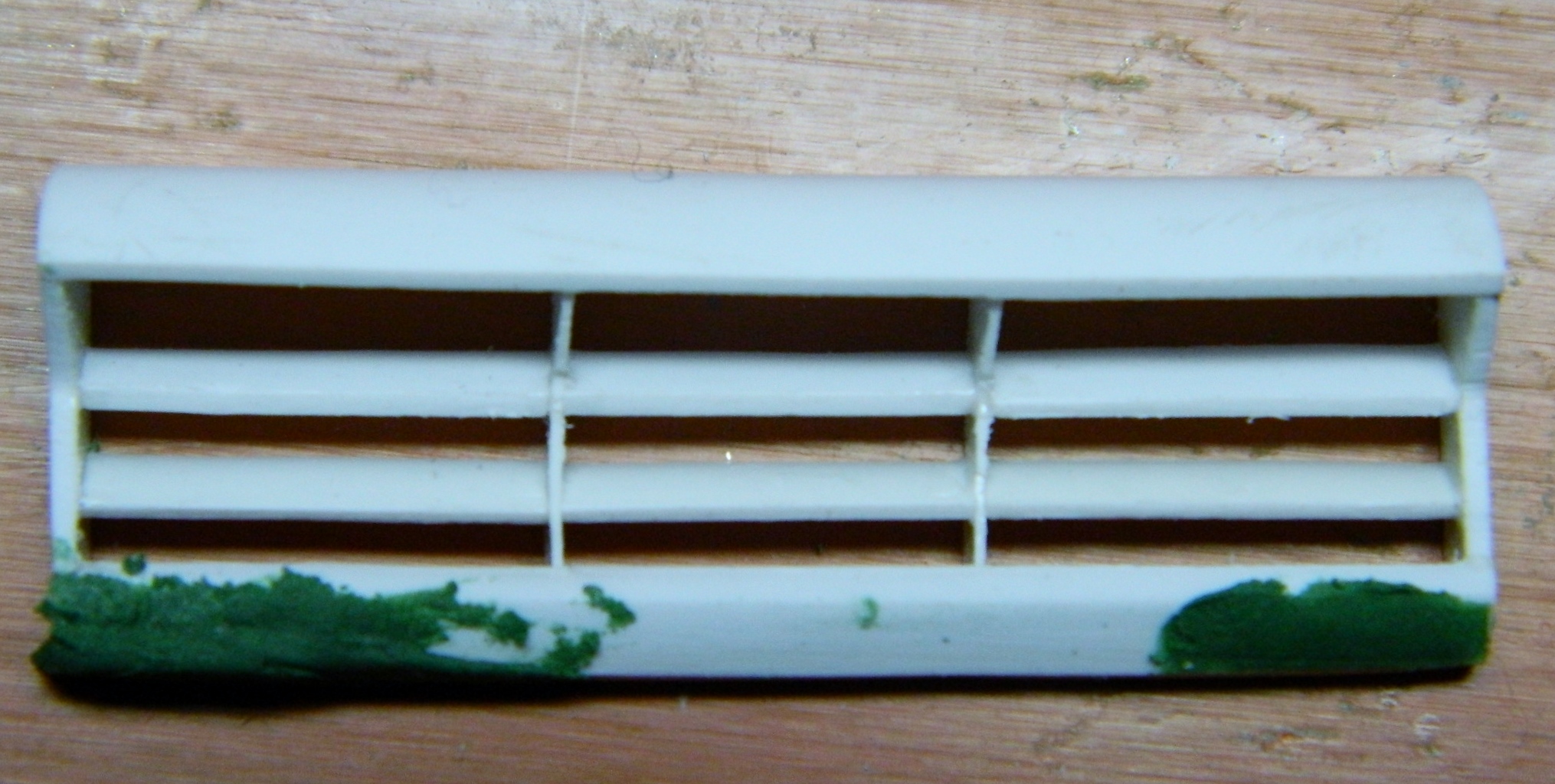
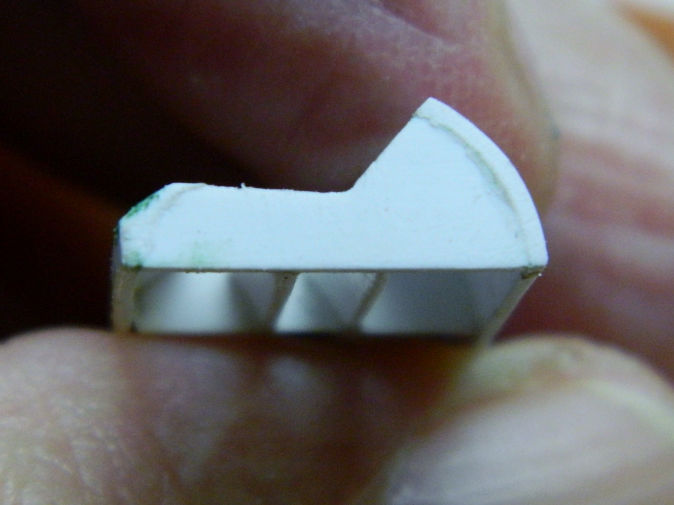
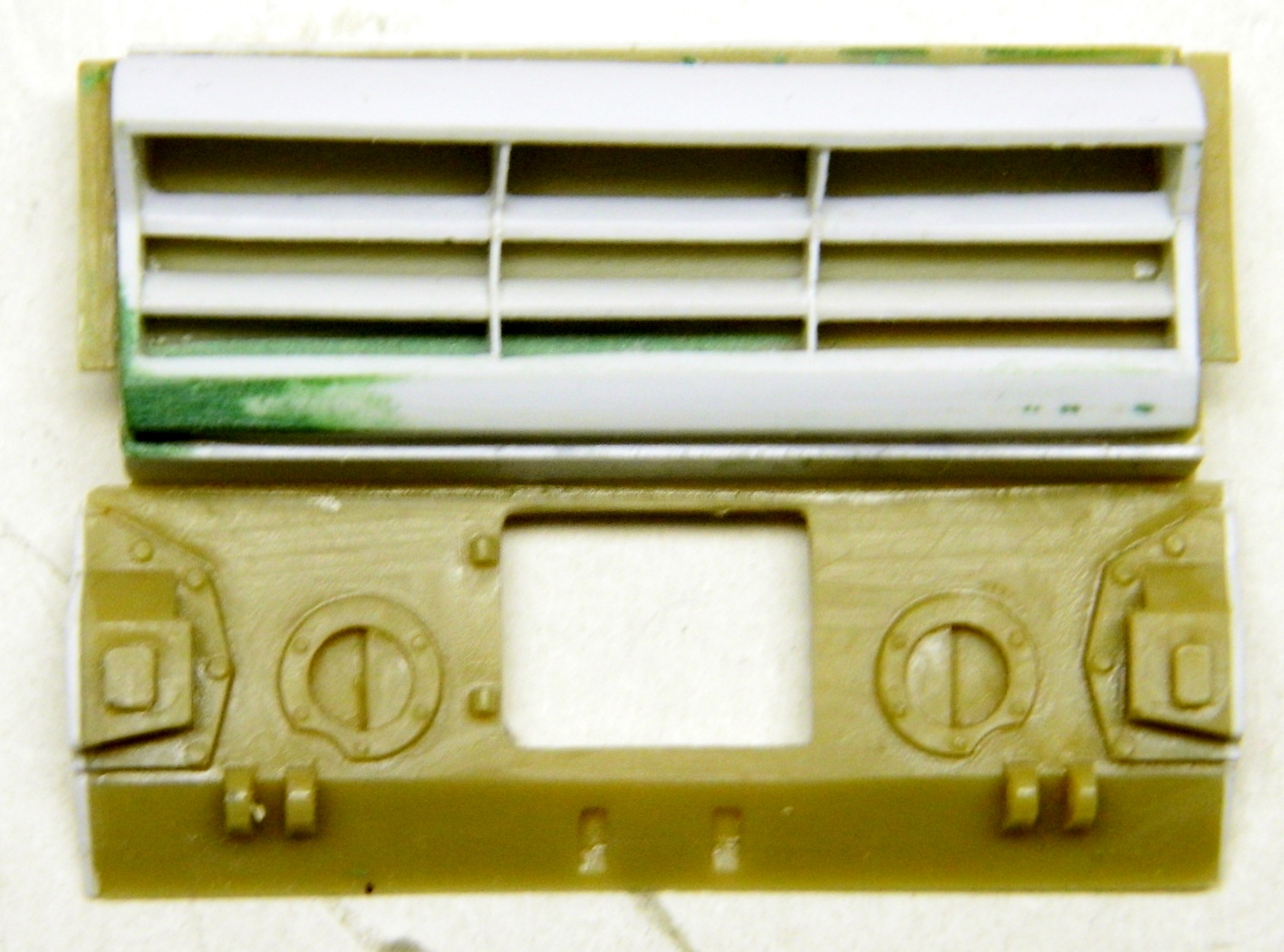
The kit part is in dark green at the bottom. There are “wings” on either side that I need to replicate on the replacement parts. Originally I thought I’d make them out of styrene but then realized that I already had the properly formed parts. Kit parts! So I’m going to measure, cut, and attach them to the replacement parts:
I aligned the bottom of the kit part to the bottom of the resin part and used a white colored pencil to trace the cut lines onto the kit part and made my cuts:

I don’t like butt joints; I find them to be too weak. When there isn’t any other attachment option, I prefer to add pins to not only locate the parts to where I want them but to also strengthen the joint. First I cut slots to “socket” the addition, then I added the pins (22 gauge wire):

Dry-fitting is also easier with pins, and dry-fitting, in case you haven’t noticed yet, is important to do, especially when doing modifications to parts or adding after-market parts. It’s SO much easier to fix fitment problems that way:

Yep…they sit right where I want them so they were glued in place.
Dry-fitting the assembled rear to the lower hull I saw that I had to add styrene to fill gaps between the hull and rear. I’m sure this will require tweaking later on but it works for now:

At this point I moved to the other end of the lower hull to address more fit problems. I have no idea what Tamiya’s engineers were thinking when they engineered this kit (I get into that in more detail in “Opinions, Reviews, and Tips” later on). My thought concerning the fit problem below is that the lower hull was an attempt at a one-size-fits-all part for their M4 kit. (That whole “economics” thing. ::spits::) Whatever their reasoning was, it left me having to fix gaps on either side of the lower hull where the differential housing attaches to the lower hull. I used styrene to fill those gaps:

M4A3 (Tamiya) Build #4
Now it’s time to finally address that outer radiator bulkhead and fix that. The drawings from my reference book are in 1/48 scale; ¼” equals 12”. And as it so happens, I just happened to have a 1/35 scale ruler. This is the difference in a scale foot:
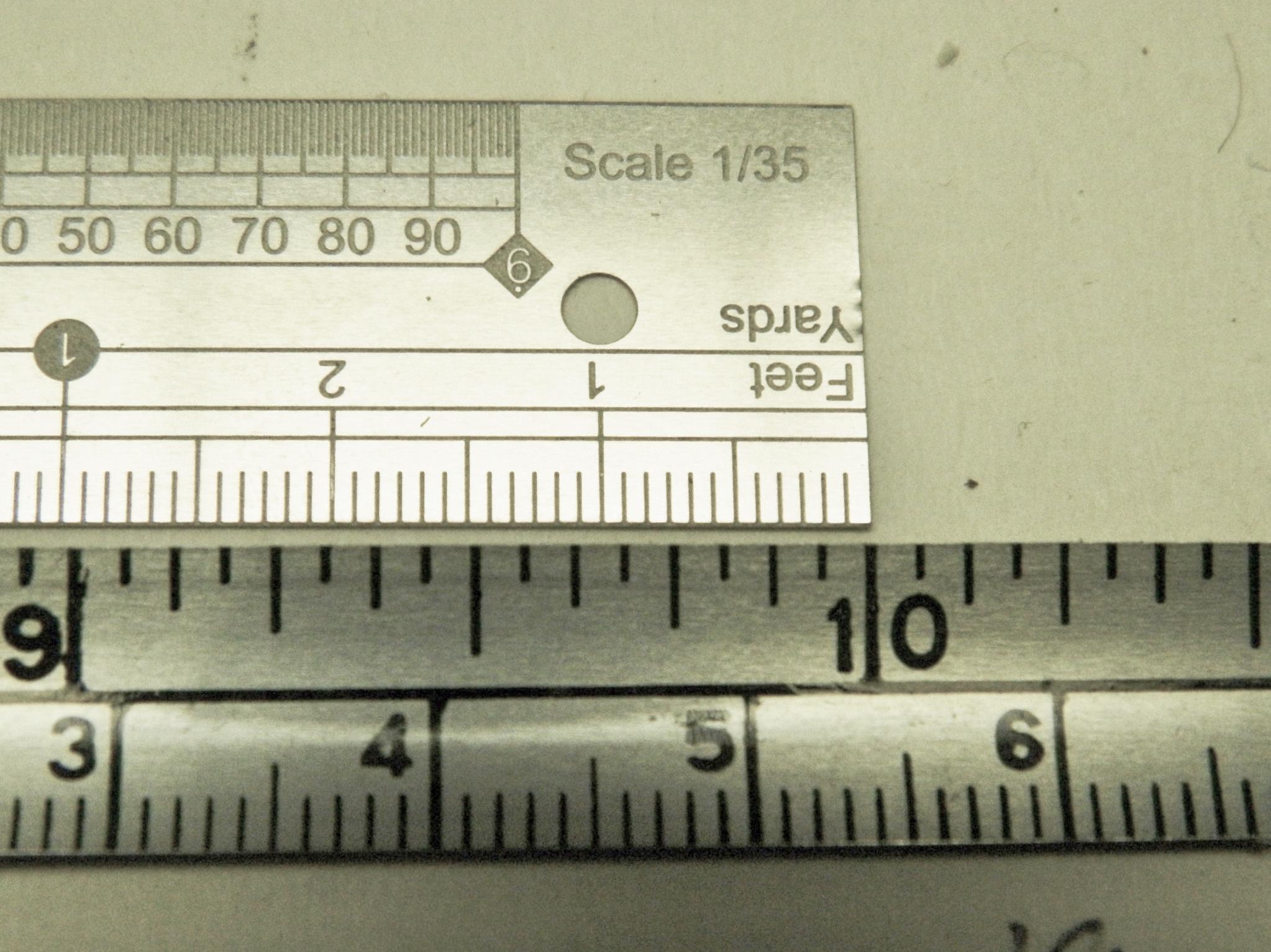
So how do I, a math phobic talking monkey, convert accurately? CUE THE PROPORTIONAL DIVIDERS:
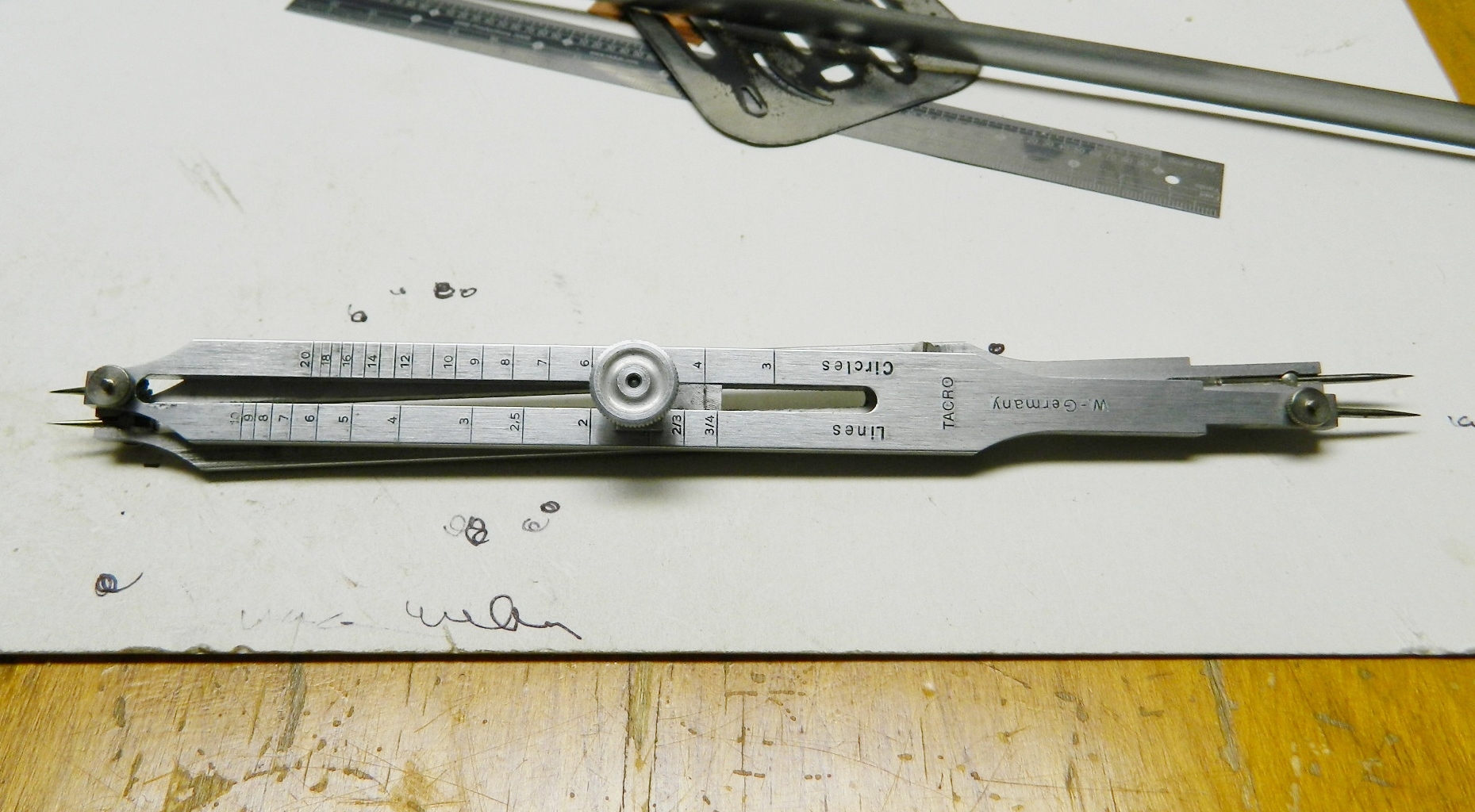
This is such a handy tool! The pivot will loosen and move. By positioning the pivot correctly, these dividers can transfer and convert a given dimension from one scale to another accurately. It starts by aligning the long tips to the larger scale and keep dicking with the position of the pivot until the small tips match the reference, which in this case is a foot:


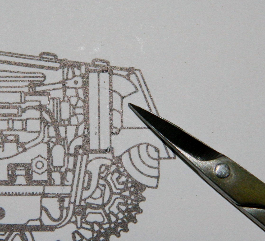
Now I can take a measurement from a 1/48 scale drawing and reproduce that length in 1/35 scale. The scissors are pointing to the piece I need to replicate, the ducting that’s mounted on the rear of the radiator bulkhead:
I decided to make a template using 010 brass shim stock (because it’s sturdier), then cut the template out, trace it onto sheet styrene, then cut that out:

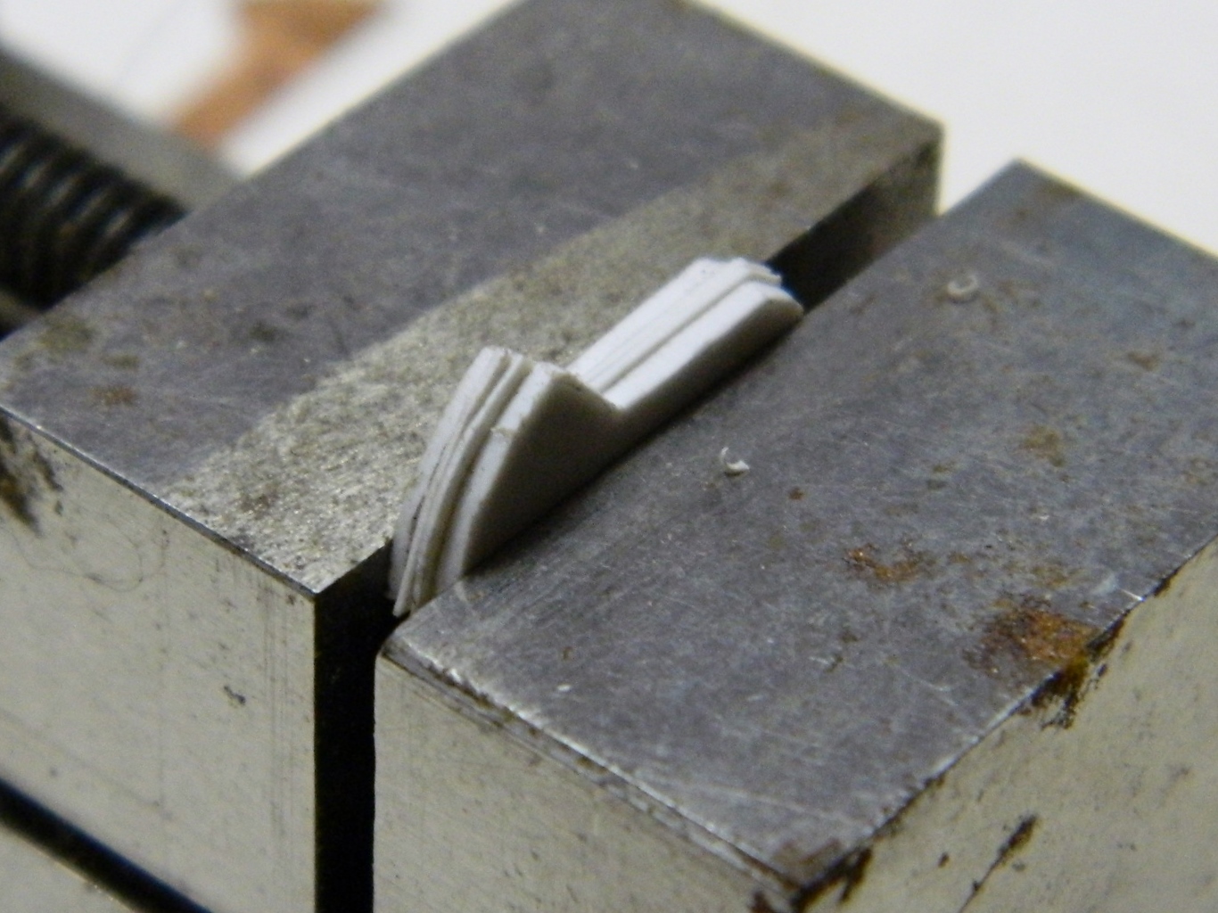
I need four vertical partitions. The outer ends look like they’re about twice as thick as the inner ones so I used .020 sheet plastic for the ends and .010 for the inners. I aligned them and then clamped them into a vise so that they would all be shaped the same:
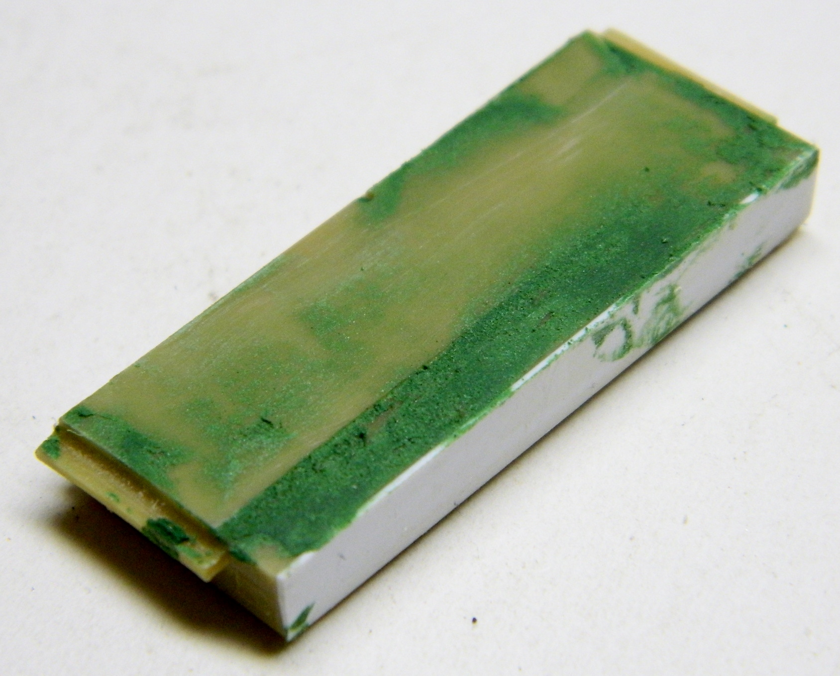
With the vertical partitions formed, it’s time to address the radiator bulkhead. I laid down a coat of modeling putty so that the final shaping would result in a flat surface without having to take too much material off to get there. If you think you’re going to need to add putty to a resin part, check before you commit to that course of action; not all resins will bond with putty:
The lateral partitions of the ducting are curved so I need to create an even curve in plastic. I’d briefly considered doing the curved sections out of brass stock but I think plastic doesn’t solder well to that so I decided plastic would be better. How do I curve plastic evenly? CUE THE VACUUM MOLDER (you’ll find more information about that in “Side Projects” under “Vacuum Molder”). As it turned out, a half-inch dowel offered just the curve radius I needed:

Then I pried the wood out of the plastic, trimmed roughly around the edges, trued up one side, and used my small miter box and razor saw to cut things to the approximate length:
Next I needed a more exact straight-sided piece. I knew that flatness would be relative to the sides of the ducting assembly, so I started by using a machinist’s square to align an end and glued it on (I used a file as my surface plane because I knew it was flat):
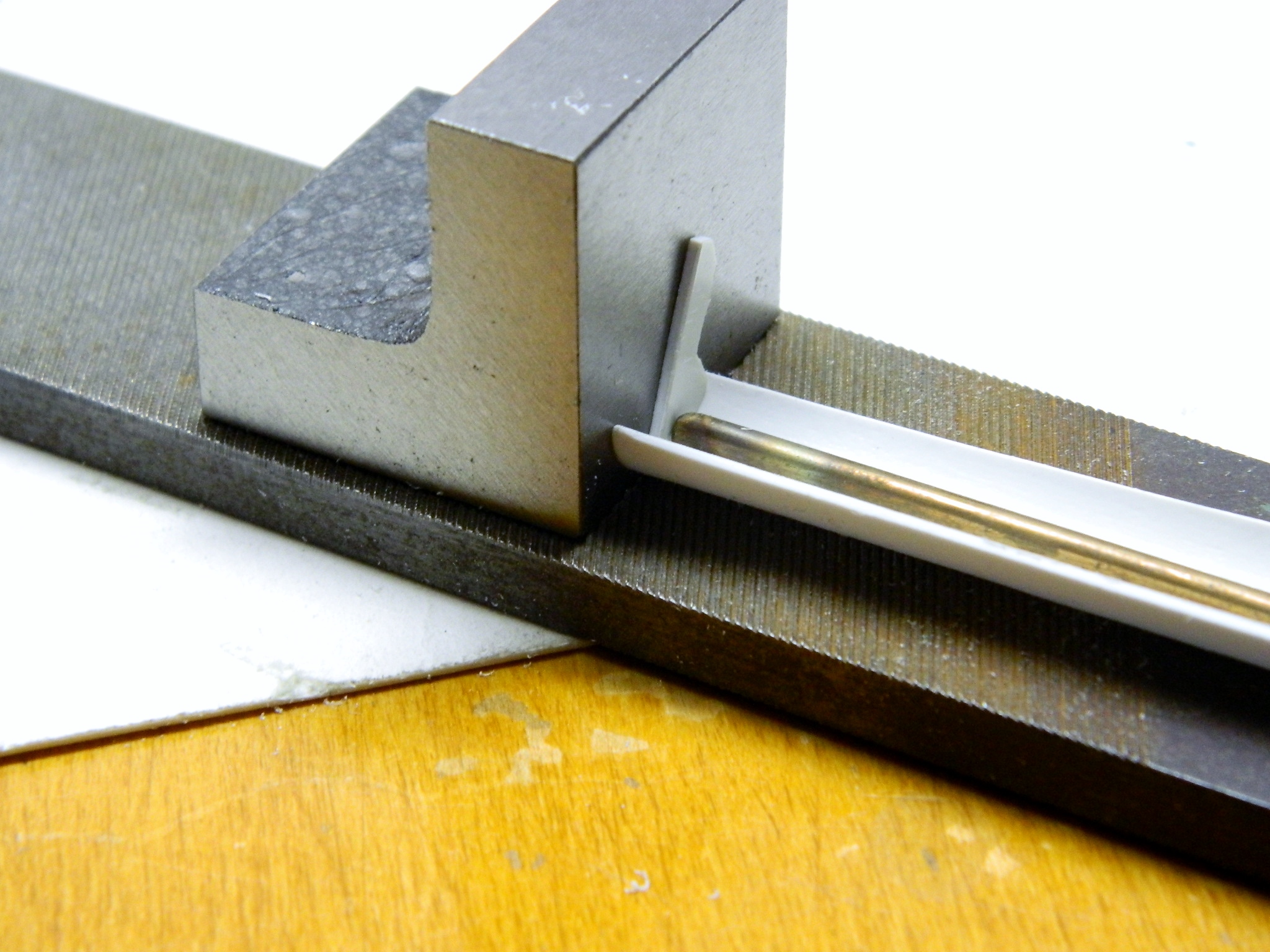
I’ve found it’s fairly easy to add things to an existing structure. Things get interesting when one has to build the structure to attach things to. Since I have one end glued on, I taped the pieces to the back of the radiator bulkhead and glued the other end on:

While that glue was setting up, I attached the bolt strip to the top of the differential housing. This part is one casting on a Sherman, that meant I had to fill in the small (but perceptible) gap between the strip and the housing. Somewhere I figured out that if I didn’t get putty INto things, I didn’t have to figure out how to get the putty out, so I masked off the area and applied the putty:

Now we let that cure…
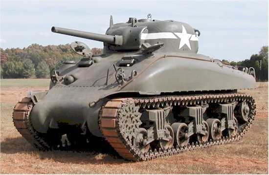
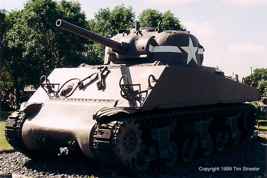
Sherman – A Brief Overview
The M4 Sherman tank. Much loved, equally maligned, common wisdom states that it was not intended for the uses it was put to.
Yeah, most of them had low-velocity guns that couldn’t penetrate the armor of a Panther or Tiger tank at range, and yeah, the Panther and Tiger could light up (literally) a Sherman at ranges a Sherman could not reach. However, Panthers and Tigers combined only made up about 30% of the German armor the Allied tank crews faced after Normandy. The Sherman could go toe to toe with any German armor up to and including the Pkw. IV series (though the Pkw IV with the long-barreled 76mm did out range the Sherman’s 75mm).
Having said that over three years ago, subsequent research has shown that what follows and I had written back then is mostly inaccurate:
“But in line with the Armored Command’s battle doctrine, the Sherman was never intended for armor-on-armor engagements; that’s what tank destroyers were intended to do. The tactical application of the Sherman was a holdover from the WWI philosophy of using armor as infantry support like a mobile pillbox to break through enemy lines and create havoc and destruction behind the lines, or as a mobile fortification covering infantry on the advance.”
For an interesting look at the Sherman, its history and role, check out this YouTube video:
So it looks like I’m not the only to think the M4 series is a good tank! (And while you’re at YouTube, look for, “Oh bugger, the tank’s on fire.” QUITE fascinating.) The one major advantage the Sherman had over the Panther and Tiger (other than sheer numbers available in the field) was that it was reliable and a lot easier to work on. Panthers and Tigers were much more complicated machines and of all the terms tossed at the Sherman, “complicated” is not one I’ve encountered.
Being an evolutionary design, it carried over many traits of the M3 Lee…both bad (high profile, thin armor) and good (a well-developed drive train with robust components that are widely interchangeable). Its turret traverse would spin a turret faster than most German tanks; getting the first shot on target makes survival easier, and given that 70% of its armored adversaries weren’t Panthers (or Tigers which were MUCH rarer), that first shot stood a good chance of ending the encounter.
The major reason a Sherman would light up so easily and burn was not because it was gasoline-fueled, it was discovered to be the result of where the main gun ammunition was stored in the “dry-stowage” hulls where the ammo was stored high on the inside hull, leading to “wet-stowage,” where the ammo is encased in water jackets and stored on the floor of the hull. With dry-stowage hulls, any shot that penetrated would likely result in setting off the stowed ammo; wet-stowage hulls cut down on that happening drastically.
By the end of its production run with the M4A3E8, though the armor was still thinner than its adversaries, a great many of its problems were sorted out, it had an adequate gun, and the ride of the last suspension design was a lot smoother. The Army liked the A3 series enough to keep it in service after WWII and a number of them saw duty in Korea (and note the comment in the above video regarding the M-26 versus the M-4!).
There were about 50-55,000 of them made; as one clever sod once stated, “55,000 Shermans and 54,999 different from all the other ones.” That’s because parts interchangeability was profound. The transmission of a Sherman built in 1941 would fit a Sherman of an entirely different variant built in 1945 (as would many other major components). Disabled tanks would be scavenged for parts in the field to keep less damaged Shermans in service and fighting.
Some Shermans (M4 and M4A1) had a Cyclone radial engine (a holdover from the M3 line of medium tanks and was the reason the hull of the Sherman had such a high profile), some had the Chrysler “multi-bank” engine (M4A4) which was actually five engines built around a common crankshaft; go ahead, try routine maintenance on that one without pulling the power-plant, some had a 1000 cu. in. Ford V8 (M4A3 and M4A3E8), and though most Shermans were gasoline-fueled, a few were even diesel (M4A2 and a radial-engine diesel, the M4A6 of which only 75 were built).
Most had a low-velocity 75mm gun. Some were armed with a 105mm howitzer. Finally, a high-velocity 76mm gun was fitted (the 76mm, oddly enough, wasn’t as popular as the 75mm was, mainly due to the absence of a good high-explosive round). And all of that doesn’t take the British Shermans, called “Fireflies” into account with the 17 pounder gun. (And I haven’t even mentioned what the Israeli army did with them! Google M51.) There were even flamethrower variants the troops called “Zippos.” Some tanks had cast upper hulls, some had welded flat plates (of two varieties) and some had the forward upper cast hull welded to flat plate rear upper hulls. Most turrets had what’s called the “pistol port” (though it was actually intended to toss empty cannon brass out of) though many did not. Earlier turrets had a low bustle and no loader’s hatch; later ones had a high bustle with a loader’s hatch (and there were two variants of the loader’s hatch!). Early turrets had a flat, two-piece commander’s hatch, and later ones had a “vision block” cupola with a single hatch. Some turrets had applique armor over the gunner’s position, some had it cast in at the foundry. Two different gun mantles were fitted, early and late (of course) with an entirely different one for the 76mm gun. Early transmission casings were three-piece units bolted together (another M3 holdover), later ones had a one-piece cast casing and those could have rounded or pointed noses. And all of these parts were interchangeable!
And I haven’t even mentioned the assault variation of the Sherman M4A3E2 with a ton (actually, a couple of tons) of thickened armor or self-propelled artillery built on the Sherman chassis…
Three different types of suspensions, five different designs of tracks, some with applique armor over ammunition storage bins (dry-stowage, which had one design of engine air cleaners) some without (wet-stowage with different design and location of air cleaners), two different turrets, three different guns (75mm, 76mm, 105mm howitzer) and none of that takes into account individual crew modifications or field-expedient modifications (like the hedgerow cutters welded to the nose to keep them from hanging up on the Normandy hedgerows after the D-Day landings at Normandy) OR the specialized variants like the dual-drive Shermans intended for amphibious landings, tank retrievers (fitted with cranes), and on and on and on.
All the above just scratches the surface of what was done to the “basic” Sherman tank. So what the hell is a modeler to do? Model 54,999 tanks? (Even I’m not quite that crazy.)
I decided that I would do maybe five. An M4 (welded-plate upper hull), two M4A1s (cast upper hull armor), an early one with direct-vision slots and a later one without, all of these with low-bustle turrets and the Cyclone radial engine, the M4A3 which has different welded flat-plate armor from the M4 (less of an angle to the front glacis plate which was easier to build and had less places an incoming round would find a vertical surface to penetrate) and the V8 engine (made by Ford, 1000 cu. in., 500hp and 1100 lb/ft of torque from off-idle to 2500 rpm, aluminum, DOHC, four-valve per cylinder, twin carbs) and the high-bustle turret with the loader’s hatch, though there were also low-bustle turrets with loader’s hatches, too. And finally an M4A3E8 wet-stowage 76mm with the advanced suspension, considered by many to be the best of the Shermans (I may also do one of the British Firefly variants).
I decided to start with the M4A3… It was the variant the Army liked most and retained for use and upgrades after WWII.

M4A3 (Tamiya) Build #1
Tamiya makes an adequate kit of the A3 and this is the base for this build:


Since I haven’t done a model since 1991 and I wanted to ease back into the pastime, I decided I would add a COMPLETE interior to a kit that was never designed to have one. This means adding an engine and engine bay, a crew compartment, and all the turret details, not any of which were engineered to work with each other. (Let’s start easy, eh?)
One (of many) things I discovered is that not only is the state of the art for after-market (AM) detail sets MUCH different than it was 24 years ago, so is the Internet. I can find references (photographic and written) that were unavailable Back Then. So unlike Back Then, I don’t have to scratch build everything I want to add (as in, start with a pile of bits to make all the gizmos that a tank is full of).
So I started with the engine bay. There’s a Belgian company, Verlinden, that makes really beautifully-modeled AM sets for all sorts of models and one of them is the Ford engine. From the box art:
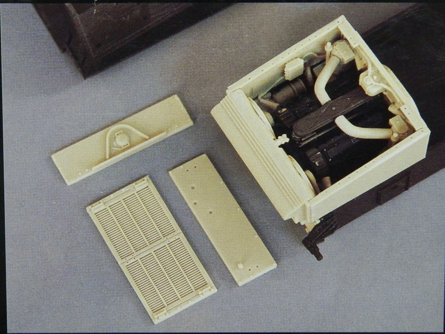
Most of the parts are resin (works about the same as fingernails) and this shows what the AM set includes:

So I started assembling the engine. The first step is separating the parts from the casting blocks:

When dry-fitting pieces together, I saw that the starter motor didn’t quite reach the bell housing, so I added a piece of sprue from my bits-box using superglue:

While the glue was setting, I saw/filed/sanded the exhaust manifolds free:

Then I attached the modified sump (the added piece, dark-colored on the lower right, will get trimmed later):
Dry fitting showed me that I’d trimmed one carb too closely so I had to add resin back (the tweezers are sitting on a lazy susan which makes aligning and gluing so much easier):


Fitted and trimmed the added plastic to discover that it doesn’t line up as it should. Short of remaking the entire starter, I realized that few would even see it much less realize it was “off” so I left it and glued the bell housing/clutch on:
Then I saw that the water pump had a major part of the cooling system that did not actually reach the engine, so I took some sprue, heated it over a candle, and once it was…well…plastic, I pulled gently trusting my Mk I Eyecrometer to get the diameter close (larger is easier to fix than smaller).
Good ol’ Mk I Eyecrometer nailed it on the first pull, so that was glued and set aside to cure:

Trimmed the added resin on the carb with a razor saw:


Then I added what looks like an air cleaner (it’s not, those are elsewhere in the engine bay, it’s actually a plenum chamber) and carbs to the engine as well as the modified water pump (later I had to snap the plenum off as I put it on backwards, lest you think this is one unbroken chain from a pile of parts to Modeling Glory):

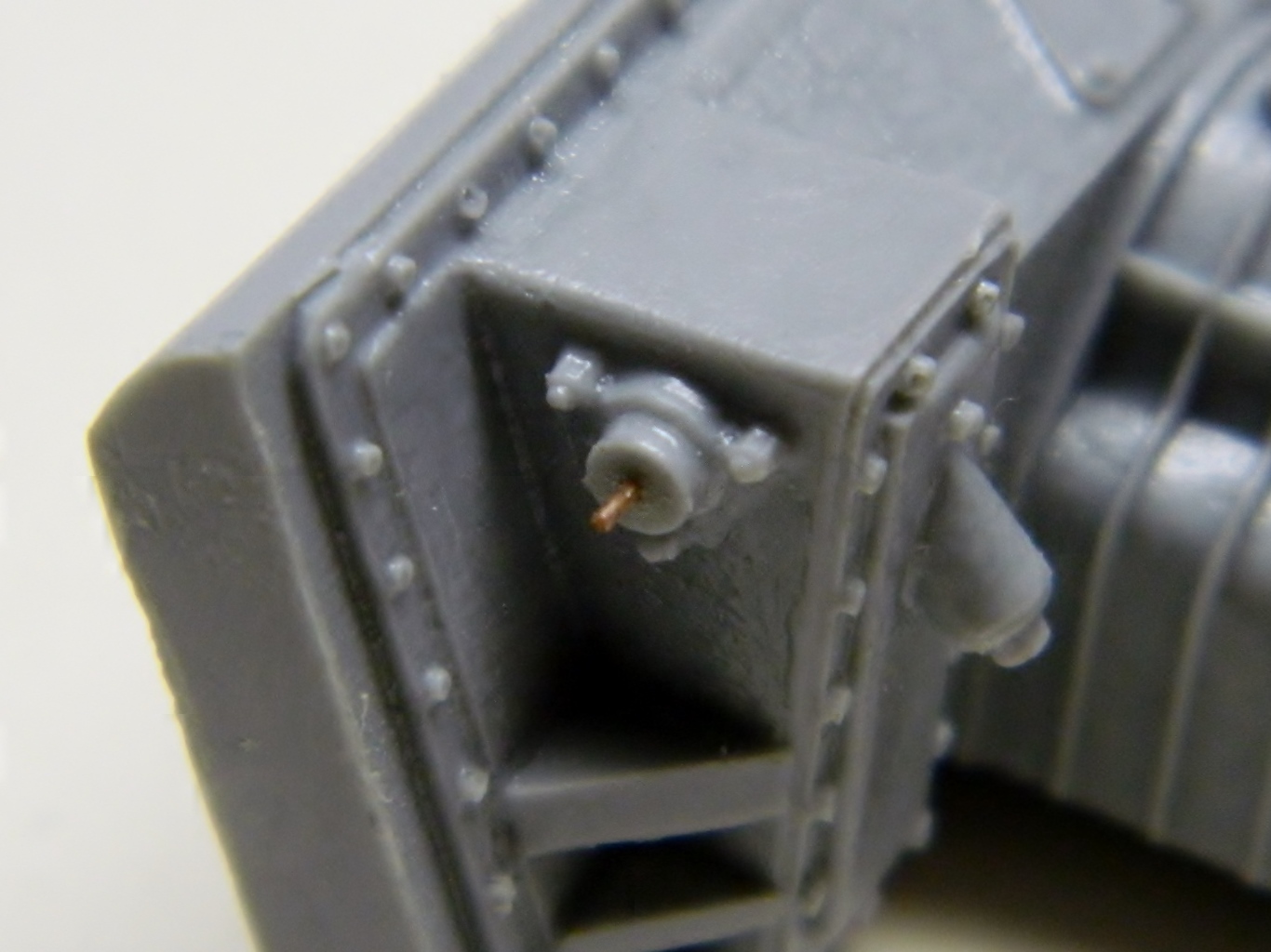
In looking at reference photos, there is a fuel pump on top of the engine that the AM set didn’t provide. In the above photo, the round thing under the plenum is the oil filler; the fuel pump is just as obvious, so I decided I’d need to build one. I spent a few minutes whining that I’d sold my Unimat lathe because it was SO much more precise than the lathe I have now…and then I realized something. This is plastic, not metal. I didn’t need a lathe; I needed something that I could clamp a piece of sprue into and spin slowly (otherwise the plastic melts). Enter the variable speed drill:


With the basic shape of the pump done, it was time to add the details. I added the shafts of the bolts using lead wool (just like steel wool only lead…how odd…available from plumbing supply and A LOT easier to work than copper…gah…or plastic…annoying). Then I glued a piece of plastic to the side where the fuel line from the pump goes to the carbs. I tried a couple of ways of adding the fuel line and it became quite evident that butt-gluing (don’t go there…like you just did) wouldn’t work (not enough surface area for a secure bond) (you’re still there…aren’t you) so I drilled it out and will use a length of solder of .032 diameter as the fuel line because it’s easy to bend, maintains that bend, and is structurally sound:

To replicate the bolts on top, I drilled the locating holes slightly, shaved sprue into an octagonal form (like the bolt heads I’m trying to replicate), and used the tweezers on stands to align and glue. I’ll trim them to size later (later on I would use Grandt Line styrene bolts for something like this but at the time I didn’t have them):
I wanted to add the magneto assembly next. I discovered that the back half of them weren’t modeled and since they would be easily seen needed to be. I used some of the cut off pouring stubs so make things easier to see:

Since that worked well, I did the other side the same way.
