I ordered another AM resin set for the crew compartment. Wet-stowage Shermans had a very different interior (the first one I bought was for a dry-stowage tank). Stowed ammo was kept in water-filled boxes so that a (highly likely) penetrating shot didn’t ignite stowed ammo (which made the tank explode and burn). This set has not only the fighting compartment details but also the turret details:
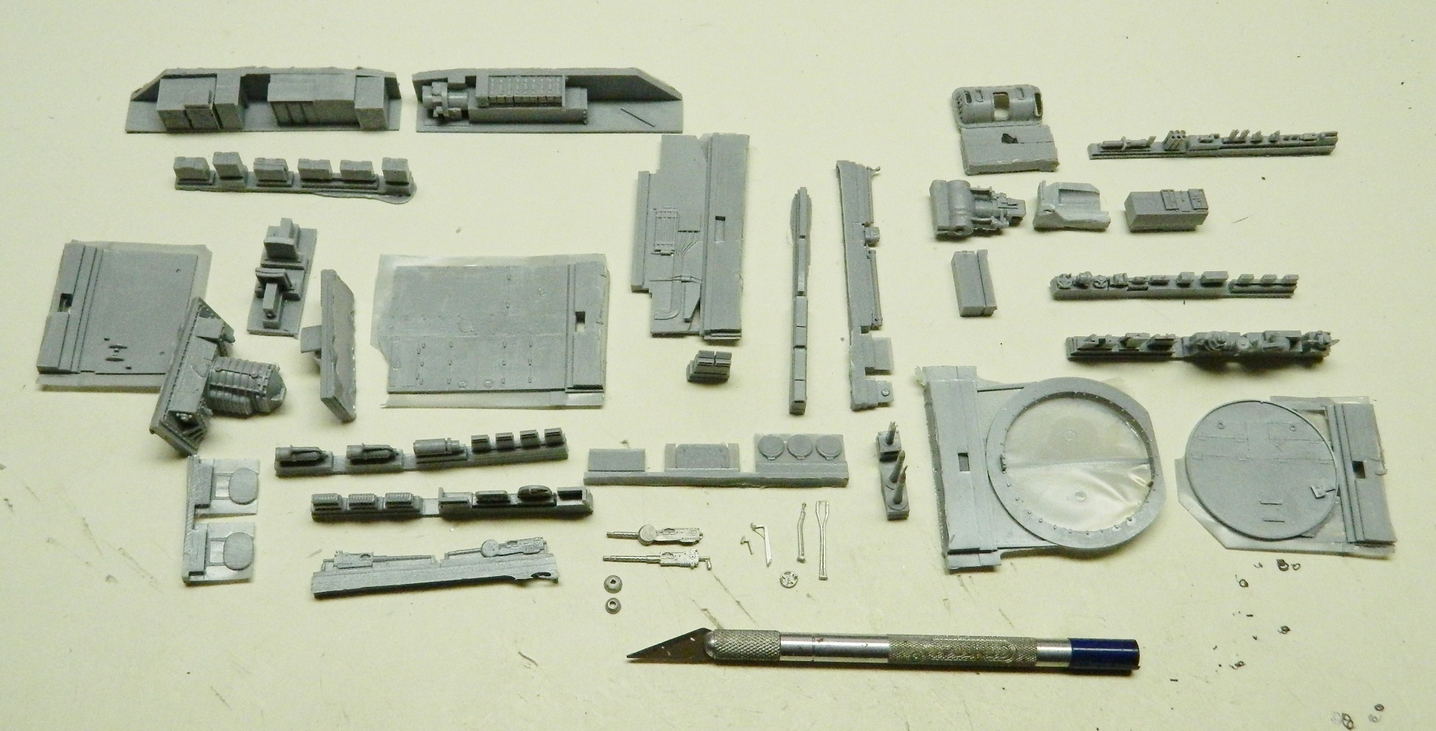
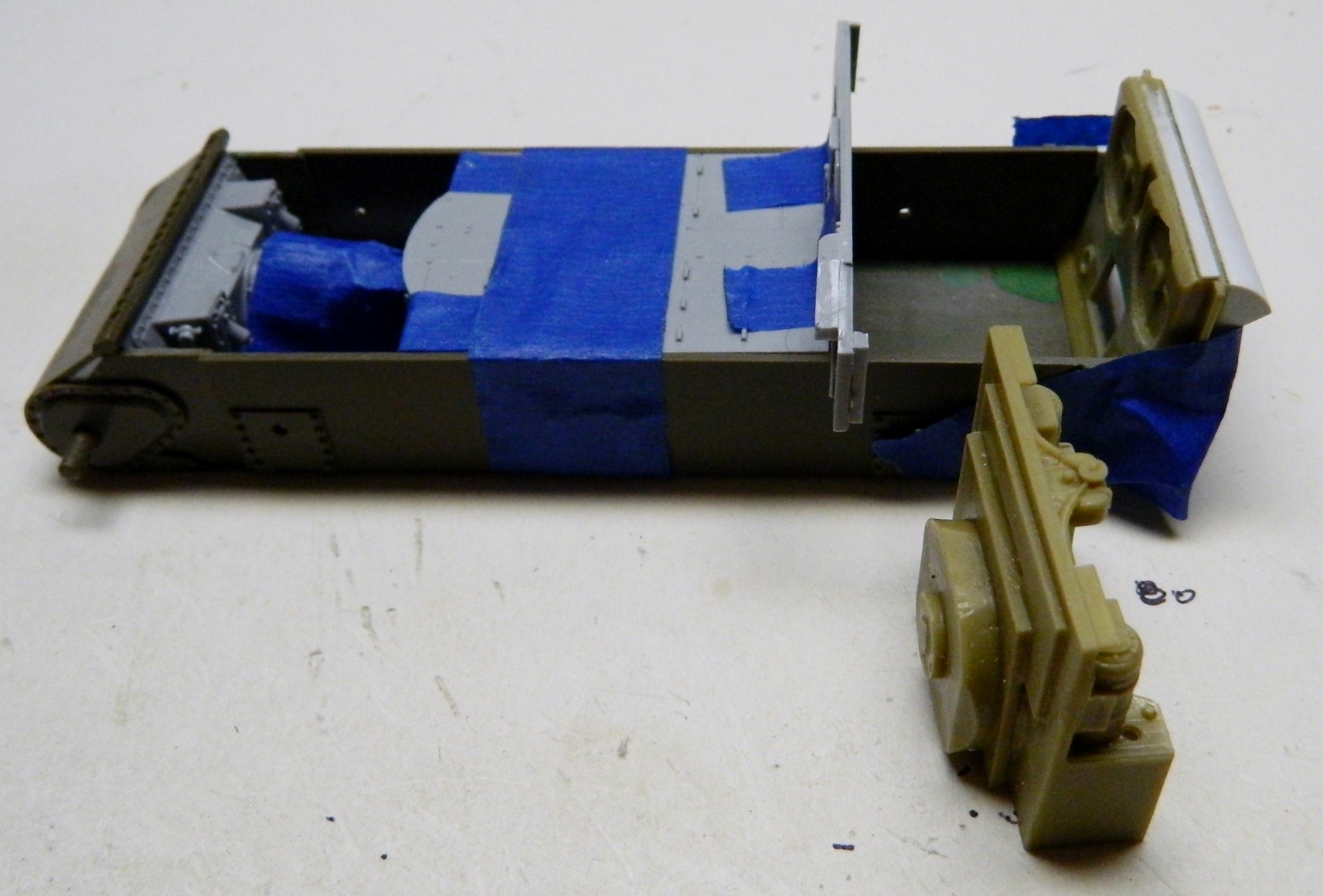
So now I have three different manufacturers; Tamiya for the tank, Verlinden for the engine bay, and Tank Workshop for the crew compartment. I decided to dry-fit some of the crew compartment because it all has to fit inside the hull (and I can see immediately that there will be fitting problems between the engine and crew compartments competing for space, but that’s for another day):

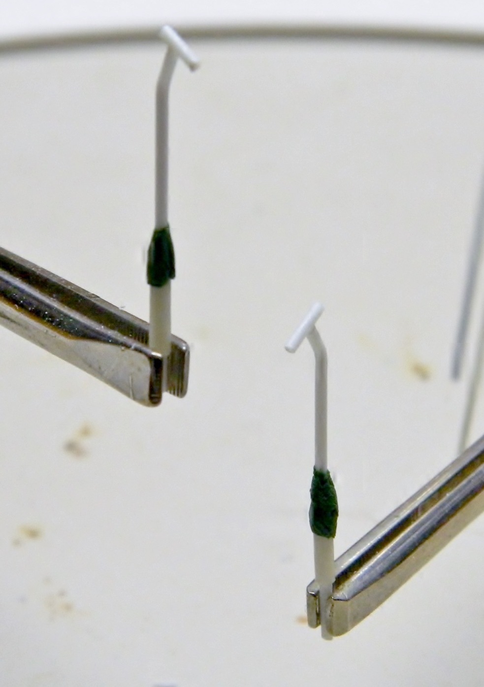
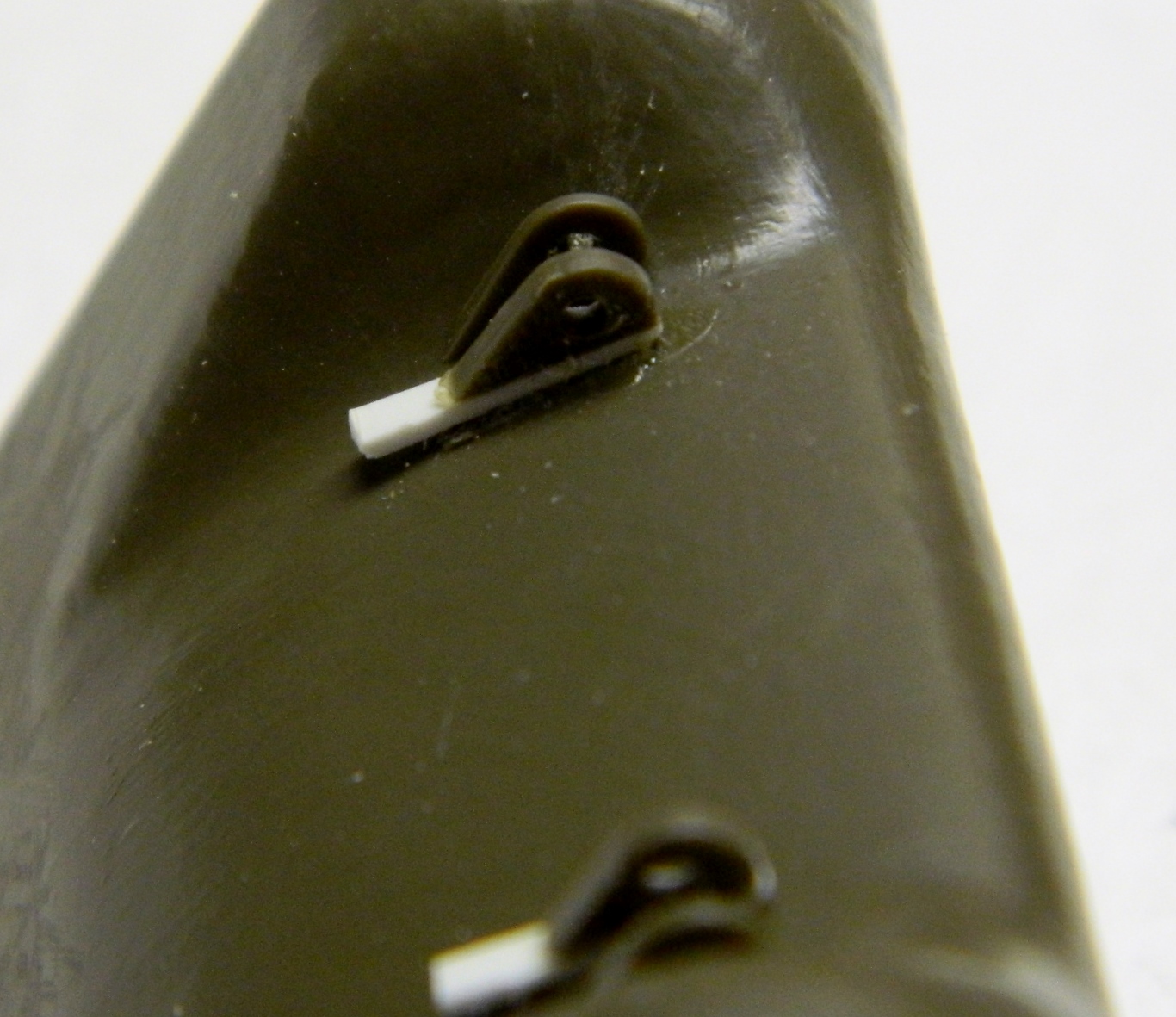
While the back of my brain worked on what to do next back there, I wanted to fix something that needed to be done due to the limitations of injection molding. The front tow hook mounts. There need to be holes drilled in them. But because of their location and the shape of the part, there was no way I could get in there with a bit to drill them out. So I had to remove them. But the kerf of the saw (the width of the cut made) meant I had to replace the thickness with styrene, so once I had the tow points removed, I added .010″ (.254mm) styrene:
Once the holes were drilled out, I trimmed the sides of the added styrene, glued them back into place, and filed and sanded them:

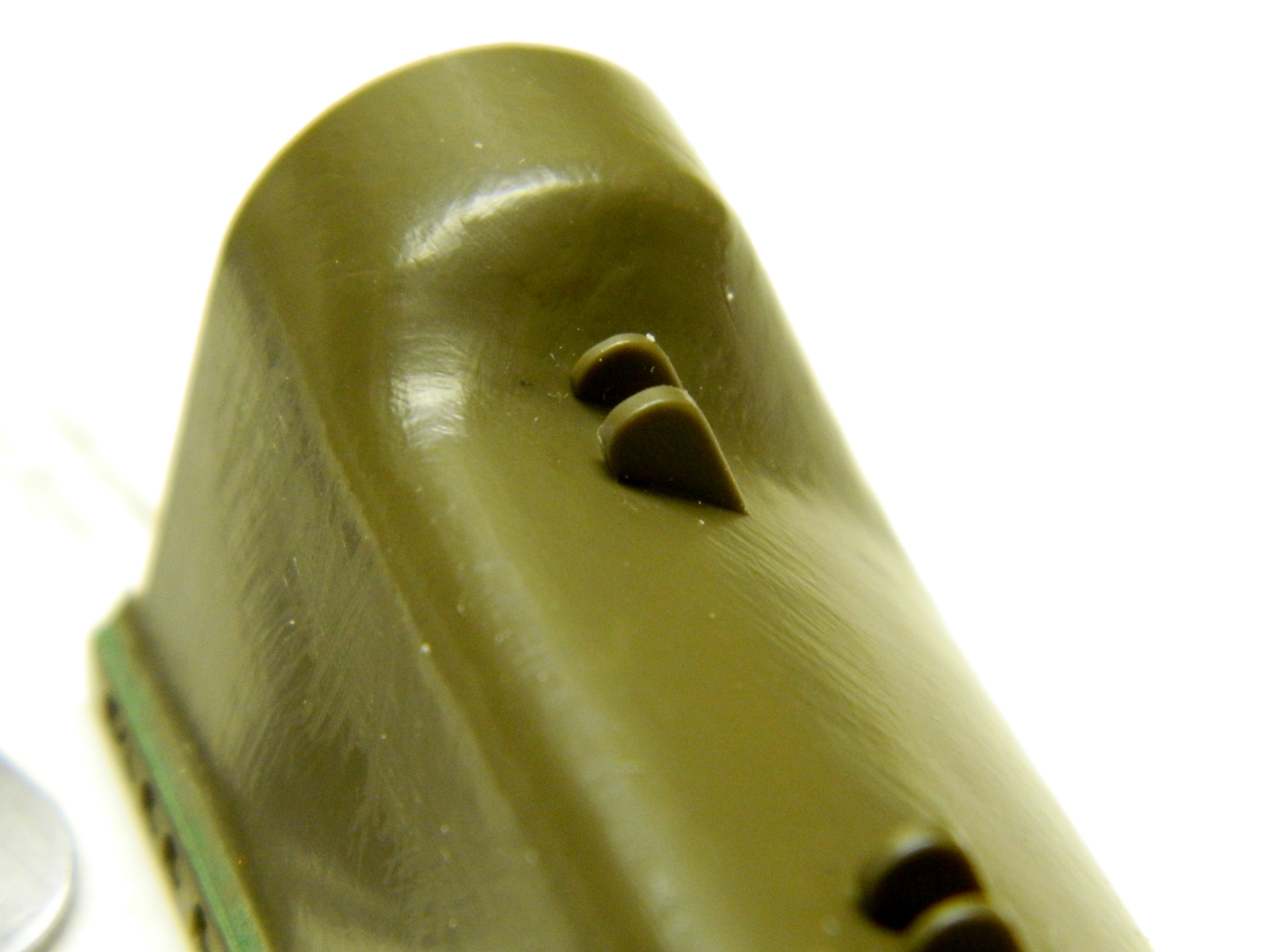
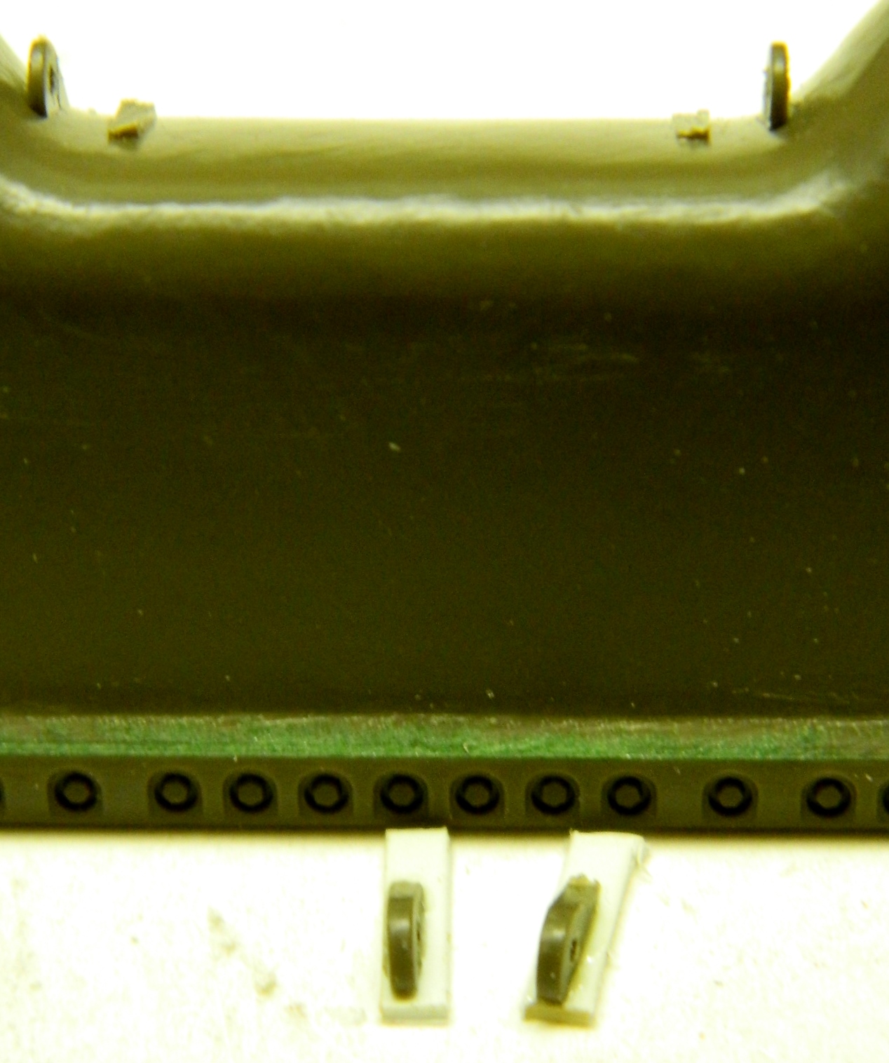
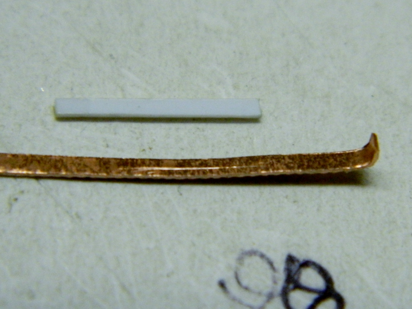
While I was working on the front towing mounts, I decided to add something that was a common field modification. Steps were welded to the nose at the towing points to ease mounting the tank. I had started to use .010″ (.254mm) styrene but decided that .010″ (.254mm) brass shim stock would hold up better:


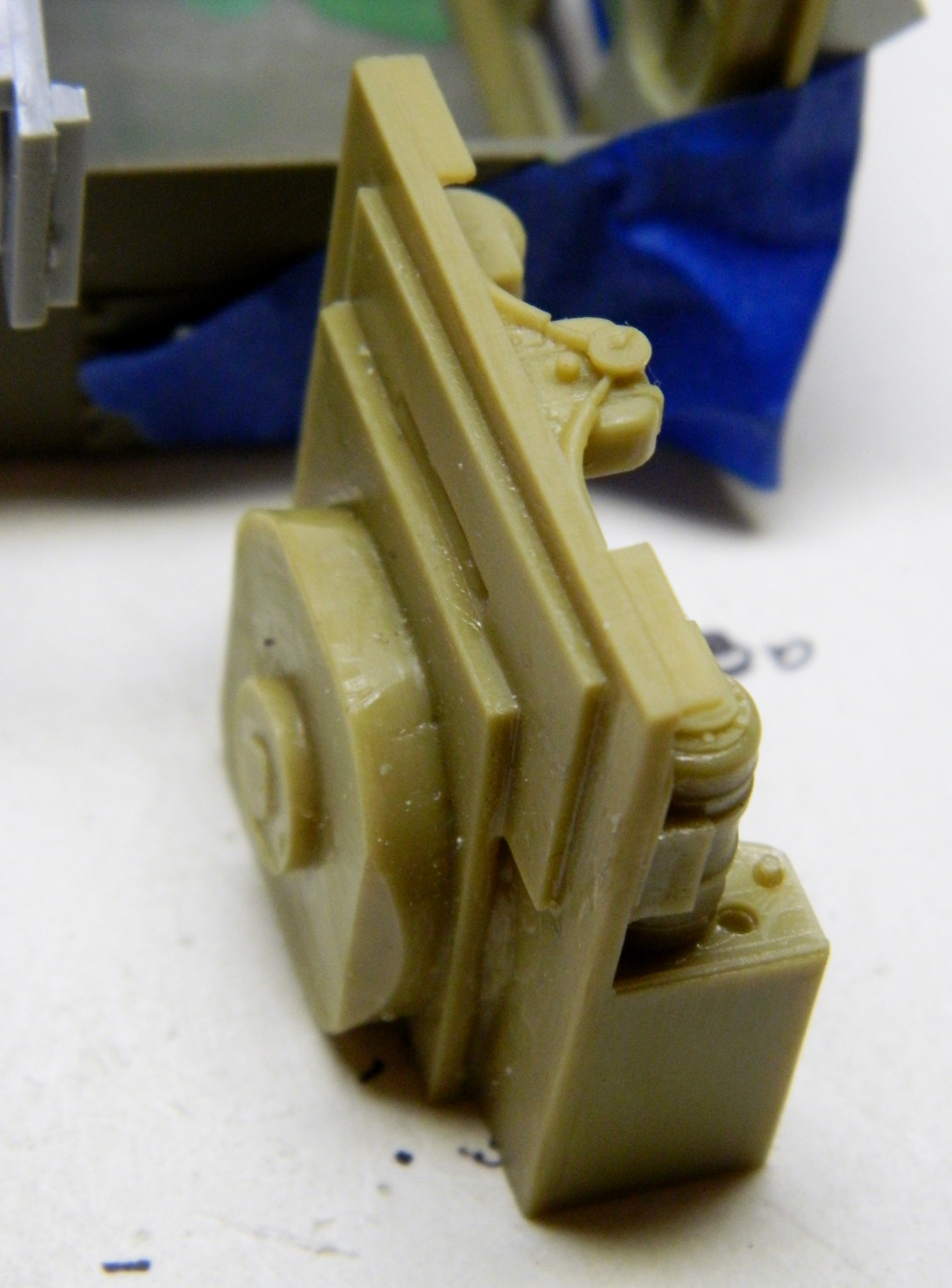
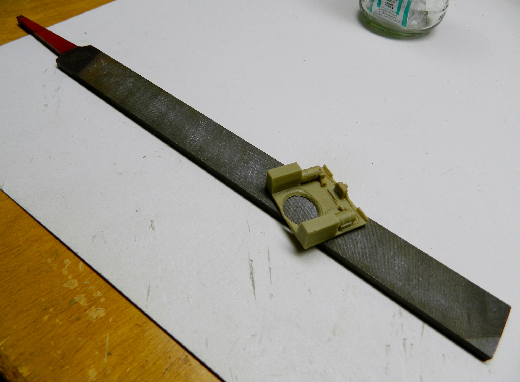
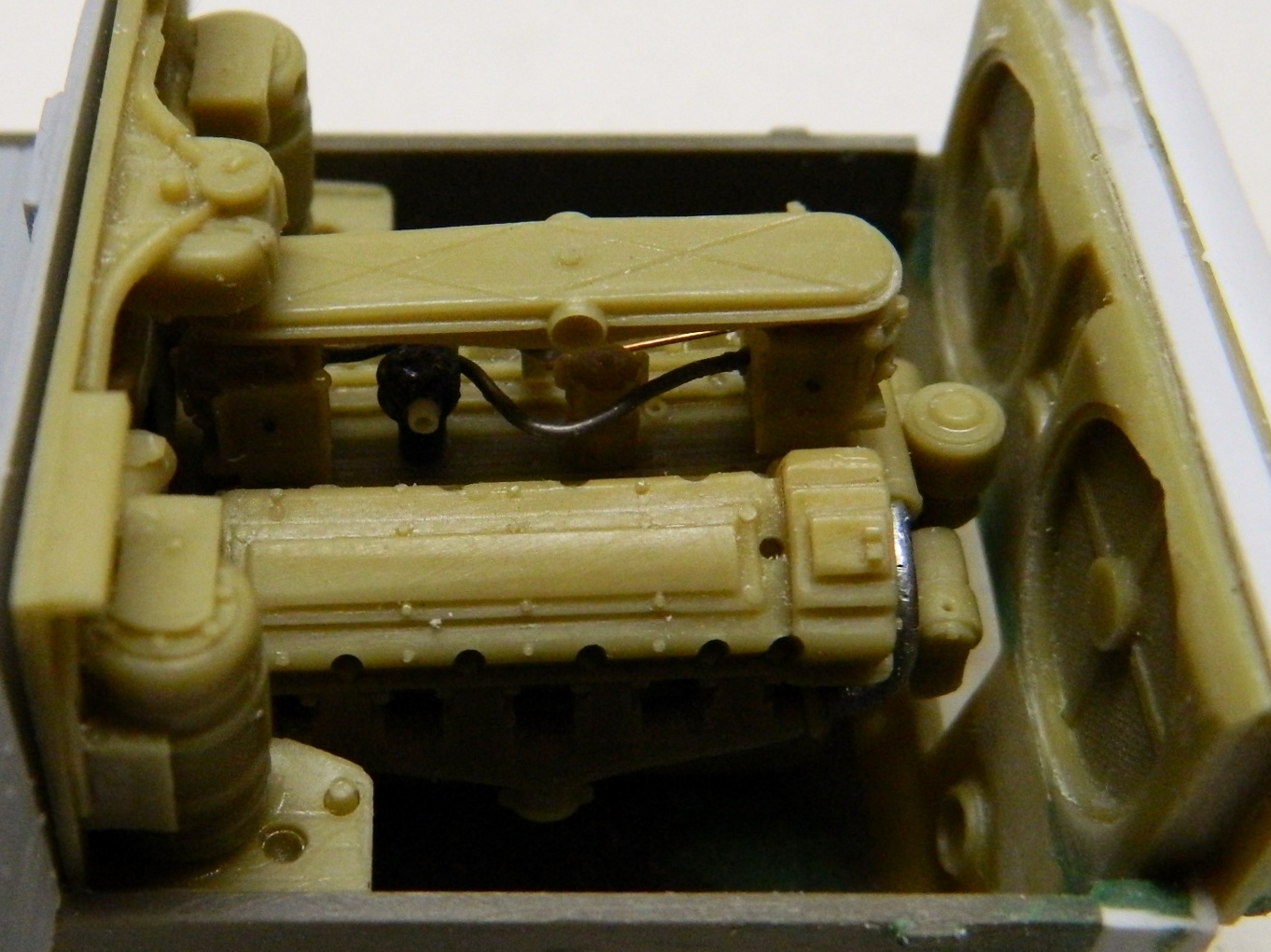
Next I wanted to work the interior parts so that both crew and engine compartments would fit in the same hull. And many hours of dry-fitting begins. First I realized that the large blocks of resin on the back of the engine bay’s forward wall (the tan part, lower right) needed to come off. It didn’t fit at all with the rear crew compartment bulkhead:
There was a lot of resin that had to be ground away and I knew that would put a ton of dust into the air. Yeah, I wear a mask, but I would still get that dust on everything so I decided to take a box, cut a hole for the vacuum nozzle, and do my grinding (with a multi-speed Dremel set on its lowest speed) with the vacuum going:


With the bulk of the excess resin removed, I used a file to bring it down some more (in a much more controllable, albeit slow, manner):
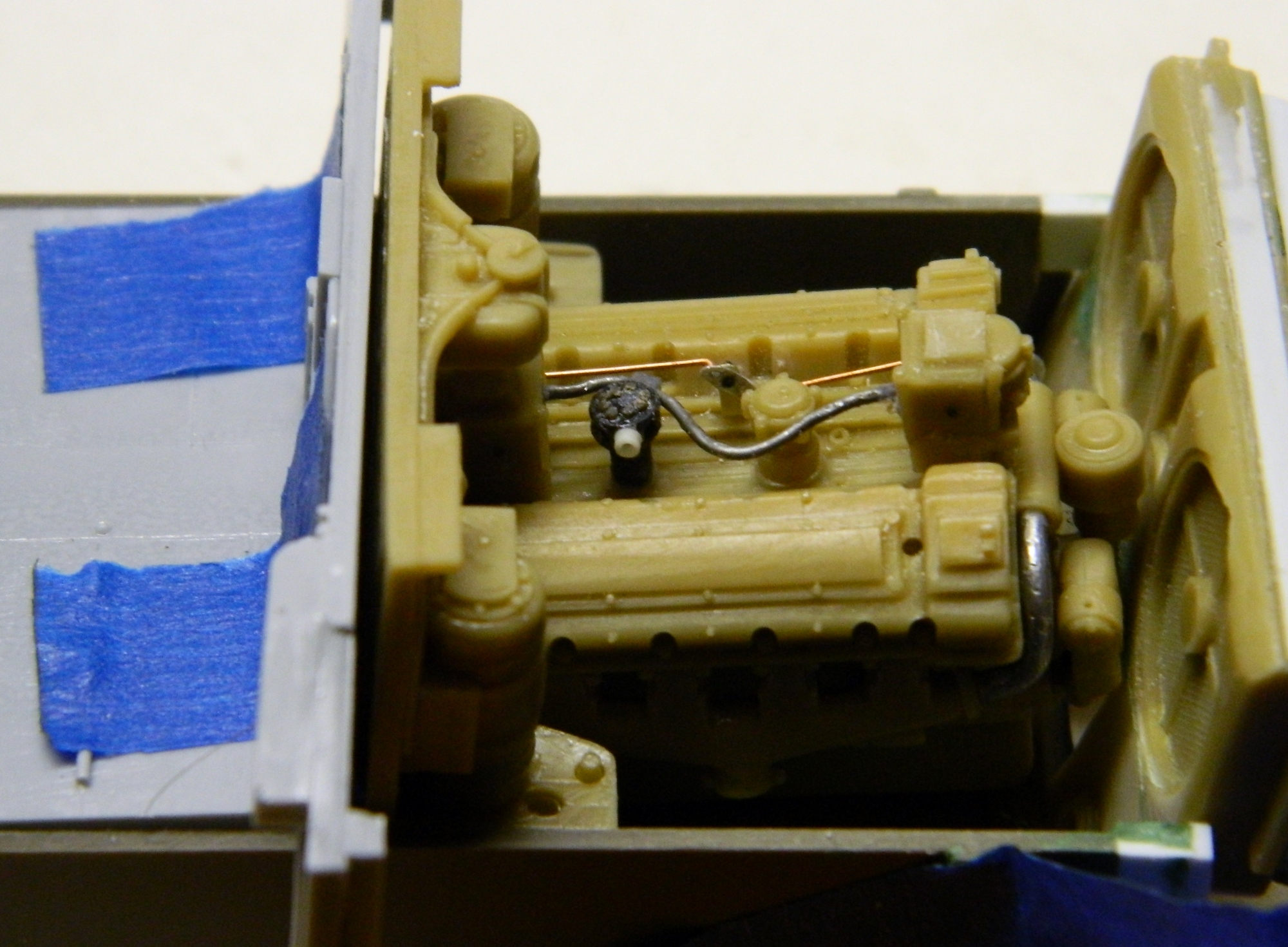
Still not enough. There needs to be a gap at the rear of the engine bay between the engine and the radiators that isn’t there:
I sat there for a while just looking at it and then I realized I was about one bulkhead shy of having the space I needed. On a Sherman tank, there’s only one bulkhead between the engine bay and the crew compartment, but because I was mating two AM detail sets into one hull, I had two bulkheads. Well, okay then…which bulkhead do I get rid of?
Yeah, well, not so easily done. Each bulkhead has detail that I’m going to have to put back if I toss one. So there was more sitting there for a while and just looking at it when the other synapse closed. If I take half away from each bulkhead, I’ll end up with the thickness of one bulkhead gone, which is what I need.
And then I was reminded of what I already knew but wasn’t thinking of. Resin only looks solid. It’s not, very. In fact, it’s quite flexible. As I was running the engine bulkhead across the file, I realized that the thick sections (which was where I had enough to grip) were being removed faster because the thin sections weren’t being pushed down with the same pressure.
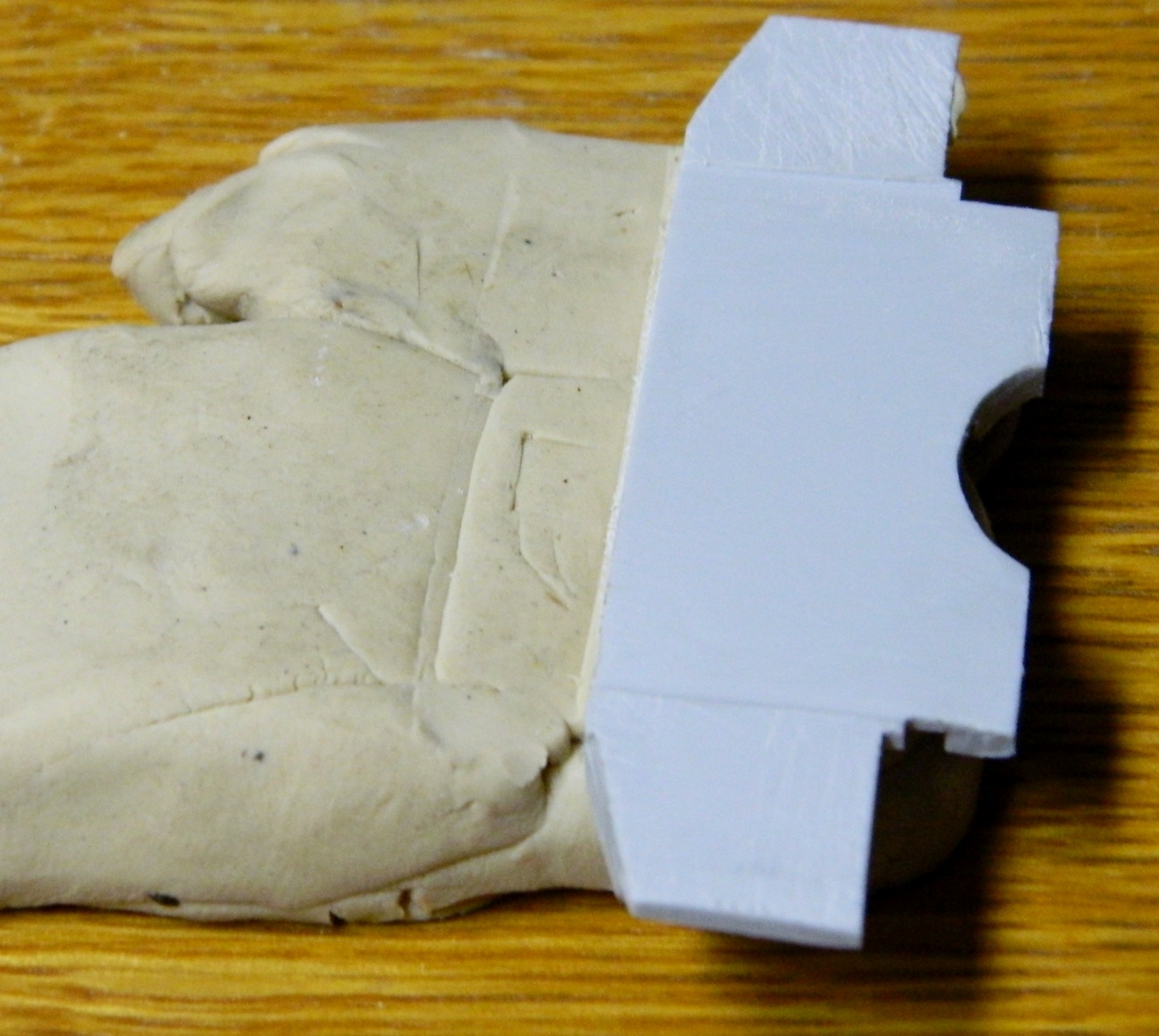
So there was more sitting there for a while and just looking at it when the other synapse closed that hasn’t operated since Nixon was President (first term). What I needed to do was to figure out some way I could support a very irregular surface evenly. Well. As it turns out, I have enough plastilene to (literally) choke a horse (though why a horse would eat a block of plastilene escapes my understanding). I bedded the face of the bulkhead down into the plastilene which in turn supported it evenly…and I filed away half the bulkhead:

For the forward bulkhead, I didn’t need to file the entire surface, just where the engine bulkhead came in contact:
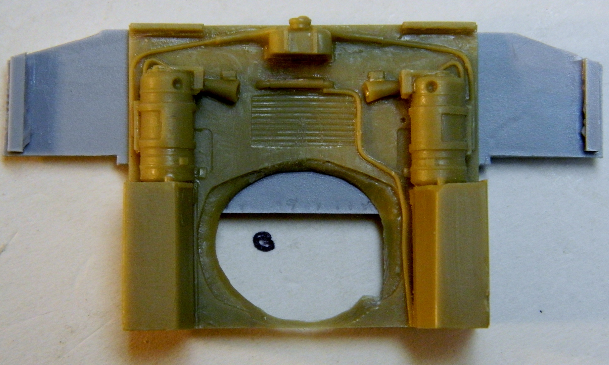
And that worked like a charm:

With the fitting problem solved, it was time to move on to the next fitting problem, getting the engine into the bay. Step one was to attach the rear engine mounts:

The plenum is connected to the air filter housing by hoses. Dry-fitting showed them to be too short. So I added styrene tubing to the ends of them:

This is how fragile resin is. I slipped once with the razor saw and a glancing blow did this:
So I added putty and set it aside to cure. Once it had, I put back the texture that was lost:

Next I needed to file the bottom of the engine mounts so that they would sit flat on the floor of the bay because they surely do not now:

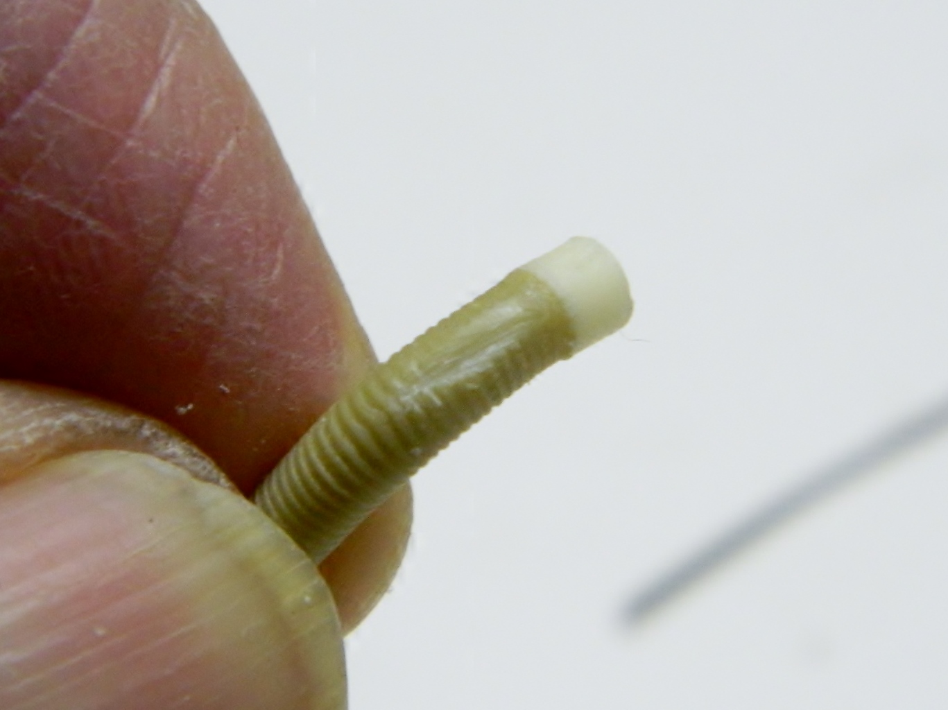
Once that was attended to, there are more engine details to add. Next up are the cooling manifolds that sit on top of the engine to each side of the carburetors, are evident, and although tubing came with the detail set to replicate them, they were nowhere near sufficient. These are made from .038″ (.965mm) styrene rod:
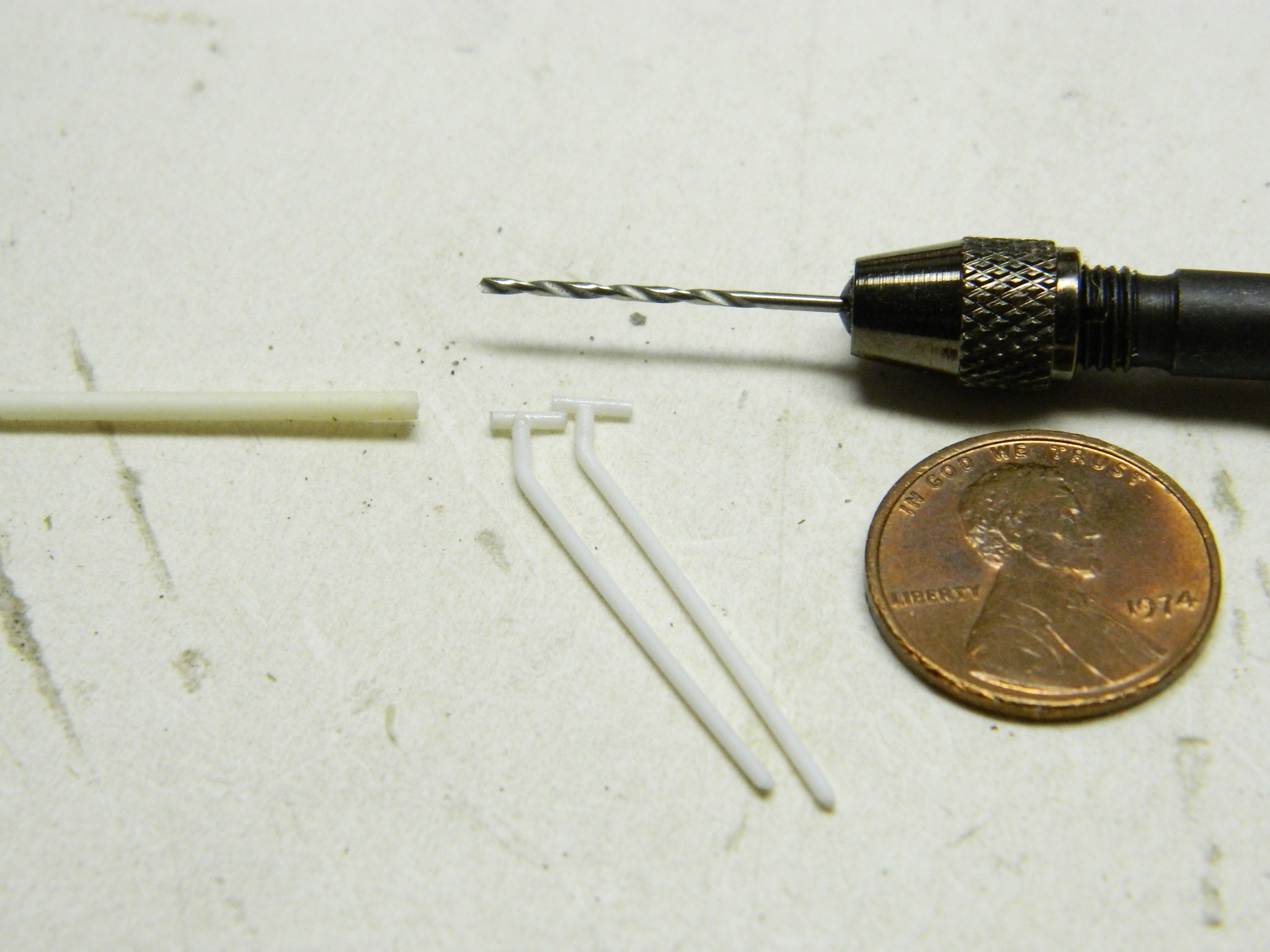
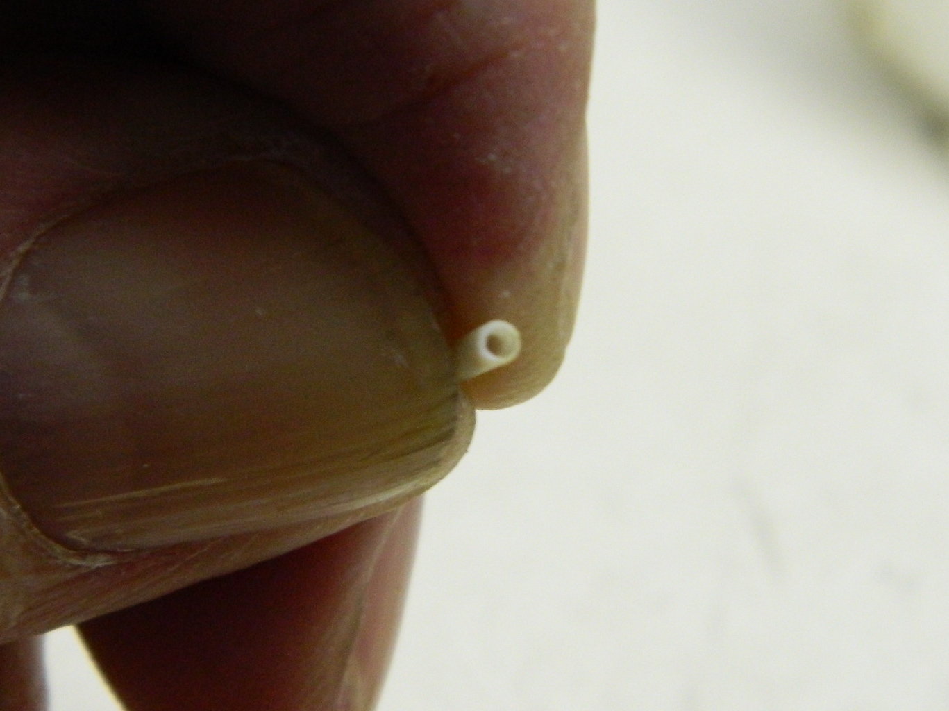
Things would be much easier if that’s all they needed but such is not the case. The front end of the manifolds are of a larger diameter and there’s a taper that joins the two. I took .068″ (1.727mm) styrene rod, drilled out the center to make a sleeve, tapered one end of it, and slid it over the .038″ (.965mm) sections:
After checking reference photos again, I decided that the taper of the cooling manifold needed to be longer more gradual, so I added putty and set them aside to clean up later: