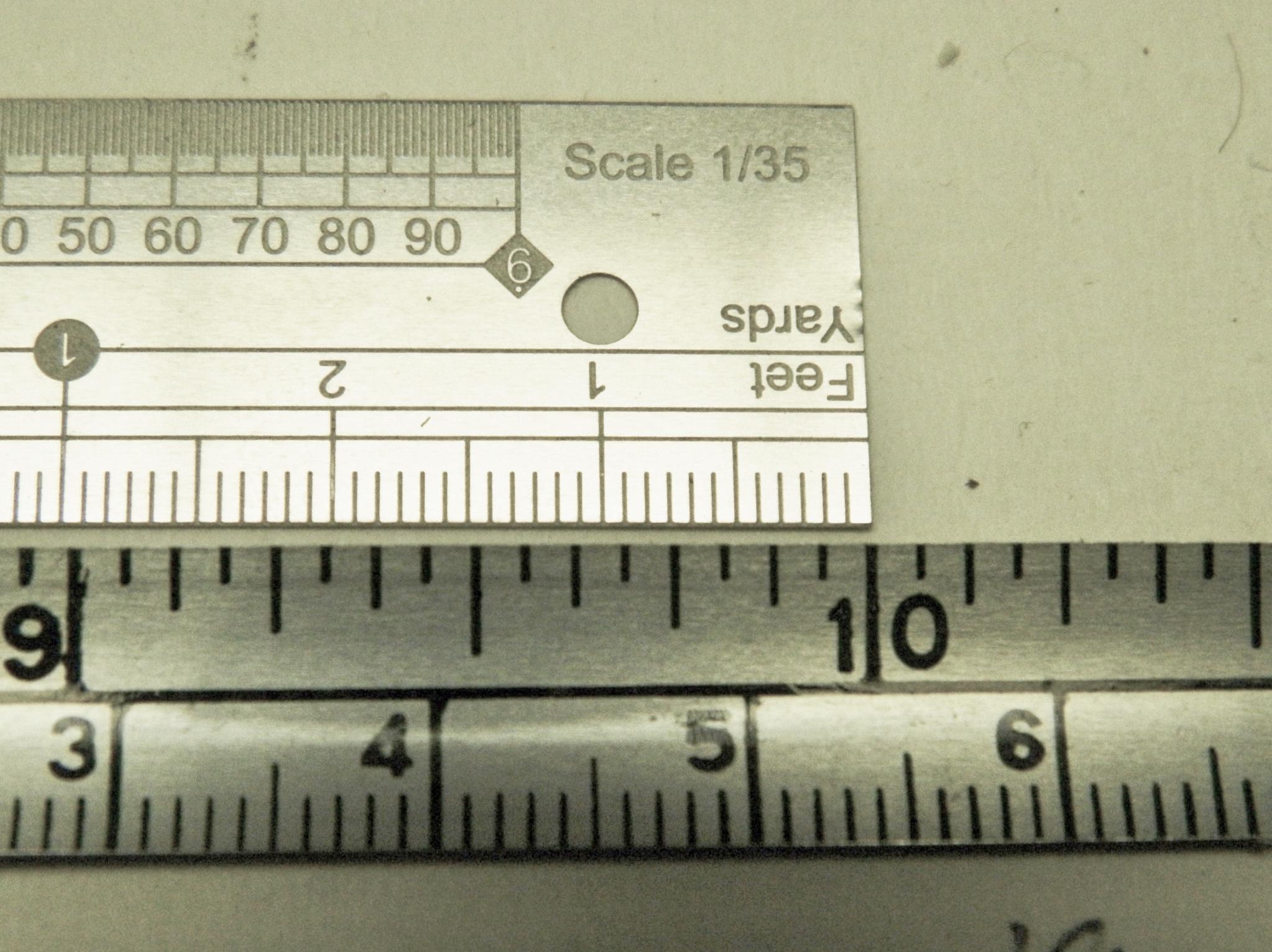
Now it’s time to finally address that outer radiator bulkhead and fix that. The drawings from my reference book are in 1/48 scale; ¼” (6.38mm) equals 12” (304.8mm). And as it so happens, I just happened to have a 1/35 scale ruler. This is the difference in a scale foot:
So how do I, a math-phobic talking monkey, convert accurately? CUE THE PROPORTIONAL DIVIDERS:
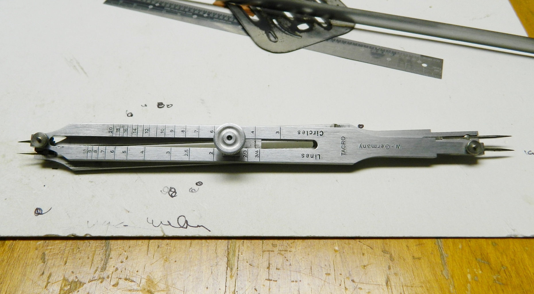
This is such a handy tool! The pivot will loosen and move. By positioning the pivot correctly, these dividers can transfer and convert a given dimension from one scale to another accurately. It starts by aligning the long tips to the larger scale and keep dicking with the position of the pivot until the small tips match the reference, which in this case is a foot:


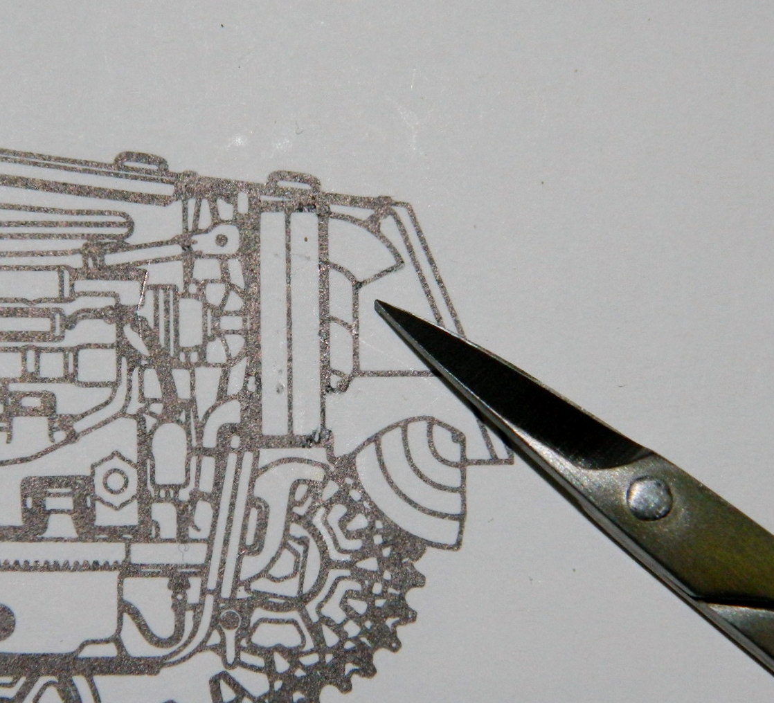
Now I can take a measurement from a 1/48 scale drawing and reproduce that length in 1/35 scale. The scissors are pointing to the piece I need to replicate, the ducting that’s mounted on the rear of the radiator bulkhead:
I decided to make a template using .010″ (.254mm) brass shim stock (because it’s sturdier), then cut the template out, trace it onto sheet styrene, then cut that out:

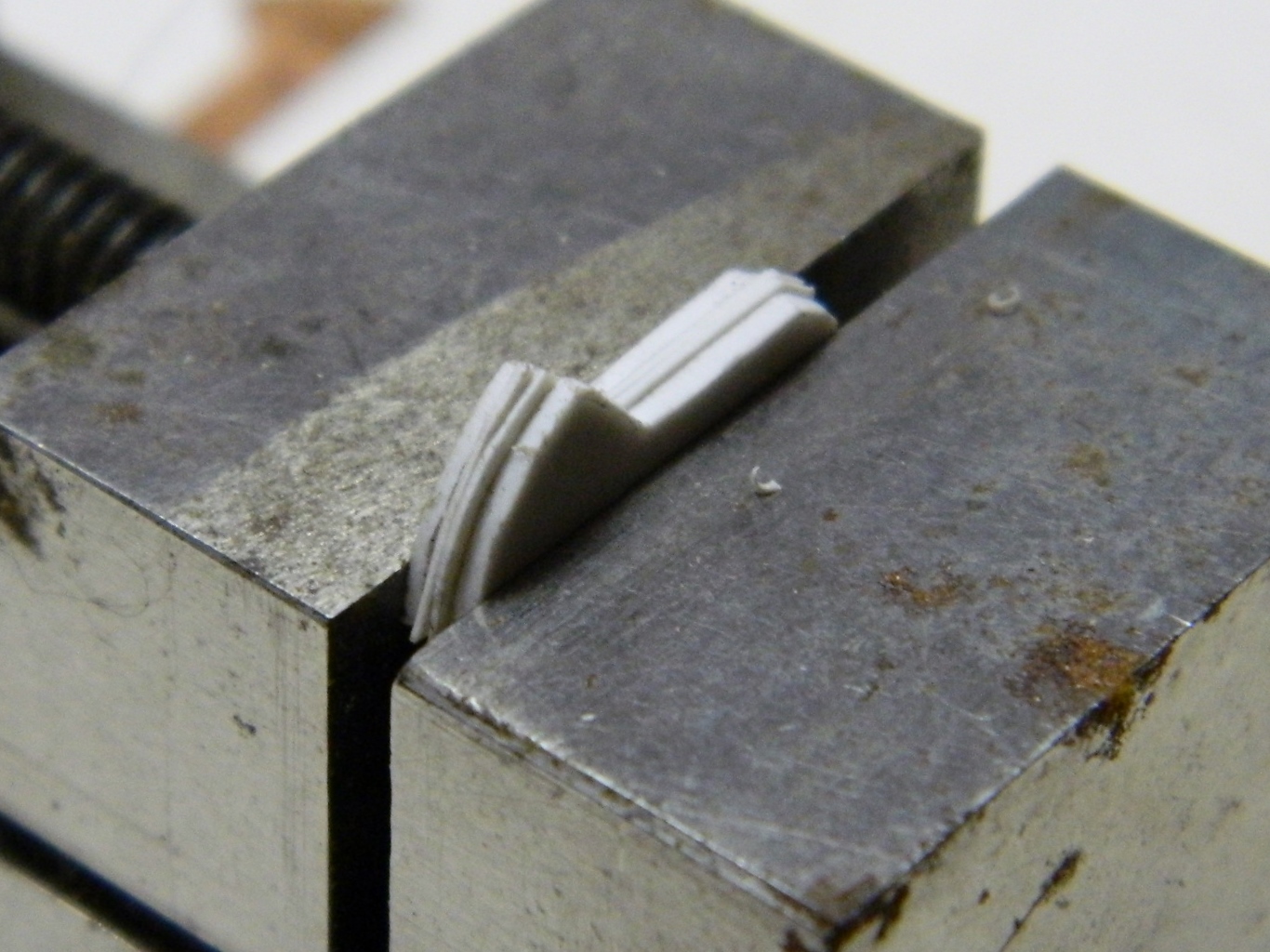
I need four vertical partitions. The outer ends look like they’re about twice as thick as the inner ones so I used .020″ (.508mm) sheet plastic for the ends and .010″ (.254mm) for the inners. I aligned them and then clamped them into a vise so that they would all be shaped the same:
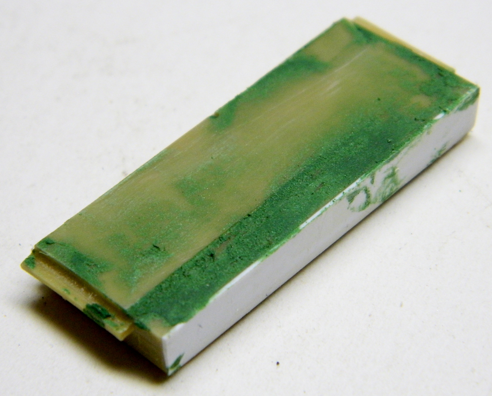
With the vertical partitions formed, it’s time to address the radiator bulkhead. I laid down a coat of modeling putty so that the final shaping would result in a flat surface without having to take too much material off to get there. If you think you’re going to need to add putty to a resin part, check before you commit to that course of action; not all resins will bond with all putties:
The lateral partitions of the ducting are curved so I need to create an even curve in plastic. I’d briefly considered doing the curved sections out of brass stock but I think plastic doesn’t solder well to that so I decided plastic would be better. How do I curve plastic evenly? CUE THE VACUUM MOLDER (you’ll find more information about that in “Side Projects” under “Vacuum Molder”). As it turned out, a half-inch (12.7mm) dowel offered just the curve radius I needed:

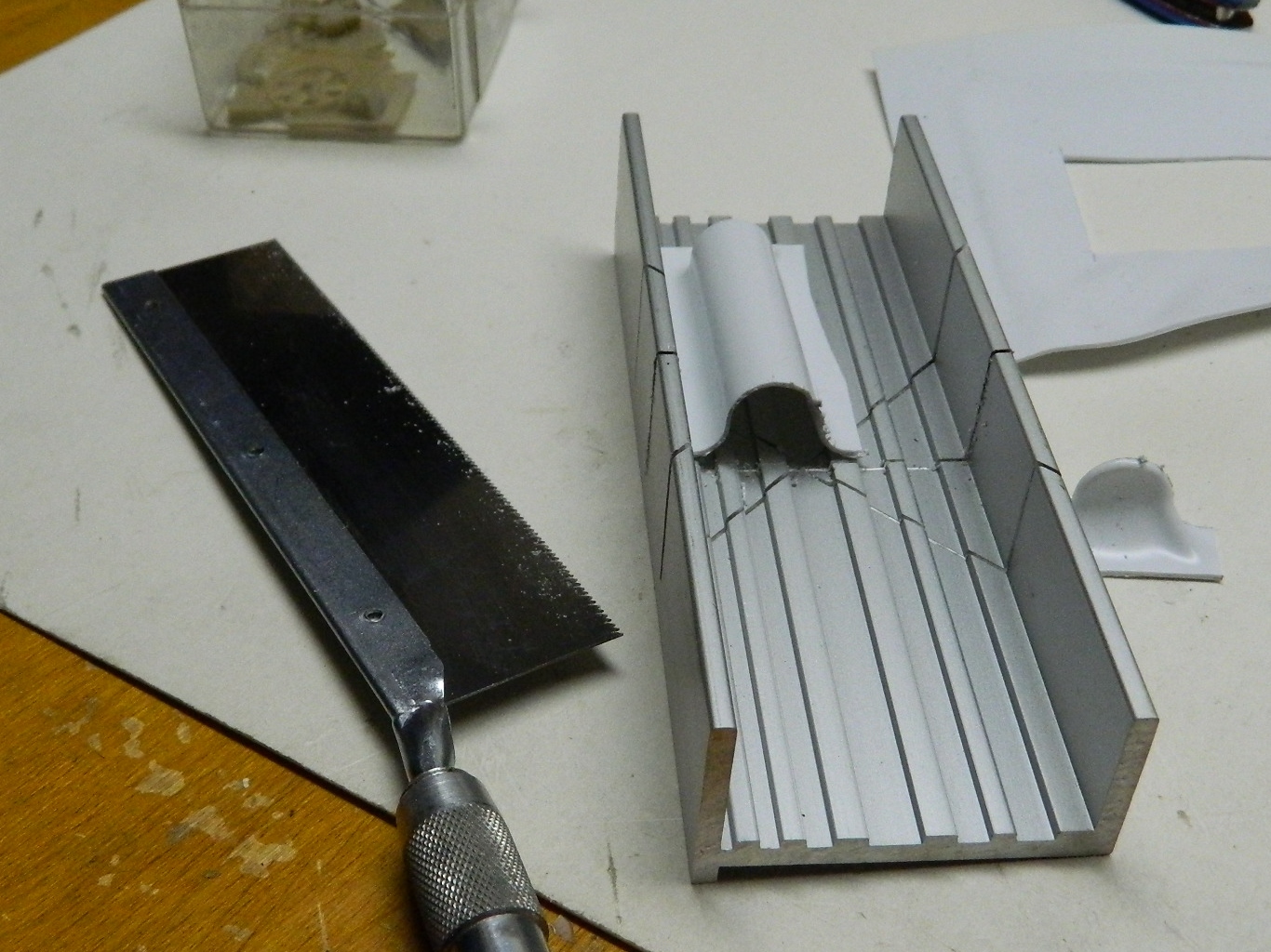
Then I pried the wood out of the plastic, trimmed roughly around the edges, trued up one side, and used my small miter box and razor saw to cut things to the approximate length (plus a little…the excess will get sanded off later):
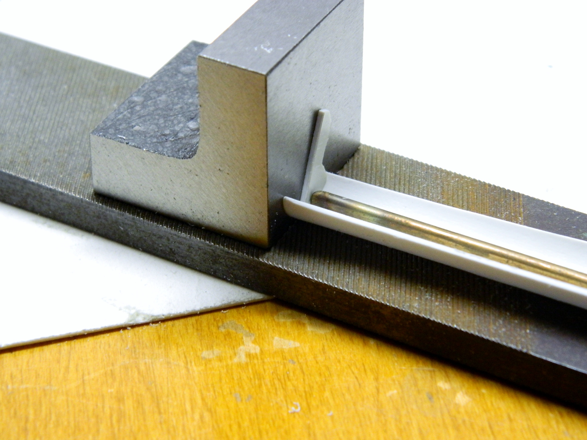
Next, I needed a more exact straight-sided piece. I knew that flatness would be relative to the sides of the ducting assembly, so I started by using a machinist’s square to align an end and glued it on (I used a file as my surface plane because I knew it was flat):
I’ve found it’s fairly easy to add things to an existing structure. Things get interesting when one has to build the structure to attach things to. Since I have one end glued on, I taped the pieces to the back of the radiator bulkhead and glued the other end on:

While that glue was setting up, I attached the bolt strip to the top of the differential housing. This part is one casting on a Sherman, that meant I had to fill in the small (but perceptible) gap between the strip and the housing. Somewhere I figured out that if I didn’t get putty INto things, I didn’t have to figure out how to get the putty out, so I masked off the area and applied the putty:

Now we let that cure…
