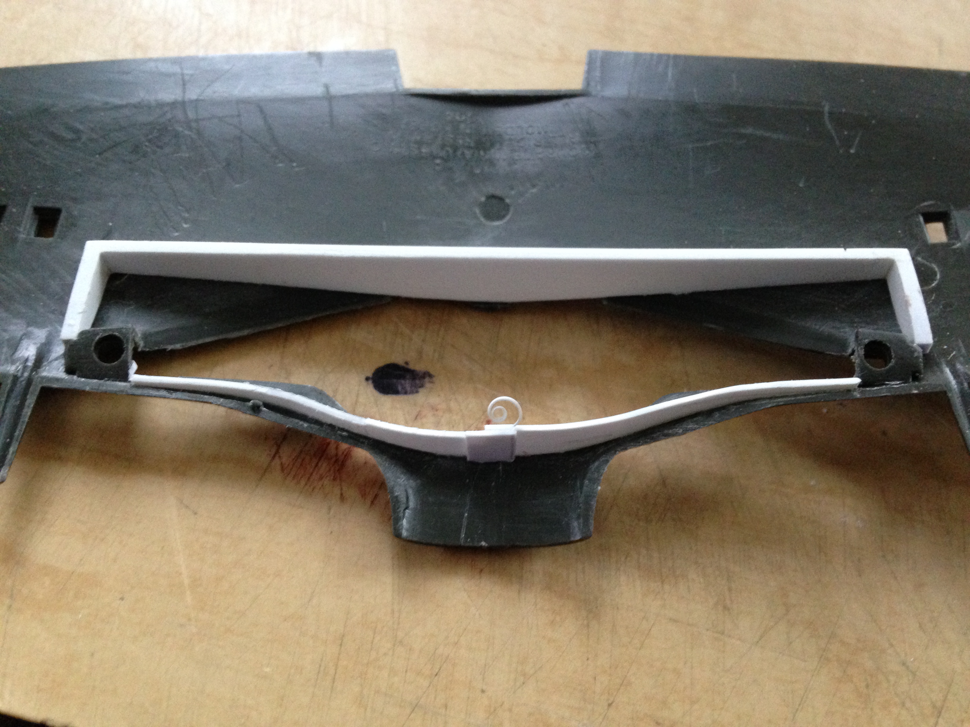
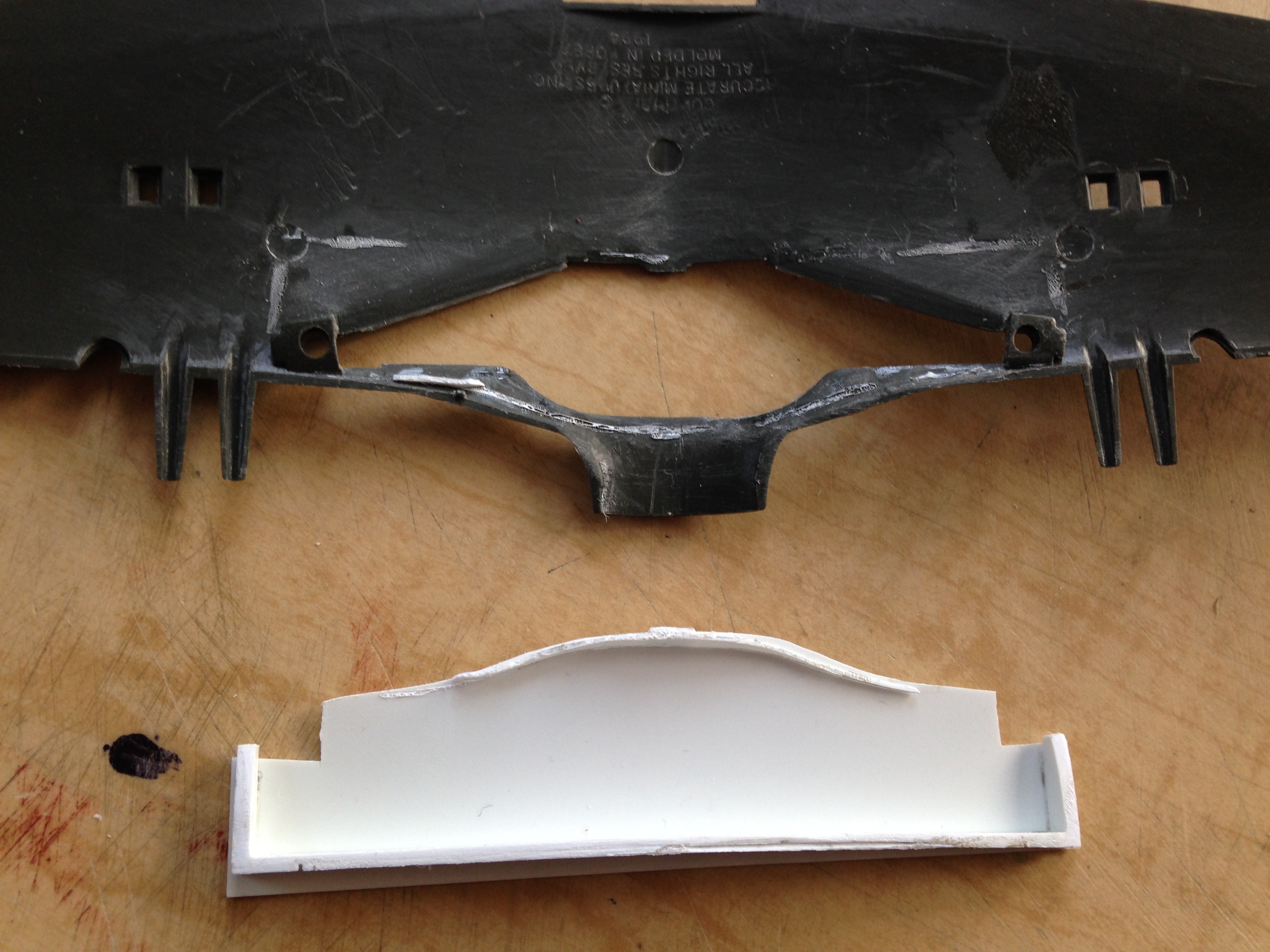
Since the delivery time from Roll Models was quite long, while I was waiting I figured I’d get after the landing gear wells. That started by sawing out the molded box and start getting what will replicate the main wing spar dimensioned and built. Since I wanted to keep the one accurate detail of the molded-in wells as my dimensional reference, I ended up cutting each well away separately (probably complicating the job).
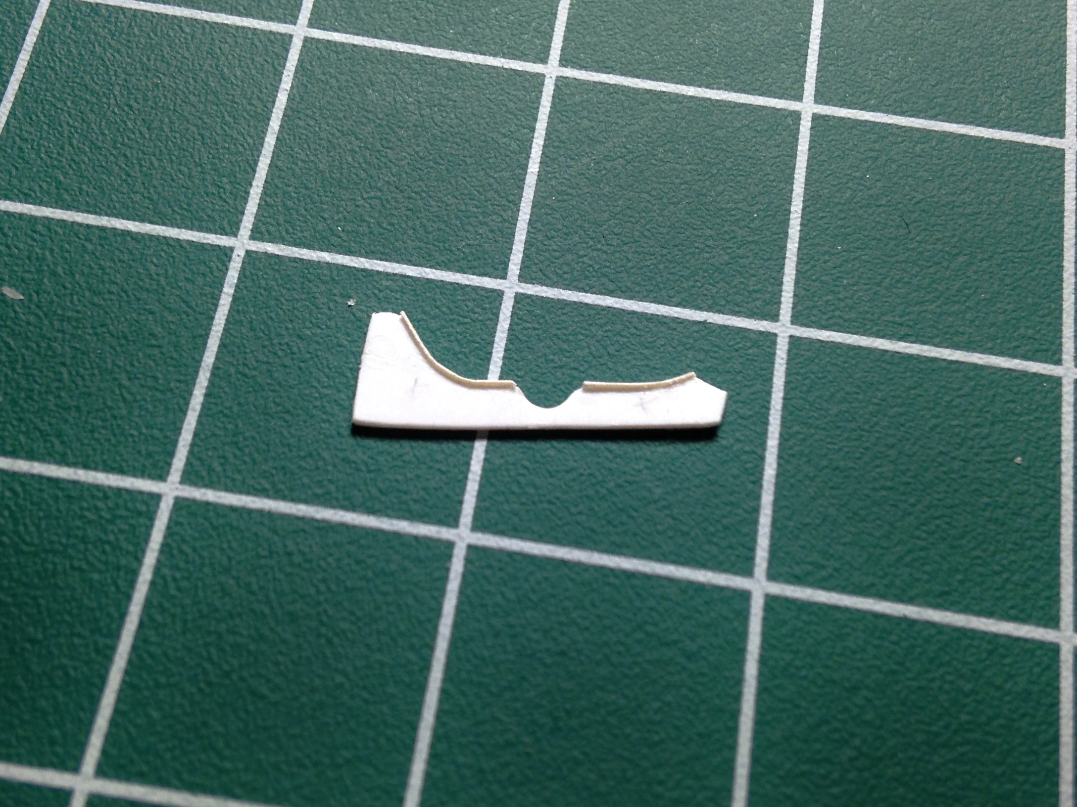
I used the one correct section of the molded-in landing gear wells as my reference. Once I had access to that section, I used card stock to create a relative template (so-called because I’m going to have to fit this fabrication inside the wing and I’ll do that once I have it in plastic as that’s more rigid and easier to work) and then transferred that shape to plastic and taped it in place:

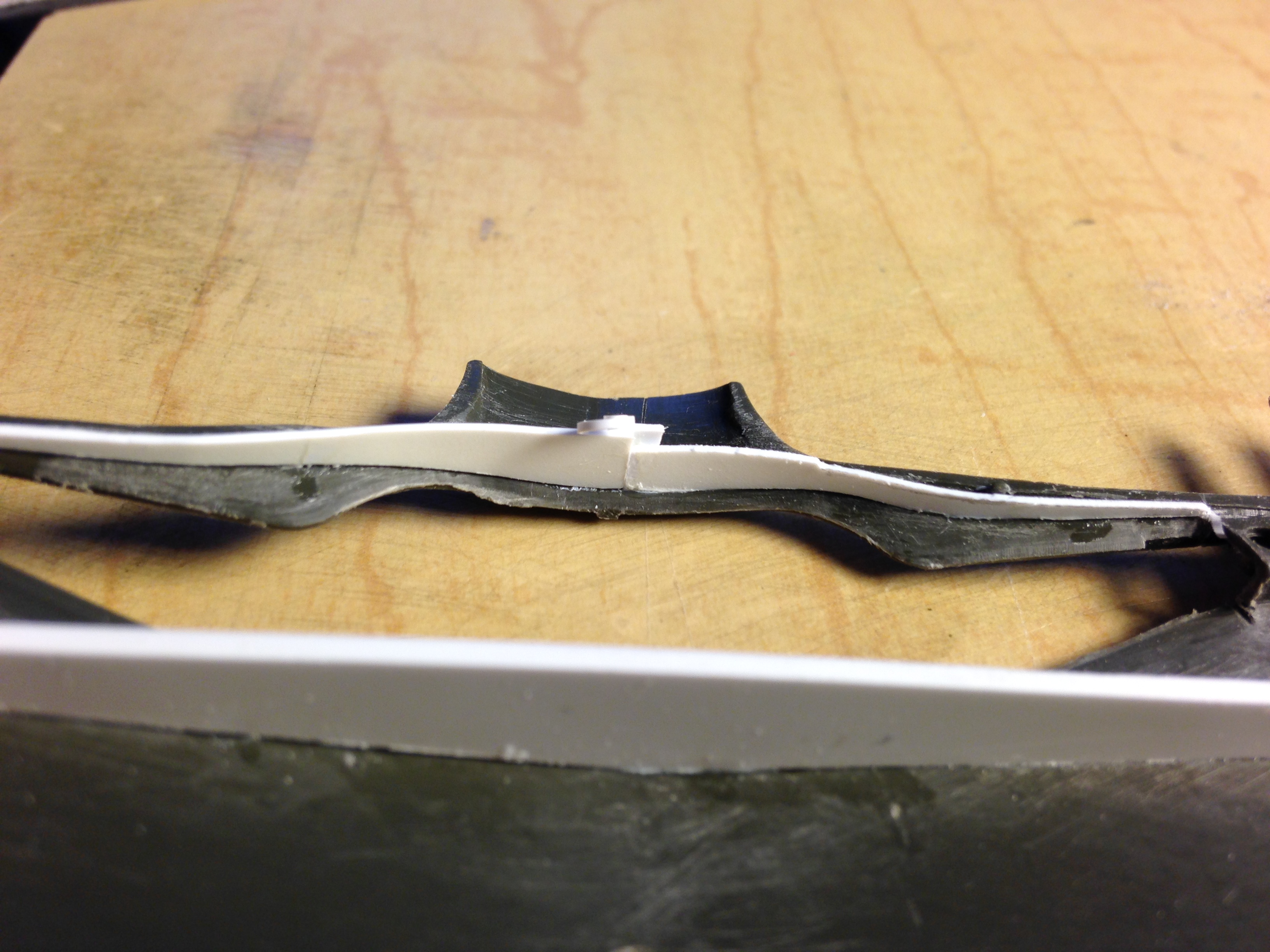
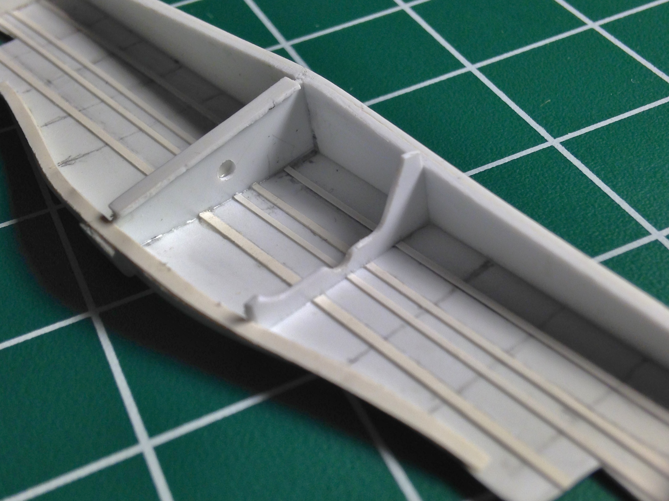
With the plastic cut, I checked it for fit using the rib as the terminus:

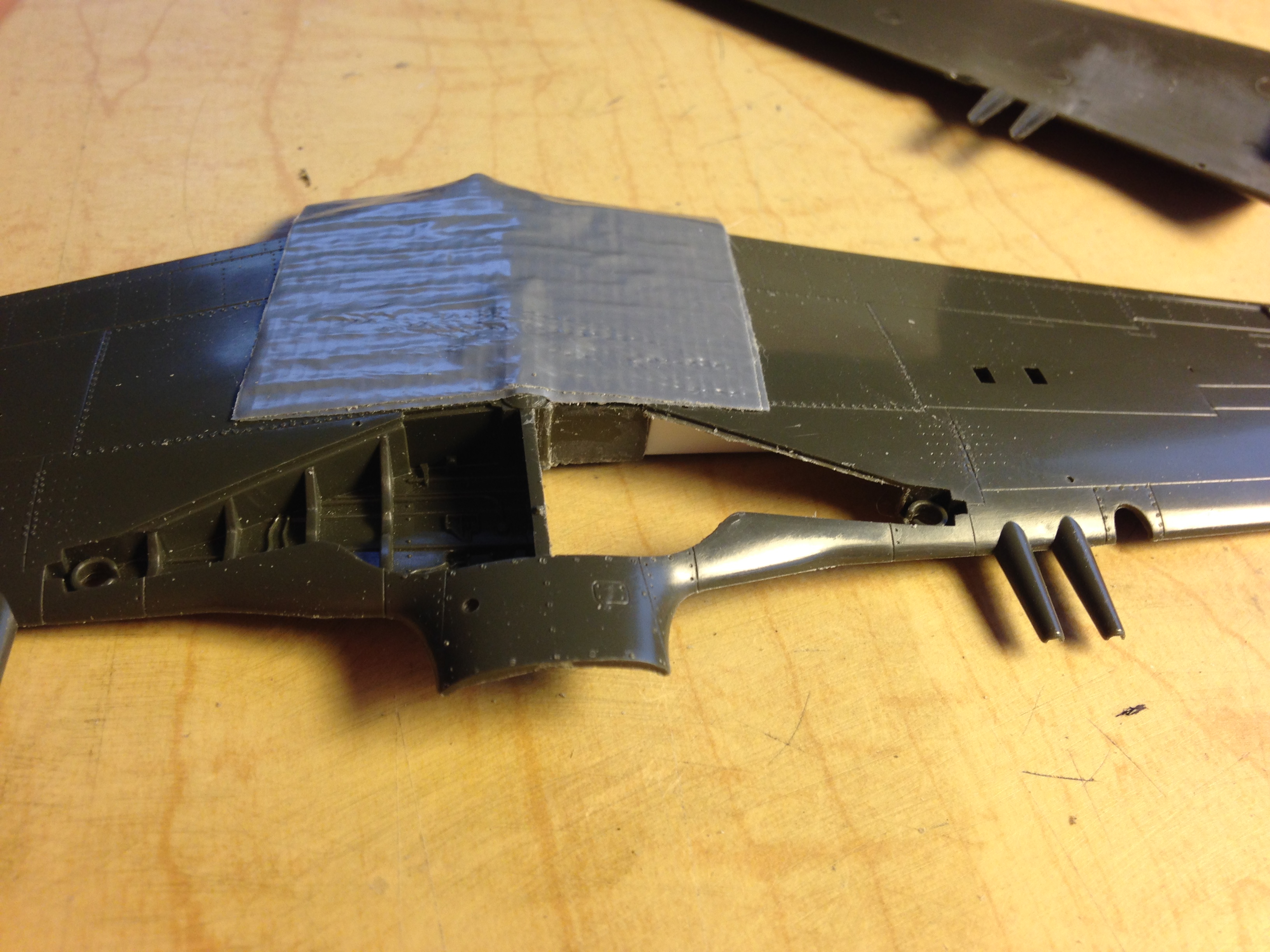
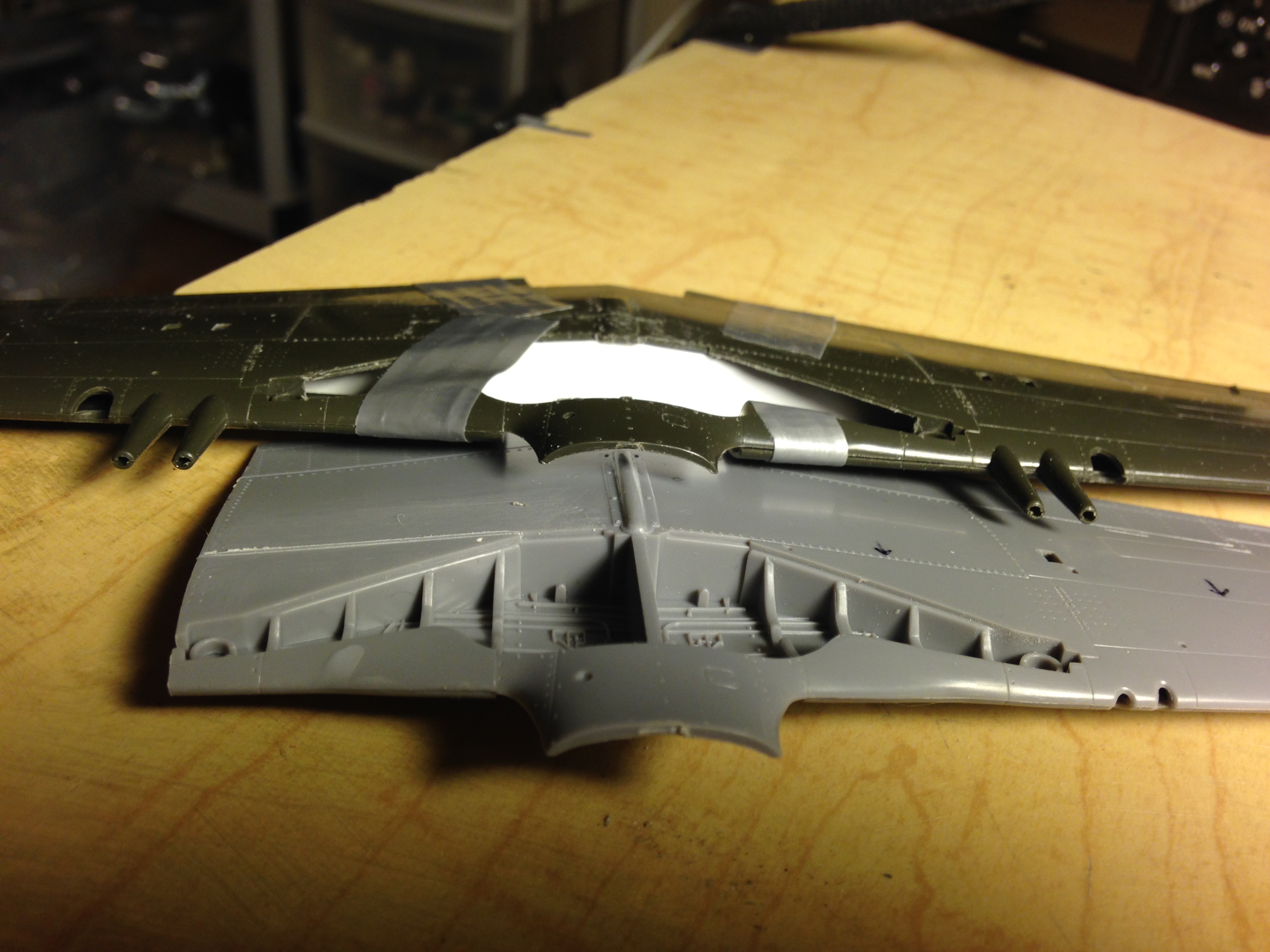
I started by using duct tape (upon which modern civilization is built) as my guide and used a panel-scribe to start laying out where I need to cut:


I neglected to take photos of the first removal but the coffee finally kicked in, neurotransmitters started conducting a current, and I remembered to take photos of the second removal which shows how I did the first removal. I started with many passes using a panel scribe and once I had broken through the plastic, used the small #11 saw to finish the job (note the proximity of the knurled collar of the knife to the belly of the wings, which I didn’t notice during the first cutting…and that oversight created more work for me, as I’ll show you shortly):


I left the molded-on landing gear attachment on both sides for structural strength when it comes time to add the landing gear legs:


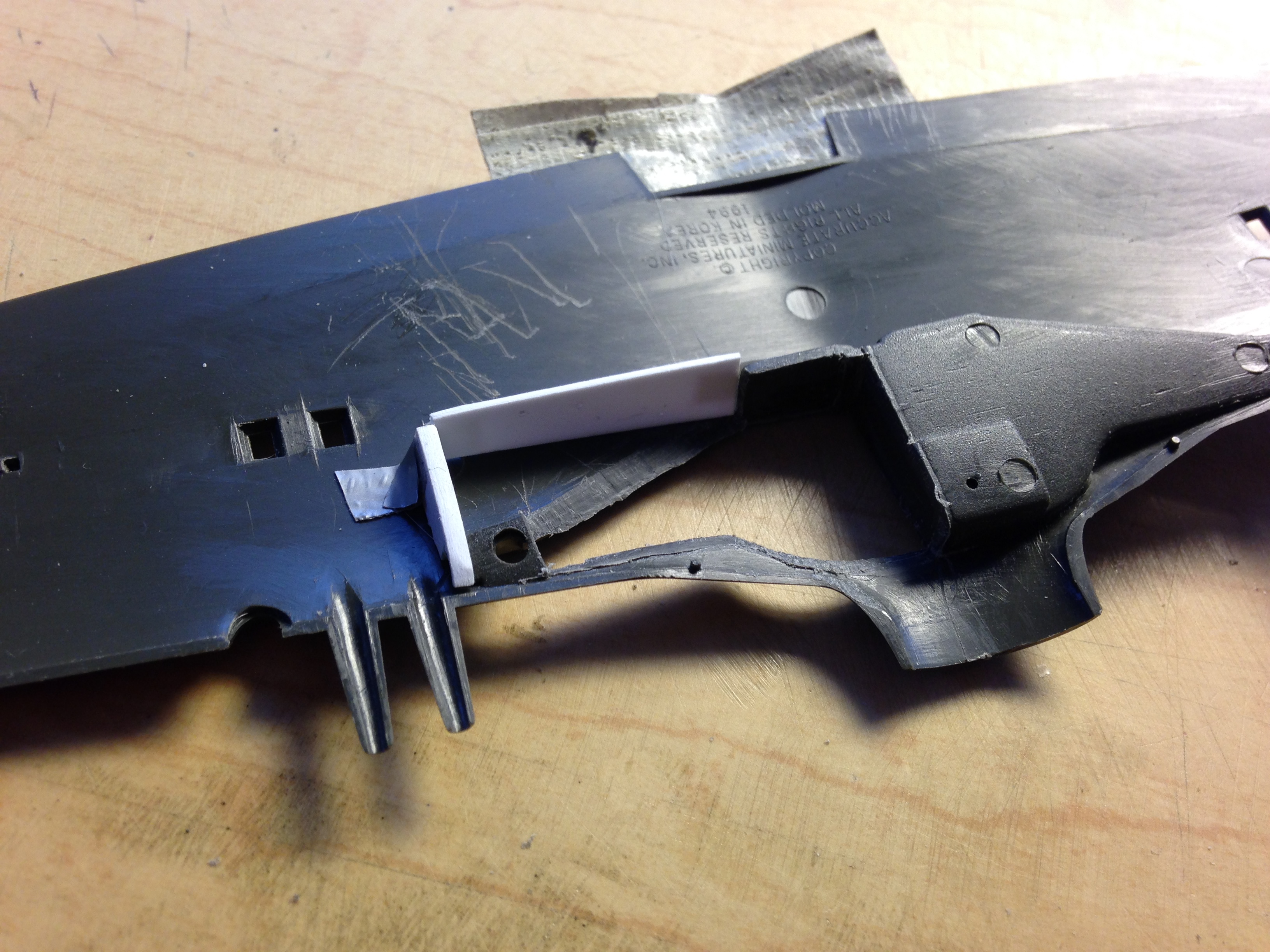
Once I had cut away both of the molded-in wells, I had access to the width of the gear wells and made a template for the main wing spar and transferred that to .020″ (.508mm) sheet styrene:

That got taped into position and much sanding ensued to fit it:
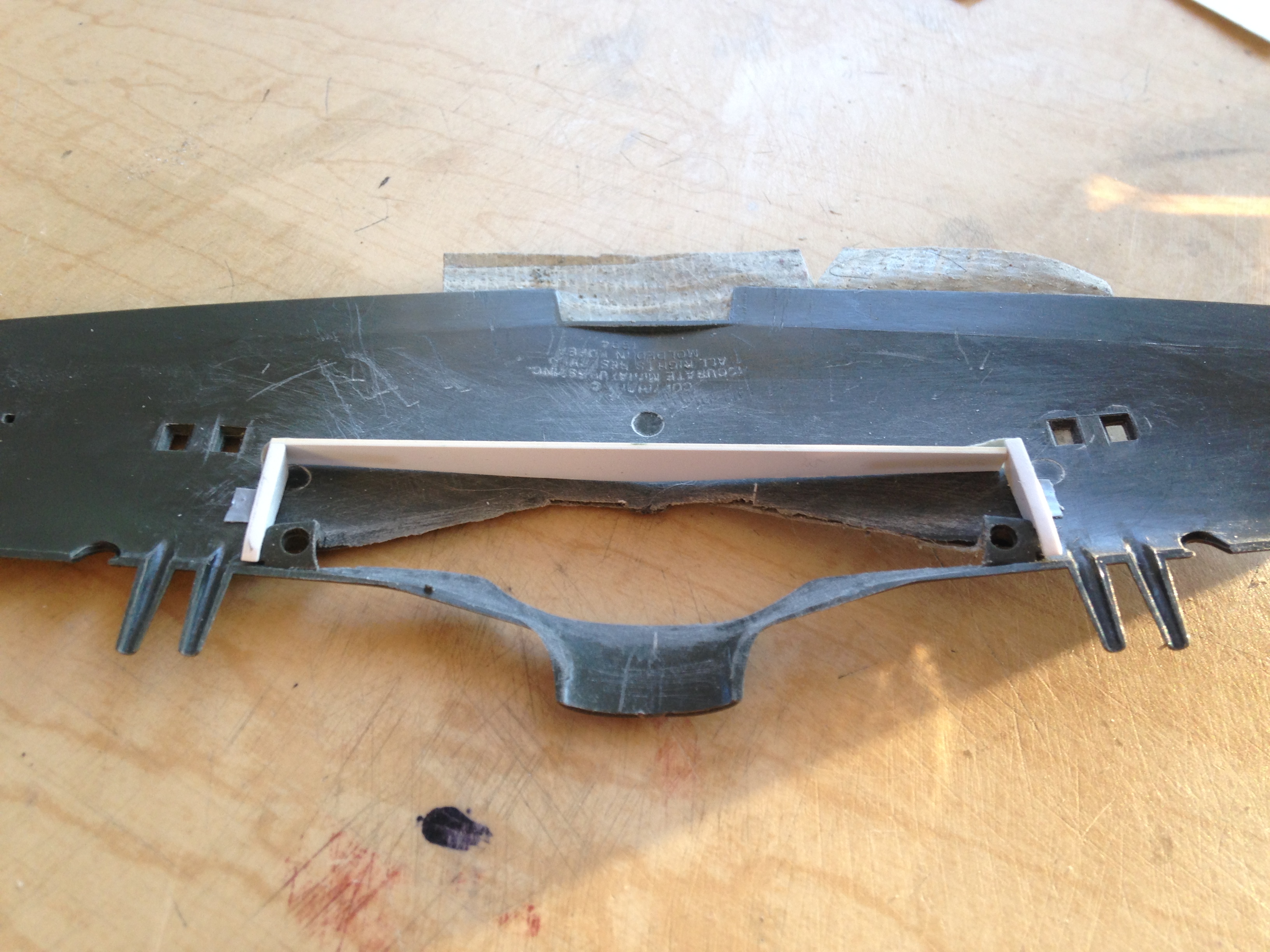
With the spar laid out, it was time to fit it into the wings, which started by shaving down the lip on the inside surface of the upper wing sections that have to encapsulate the spar:
With the main spar (mostly) fabricated, I checked fit. Yeah…that’s what it’s supposed to look like:
I used the molded ribs as templates for the ribs I’ll fabricate to replace them. The kit’s ribs were sawed free of the boxed landing gear well and the rough (very rough, as it turned out) shape of the ribs was transferred to card stock to create rough (same caveat as above) templates:


Since I plan on molding and casting this assembly, I added another layer of plastic sheet to the wing spar for ease of pouring later on, and then I started fitting the front of the well. At this point dry-fitting was getting into the realm where even having four hands would have been challenging so I tacked the spar/ribs in place with glue and started adding the front of the wells:
Once I had things about where I wanted them, I added a sheet of .020″ (.508mm) to close the top of the box and then pried the “tacked on” sections off (it was…challenging), only breaking a small piece off the front area which I glued back into place:

I added more sheet to the front of the wells, also to facilitate pouring resin later on:

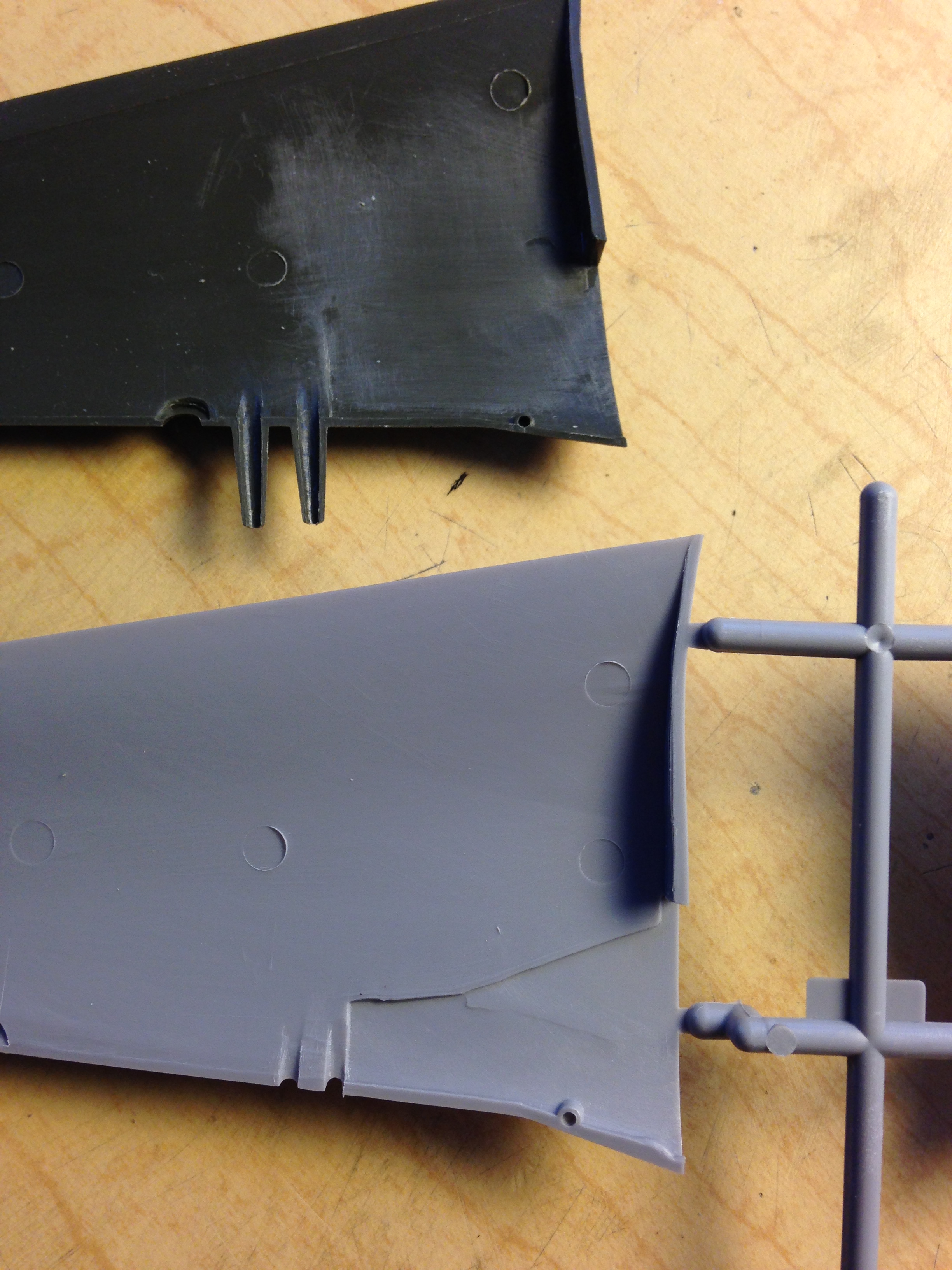
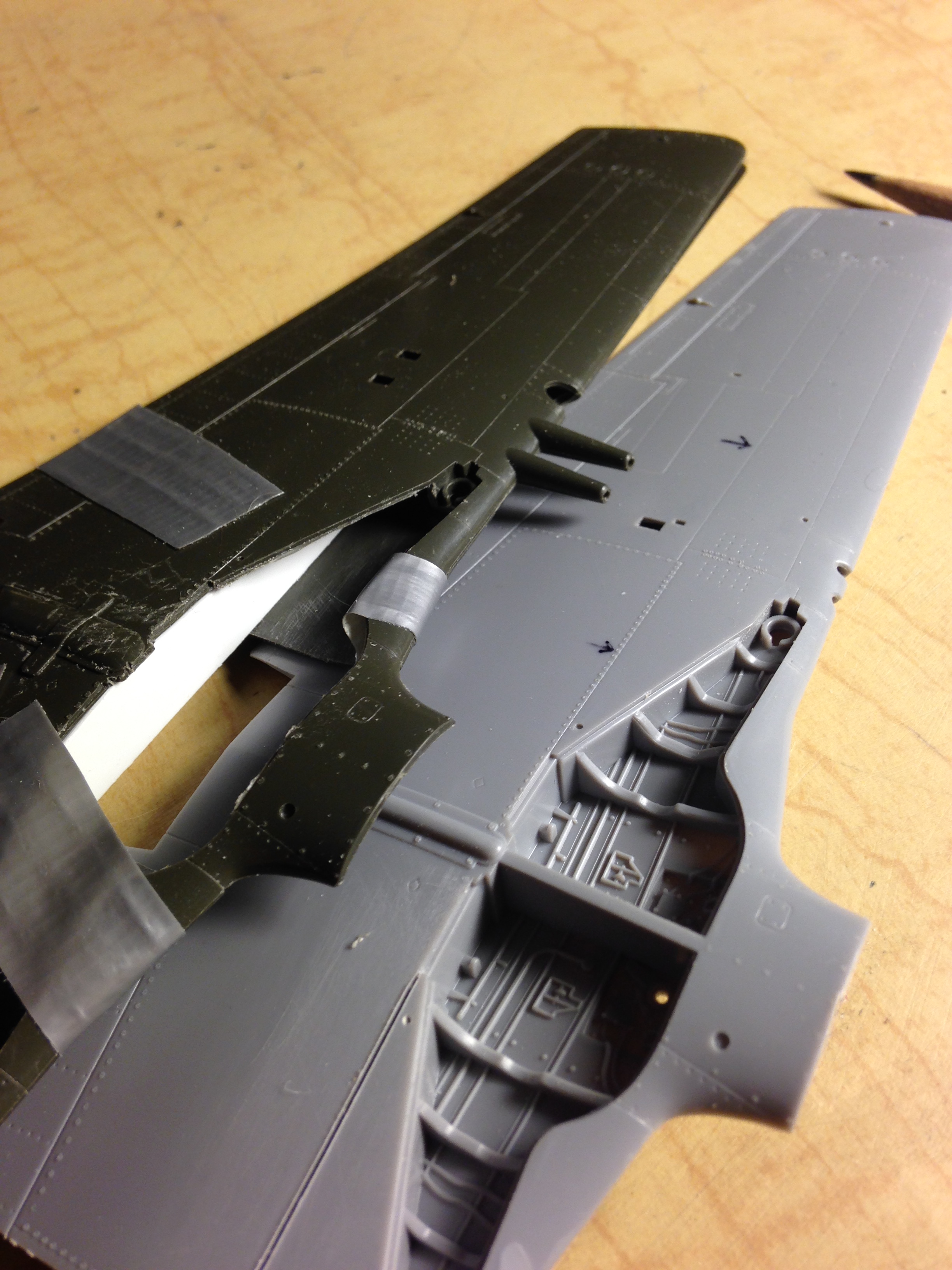
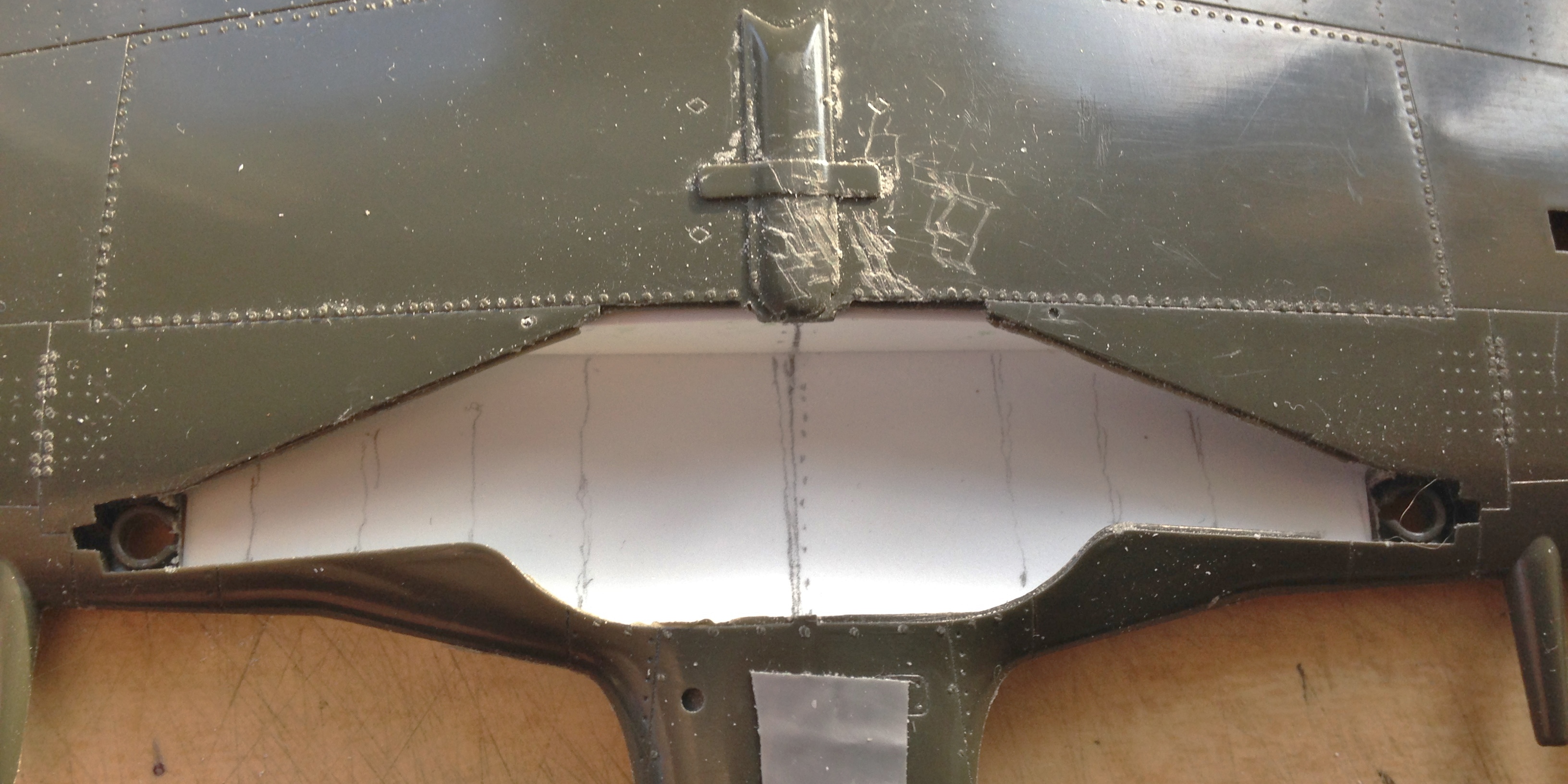
I placed the landing gear wells onto the wing to lay out where the ribs need to go.
You’ll note how chewed up the underside center of the wing is. This is what can happen when one (me, particularly) focuses on one area being worked without paying attention to adjacent areas that could be (and in this case was) affected by the tool. That area got chewed up because I was so focused on the area I was sawing away that I failed to notice that the knurled handle of the Exacto knife saw was rubbing on the wing. So that’s going to need fixing:
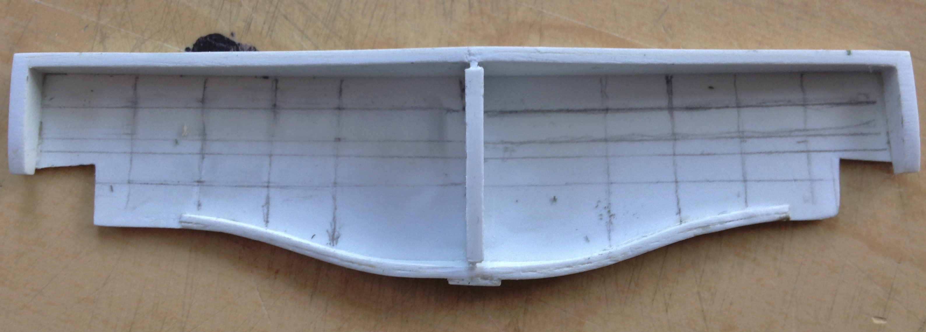
An easy way to transfer measurements from one side to the other is by using a compass. I used the pivot point to follow the center line to get the spacing correct (or at least consistent) for the ribs:


From what I can tell, each wing of the Mustang was built separately and then bolted together at the center, leaving a partition between the two wings. I added that:
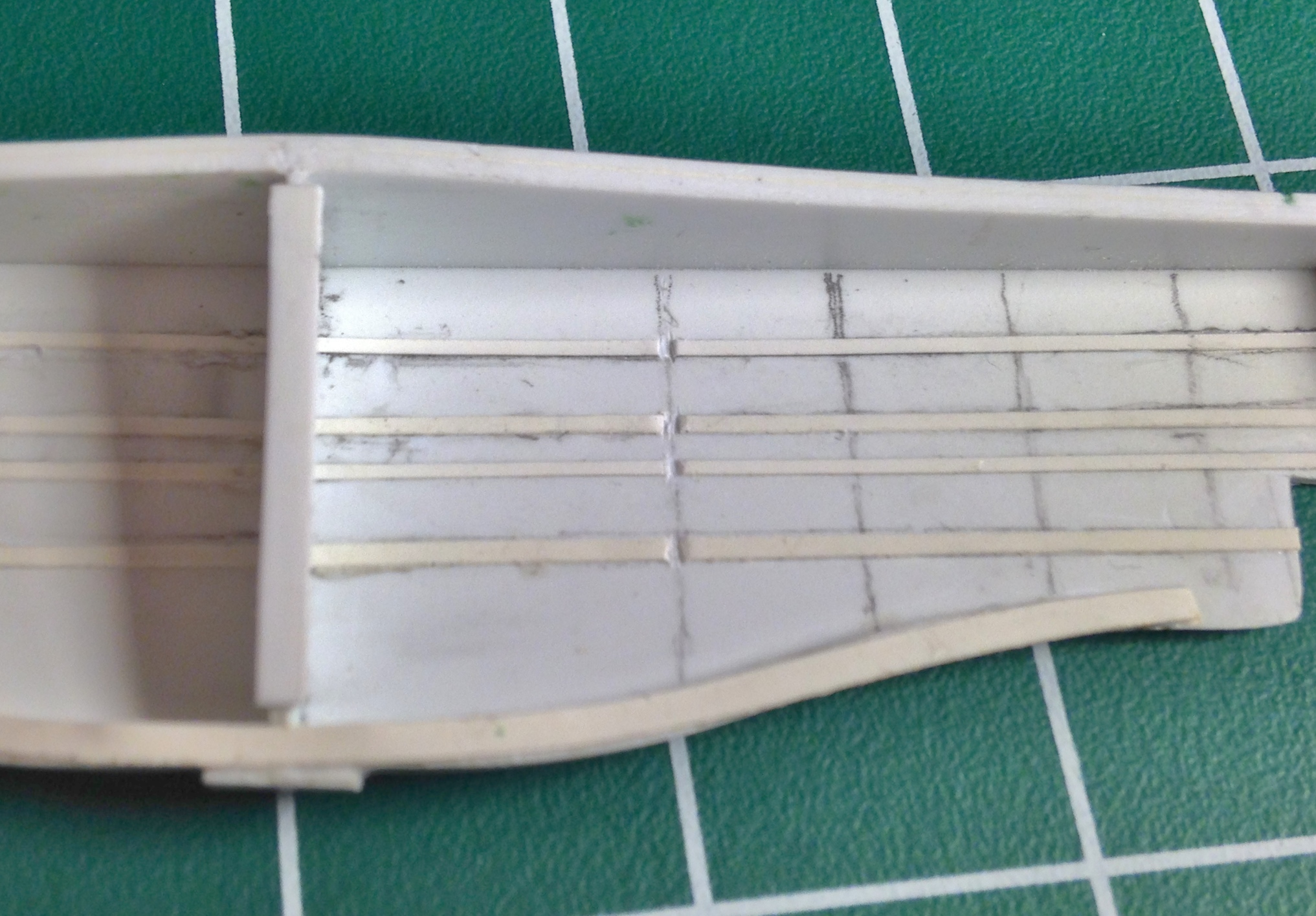
I used 005 styrene strip for the stringers:

The center partition has a prominent hole in it so I drilled one. However, when I make a mold of this assembly, that hole will keep the part (and the master, too) trapped in the silicone. An easy fix was a “plate” covering the hole of .005″ (.127mm), something easy to sand off once this is replicated in resin:


I debated notching the ribs to fit over the stringers and then realized it’s a LOT less work to notch the stringers:
I cut the ribs out of .015″ (.381mm) (still too thick, scale-wise, but more realistic in terms of getting that space to fill with resin later) and checked how it works…which it does:
The stringers on the Mustang have ridges and I replicated them using lead wool:

With the rib form finalized, I used .005″ (.127mm) to add the lip (after sticking the rib to double-sided tape for ease of working). Once the glue had cured, I sanded the lip down:

Then all the ribs had to be fit and that’s when I discovered how rough the templates were. There were many mistakes made during the fitting of the ribs including holes drilled in incorrect locations (and sizes) which had to be plugged and re-drilled, thin sections of the styrene breaking under handling which had to be reattached, but after much invective (both colorful and anatomically impossible), I finally had them finished (and hopefully correct):

They were then glued to a sheet of .040″ (1.016mm) styrene for ease of molding and casting:

The next step was to build (what I think are) the hydraulic cylinders that operate the landing gear (As an indication as to how small these things are, the squares of the cutting pad underneath it are half inch squares). Once I had those done, they got added to scrap styrene to create the pouring blocks for molding and casting:

Tiny details consume large blocks of time…
And speaking of consumption of time, I added the various details to the wells that I could. The hydraulic lines, wiring, and cables that run through this area can’t be added now because they’re free-standing from the surface. If I add them now they will be captured by the molding rubber, not that I think I could cast those sections in resin anyway because of their small diameter:


Simply amazing. The penny really helps to ground your work to a commonly understood object.
LikeLike
Thanks. Without visual references it’s easy to forget how sodding TINY these things are…which in a photograph means I’ve done my job technically well.
LikeLiked by 1 person