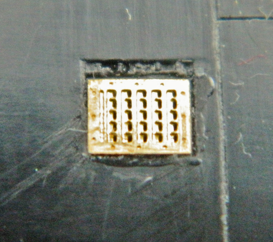
While waiting for the micro-lathe to arrive, and having no shortage of things to do, I attended to a couple of fuselage details that were annoying me. The PE details for various surface grates are very nice. Mistakenly, I took the two grates that most closely fit the molded on grates and installed them. The grates on the Blackbird are flush mounted (makes sense, considering drag slows an aircraft down and the Blackbird isn’t famous for going slow) which meant I had to align them, outline them, and then scrape away enough plastic to socket the grates flush:


One of the interesting things I noted while at the NASM was that the fuselage panels on the belly of this beast aren’t butt-fit (meaning that the edge of one panel meets the edge of the next) but overlapped like shingles. To replicate that, I laid some .005″ (.127mm) sheet down to create the lip of the trailing edge:

While I was waiting for the cement to cure, I noticed that there are two grates that go towards the front of this belly section. Then I noticed that I’d already used those grates…in the wrong place. The grates I just socketed into place don’t go there, other larger grates go there. ::sighs:: With heart in mouth (which I’ve discovered makes breathing a bit difficult), I slipped the edge of a chisel blade under the edge to pry them away from the superglue and out of the putty. Damned if that didn’t work just fine. Not having a clear photo of this area, I made the decision to place them where I did. The larger grates were held in place and I scribed around their edges with a needle:

Satisfied that maybe now I was on the right path, I repeated the scrape, glue, and putty cycle with the correct grates in the (relatively, I hope) correct location (after one false start, evidenced by the lines at the left of the left grate below):


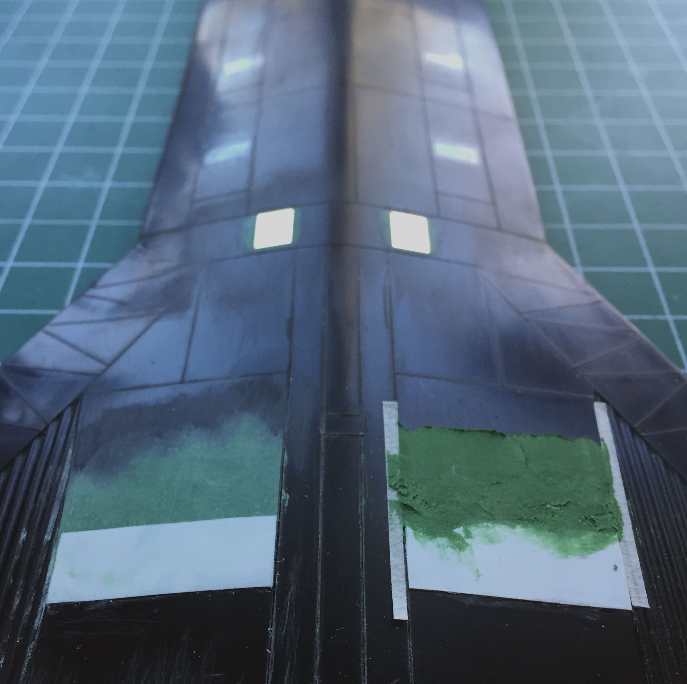
With that mistake recovered, the multiple thin layers of putty I laid down at the leading edge of the .005″ (.127mm) sheet had set up, allowing me to block-sand the putty flat:
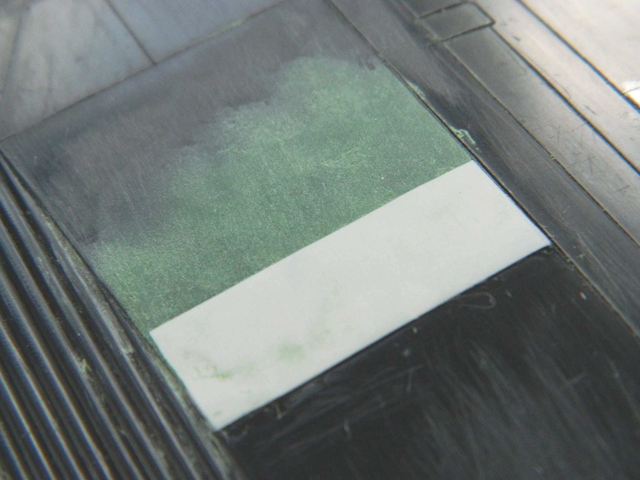
Satisfied with the outcome, I repeated the process on the other side, using thin strips of masking tape to keep the putty from getting into places I didn’t want it to get into:
Things occur to me when they do. With this blog, I can present things as if these things occur in a linear manner…but they don’t. The most recent example of this occurred the next morning, propped up in front of the bench, and when the coffee finally wet my neurotransmitters sufficiently for them to propagate a spark, I wondered, “Do I need to add nose weight for this thing to sit properly on its landing gear?” Rather than do useful work so soon after that initial daily spark, I taped all the major components together to see what the weight distribution looked like. I placed the supports directly under where the landing gear parts are going to mount:

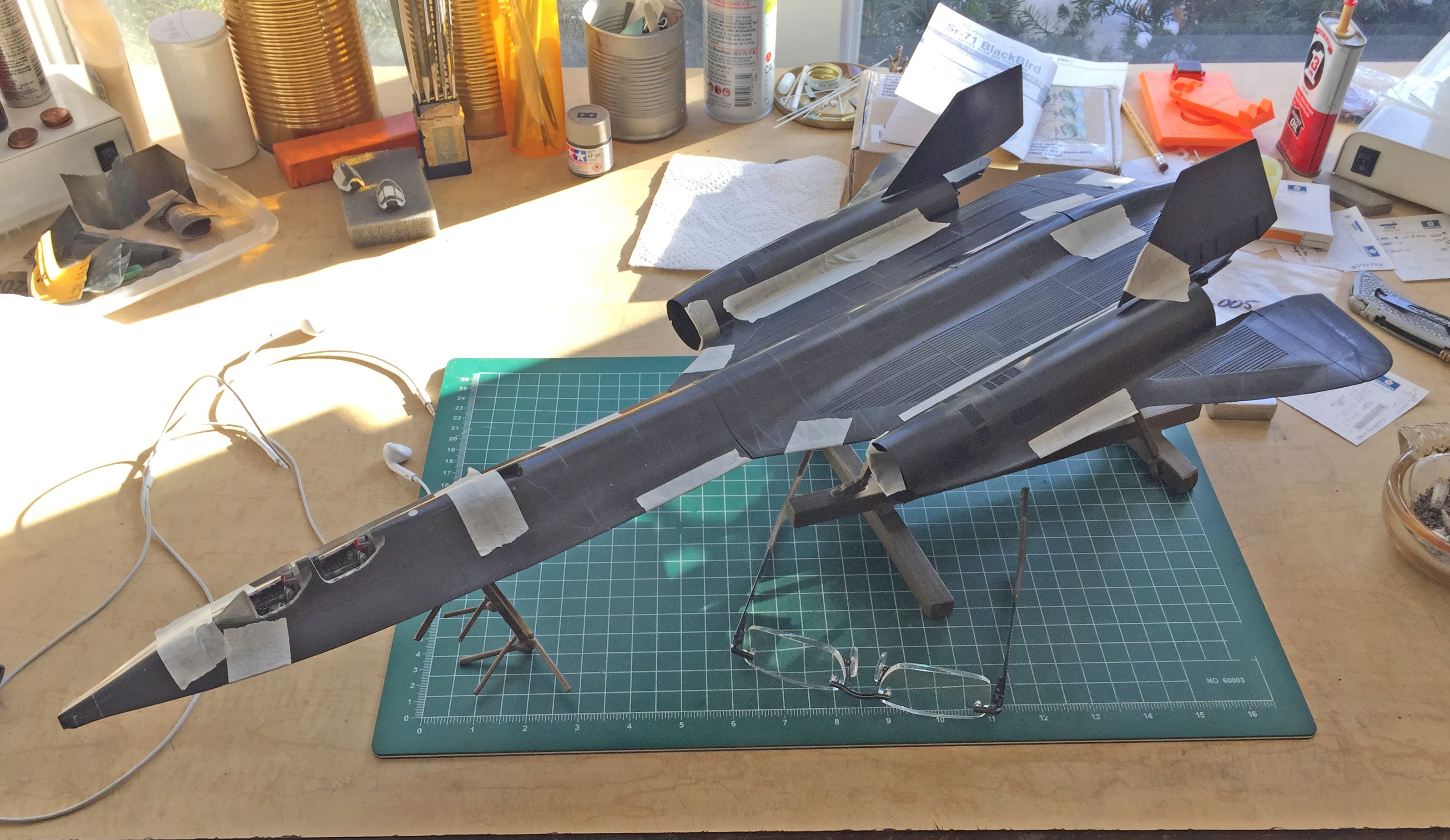
Two things became evident. 1) No, I’m not going to need to add weight. 2) this is going to be a big model.
And then my new micro-lathe arrived! I spent the rest of that day unpacking, cleaning, lubricating, and getting to meet my new tool. It’s not as accurate as an old Unimat. It also cost about half of an old Unimat. Since I am not a watchmaker (or work in 1/72 scale), I don’t need the degree of accuracy an old Unimat provides; this one will work well enough for my purposes.
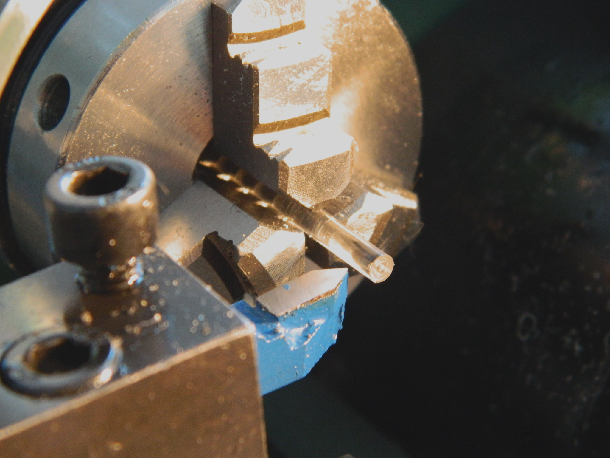
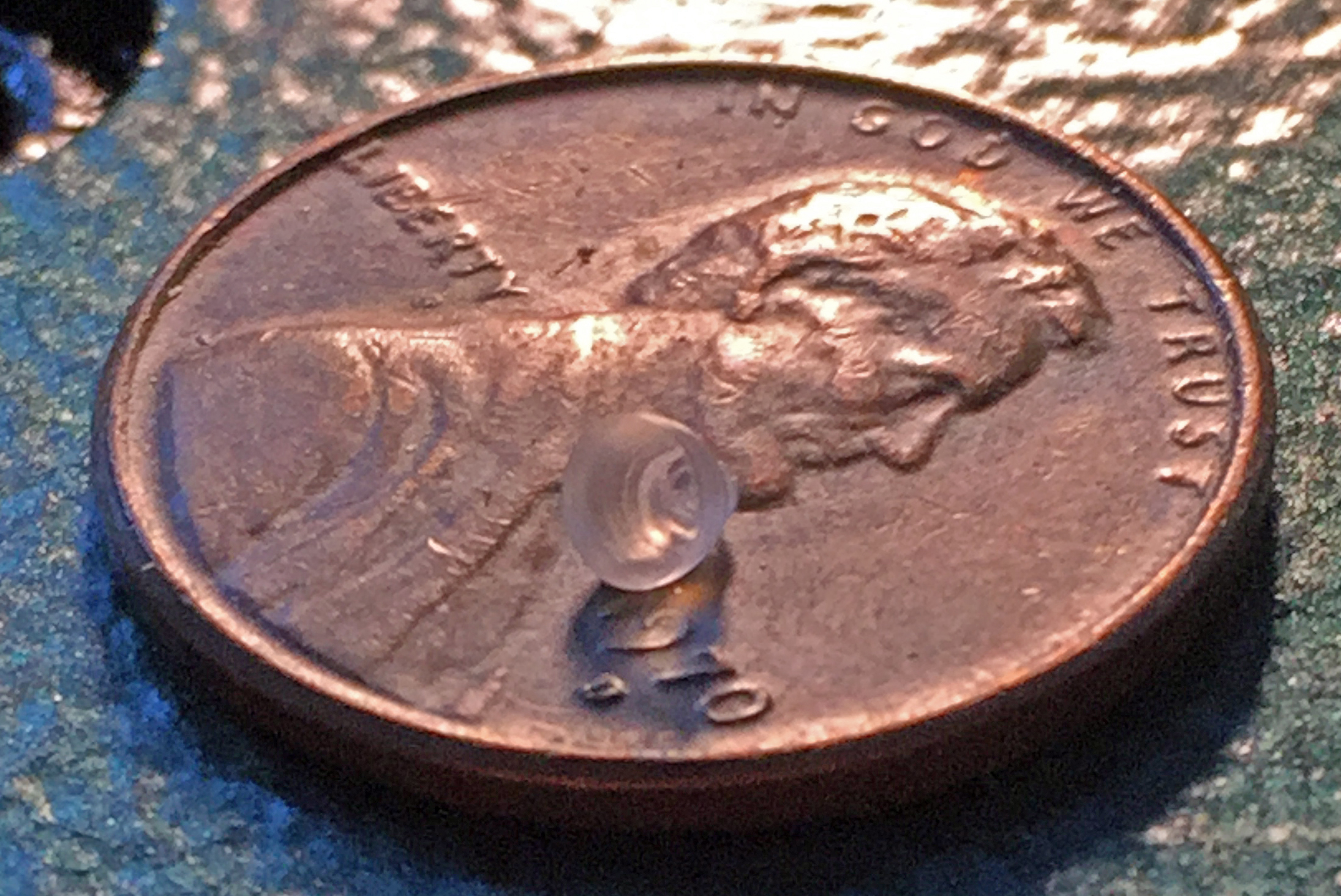
After getting comfortable with how the new lathe works, I turned the second landing light from a quarter-inch (6.35mm) clear acrylic rod:


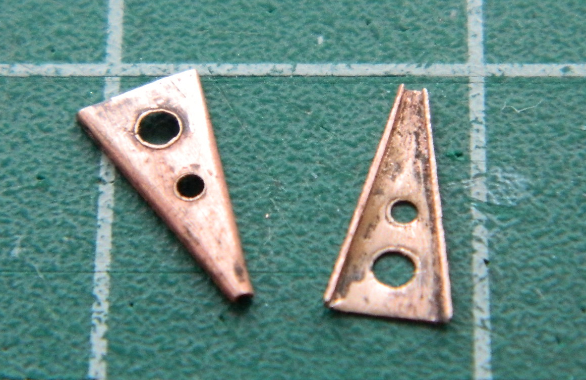
Landing gear on large aircraft is more like a very strong shock absorber and they’re called an “oleo”. They compress under load and extend when unloaded. Something has to be attached to keep the oleo from overextending and those extension limiters are triangular (generally). That’s the type used on this landing gear. I used .005″ (.127mm) copper shim stock to make them and that started by laying out their basic shape and punching two lightening holes in each part:
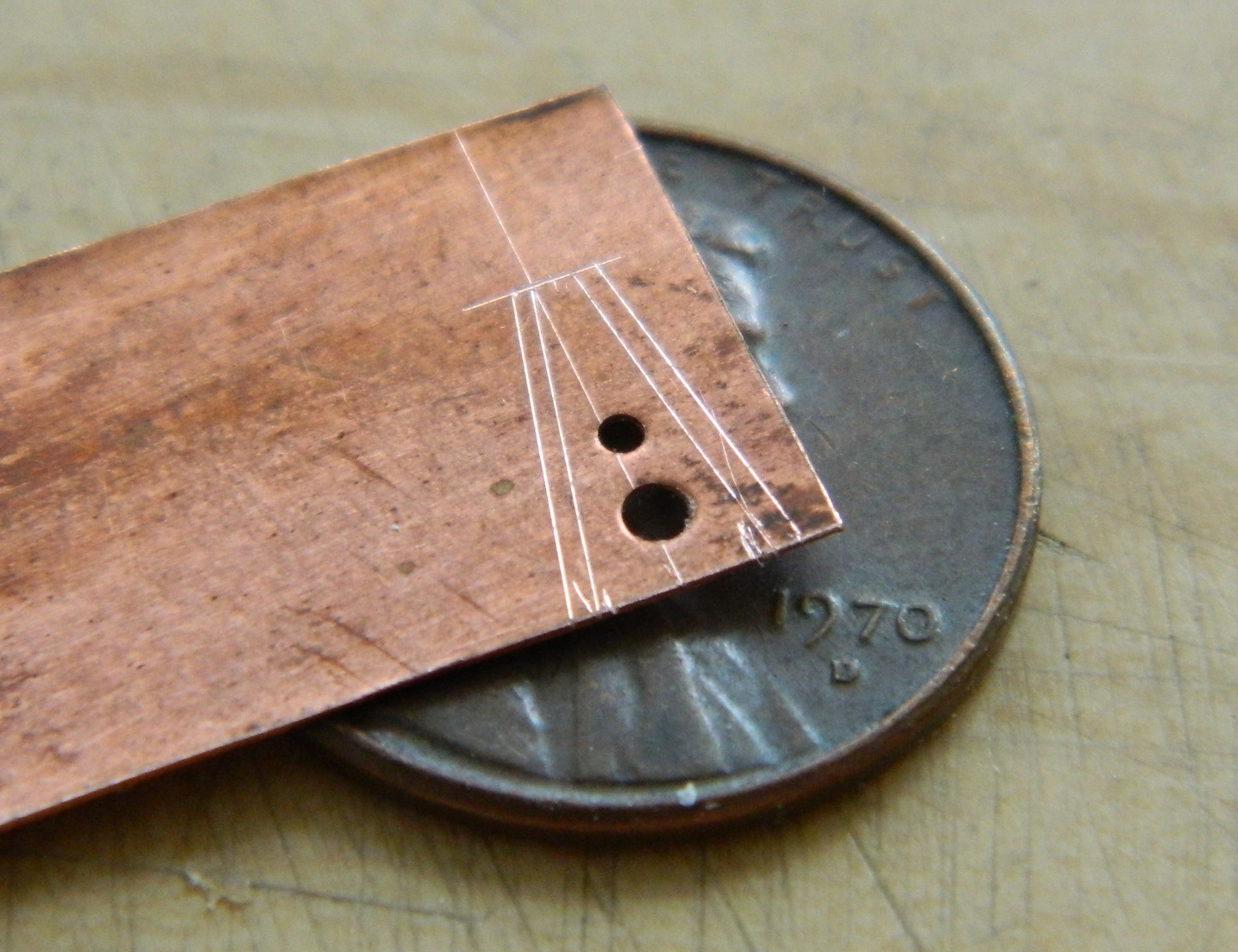
Once laid out, I cut the parts out using a sharp pair of scissors and then annealed the parts to make the bends easier and enable a smaller radius:
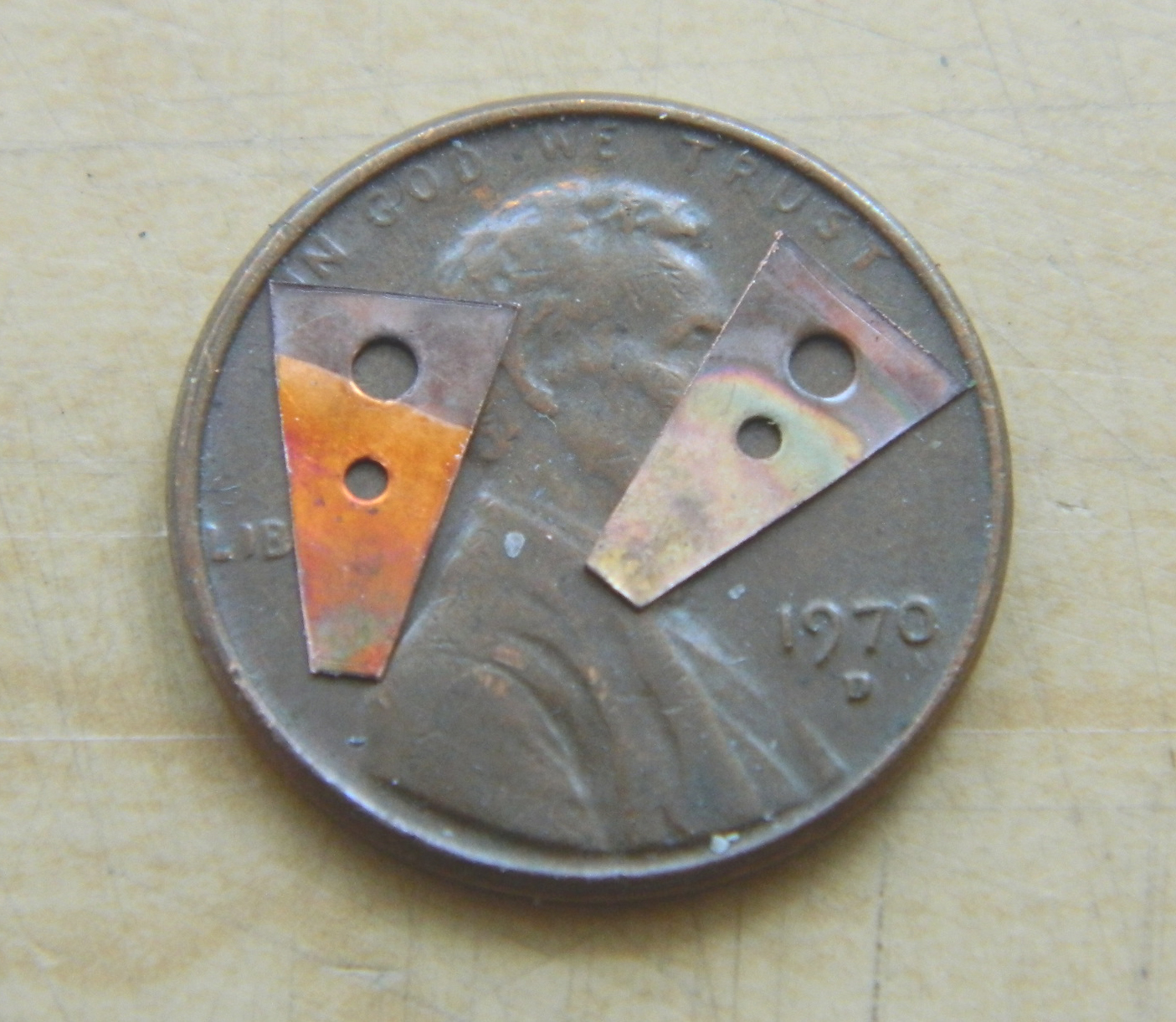
Naught left to do but bend them (he says as if it was easy…the first bend was easy…the second, well, not quite so much):
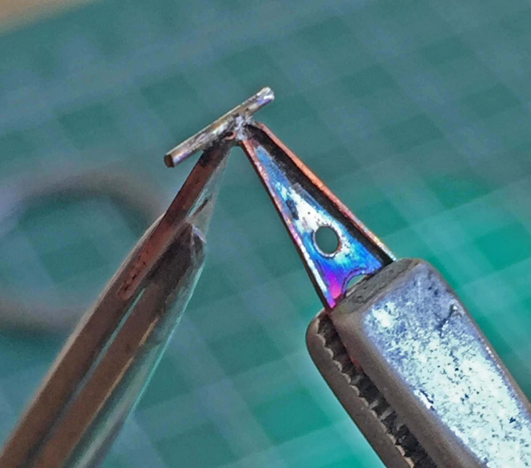
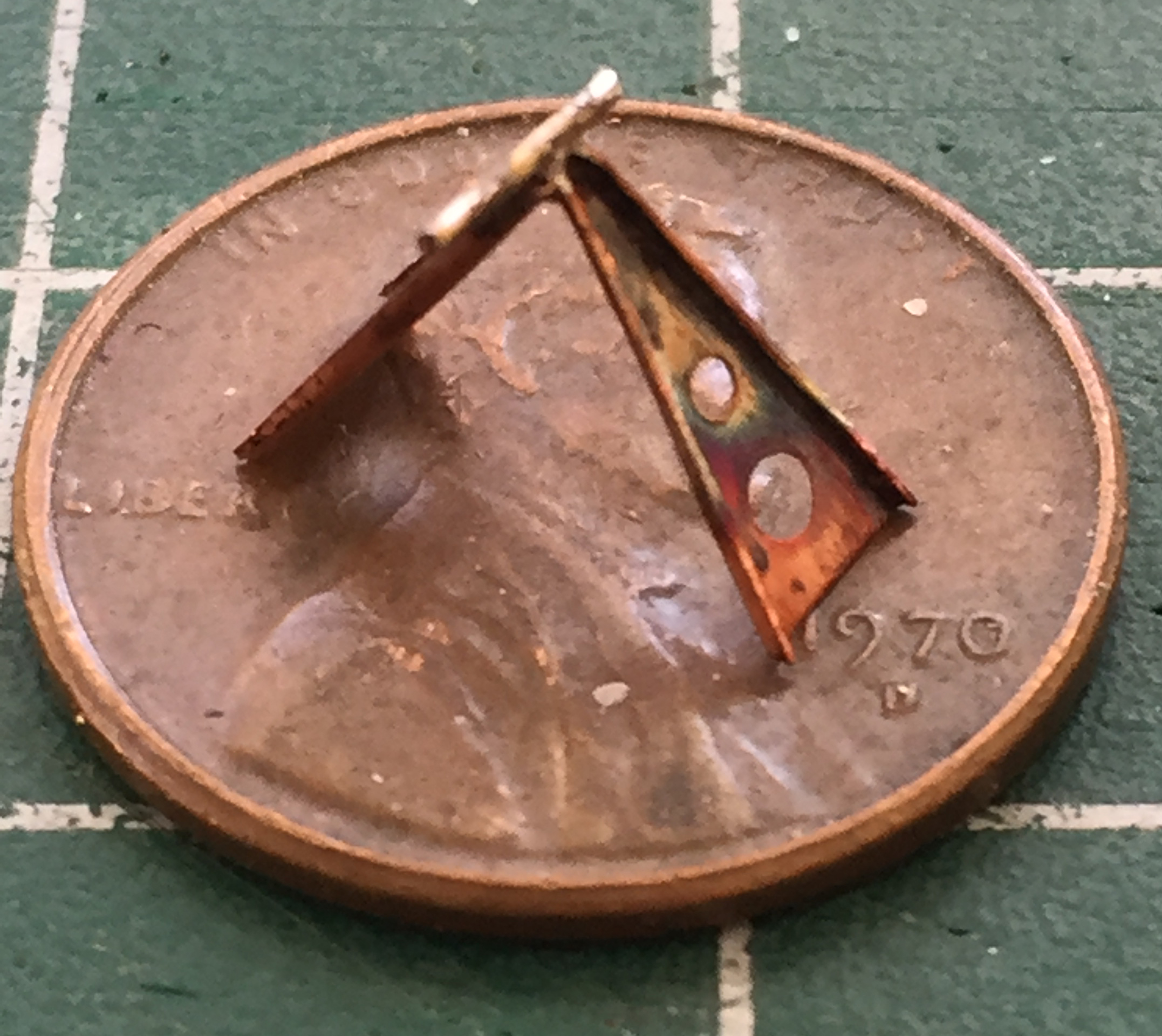
The extension limiters join at the small end. To replicate the hinge, I used a 22awg copper wire. The really interesting part of this was soldering them together. As most of the rest of the world, I only have two hands. To do this easily I would have needed at least three of them (or four, if you’re into bi-lateral symmetry) (I’m not judging). I used locking tweezers on stands to align and hold the two parts with just a little bit of overlap. This overlap created a “saddle” that I could place the wire on so that soldering it in place was at all possible. Using a butane torch would be challenging because the force of the torch’s gas flow could easily blow the wire across the workbench. To successfully solder this without causing the wire to go elsewhere, I approached the join from a fair distance away and worked the flame back and forth as I (SLOWLY) brought the flame closer. Once the flux melted, I knew I was close. Then the solder melted and I quickly moved the flame out of range. Whaddya know…it worked (I trimmed the wire to length once everything cooled):
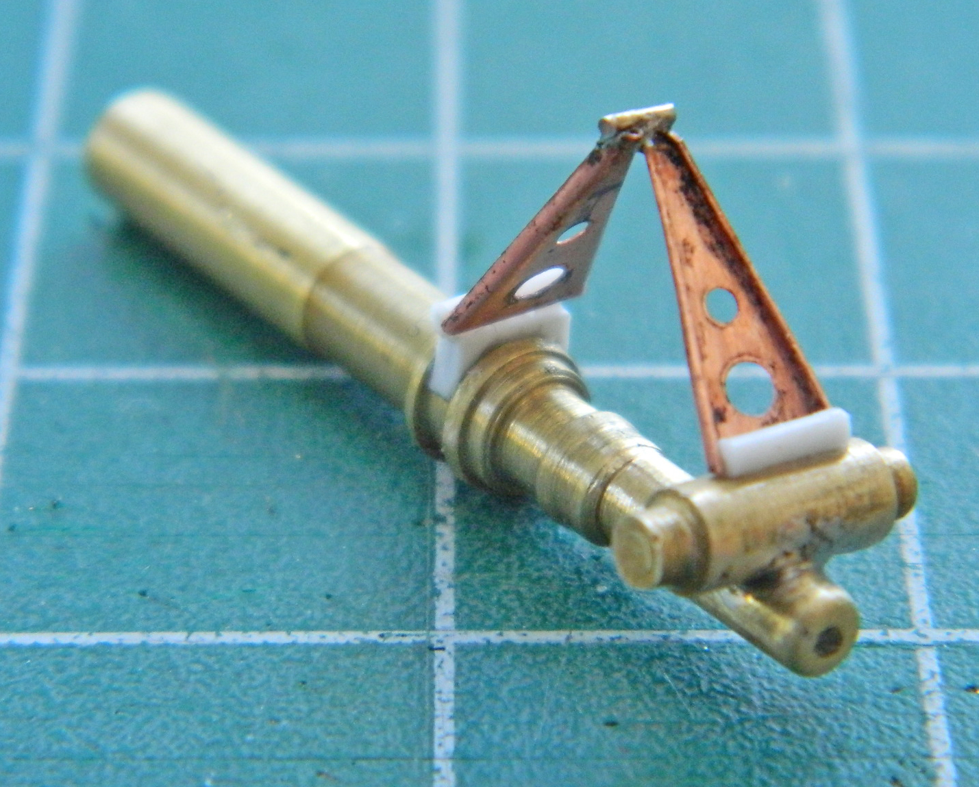
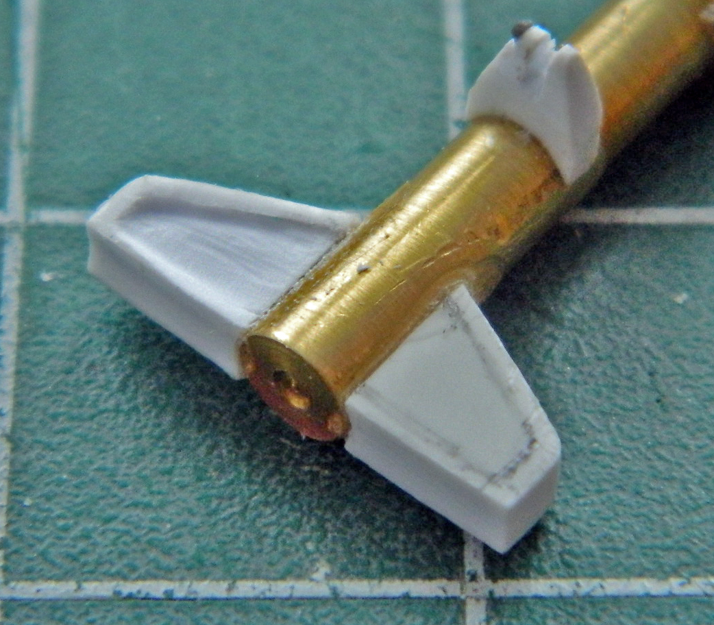
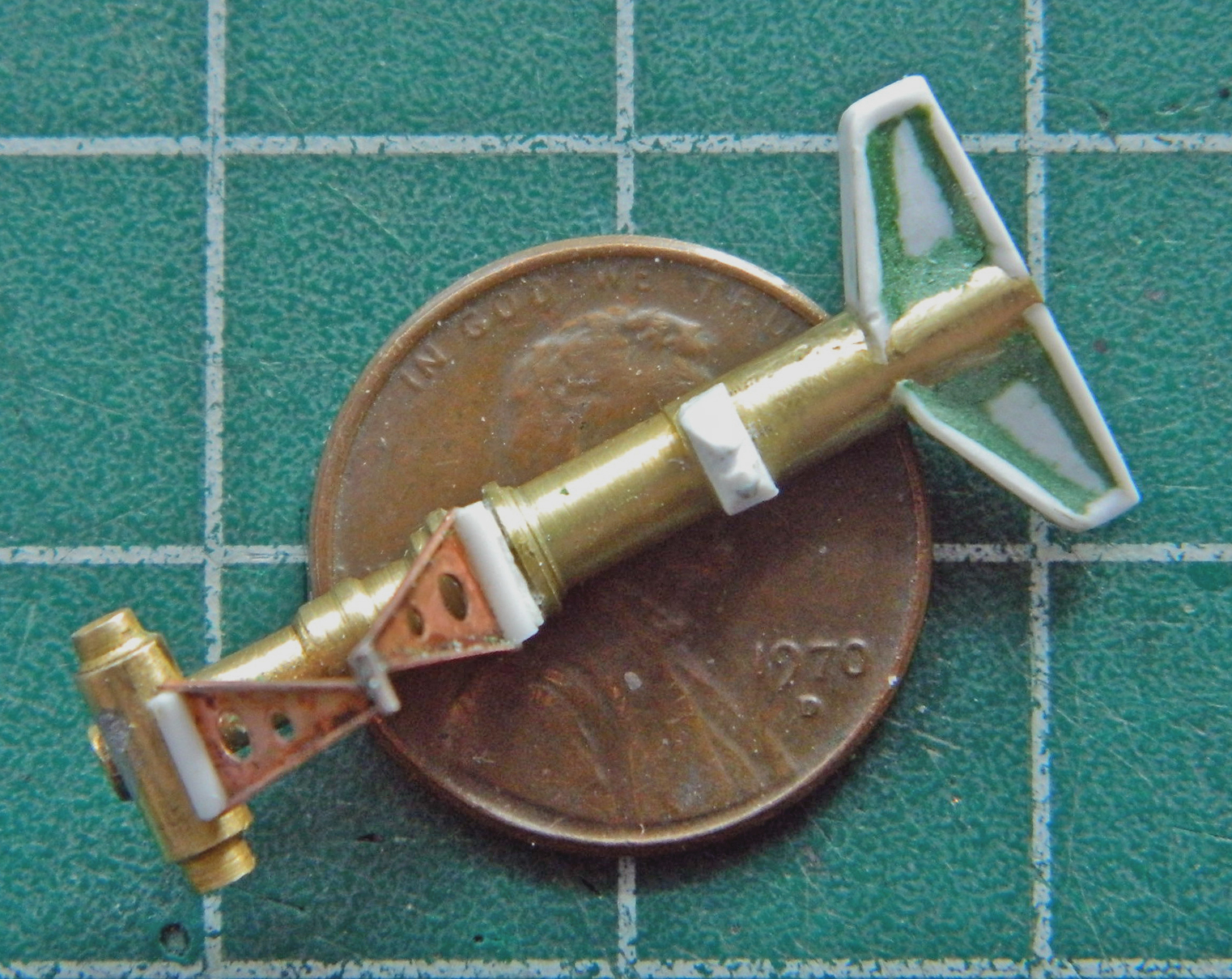
The extension limiters mount to the top and bottom sections of the front strut. I replicated that using small diameter styrene rod, superglued the rod across the wide end between the bent lips, and glued the extension limiter to the strut. (And where did that nice brass landing gear strut come from? I turned it on the lathe starting with quarter-inch [6.35mm] brass rod and without taking any photos of the process. Hopefully I don’t do that with the main landing gear struts):
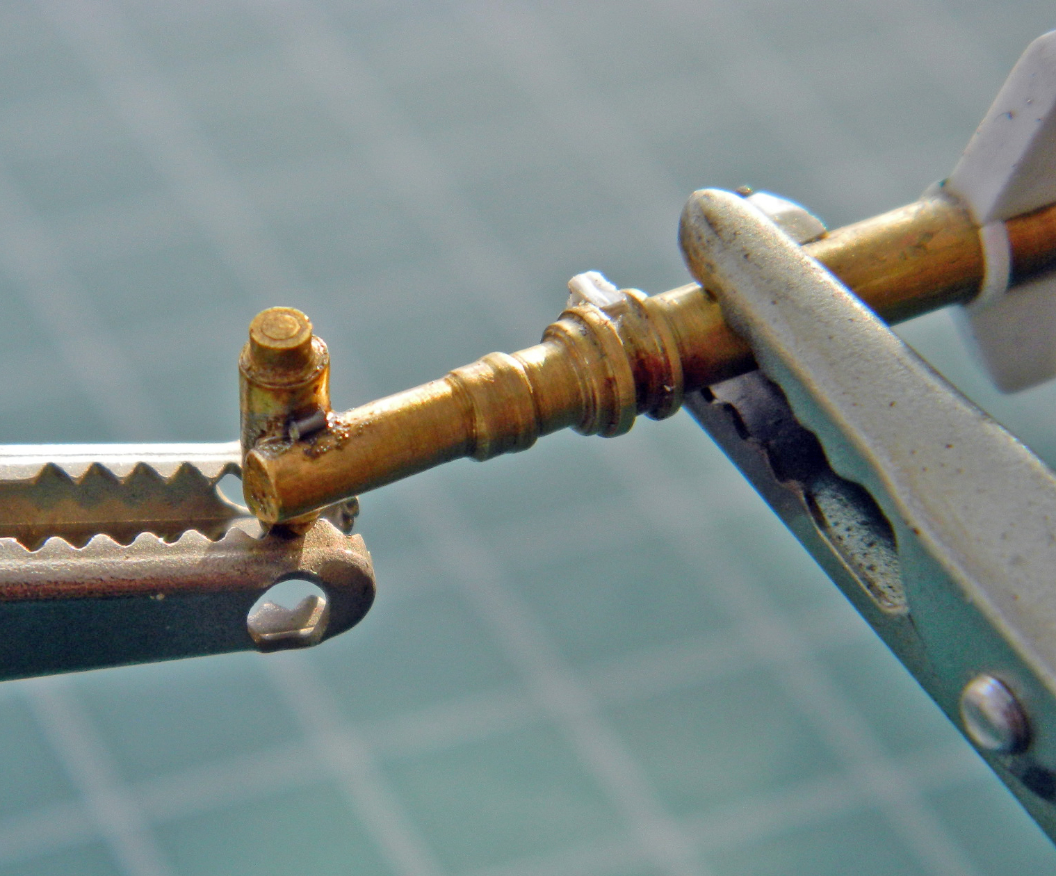
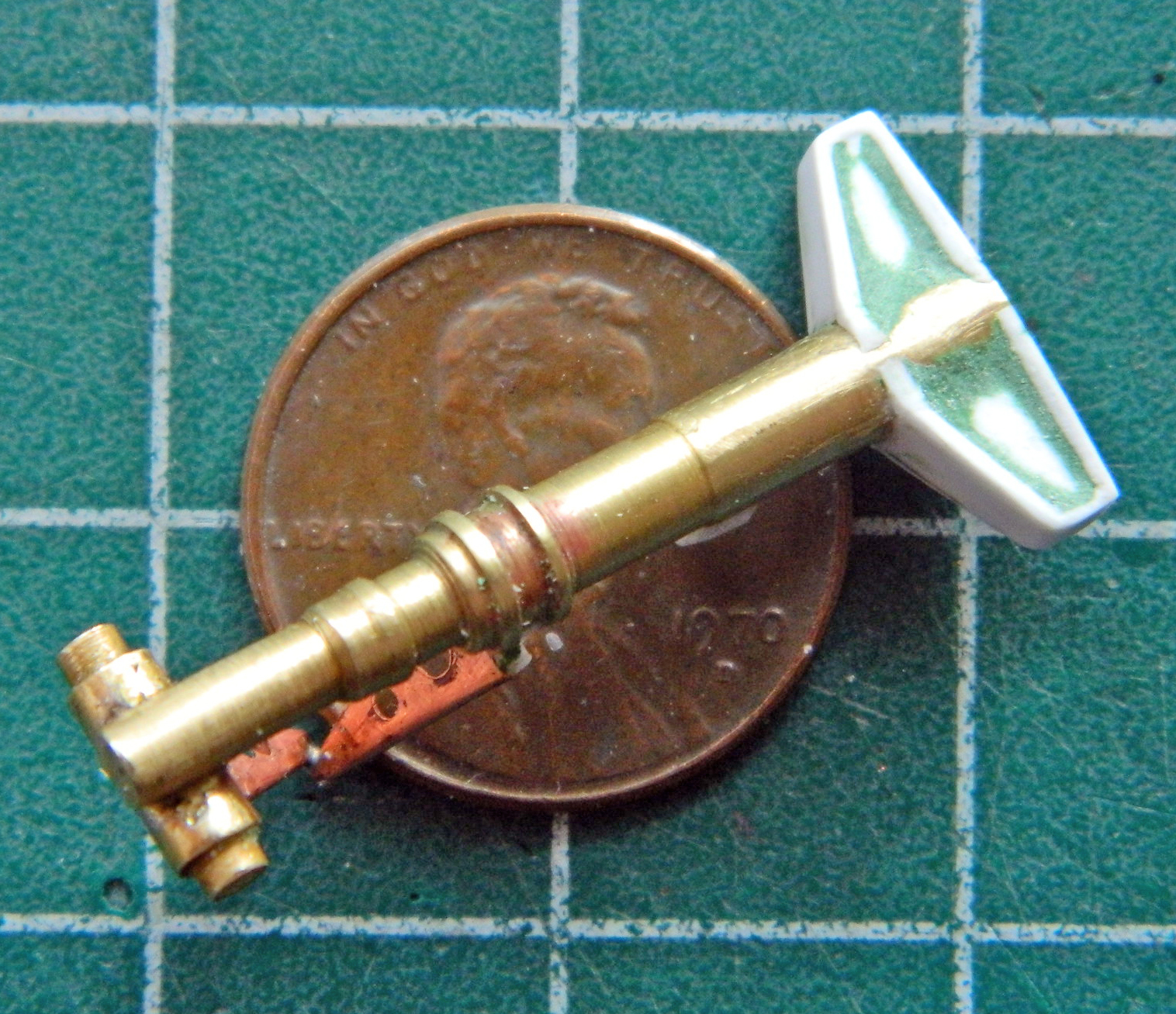
Flying if not high, at least off the ground, on my sense of accomplishment (that soldering job was very finicky and I did it successfully), I chucked a quarter-inch (6.35mm) brass rod into the lathe and turned the extension/retraction hydraulic cylinder, then added the hydraulic line. The restraining straps were made from aluminum duct tape, the line itself from 22awg wire. I amazed myself again by soldering the rounded mount at the left end of the cylinder in place (I filed the part round after soldering to ease the soldering process):

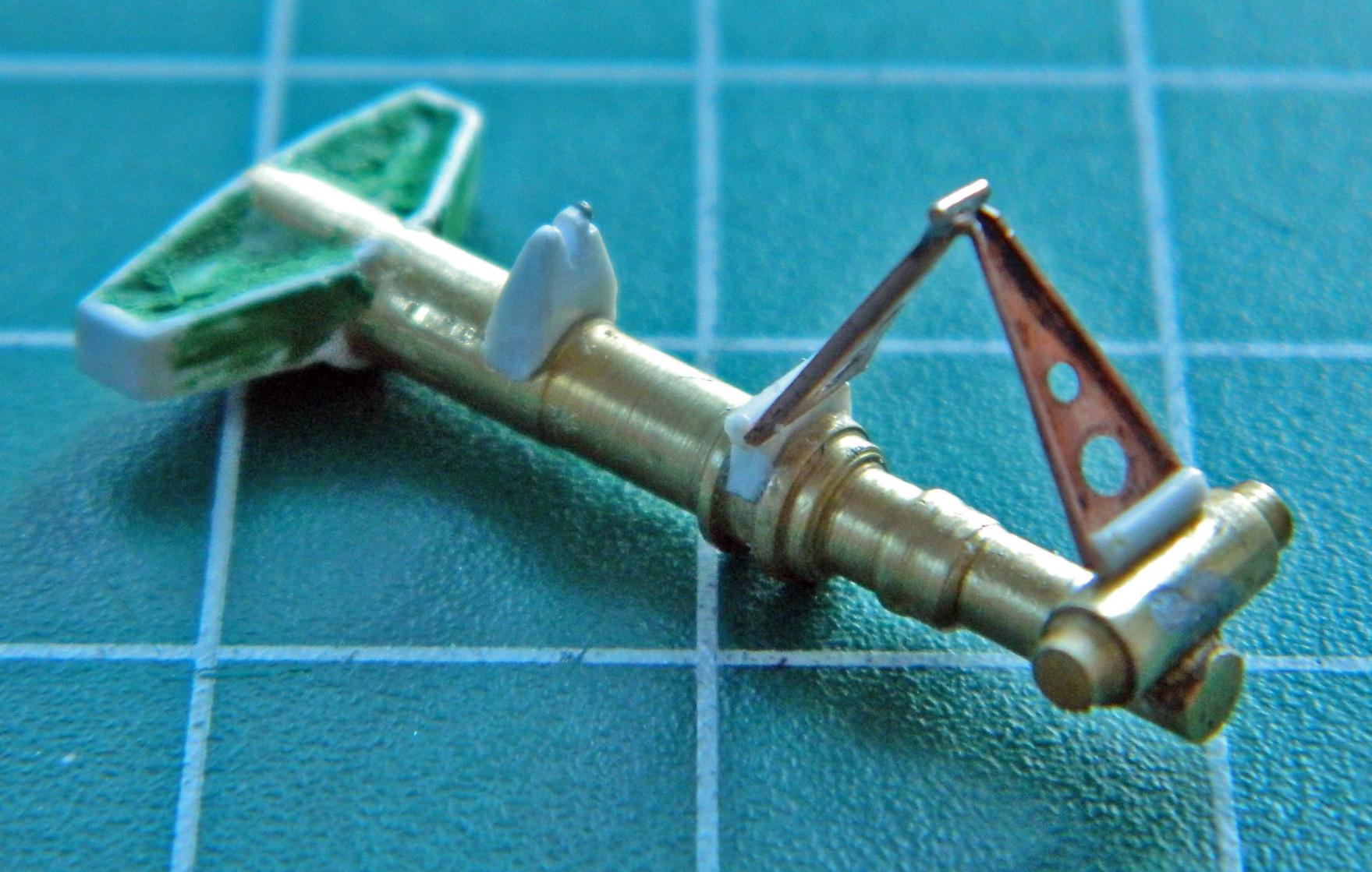
With the hydraulic cylinder done, I added its mount to the landing gear using .040″ (1.016mm) styrene and then checked its general fit:

Yeah…that gets it.
The front landing bay has three doors. The linkage for the rearmost of the three landing gear bay doors attached to the fuselage (wow, some surprise, there!) and to the nose gear strut. I constructed the door using .005″ (.127mm) sheet for the main section of the linkage, punched holes and connected them, and then added the connecting rods using 24awg wire, flattening the ends on my jeweler’s anvil with a hammer before gluing them into place (keeping in mind those will probably needed to be trimmed for correct fit later on):


I formed the landing gear door from .010″ (.254mm) sheet, curved it to match the curve of the fuselage, and then added the inner support structure using .040″ (1.016mm) styrene scrap. Once shaped, I blended the structure with putty. This may not be totally finished so if I need to add more detail later, later it will be added:
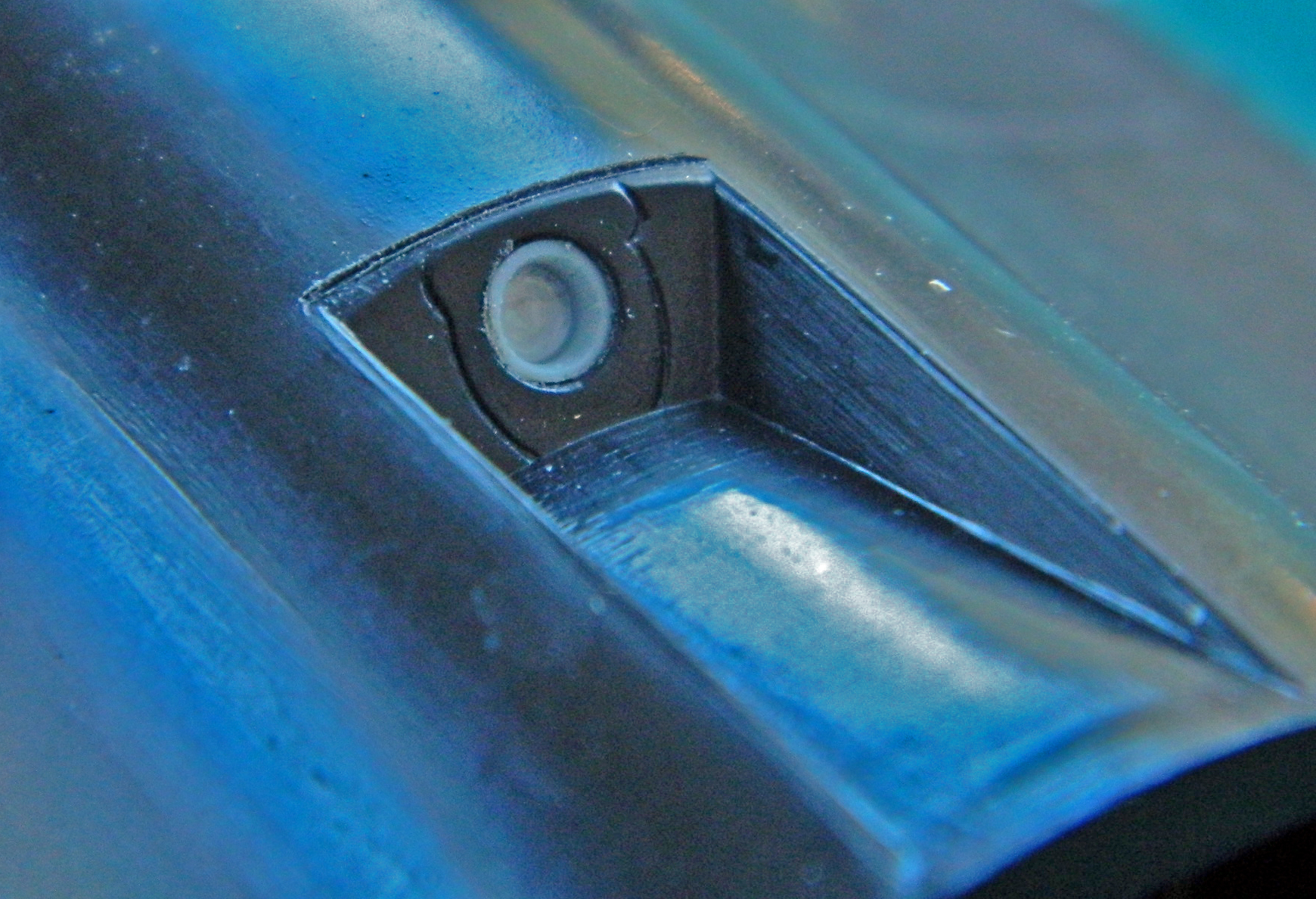
Stepping back from the landing gear construction, I fixed the errors of the mid-air refueling socket. The ramp that leads down into the fuselage is actually a hinged panel that swings up to close the port. The kit molded it incorrectly. It’s not supposed to be more narrow than the opening. The face where the refueling socket is looked correct to me, even if the socket itself wasn’t exactly a socket:
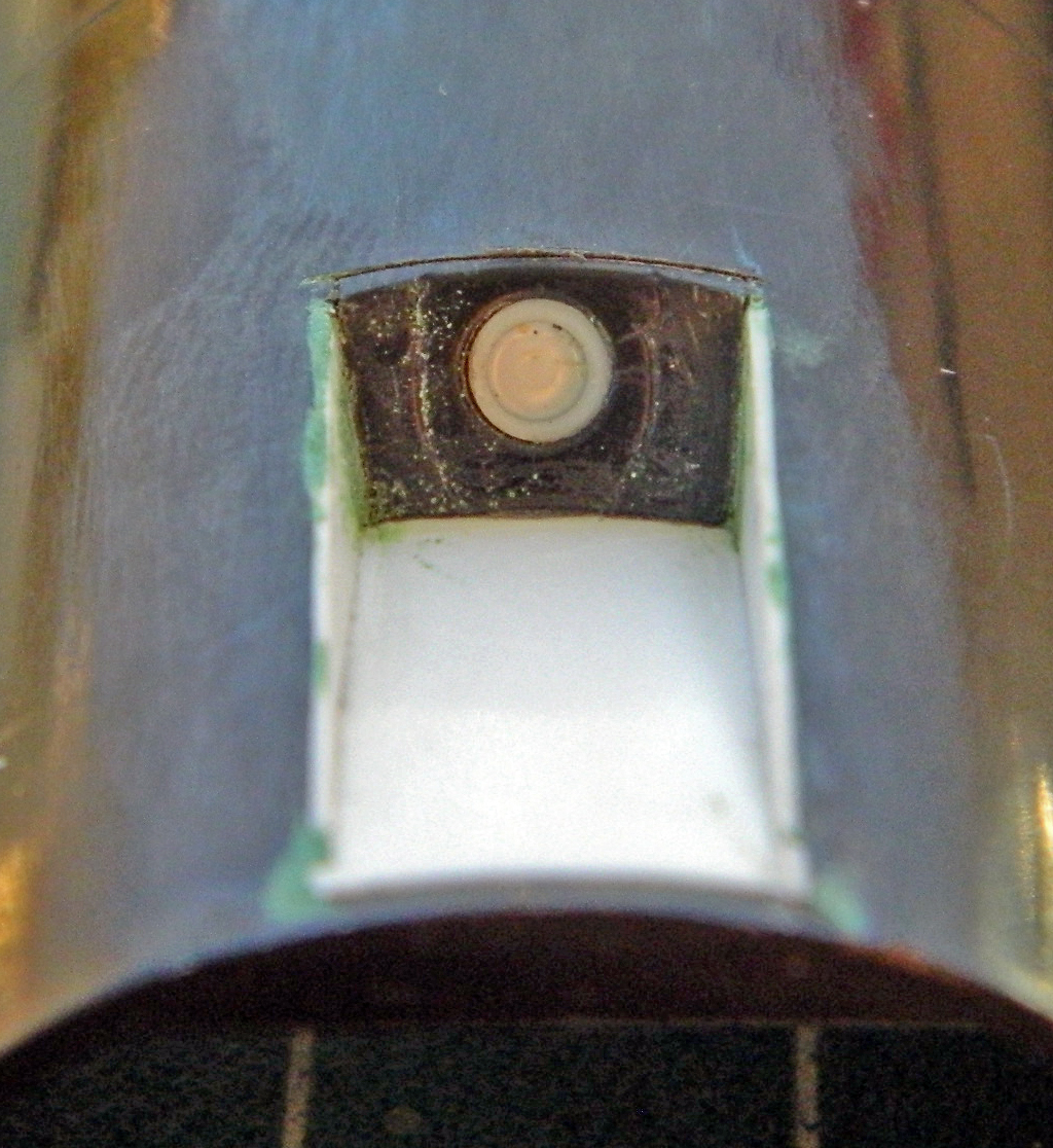
I drilled that out and widened the hole to the diameter I wanted with a rat-tail file. The closest styrene tube to that diameter was just a little bit too large in diameter and also needed to be drilled out to a correct inner diameter. I chucked it (GENTLY) into the lathe and turned it to diameter, and then drilled out the center. I cut a plug from .020″ (.508mm) styrene and inserted it into the drilled out center and glued it before gluing the whole thing into place:
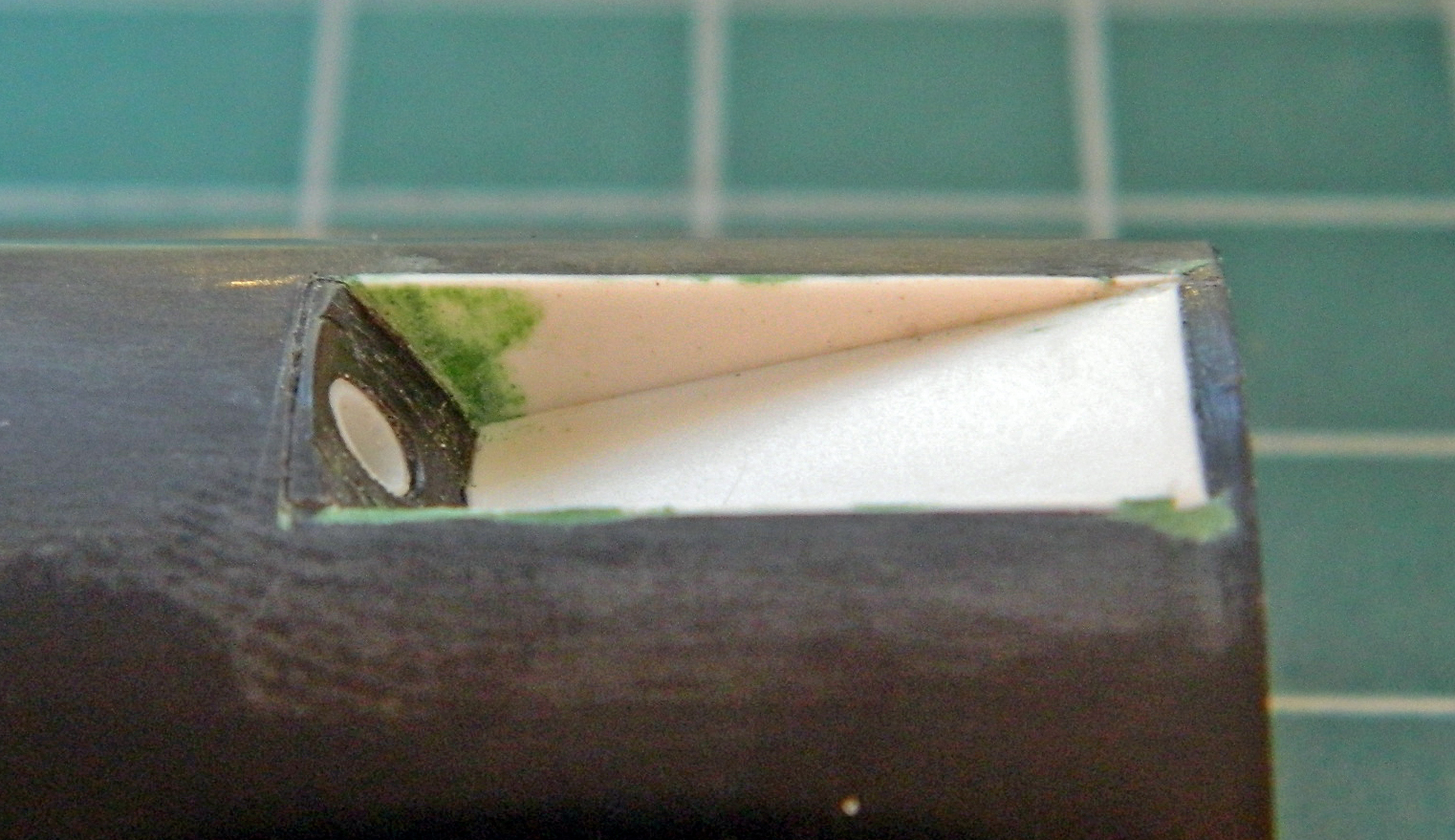
I cut away the molded-in structure and added the new structure. I started with the hinged ramp using .020″ (.508mm) styrene. I cut it to the dimension of the now-open hole and used the top of the fuselage (and HOT water) to form the ramp/door to the correct curve. Once satisfied, that was glued into place. I used more .020″ (.508mm) styrene to form the sides:
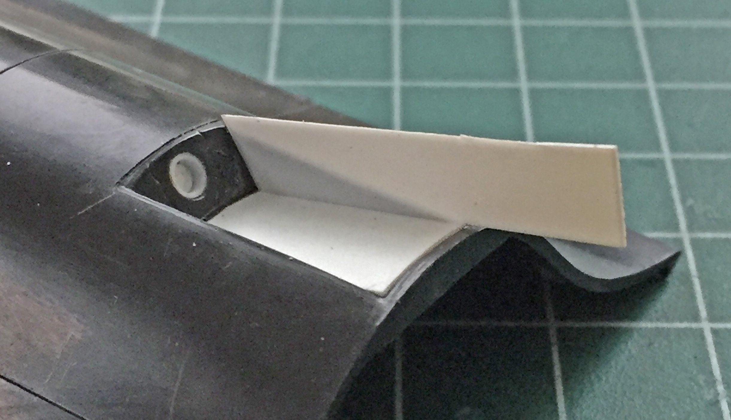

A little bit of putty, a little bit of sanding, and the result looks much better, now:

One prominent feature of the front landing gear is a large casting that forms the trunnion. I started with .060″ (1.524mm) styrene, shaped it, and then got to deal with the VERY FIDDLY alignment. I’m not sure I believe how long it took (over a couple of days, because sometimes stepping away to refresh the eye is a good idea) so I don’t expect you to. But eventually I got the parts aligned and (finally) glued:

The trunnion casting has a specific shape that I wanted to replicate. To do this, I started with an outline around the area I needed to carve a recess into and scraped the depression into the face:
I started adding the plastic that would give this part its shape:

Luck plays a factor in a build. If it’s bad luck, colorful invective is exercised, and if it’s good luck, well, I just take it and motor on. Funny (sometimes hysterical) thing about good luck is that sometimes it presents itself as bad luck. In the course of holding this assembly while I carved and scraped, the crossbar (that I spent HOURS getting aligned) snapped off.
In addition to all the colorful invective produced thereby, I also realized that this was probably a good thing. If that crossbar snapped off now, that meant it wasn’t soldered on well. That means if it didn’t snap off now, it would probably do so later after this thing was painted and finished. Fixing THAT would be…well…I don’t know as I have a pejorative foul enough. “Not easy to do” is a gross understatement. So my seeming bad luck turned out to be good luck.
That good luck was not quickly evident. Soldering, which is what I would need to do to get the crossbar reattached, involves heat. It involves enough heat to melt styrene. There is more than one piece of styrene on this part, one of which is much too close to where heat needs to be applied for my comfort. But without the crossbar attached, this piece is useless. If I screw up and melt plastic with the soldering job by using too much heat, then I’ll redo the plastic parts. Since it’s 100% useless as is, even with slim odds of soldering the part back on without melting anything, “slim odds” are better than “100% useless.” My journey into jeopardy started by snapping/cutting the extension limiter off.
This time I soldered the bitch on properly (twice, as the first attempt ended up with the crossbar misaligned) and didn’t melt anything! (I made sure of this by trying to wrench the thing off with pliers. Nope…it’s on there.):
There, just like it was never broken and repaired:

I added .040″ (1.016mm) strip around the upper and lower edges of the trunnion to complete the shape and filled out the surface with putty to replicate the casting:
The nose wheel steering is electrically operated and as such has a housing of a particular shape. That needed to be built (I left the “handle” attached so I could manipulate this bloody small part):
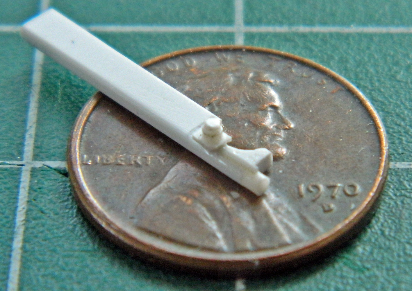
Once built, superglue attached it to the strut (well, I attached it to the strut…the superglue holds it there):

Now that I have the basic structure of what goes into the front landing gear bay…:
…maybe it’s time I should check to see if this thing fits in there:
Well, whaddya know…it fits like it was made for it!
Now that I’ve shown myself that I haven’t wasted the last two weeks, I can finish the nose wheel strut by adding all the other stuff that goes there (yes…there’s more). I started by making the landing light mounts. The mount for the larger light is on the right side of the strut and was made from .005″ (.127mm) shim stock. The smaller light is mounted centrally and was made from a drilled out piece of .030″ (.762mm) scrap:
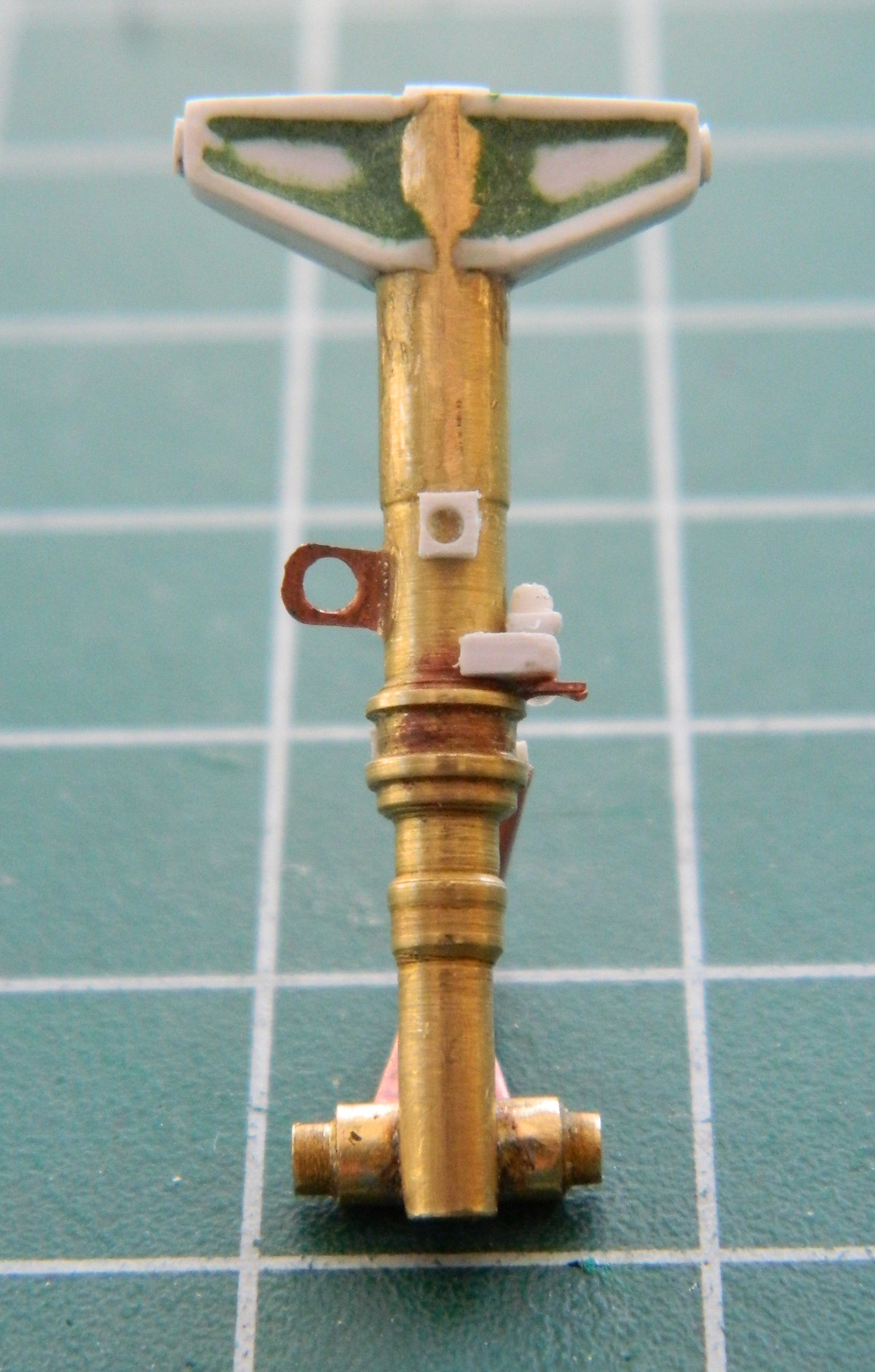
I placed the lights in place to see how they line up. For the most part, they do, I just needed to snap the central mount off and move it further down on the strut:
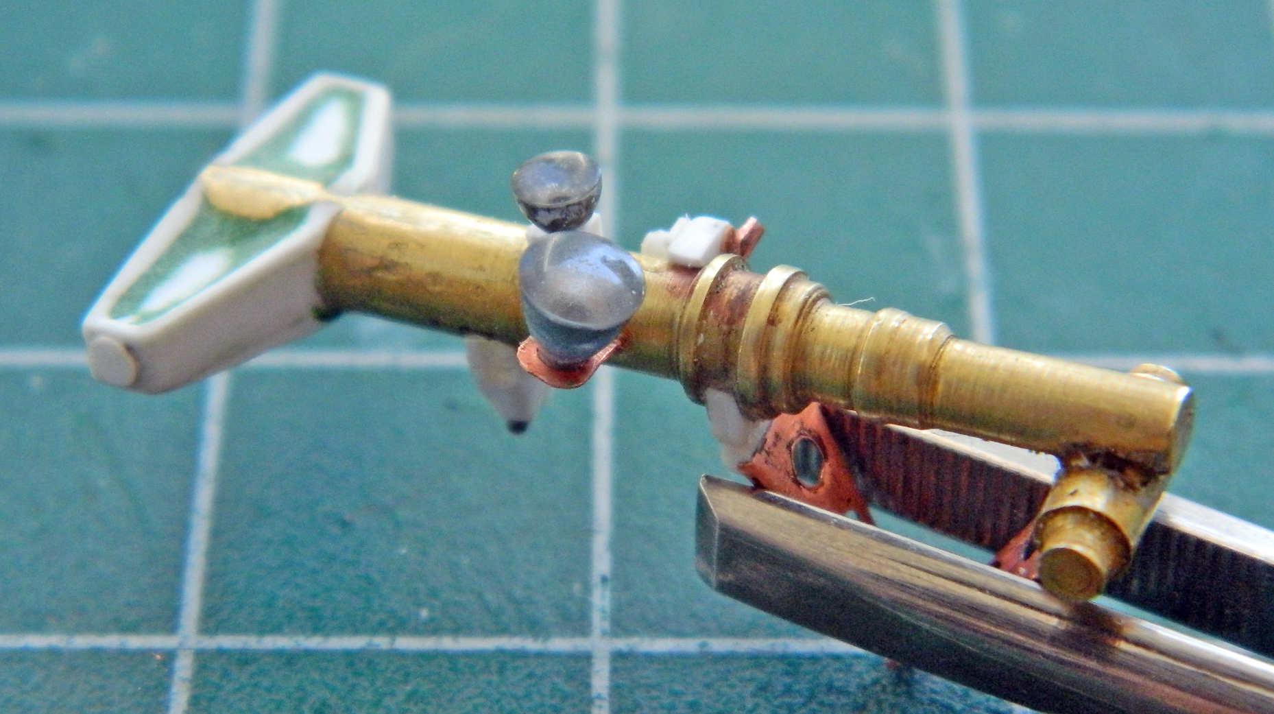

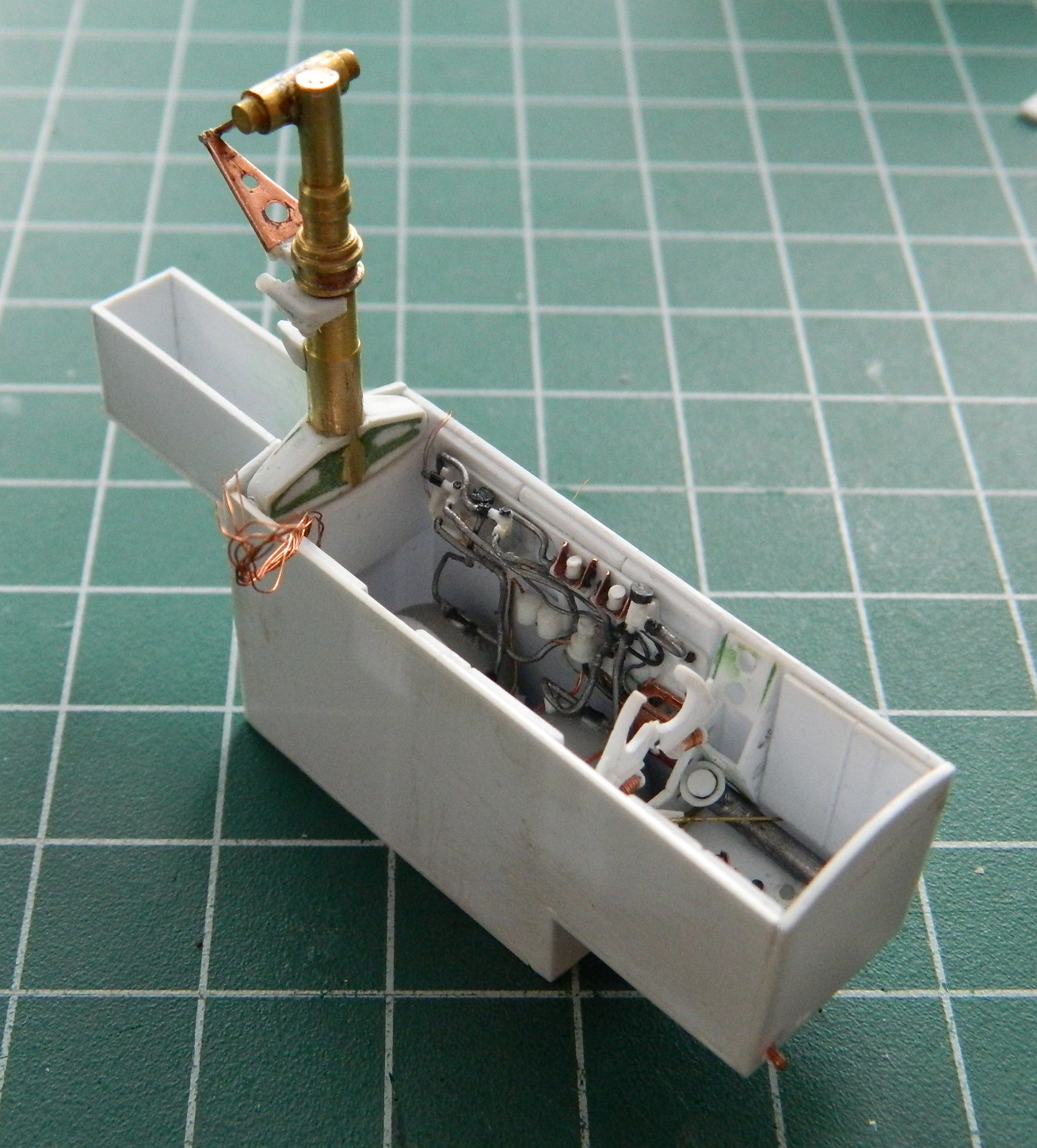
I needed to add the wiring conduit and wires. I used 22 and 24awg wires as well as .015″ (.381mm) solder and a pair of 40awg wires. Then I placed the hydraulic cylinder in place and took the next photos to show the differences between the kit part and what I cobbled together:

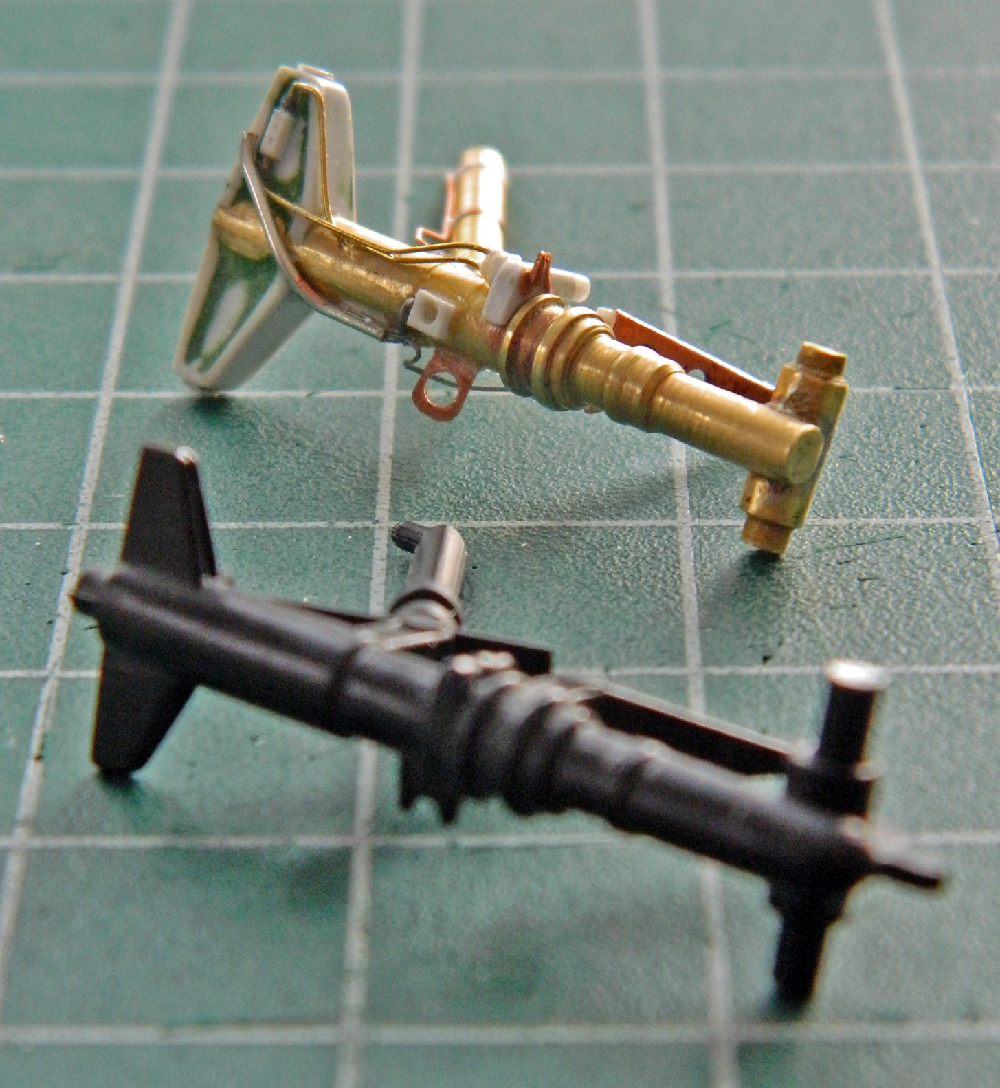
Clearly, though laborious and tedious (with a side order of frustrating), I think the improvement over the kit part was worth the time. Not counting the tires, of which there are two, this assembly required sixty-one separate parts to build.
One landing gear bay and landing gear is done, only two more to go. The “good” news is that I started with the more difficult assembly to make.
