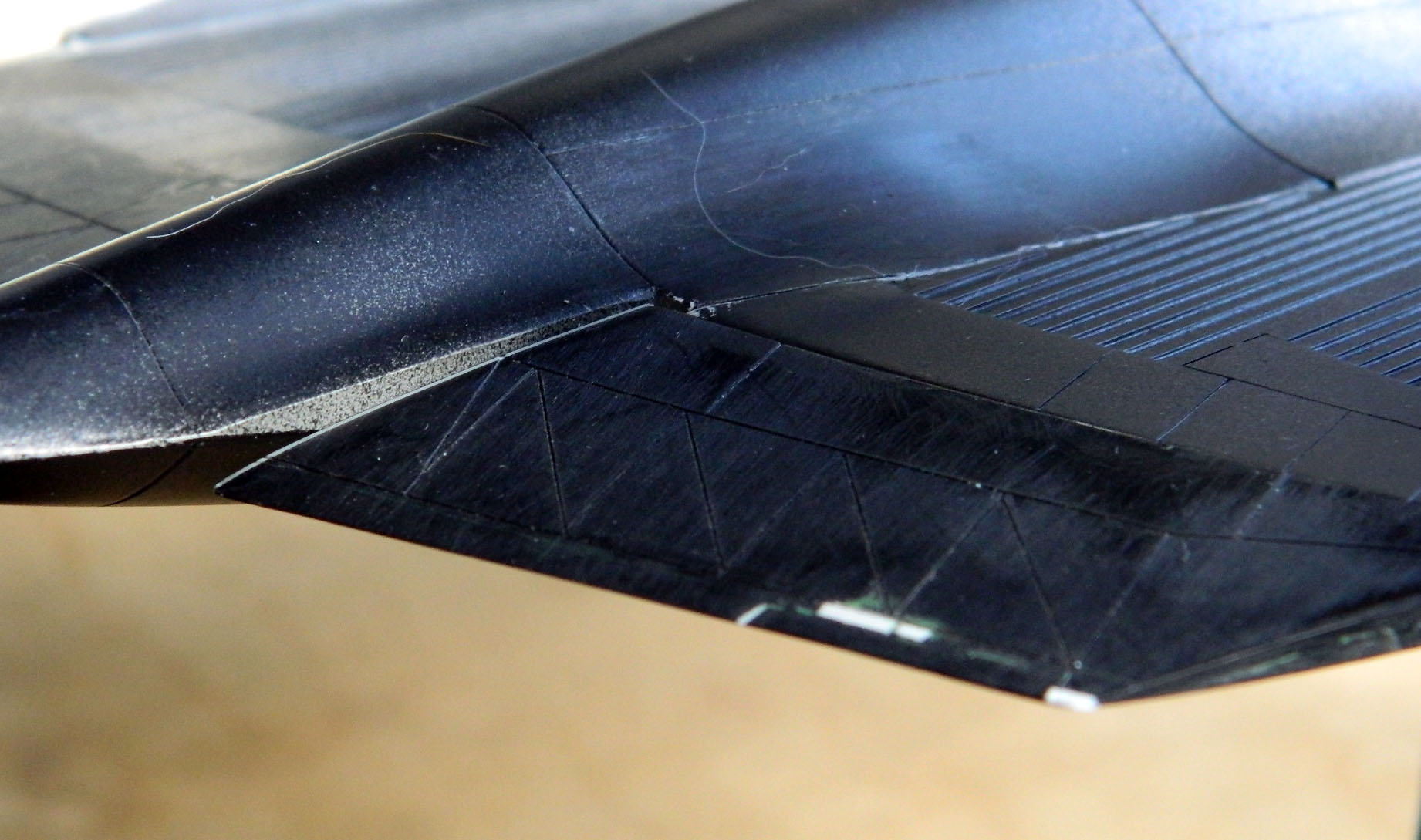
With the corners of the vertical stabilizers sharpened, it was time to add them:
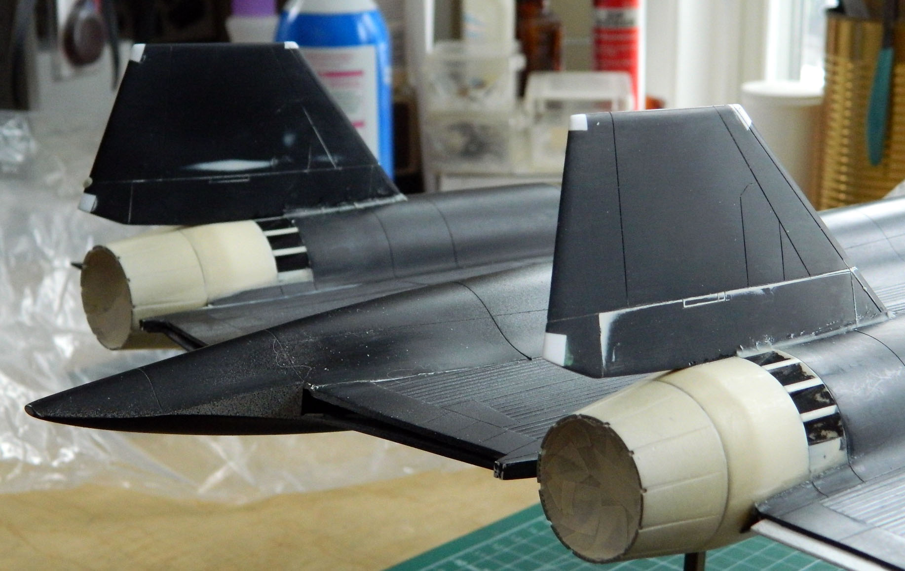
There isn’t a lot of surface area to bond the stabilizers to the nacelles so instead of adding green putty, which isn’t structural, I used epoxy putty, which is:

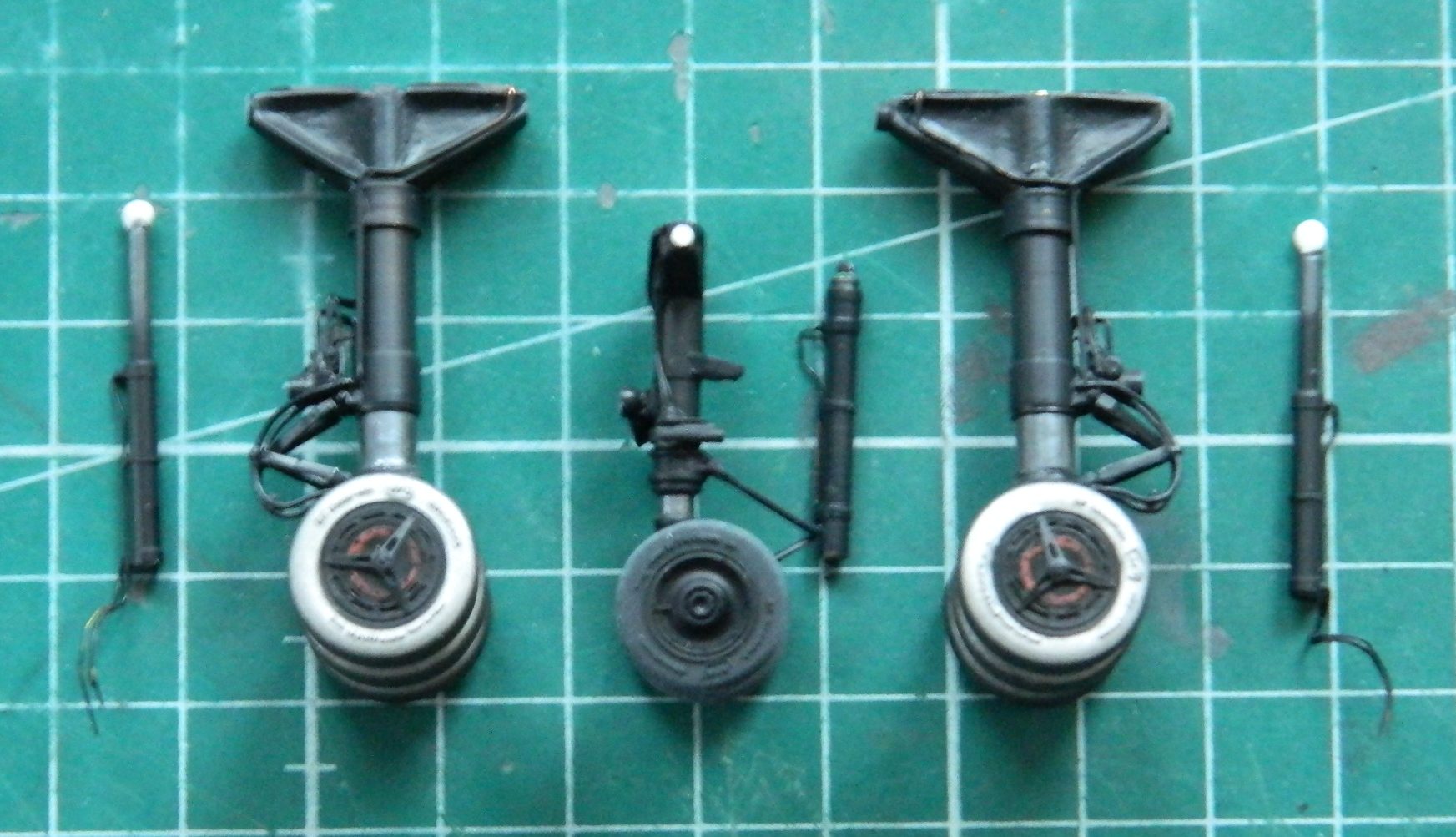
While the epoxy putty was curing, I pulled the parts out that needed to be painted and painted the landing gear parts:
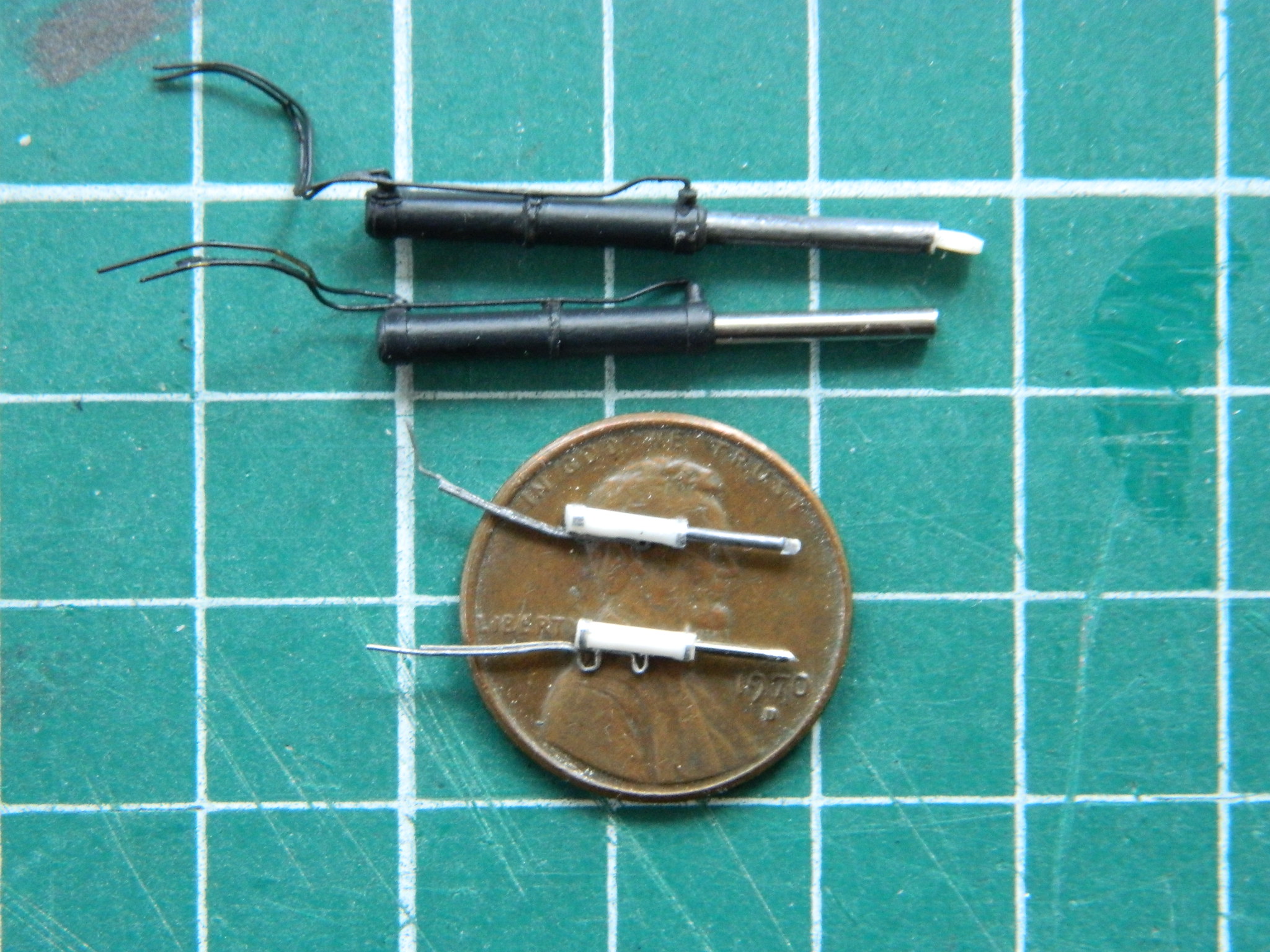
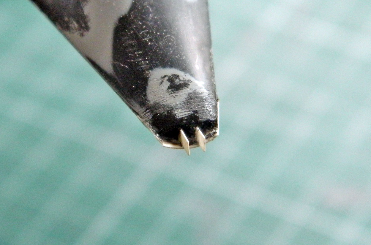
When possible, if I have to replicate a steel part, I try to use steel instead of steel-painted plastic. The difference is evident. The upper parts are the steel-painted plastic, its lower counterpart is steel. The large cylinders are landing gear parts (using steel welding rod), the smaller ones on the penny are for the canopies (using straight pins):
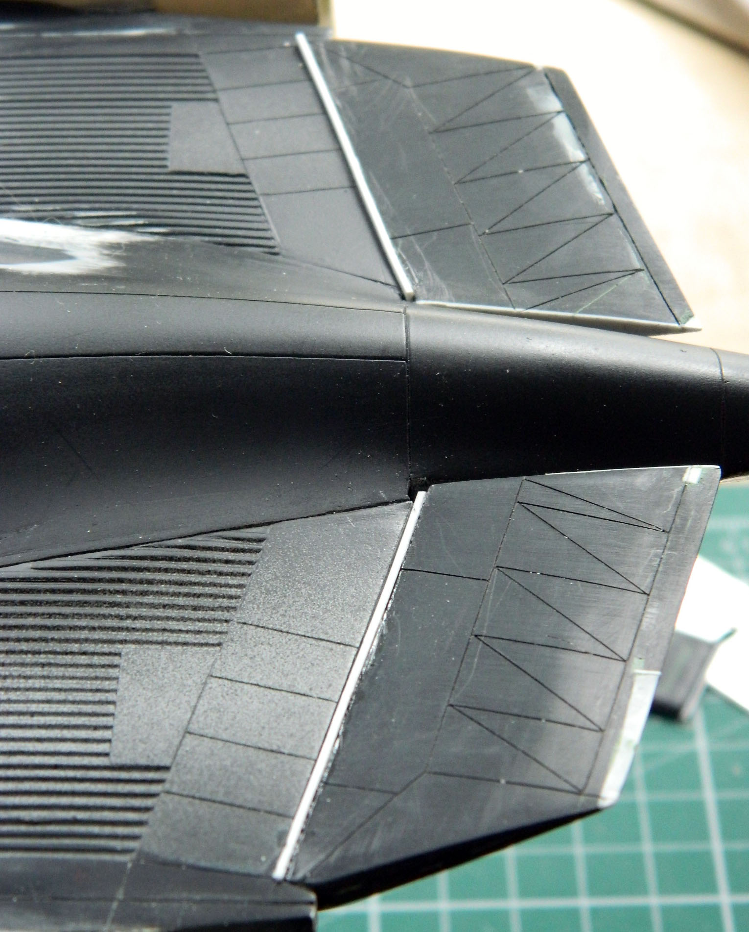
Then I needed to attach the control surfaces in the slightly-drooped position. Doing this offers more visual stimulation but I really dislike the task itself (frankly, I’d rather scribe lines) (spits). Once I had the inner control surfaces in place, the gaps on the lower sides had to be filled; I used styrene to do that:
I am SO GLAD when they are all done and added:

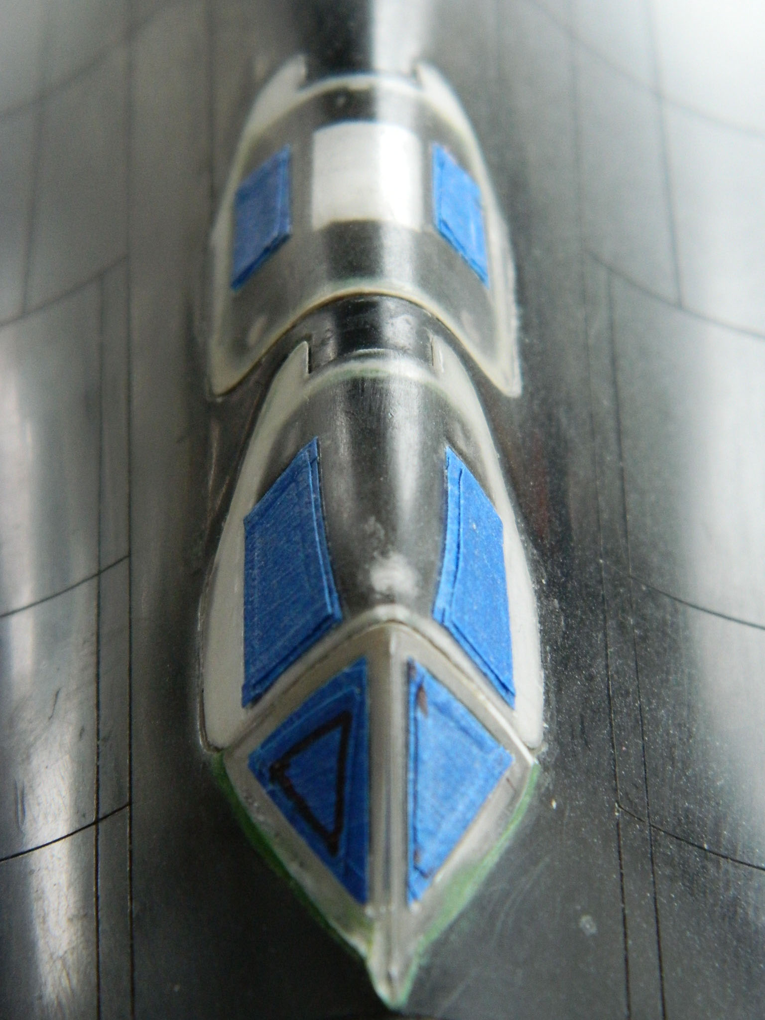
At this point I looked at where I had masked off the clear sections of the canopies. Then I realized I’d masked them in August of 2017. Oh bugger. Masking tape tends to separate paper from adhesive if the tape is left in place too long. Sixteen months qualifies as too long. It would be better for me to attend to that now before paint is laid down:

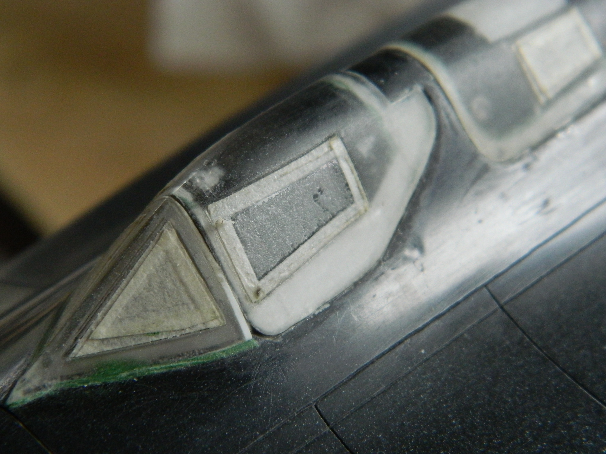
With the masking tape removed, a cotton swab dipped in lighter fluid dissolved and removed the stuck on adhesive left behind:

The next bit of masking tape won’t be there as long:

When I started to add the inlet spikes to the engine intakes, I was only half successful at first. The port (or left, if I’m not trying to impress) spike went in fine (or so I thought at the time…later on I discovered it had drooped a little before the glue set…and now there isn’t any way to fix that, so the next spike would have to have the same, inaccurate, droop). The starboard (or right, if I’m still trying to impress), however, managed to dismount its connecting point as I was pushing it into place. I thought I had that assembly well-glued, reality indicated otherwise. Aside from the obvious, the part that came completely disconnected is inside the nacelle:
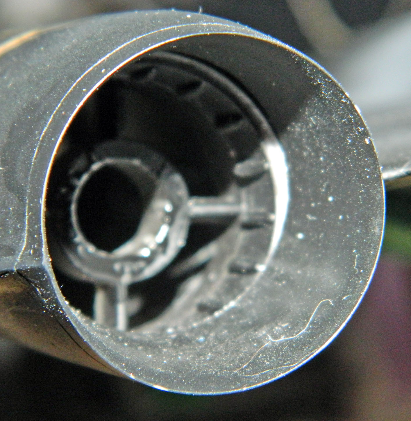
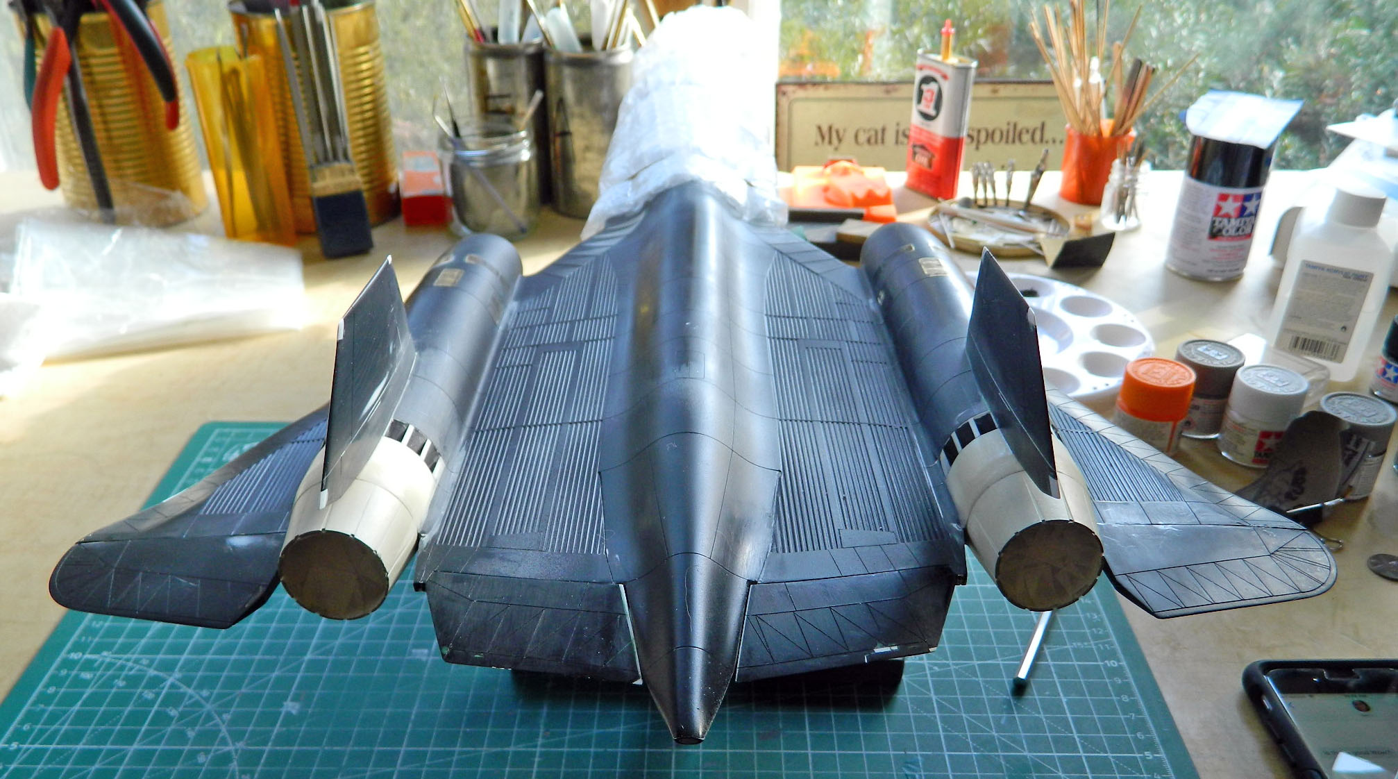
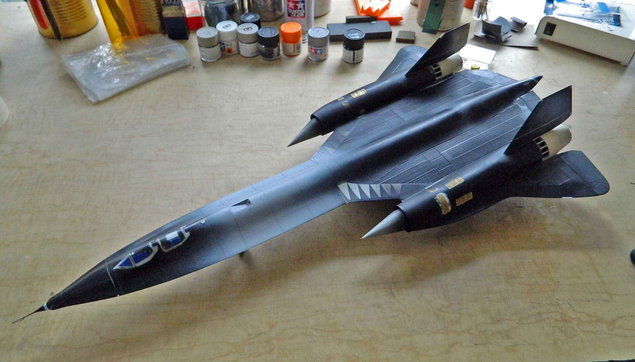
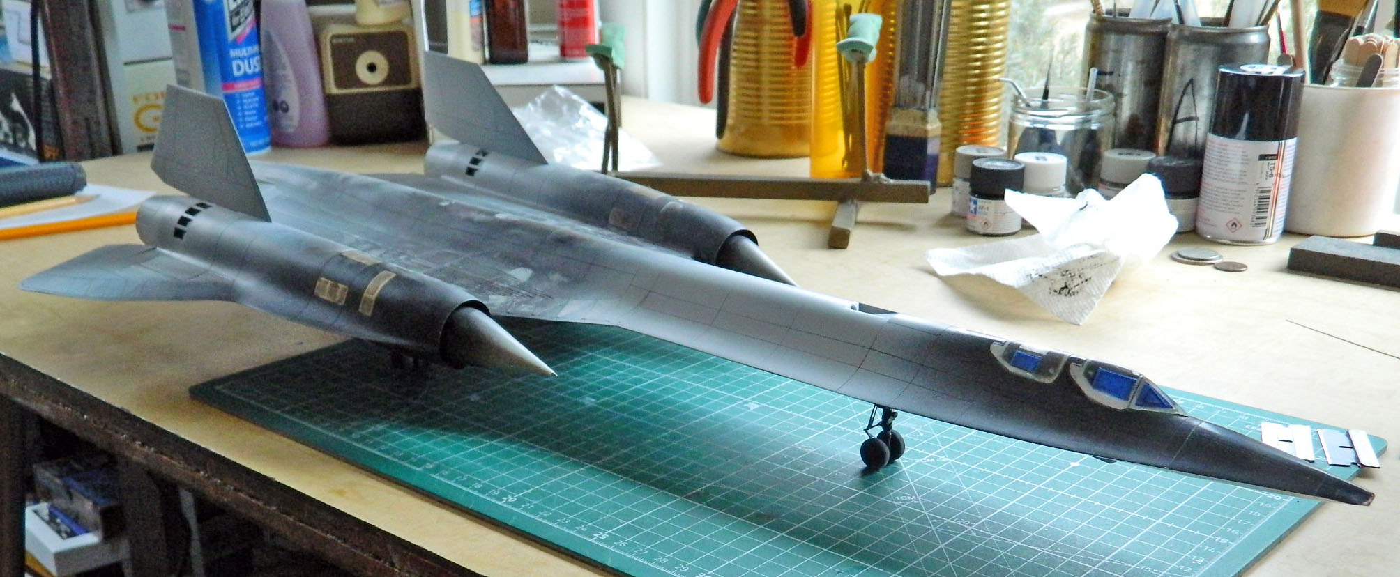
I was wroth and most vexed. Oh, and I was COMPLETELY LIVED as well. I came up with two possibilities that could fix the problem. The first was the most complicated (of course), involving cutting open the nacelle behind the spike mount and gluing it in place from inside. The second was simpler, involving taking a 1/8″ (3.18mm) brass rod and putting a 90-degree bend in it and using that to pull the mount forward into contact with its attachment point. I decided to try the simpler fix first this time, figuring that if it didn’t work, I could always cut the thing open later. I don’t know it it was exactly luck, but so far it seems to have worked. The inlet spike in the foreground is the one where its mount came loose (and by the way, isn’t this thing starting to look like an SR-71?):

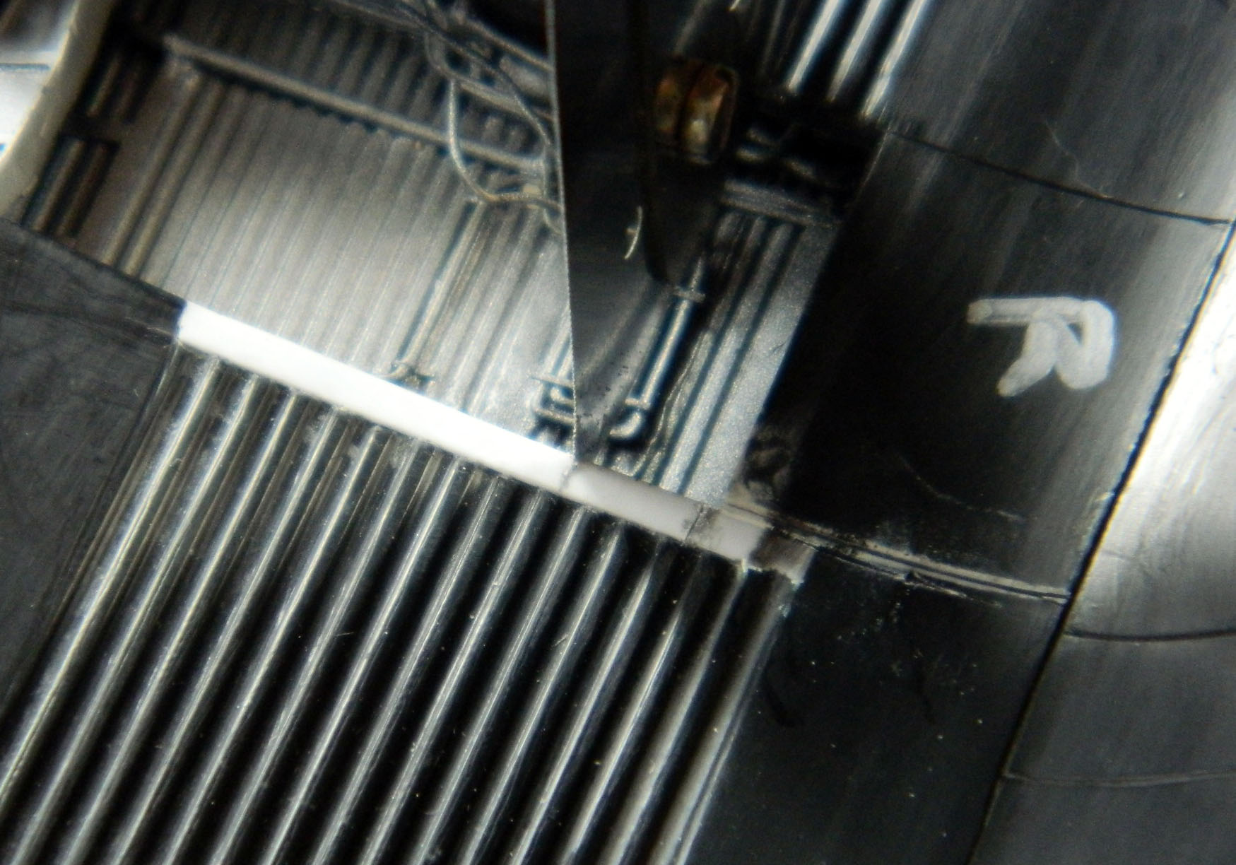
The next step was to attach the landing gear. Along the way, I’d dry-fitted the landing gear several times and each time I had no problem with fitting the trunnions into the landing gear bays. So with everything inside the bays painted and the fuselage parts all permanently attached, of course the sodding things won’t fit inside the openings; neither main landing gear does:


As there was NO “Plan B” to fit these things, my only option was to cut a notch in the fuselage to allow these parts to sit inside the bay, then to plug the gaps I’d have to cut…and so I did:

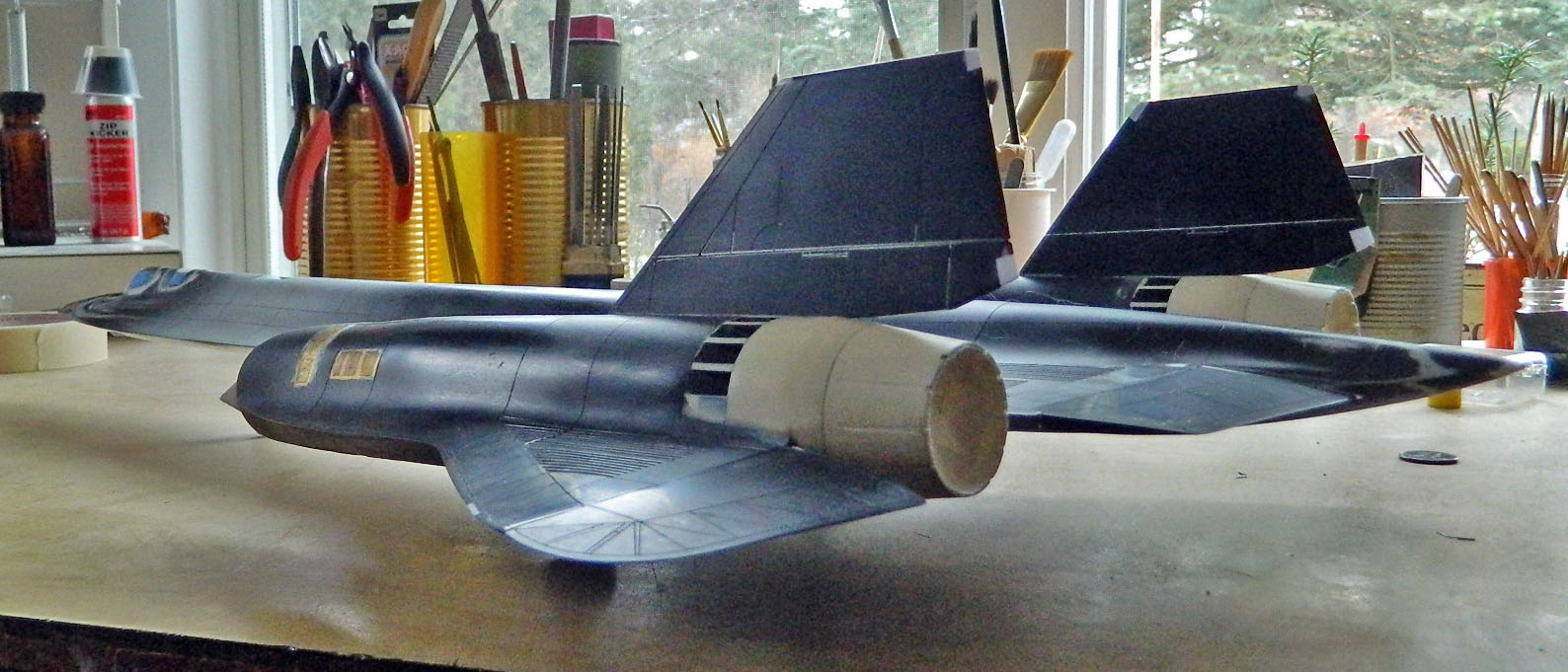
And fit they did. Here’s the beast standing on its own legs for the first time. That is a major milestone. The fly-filled ointment (hmmm…I wonder if I could use that as a filler…) is that evidently the cross-bar of the front landing gear, the part that the tires mount to, isn’t precisely perpendicular to the strut. If you look closely at the first photo and the left landing gear tire, you can see that there’s just a little bit of daylight under the tire that’s not supposed to be there:

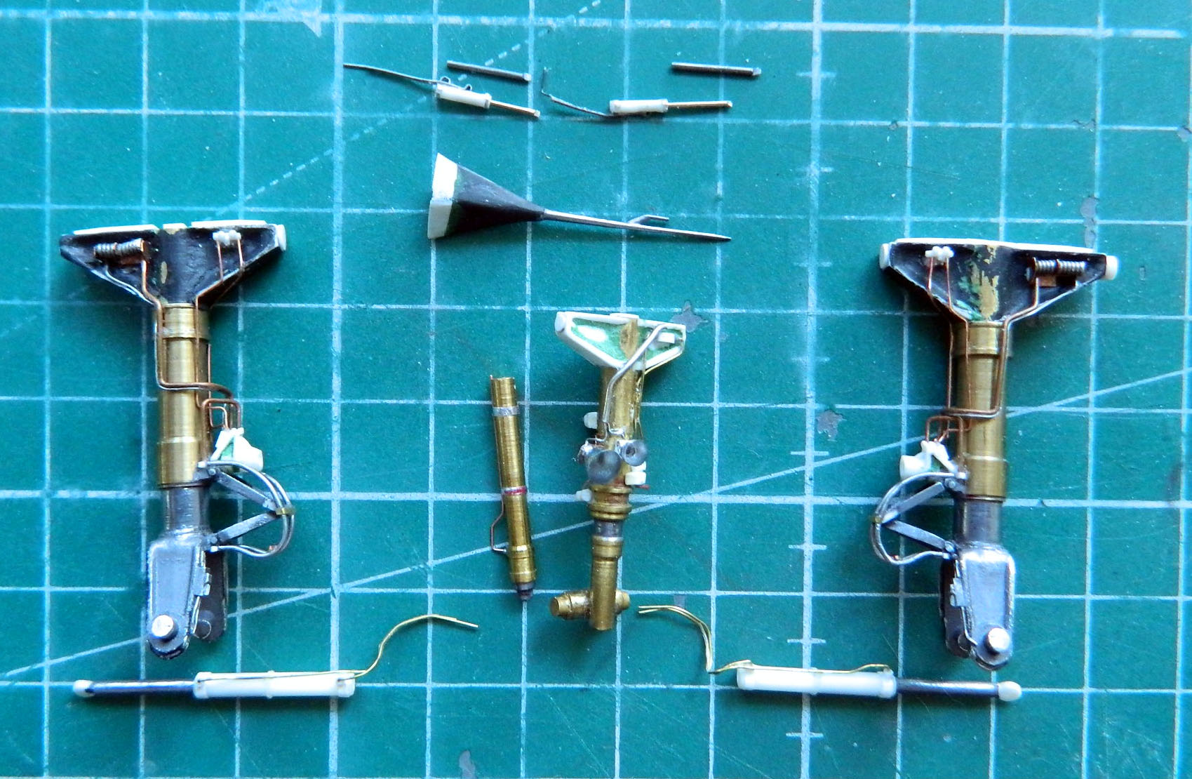
With the major landing gear components installed, the lines needed to be attached to them as well as the extension/retraction cylinders. The notion to allow the extension/retraction cylinder mounts to rotate and for the rams to slide a little worked perfectly:

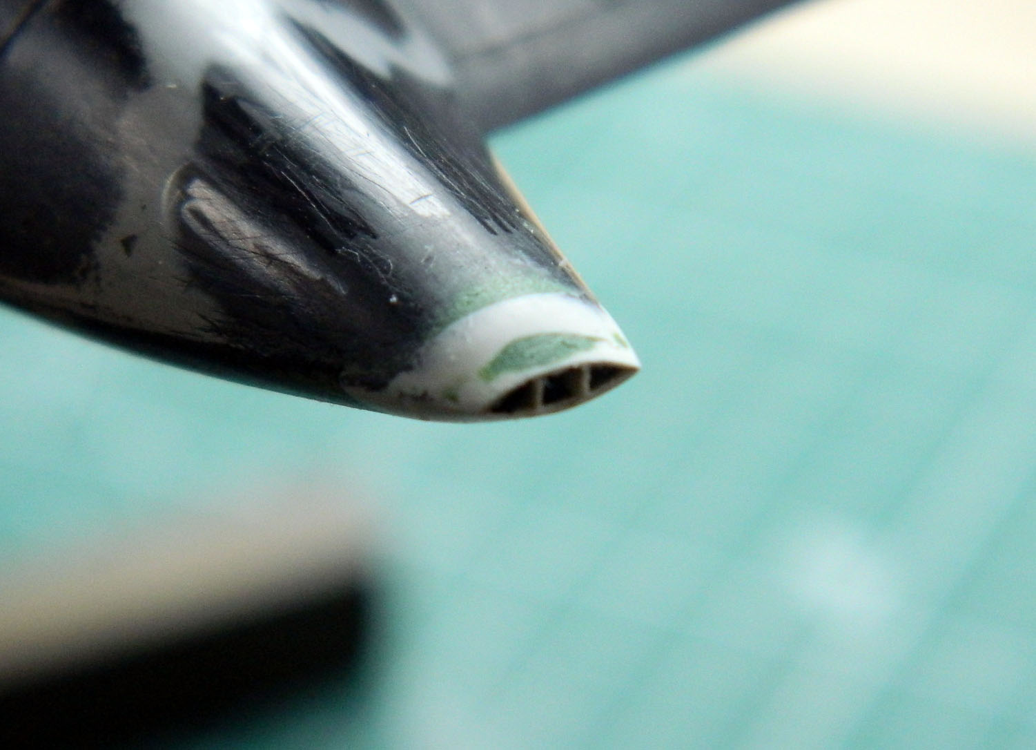
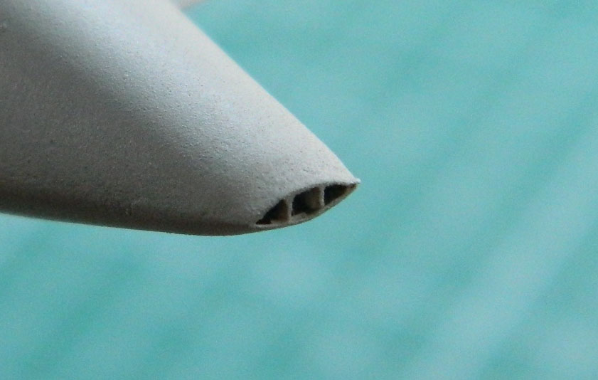
At the absolute tail of the fuselage are the fuel vents. The Blackbird had to deal with a weight limit on the amount of fuel it could have for its takeoff roll. If it had too much fuel on either its take-off roll or landing, the tires showed a disconcerting tendency to come apart explosively. Since this tends to be a specifically bad idea (not just for stability but because the early wheels were constructed of magnesium and magnesium burns MOST intensely…which tends to be bad for the paint job), takeoff fuel weight was limited to 80,000 pounds (36,287.39 kg) or less. Conversely, when landing, the weight limit was still the limit so if the aircraft was approaching with too much fuel aboard, the excess was dumped out of the fuel vents. The model has that section molded solidly, so the first task was to flatten the rear tip of the fuselage. Then I constructed this section out of .005″ (.127mm) styrene:

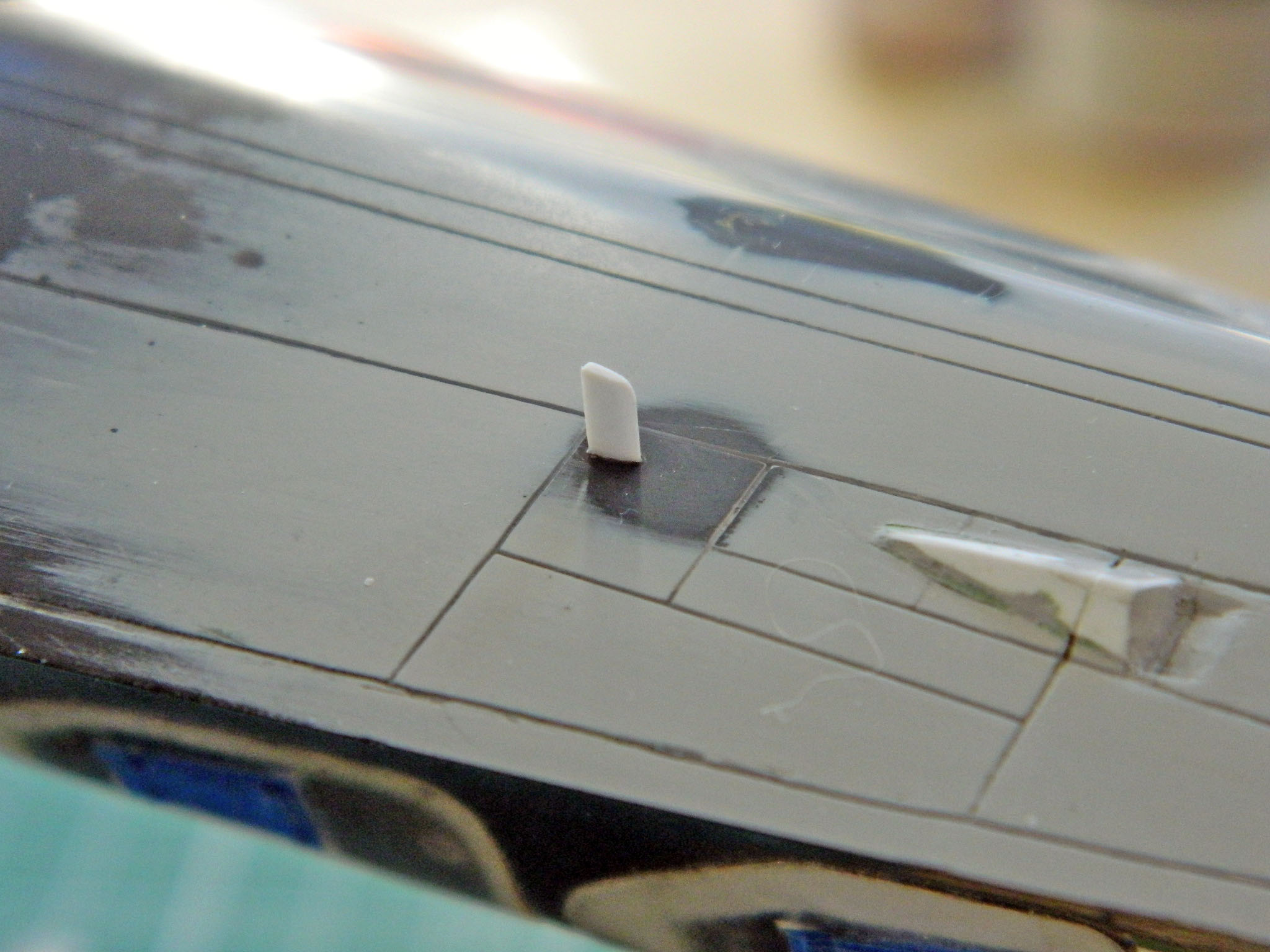
Another small detail was to add a fin-shaped antenna under the port nose (or left, if I’m not trying to impress):
Since I’d done so much work on the back of the fuselage from so many different colored pieces, a coat of primer showed me the few areas that still needed some attention:


At this point, I realized that all I need to do is to attach the landing gear doors, mask the landing gears, and this thing is ready to paint!
Oh my…this thing is almost done…
