Before the upper hull can be mated to the lower, there are a fair bit of small items that have to be worked and painted:
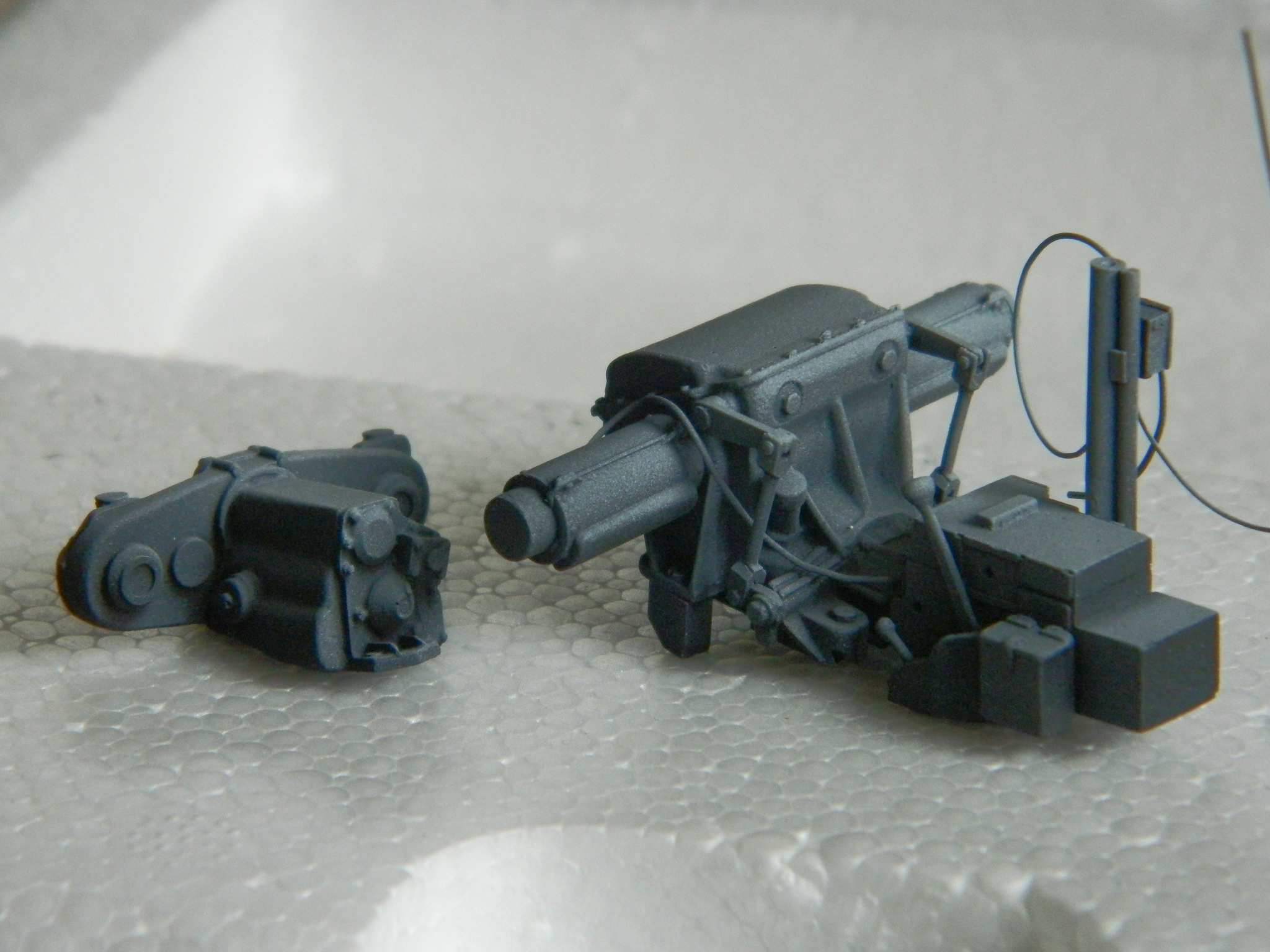
I decided that either I overdid the preshading or I under-did the color coat on the differential/transmission assembly, so I hit that again with white after this photo was taken:
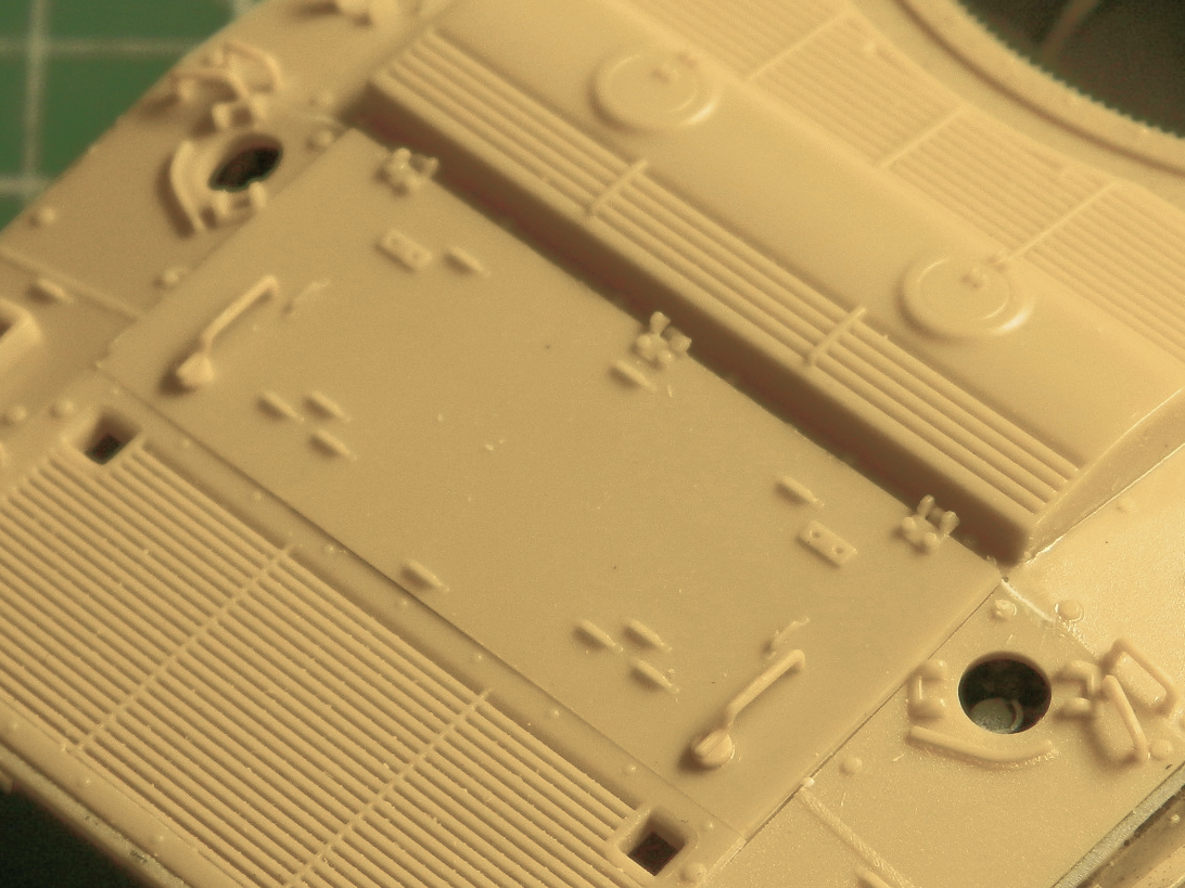
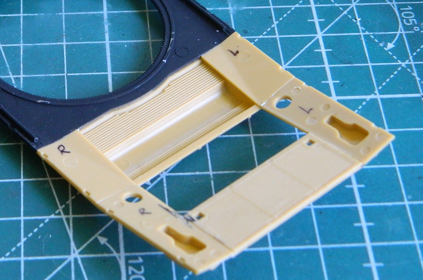
My initial intent was to have all of the upper hull panels be removable. As I tried fitting things together I came to a couple of realizations. The first was I was disappointed with how the parts fit. Good thing I don’t smoke cigars because it was a matter of close but no cigar. The second was that I thought having them removable was too much of a gimmick and that I was just begging for something to break. The more things get handled, the greater the opportunities for things to be damaged. I taped the forward section of the upper hull into place so that I had a reference point to align things as well as they could be, then set about gluing, aligning, and using scrap stock to fill gaps. I started by filling the gaps:
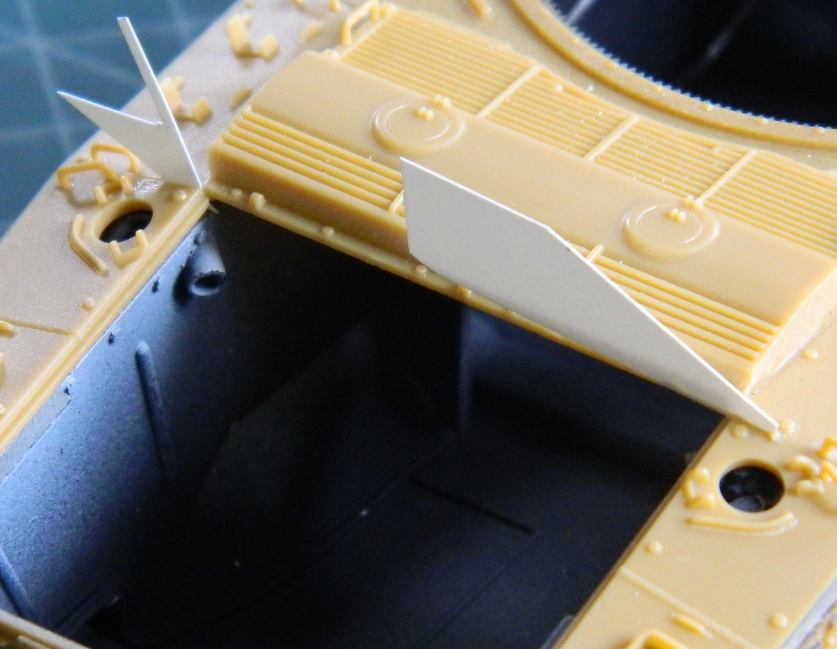
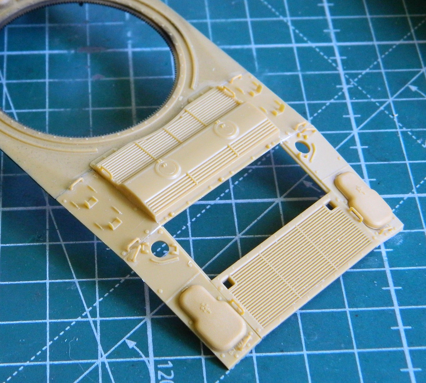
Then making the engine cover fit, which if you look to the left of it you’ll see it doesn’t really:
And done:
The upper hull was set aside to let the glue cure completely:
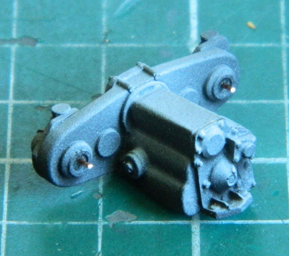
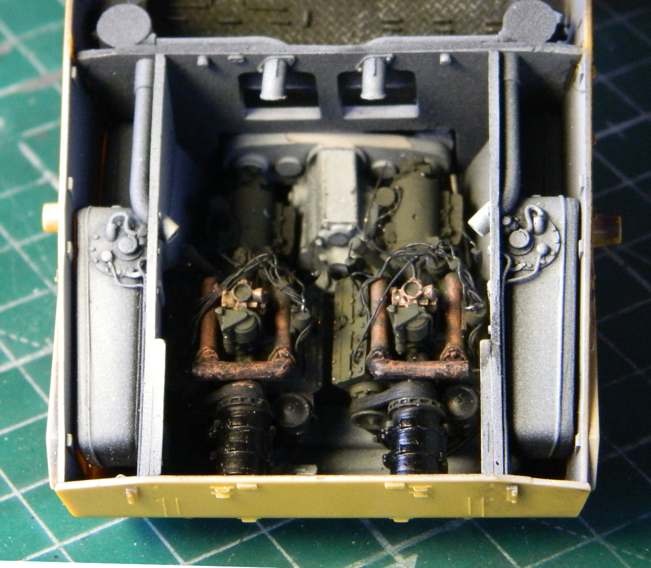
Then it was time to see how well, or not, the engines would fit. I started that by first dry-brushing Italeri’s #4675P Flat Rust onto the exhaust manifolds and pipes, and then touched up the spark plug wires:
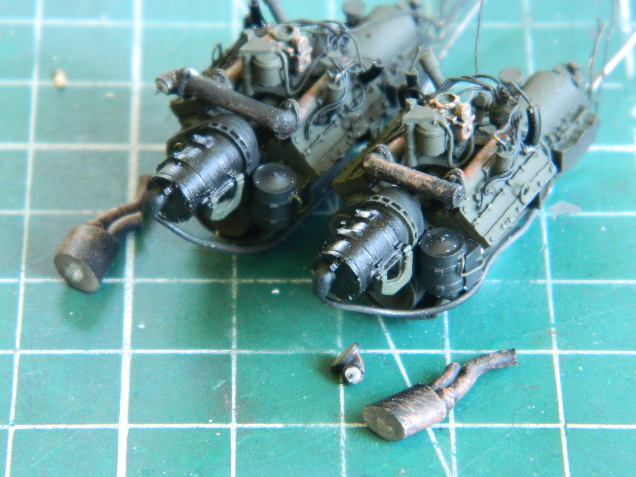
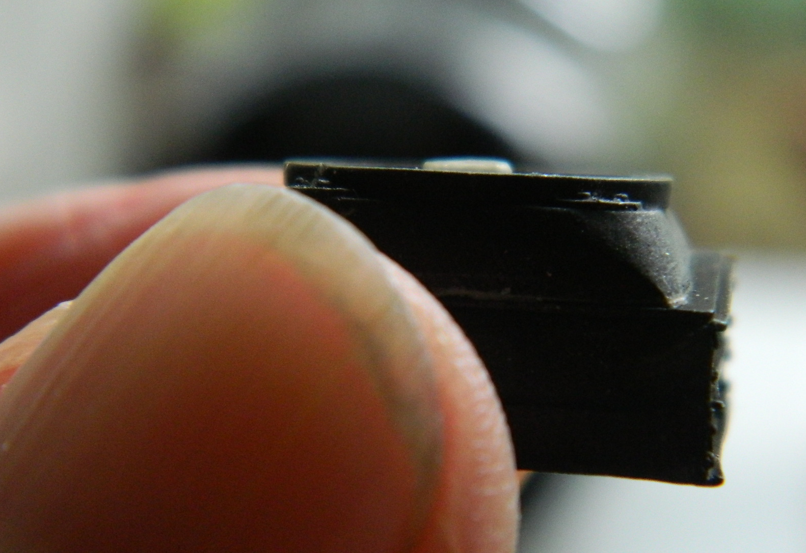
If you look closely at the above photo, you can (barely) see where I added pins to the exhaust parts to make aligning them easier when it comes time to put them together. I also added pins to the transfer case where each engine joins it:
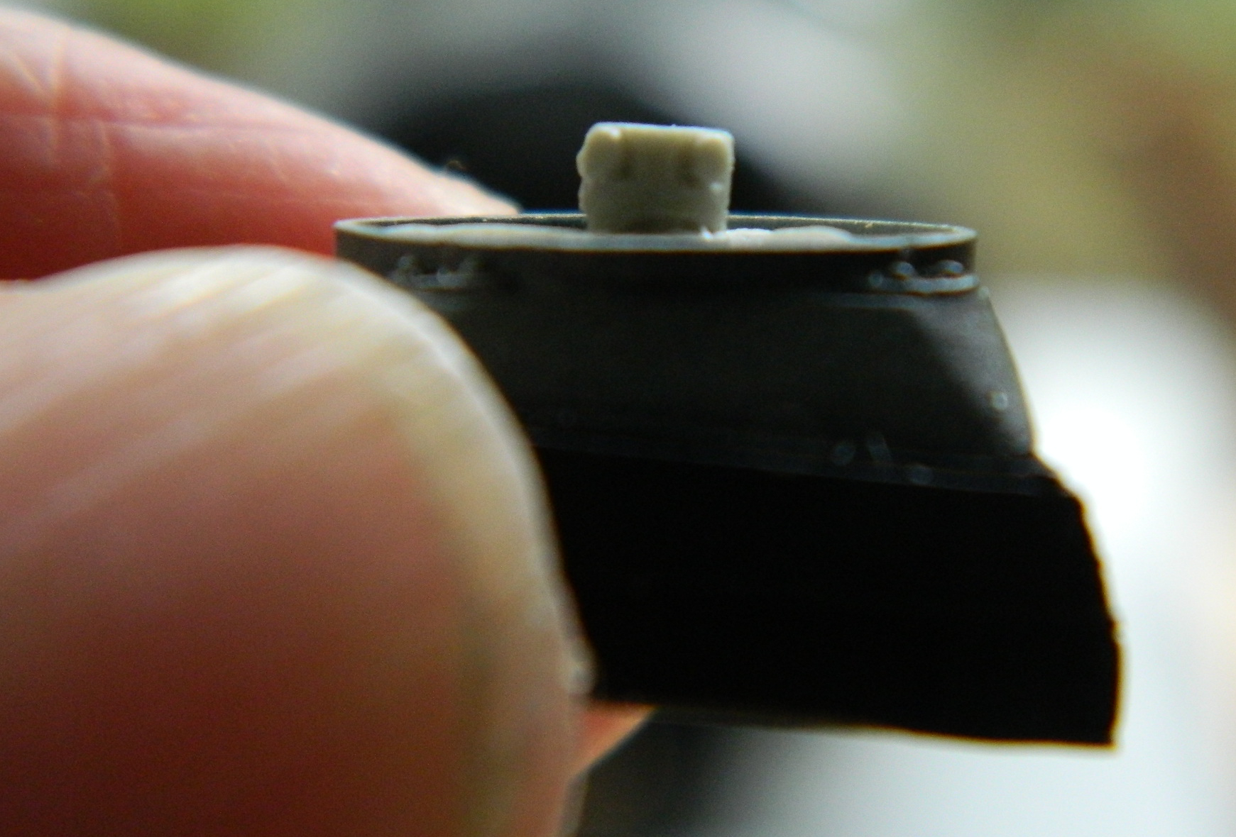
I needed to finish the radiator/fan assemblies as well. Dry-fitting showed that the fans dropped too deeply into the radiator shrouds:
I made spacers from styrene scrap so that the fans would sit at the correct depth and glued them under the fan where they can’t be seen:
I used 18awg solid strand wire for the mounting brackets (and I dry-brushed aluminum onto the radiator faces in case it can be seen…which it cannot, of course):

With the necessary alignments done, the fans were trimmed and their edges thinned, the U-shaped hose manifolds were aligned and glued to the radiators, then they were glued in place. Once the glue had set a bit, things were painted:


Now to see if the engines fit…and no. Not quite. Either the space allotted is just a bit too narrow or my detailing took up more lateral space than existed. I couldn’t get them to sit straight:
There are raised ridges next to the cylinder heads of the engines and I realized I could probably get just enough space to get the engines in place if I removed some of them. I got lucky:
I walked away with the pressure relieved, took the next day off as reward, and came back to realize that yes…they were indeed in straight. And yes…they were indeed too far forward. I walked away for the remainder of the week.
It’s quite vexing to make a mistake like that and not know how it was made. I thought I’d checked fit and alignment along every axis involved. Clearly not and no answer to “why,” meaning at some point I could do it again. Quite vexing.
I had been making a video of this particular step; fitting, aligning, checking (giggles), and gluing. Much gluing. Enough so that as soon as I realized the error, when I tried prying the engines and transfer case free, I don’t know if it was plastic or resin that I heard creak. Regardless, that ended the notion of prying anything out of there. In the process of editing the video, I saw exactly what I did that resulted in a major Brain Fade.
I was having problems getting the transfer case to fit between the gap of the bulkhead on top and the torsion bar housing underneath. Very early on in the fitting and head scratching phase, unnoticed by Yours Truly, I reversed the transfer case. I certainly did get it to fit nicely, though, I just did it with the part backwards. Then when I added the engines to the mix, I had to put the transfer case in correctly due to the engines and pins needing to meet. That meant the transfer case wasn’t fit correctly, it was too far forward. Attach the engines to it and they were also too far forward.
The angels didn’t exactly sing, but there was much melodic giggling heard from On High when I finally realized how the mistake happened.
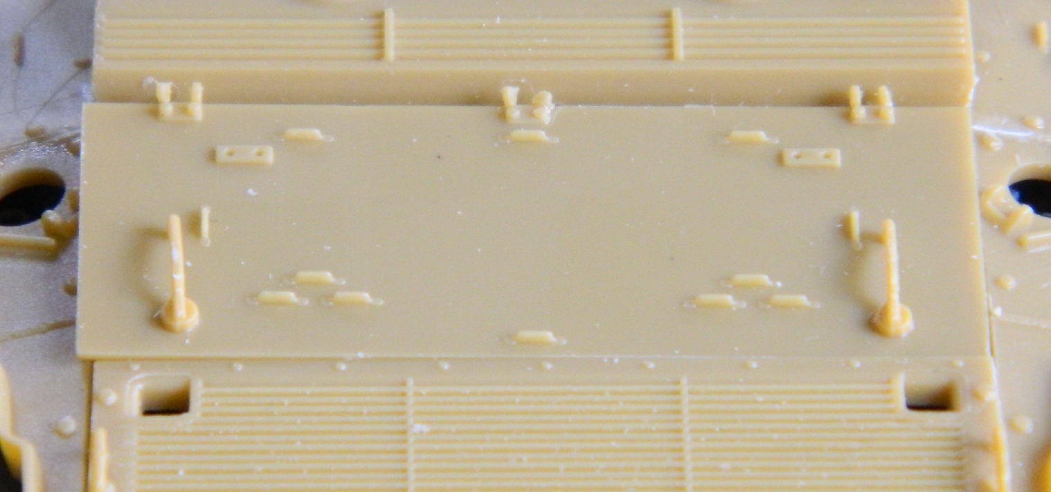
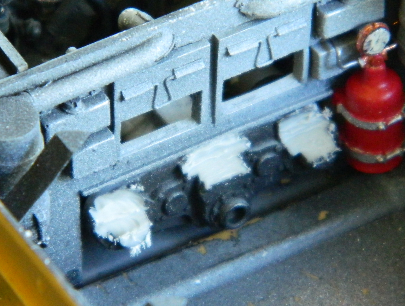
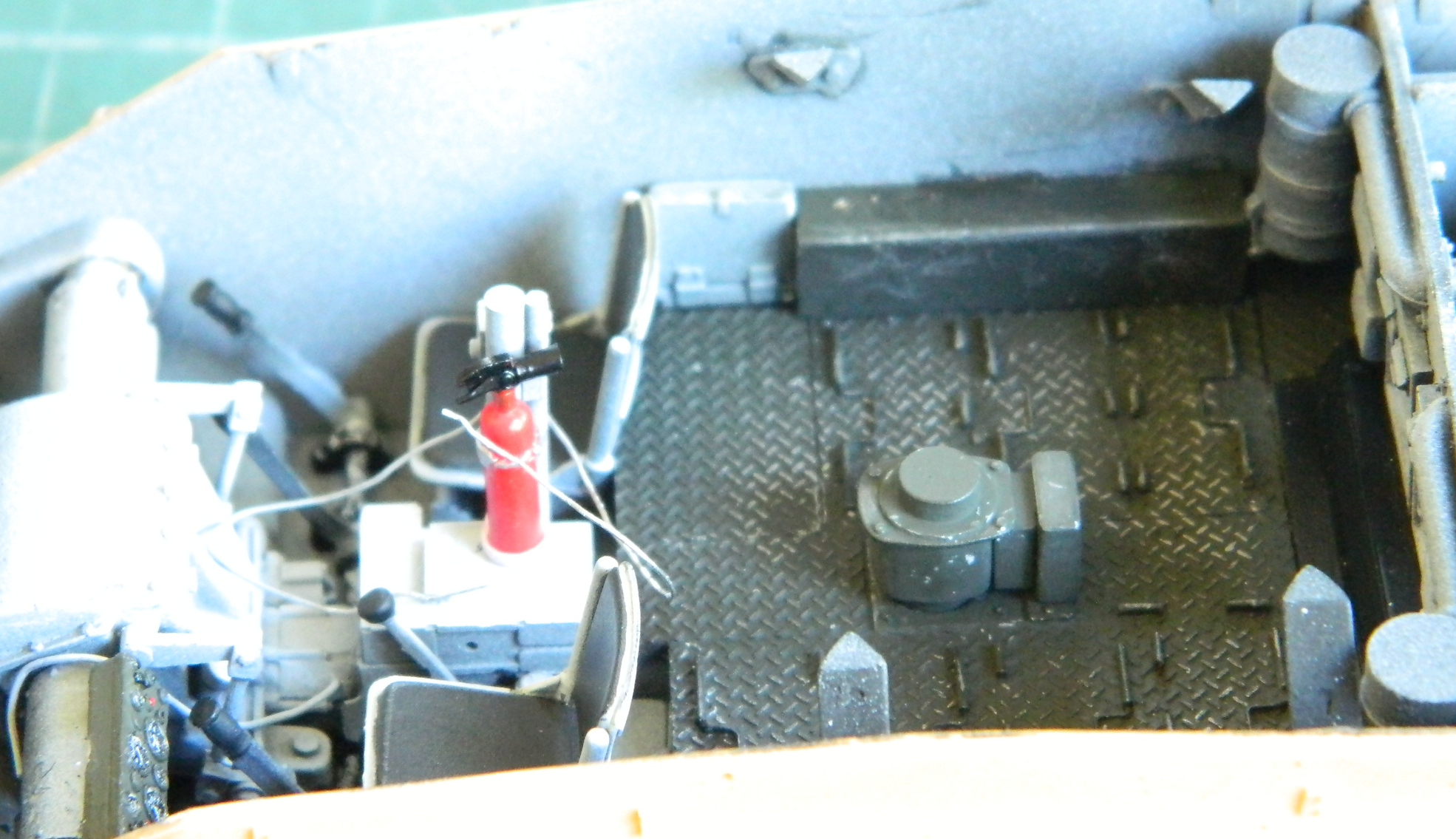
The first domino after that mistake was the fit of the floor inside the crew compartment. The forward end of the transfer case extends into the crew compartment and has a raised section of the floor to accommodate that. With the transfer case in its new position, it didn’t allow the floor to set down where it should. It’s not blatant, but if you look at the semi-gloss black ledge that extends from the rear of the diamond tread floor, it isn’t parallel with the openings and boxes of the bulkhead as it should be:

Not thrilling but neither unexpected nor insurmountable. The solution is to simply grind away however much of the transfer case I need to in order for the floor to settle into place. The areas removed will be never be seen again after the floor is glued in:
Once the resin in the three locations had been ground away sufficiently, the floor was glued down.
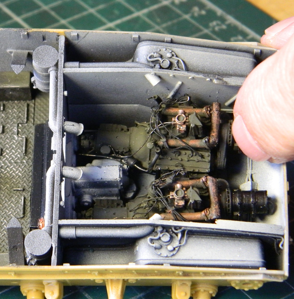
With the engines in place (permanently) I was able to install the radiators. The two lower support arms for the fans were dry-brushed black to blend in with the pre-shaded engine bay:
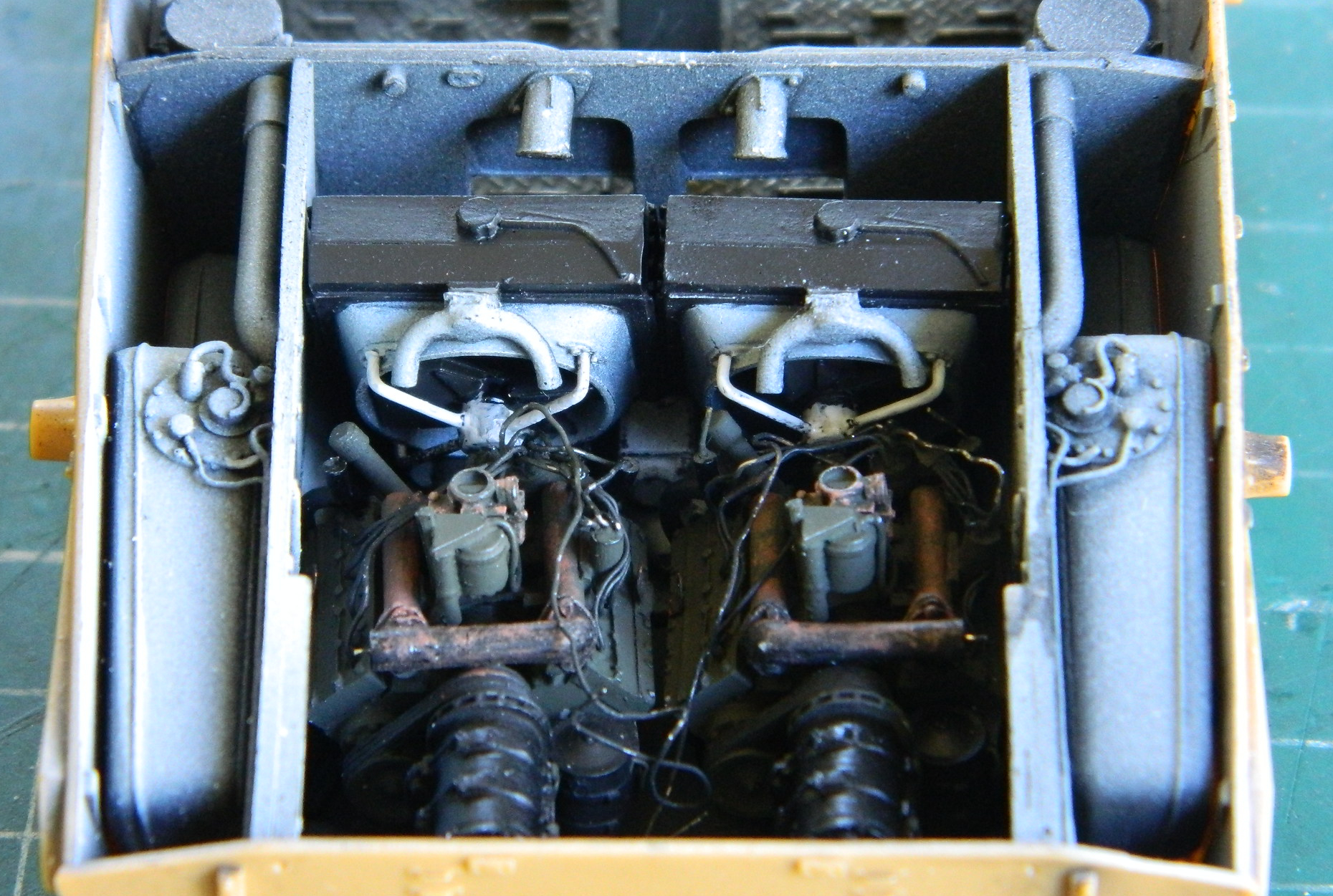
With the upper hull in place, not much will be directly seen (and is why I didn’t add the oil cooler radiator). What can be seen is as correct as 90-95% allows for:
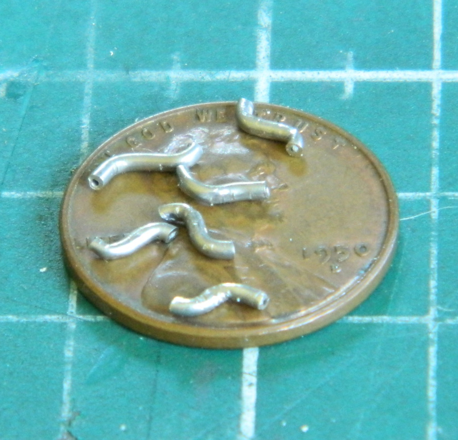
Next I had to connect the hose attachments on the radiators (the inverted U-shape at the top of the radiators) to the attachments on the coolant manifolds. Once again, solder came to my rescue. I used .062″ (1.57mm) solder to fabricate the “hoses”:

Sometimes one must persevere. None of it happened the first time:
A quick coat of Tamiya XF-85 Rubber Black and the “hoses” settle in visually:

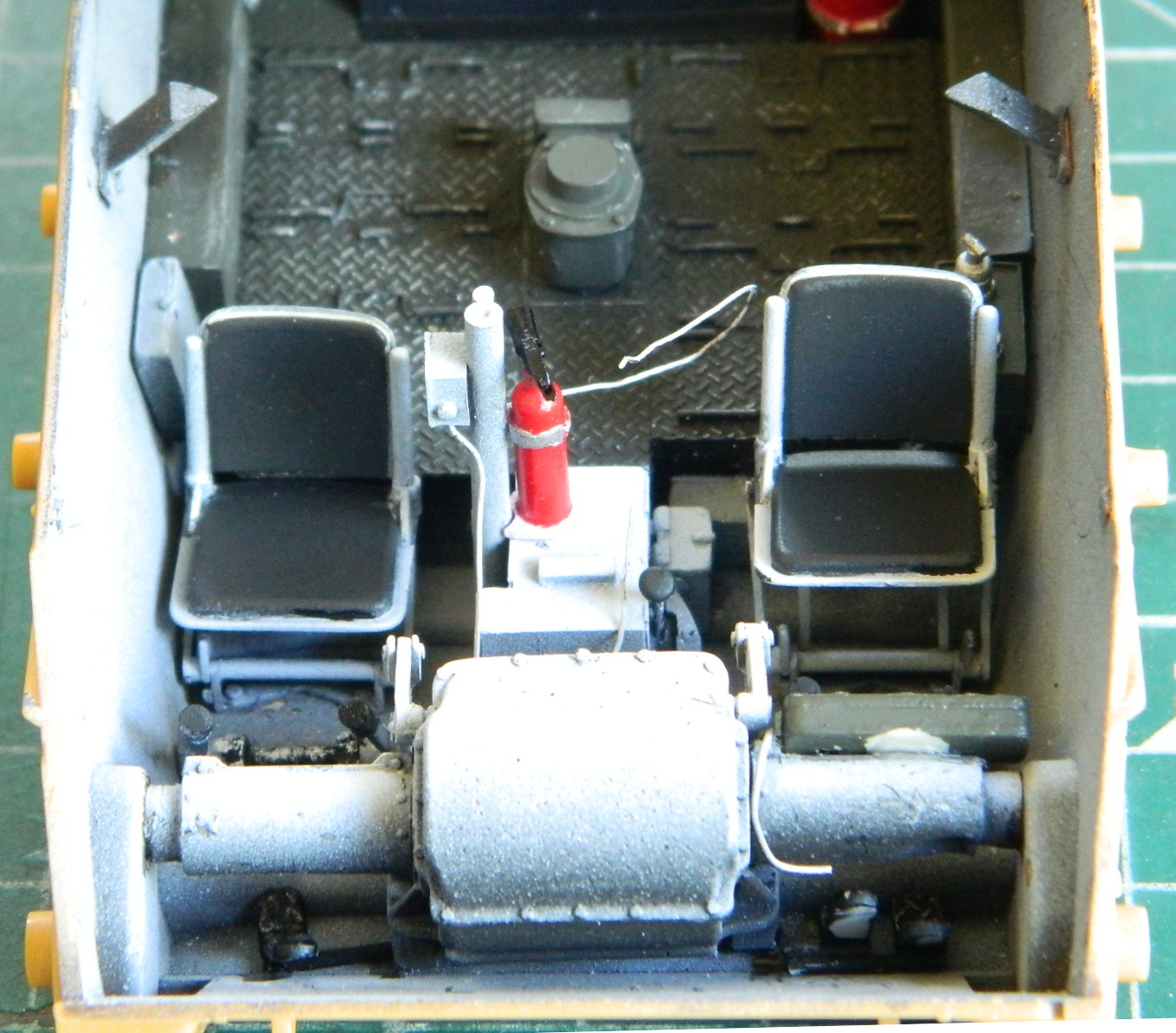
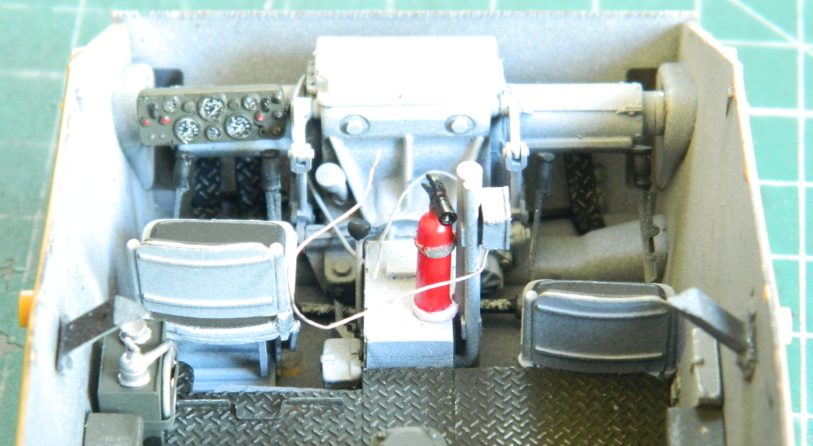
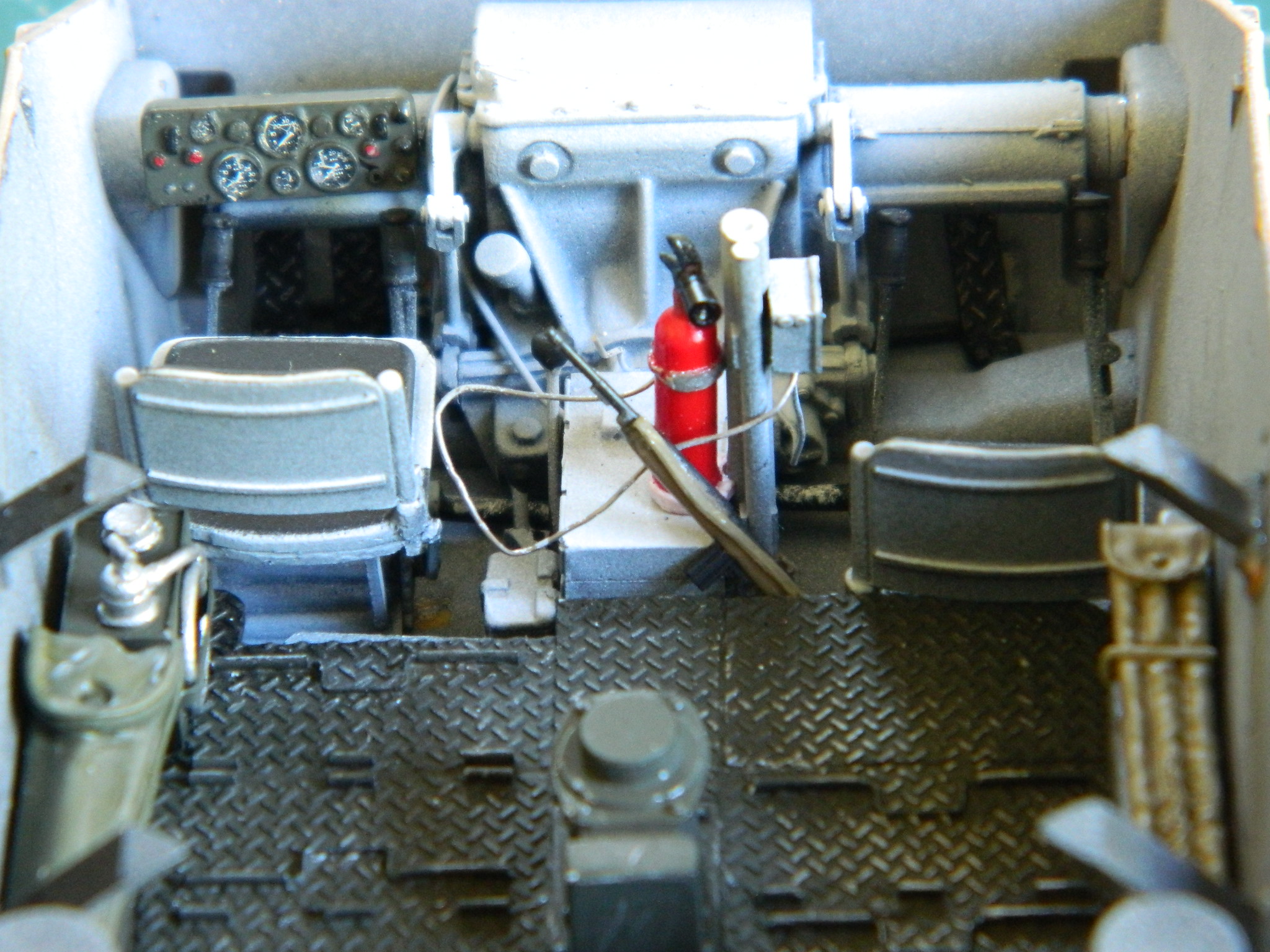
With the floor glued in place, it was time to begin populating the crew area. Seats, pedals, control levers, seats, oil can, and fire extinguisher were glued in, not to mention the differential/transmission:

Then the list of what needs to be worked, made, and painted starts to grow. There are many things all competing for limited space inside a tank. One of the complaints about the M24 was a lack of stowage space and a small ammunition load. I needed to make racks to stow cans of .30 caliber (7.62mm) machine gun ammo. 0.015″ (.381mm) sheet and 0.010″ (.254mm) brass sheet made the brackets, the ammo cans came from spare parts:

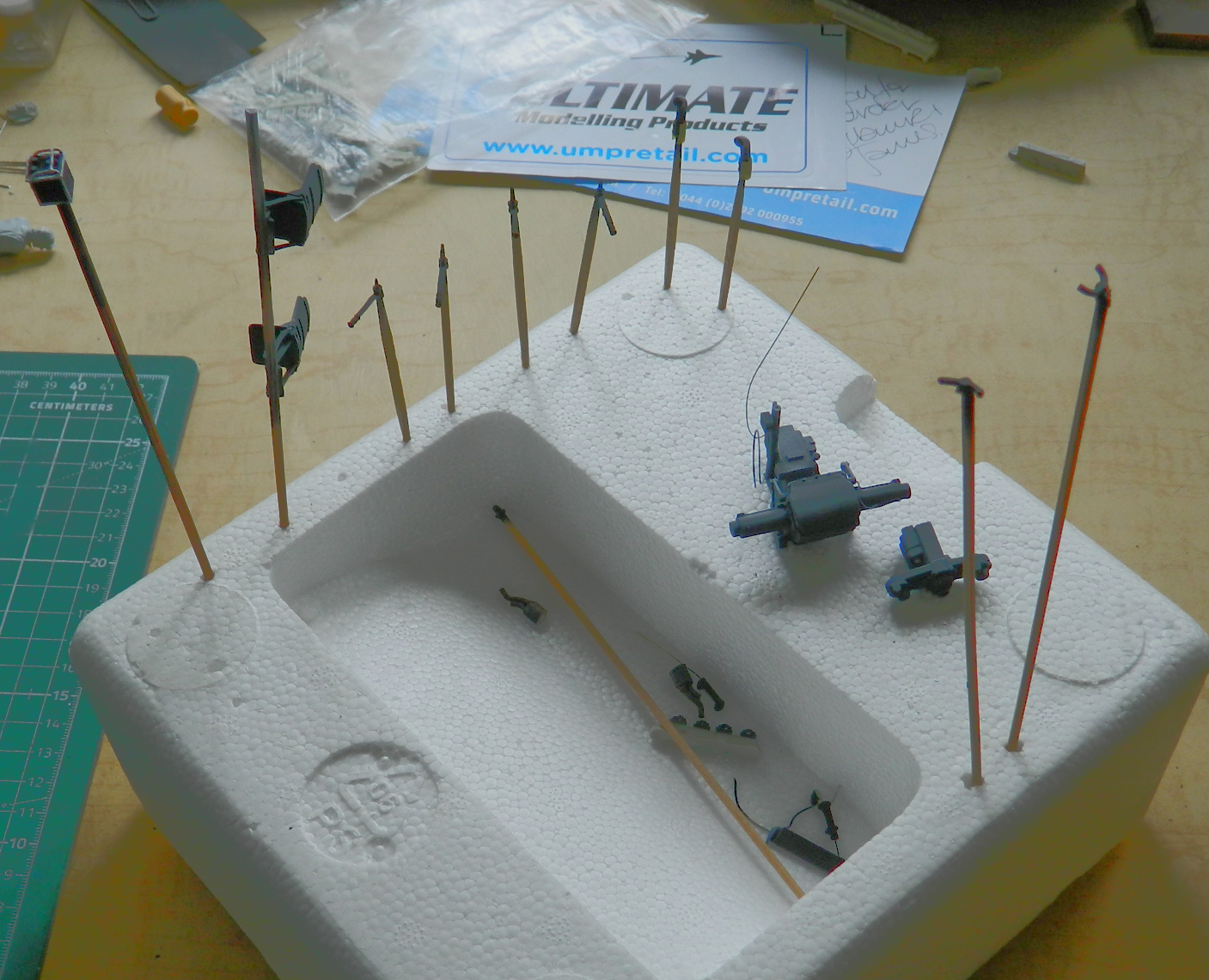
With the exception of the helmet and binoculars that I decided to not use, here’s what has to go either inside the tank or tied to the outside grouped by the paint color(s) they get shot with:
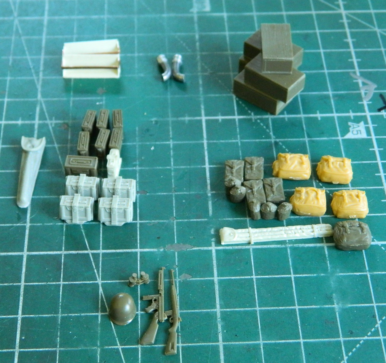
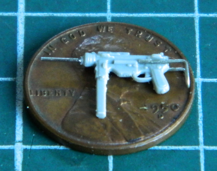
Bronco provides figures and their gear for the kit. I’m using Bronco’s M3 “grease gun” submachine gun (for the driver) and Tamiya’s M1A1 Thompson (stashed in the turret) and M1 carbine (for the co-driver) (and couldn’t the Army call their hardware something other than M1?!).
The M3’s barrel and sliding stock were plastic and definitely out-of-scale. Instead I used a hypodermic needle for the barrel and 24 gauge wire for the stock (Tamiya’s small arms were fine to use as-is):
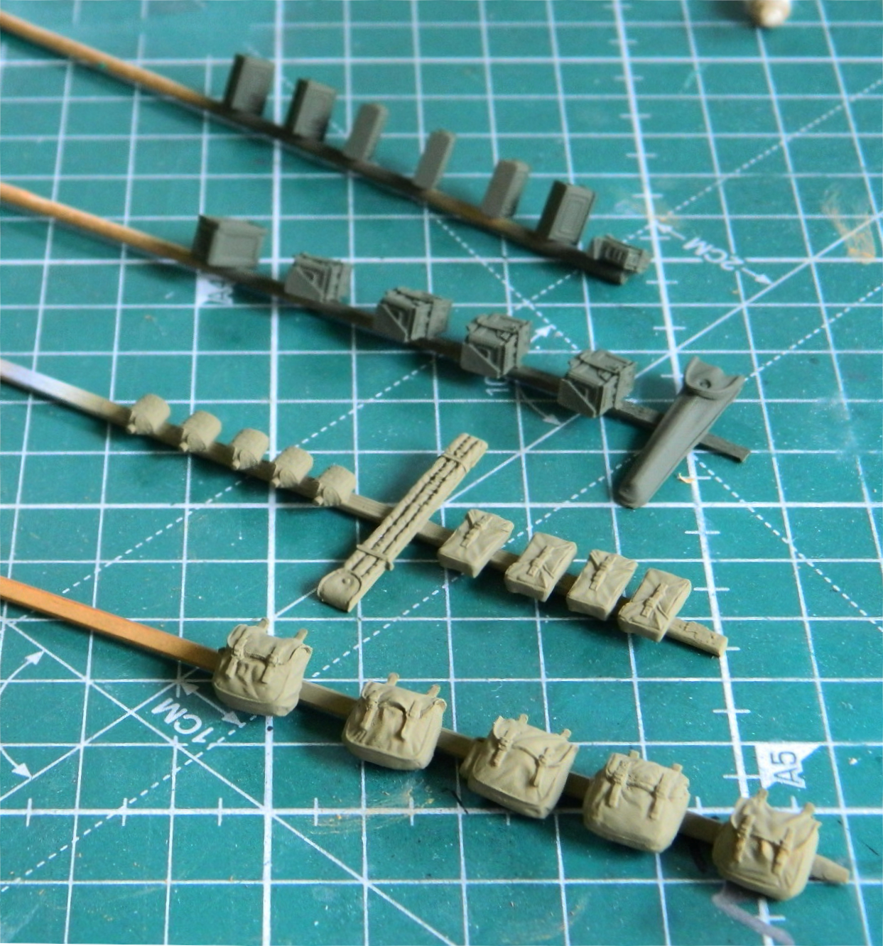
One of the things I wanted to do was to fill the hollow backs for the rucks and pouches. I used Apoxie Sculpt as filler:

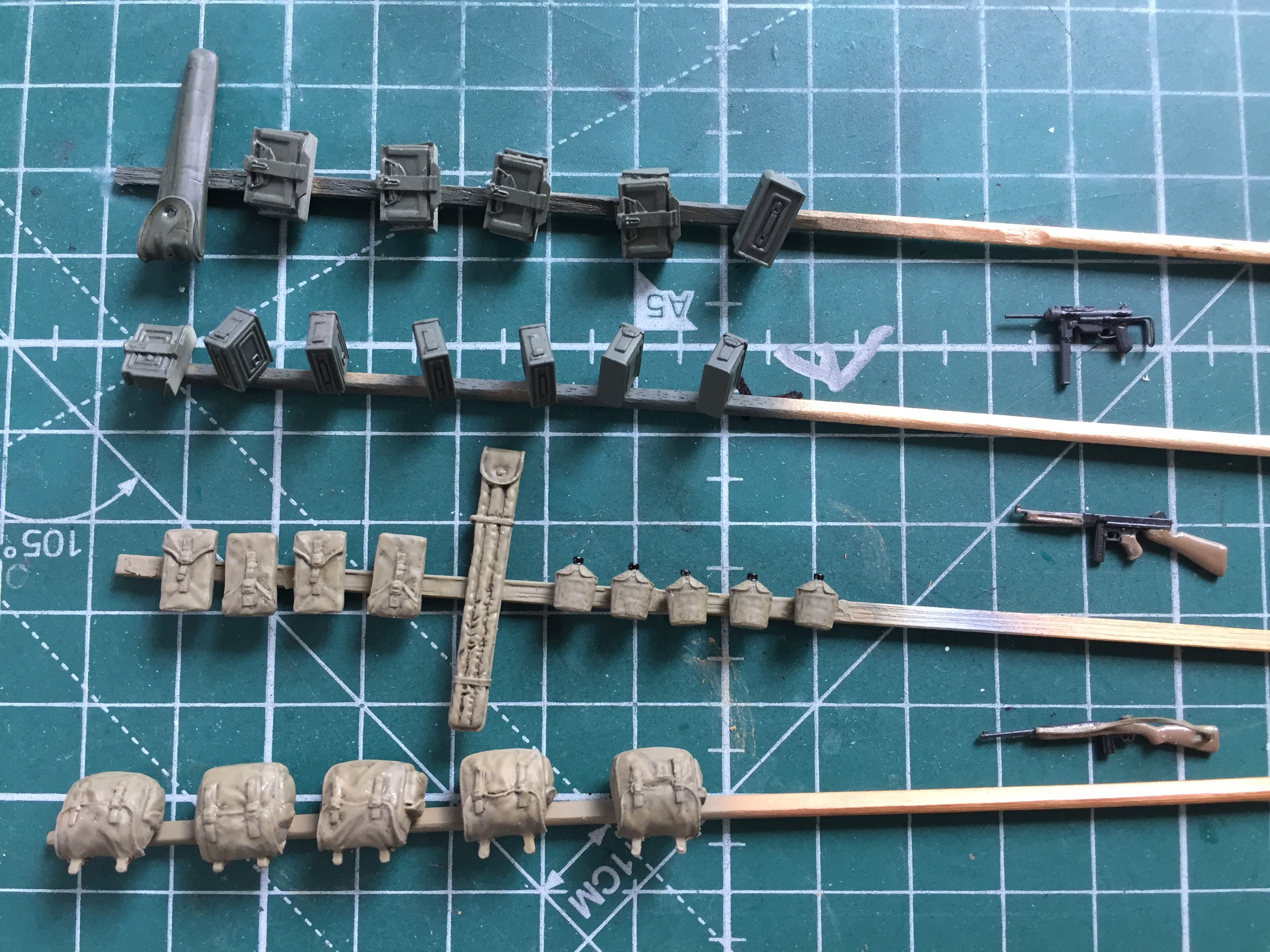
I let the putty cure overnight before refining its shape and making it look like the rest of the item. The small parts were glued (small dab of superglue) to bamboo skewers and the base colors were put down. Tamiya Olive Drab (XF-62) for ammo cans and the spare .50 caliber (12.7mm) barrel bag, and Tamiya XF-49 Khaki for cloth items:
After sitting overnight, I hit them with Tamiya X-22 Clear Gloss and let them sit overnight again. I used Testor’s Gloss Black for a wash and hit all items before the last coat of Tamiya XF-86 Flat Clear finished it:
Generic dirt/grime/wear will be added with pastels.
The small arms were painted with five parts Tamiya X-18 Semi Gloss Black and four parts Tamiya XF-20 Medium Gray where metal would be exposed (The M3, not having wood parts, is all that color). The wood parts were painted with Heller Natural Wood (sorry, no part number). Heller Natural Wood does NOT mix well using denatured alcohol as a thinner…unless you want something that looks like wood-colored cottage cheese. The sling for the carbine is lead foil painted with Tamiya XF-49 Khaki:

There are (and will be in the model) brackets to hold the crew’s small arms. As they were probably issued M3s, the co-driver having an M1 means it won’t fit in the M3 brackets. Were I sitting in the right seat, I’d want my piece close to hand but where it wouldn’t get in the way of moving hardware (in this case, leaning to the left of the seat):
From here, what drives the build is what I have to do next to be able to put the upper hull on permanently. And speaking of that…here comes the next domino.
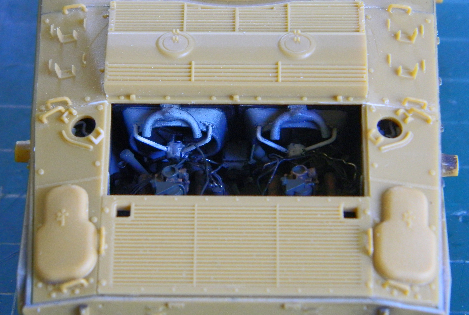
With the engines sitting too far forward because of the transfer case error, that means the radiators should be sitting too far forward also; the location of the engines dictates the placement of the radiators. It was with no small sense of trepidation that I put the upper hull in place. There is a raised area over where the radiators should be and I wasn’t sure how badly the misalignment of the radiators would be or how that would affect the upper hull placement.
There wasn’t any misalignment of the radiators! What I lack in quickness I like to think I make up for with thoroughness (but then, we all have our illusions). I made sure the upper hull was where it has to be. I checked quite closely to see where the raised area lined up. I even walked away for a couple of days before checking it again with fresher eyes.
Nope. No misalignment. Falls WELL within the 90-95%.
That leaves me with the conclusion that where I had intended to put the engines was inaccurate. Serendipity saved me much vexation by having my “mistake” counter my impending MISTAKE.
Just about the time I’m arrogant enough to suspect I know what I’m doing, something like this happens. So no…I’m not being humble when someone tells me how good I am at this and I demure. I’m not humble.
I’m experienced.
