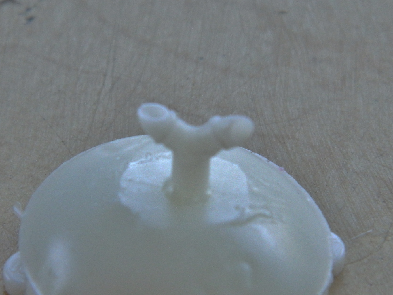
There was one thing I wasn’t pleased with when I made the initial master for the vent/blower assembly and that was the vent ducts. While I was making resin copies, I looked at the sacrificial casting and thought that those vent ducts were about the right size. I cut the ducts from the casting, shaped them to fit each other, and glued them together:
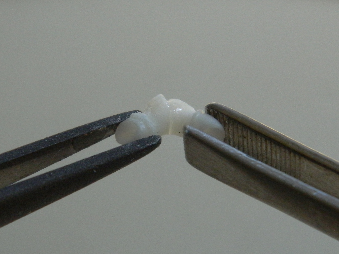

I checked them against the blower and liked what I saw. And then I noticed something I hadn’t before and that was freakin’ bubbles. If you look closely at the photo, you can see the damned things. I checked the filler putty on a piece of this resin to see if it would adhere to it (because it doesn’t always, depending on the resins’ formulation and resultant physical properties), and it does. So if these bubbles are evident I can fill them with putty:
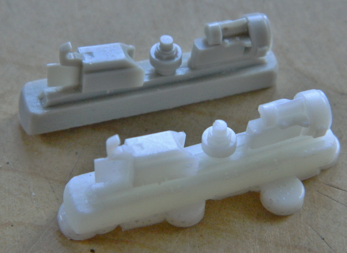
Still spitting and cursing about the freakin’ bubbles, I attached the ducting to the resin pouring cup that resulted from casting the blower and then started building mold boxes. The other items I’m going to mold are experiments to see how complex a shape I can mold and recreate:

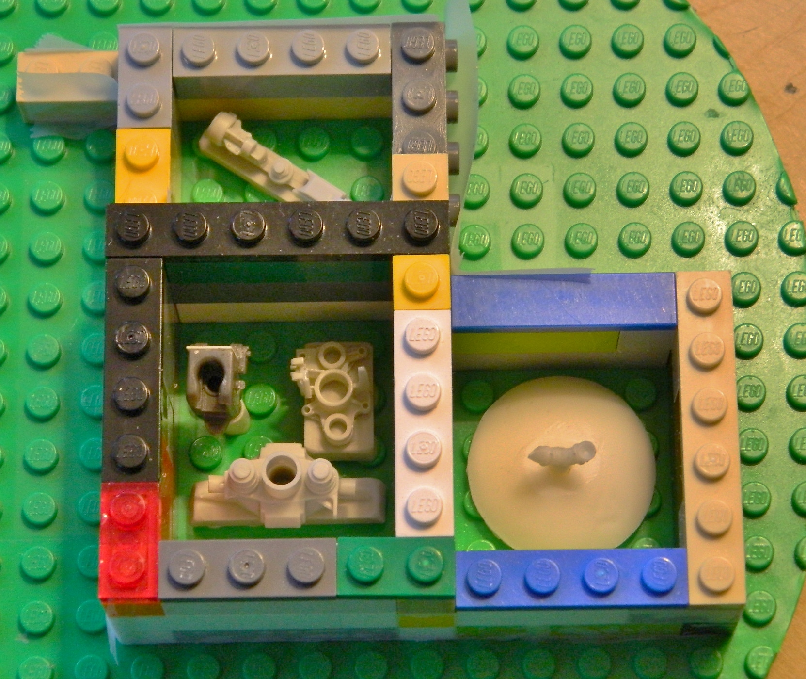
As before, I mixed the molding compound, degassed it, poured it into the molding boxes, and degassed it again. Then I waited overnight for the rubber to cure:
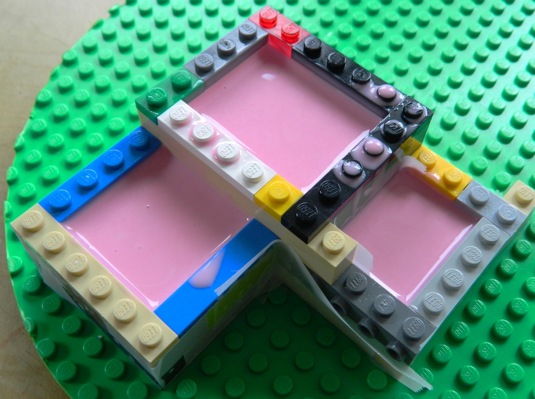
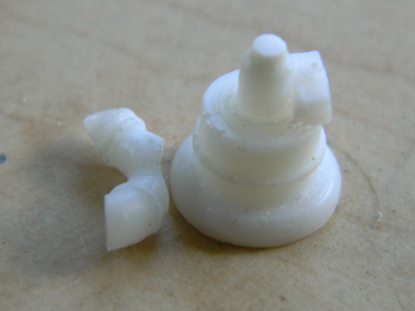
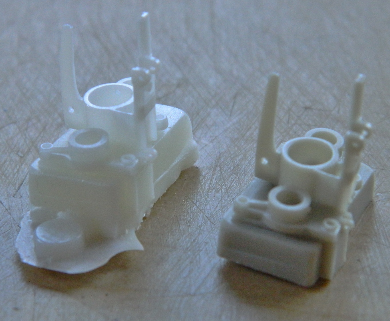
Once I’d separated the molds to get at the castings, I not only ended up with usable ducts, I saw that I can copy fairly complicated and delicate sections with the rubber/resin I’m using (and yeah, more bubbles; if I’m getting this many bubbles in my castings, I’d rather not imagine how many of the freakin’ things I’d be getting if I didn’t have a degassing capability):
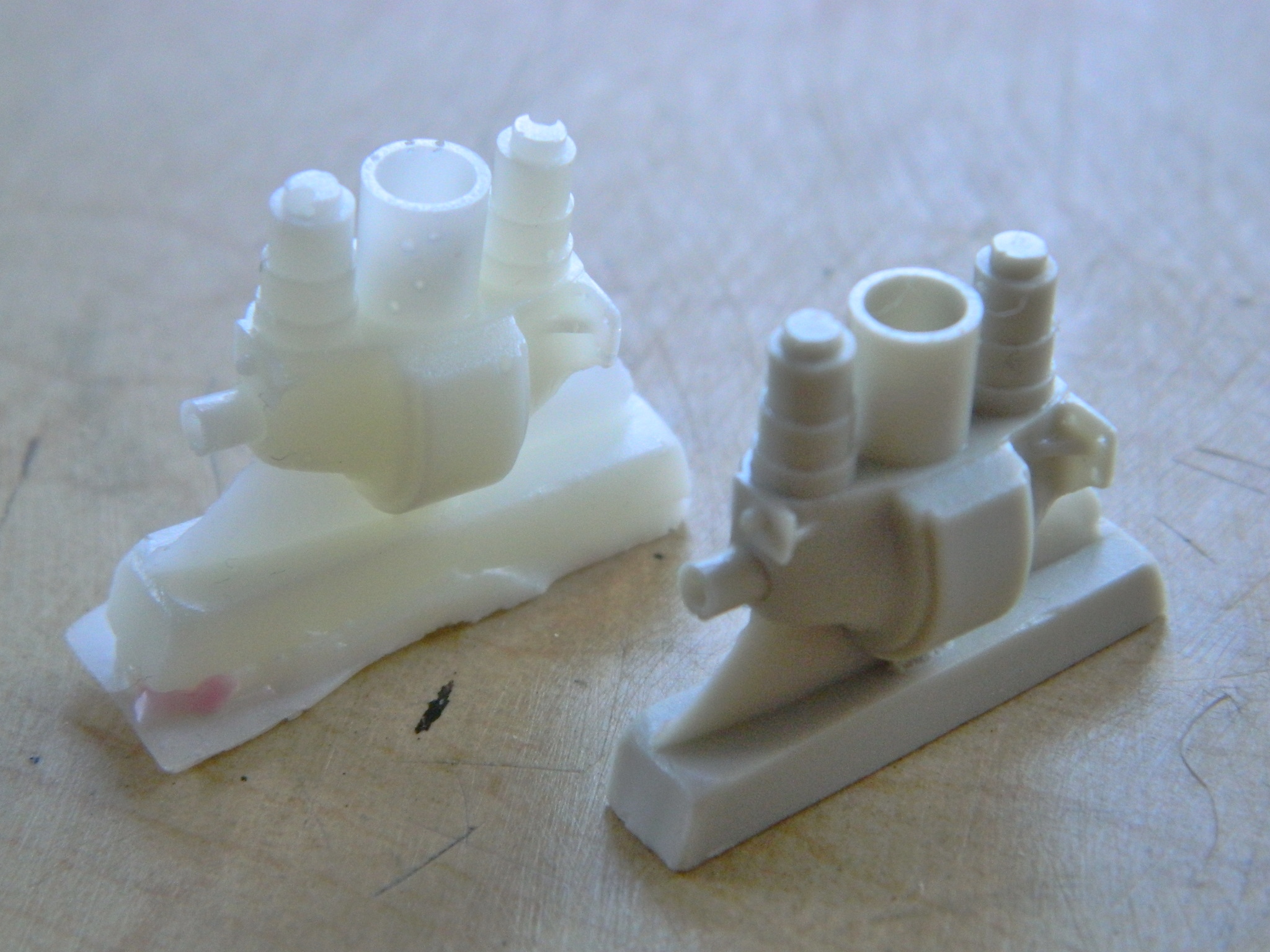
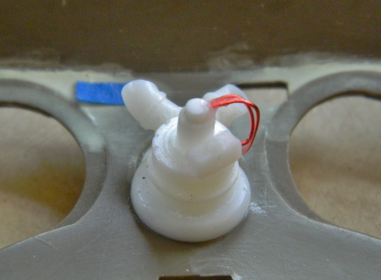
I cut the pouring cup and stub from the ducts, added the ducts to the blower, wired the assembly, and glued it into place in the upper hull:

The inside of the upper hull was now ready to paint. I hit it with a coat of gloss white to prepare it for a dark wash:

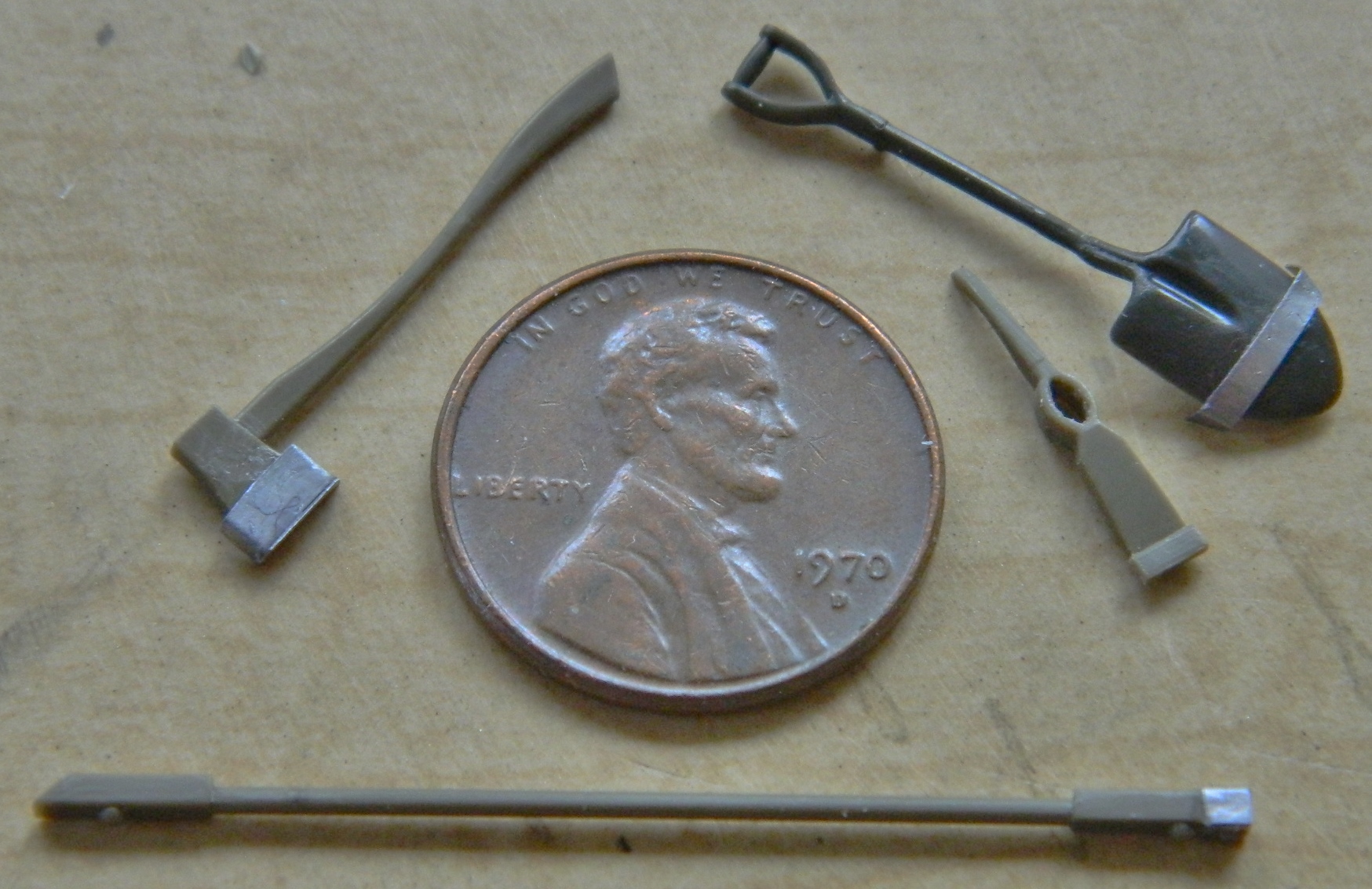
The upper hull has a number of items that get attached to it. Some of those items are what are termed “pioneer” tools and some of them are tools needed to maintain the tracks (change out track links and tension tracks). The pioneer tools are used to dig the tank into a prepared and protected position (can you imagine the work required to dig a hole big enough for a tank to sit in with only its turret exposed?!), or to dig it out if it gets stuck somewhere (can you imagine the work required to dig out a stuck tank?!). I had briefly considered getting a set of AM tools (better detail) but instead opted to see if I could detail the kit parts sufficiently.
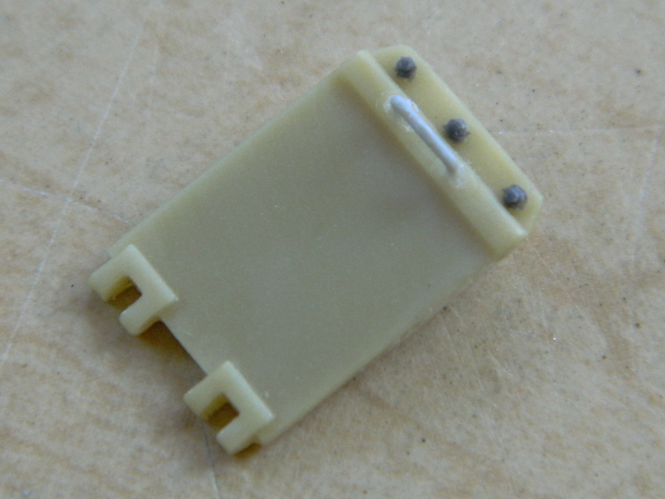
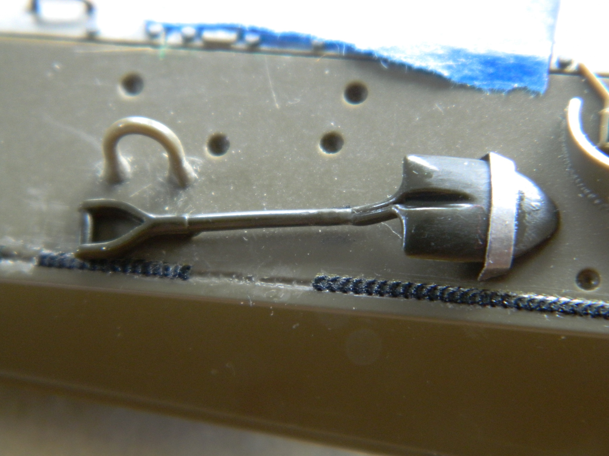
The retaining strap for the shovel is sheet metal, but the kit part has this area molded as a block, so I thinned it out:
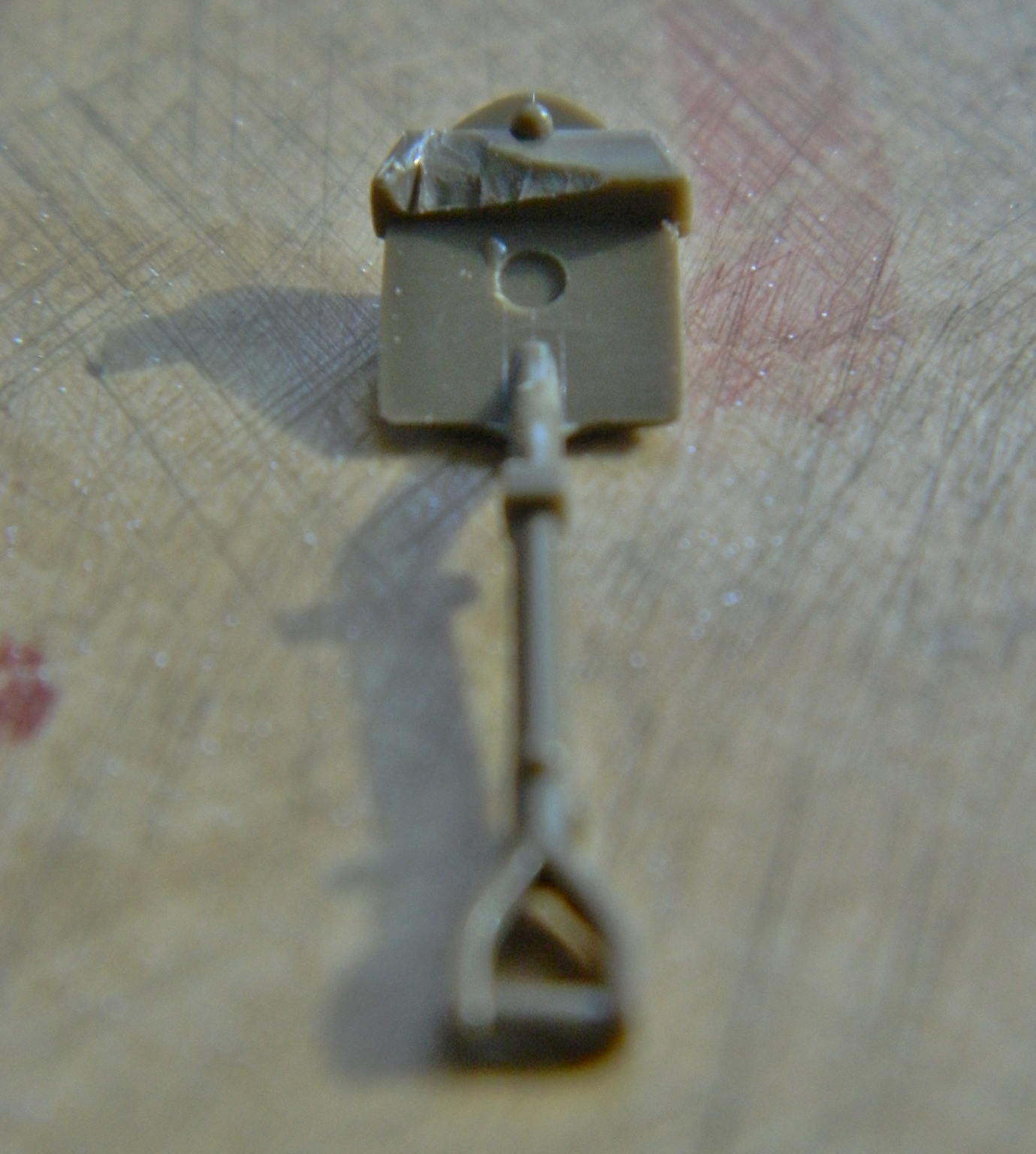
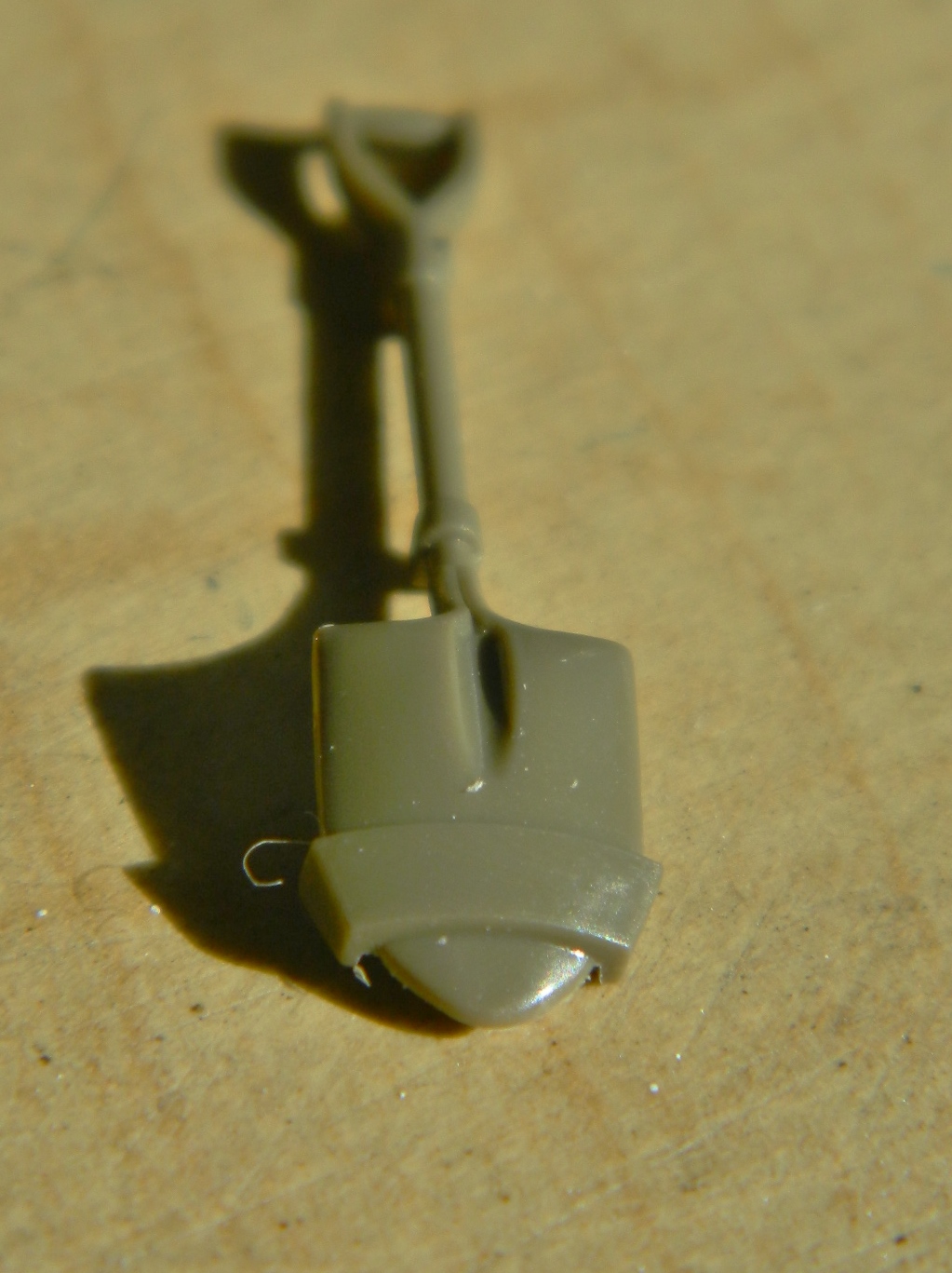

Detailing and cleaning up tiny parts takes a long time. During that time, my brain started thinking about what I was doing (always a novelty for me and I have the scars to prove it). Maybe I would get better results if I removed the molded on strap entirely and replaced it with lead foil, so I tried it and liked what I saw (and in the picture on the right, you can see where the delicate resin weld beads lifted off…not the only place this happened):
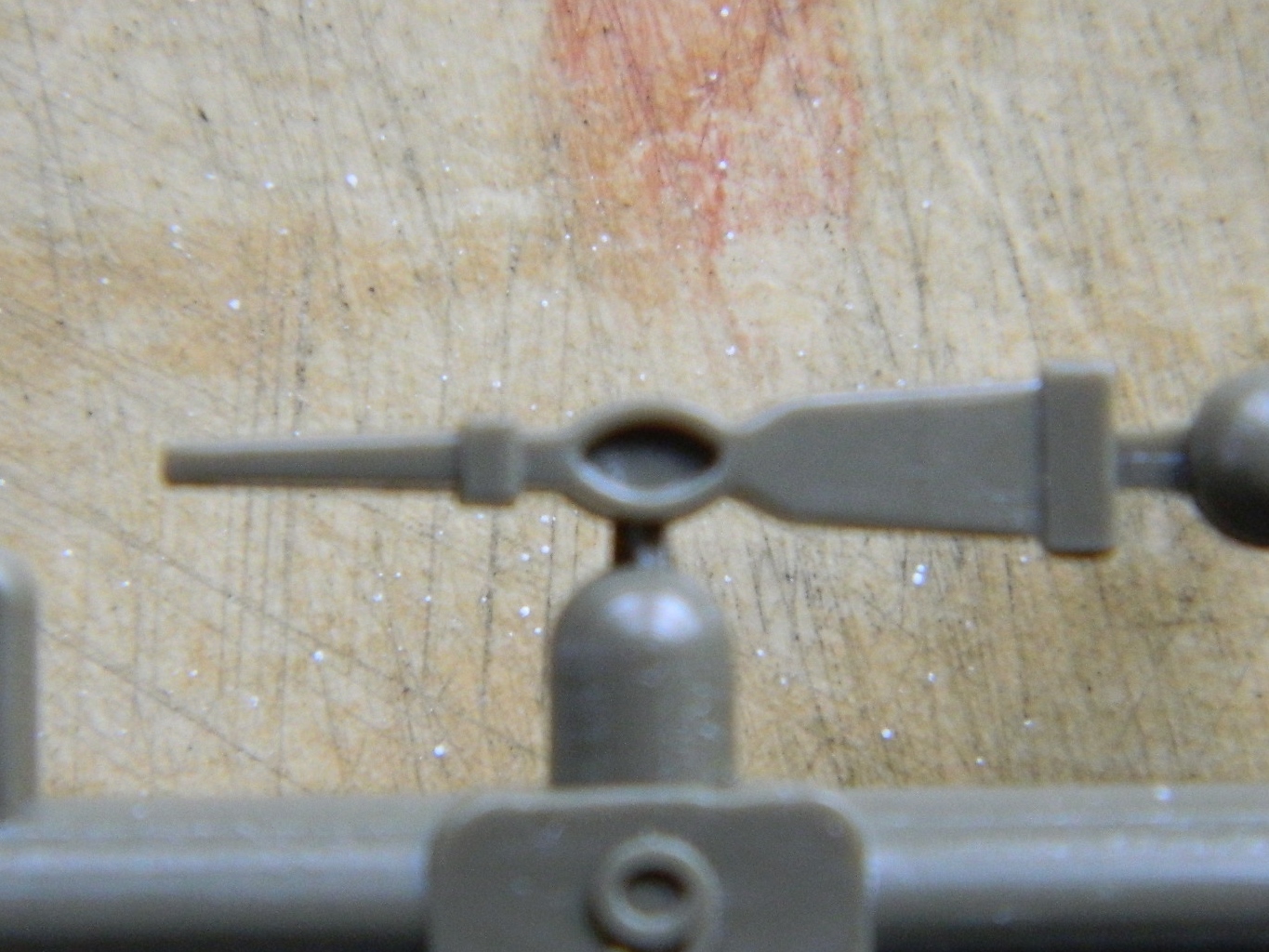
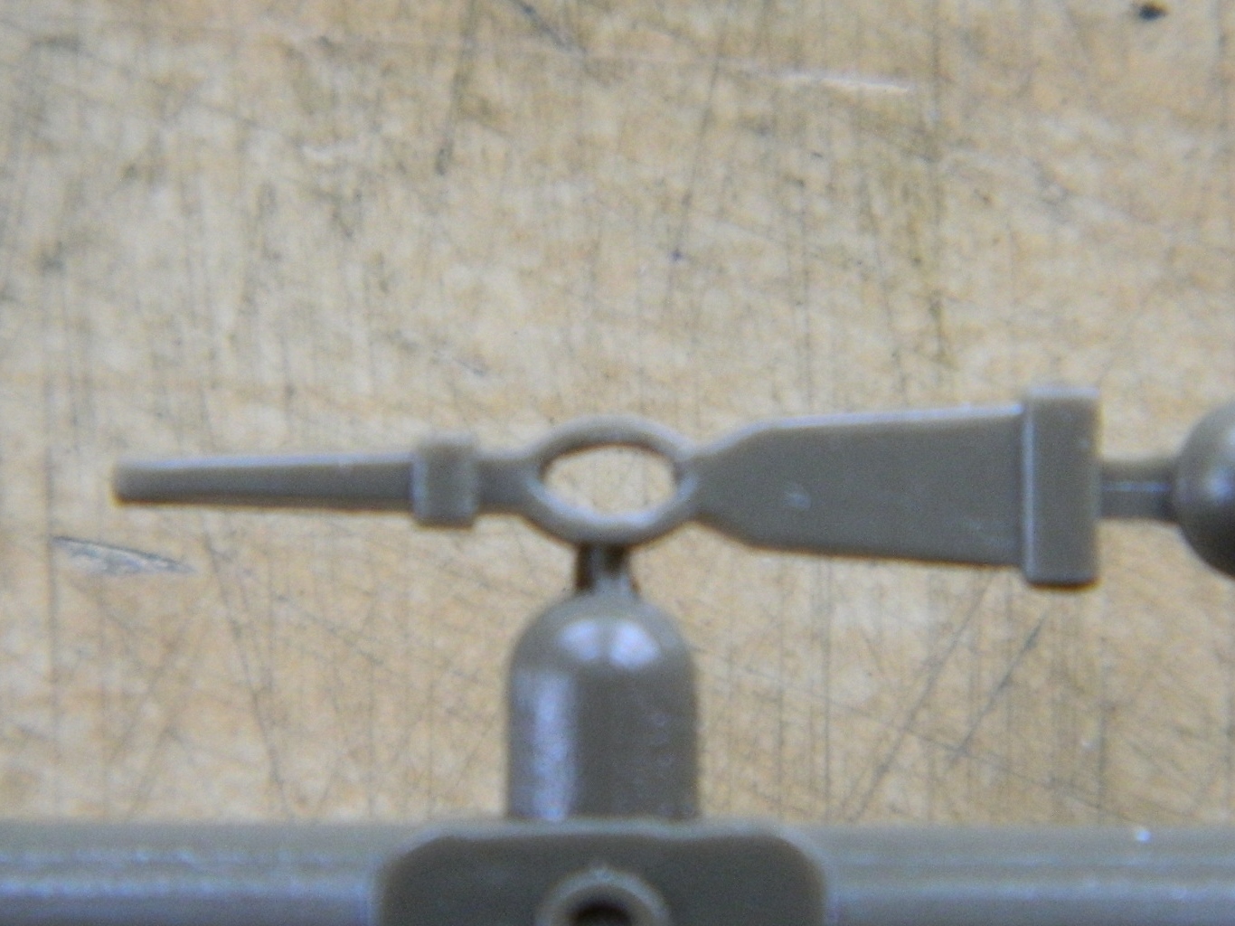
I’ve used a pickaxe a few times over the years. One of the things I’ve noticed about the head of a pickaxe is that there’s a hole where the handle slides through (if that hole isn’t there, the handle doesn’t slide through, and the pickaxe becomes a cast steel version of a rock; not the most efficient way to use a pickaxe, methinks). While the part was still on the sprue, I drilled out the center and carved away what needed to be gone:
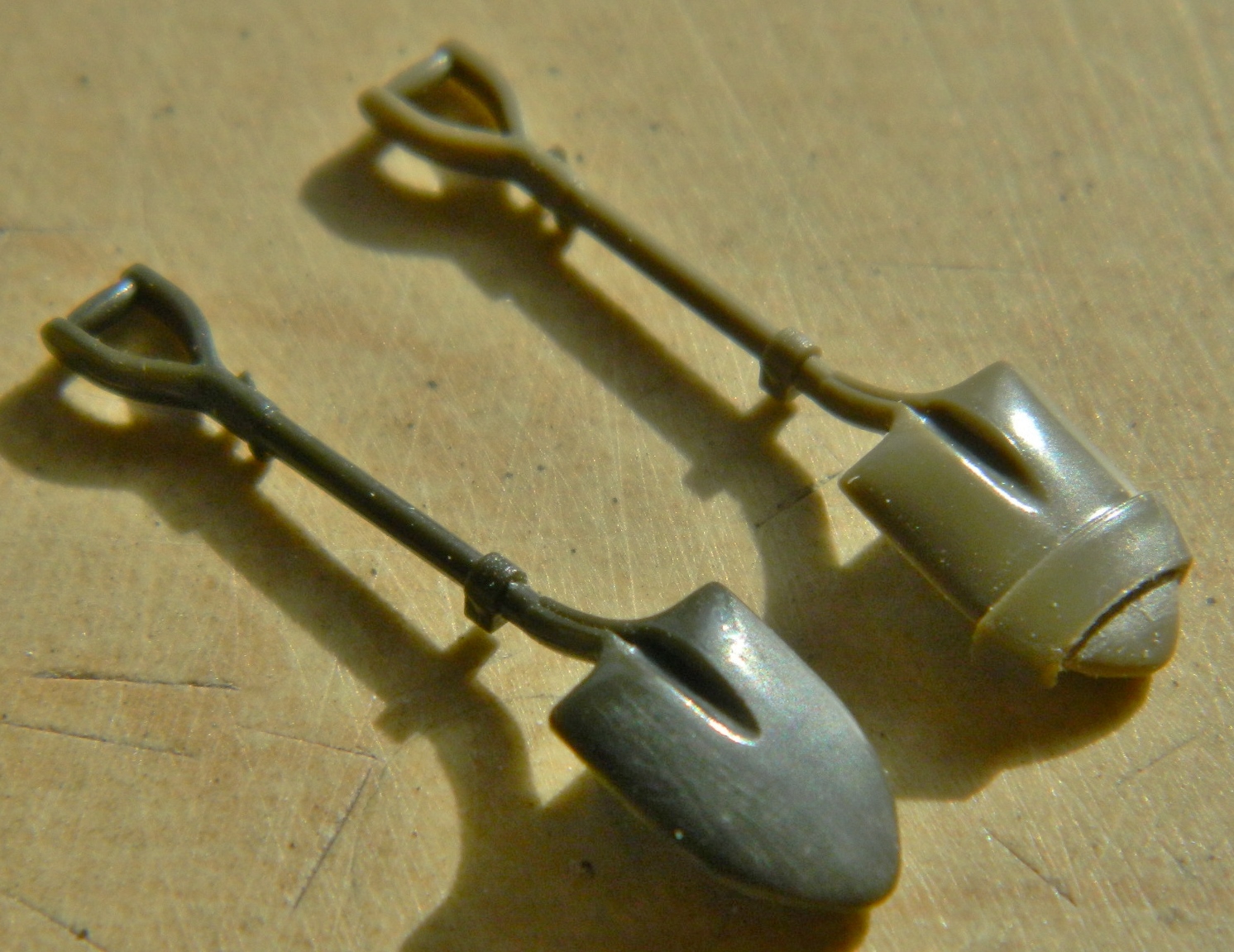
I liked the usage of the lead foil enough to use it on other tools:
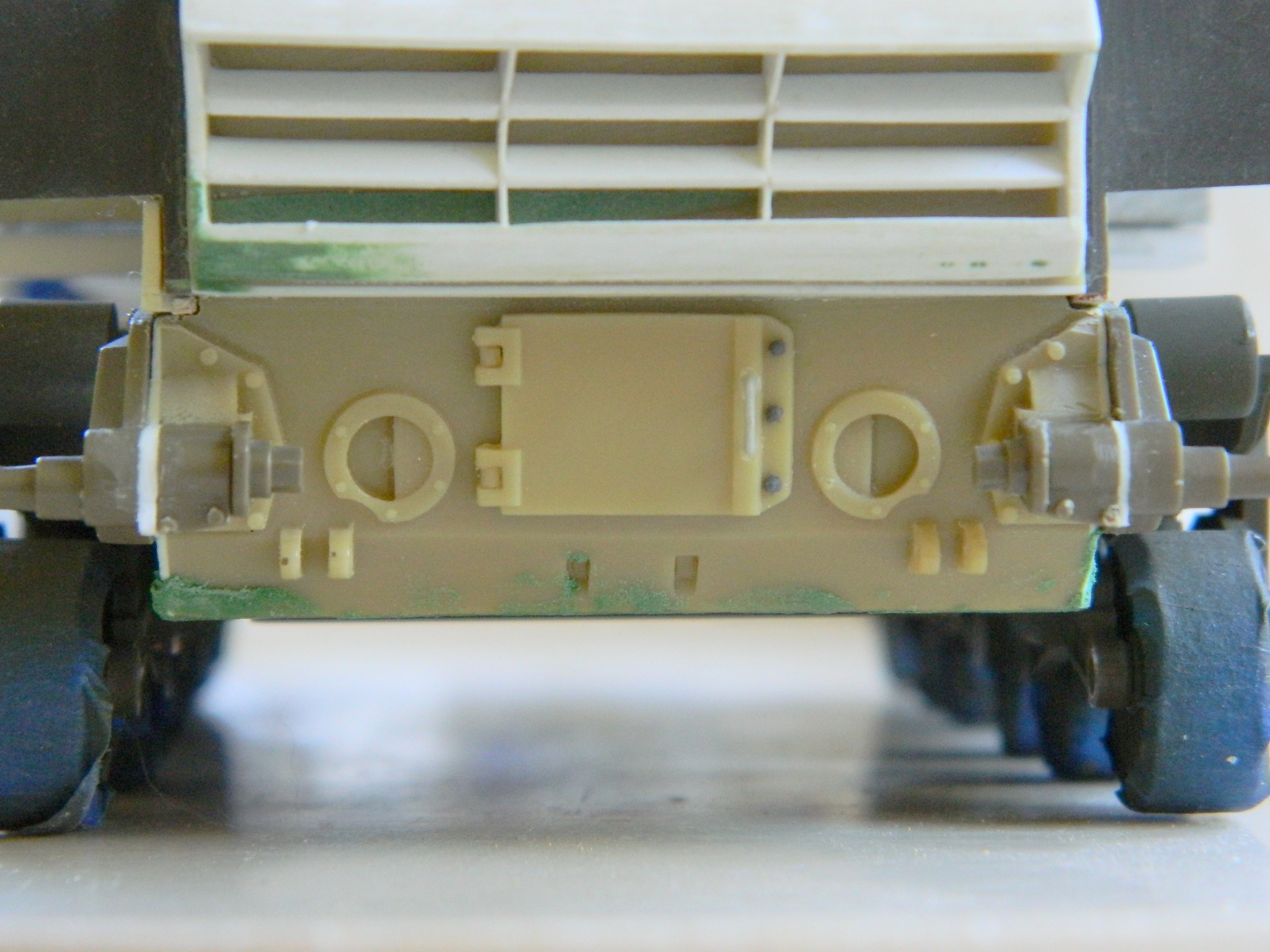
When I added the resin rear lower hull to the kit hull, it was too narrow. Unsurprisingly, the parts that attach to that too-narrow resin part turn out needing gaps filled, also:
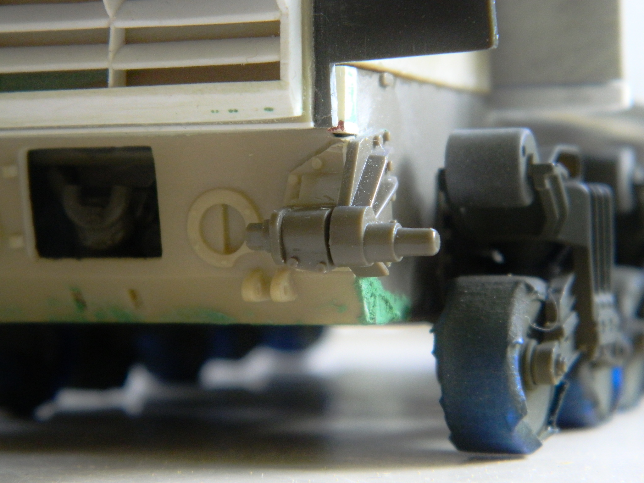
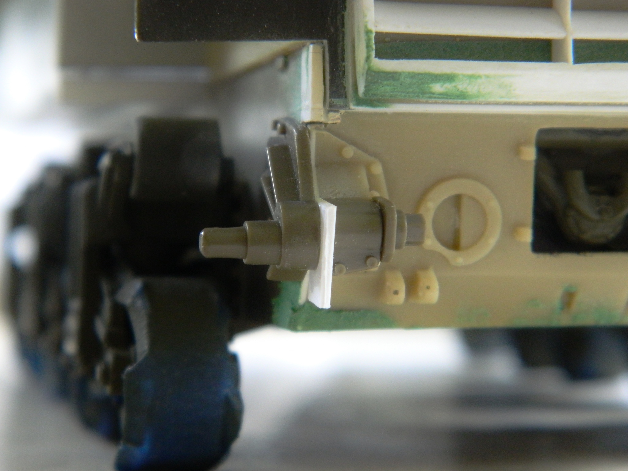
The lower rear inspection plate is bolted to the hull. The resin AM part was molded from the Tamiya part and, as Tamiya seems to do, the “bolts” were actually round. Grandt Line to the rescue: