Sometimes I repeat myself often a lot over and over… Here comes another (again some more). The smaller the details, the longer they take me to do. With the cockpits done, I turned my attention and effort back to the nose gear bay…which will be full of very small details.
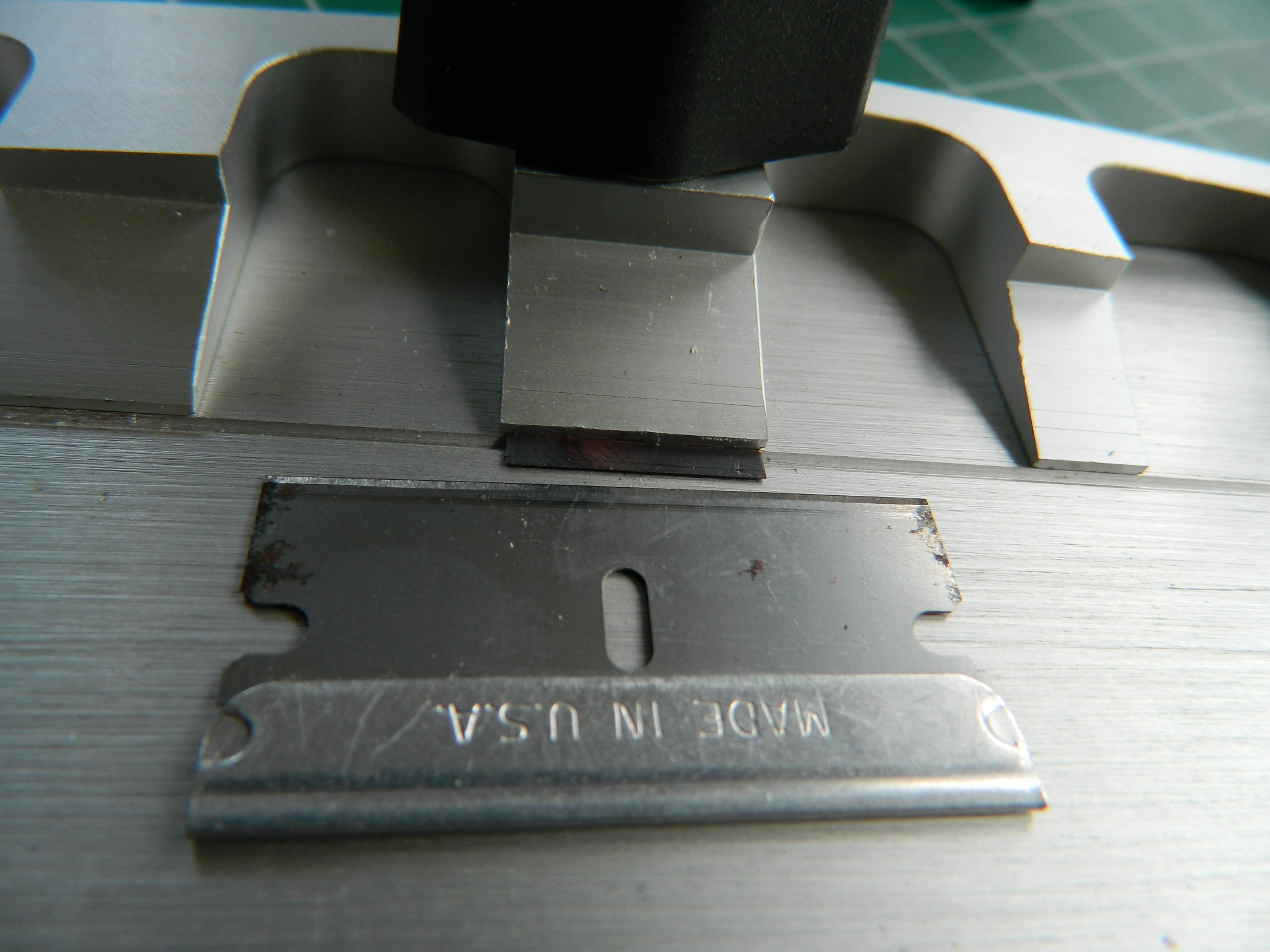
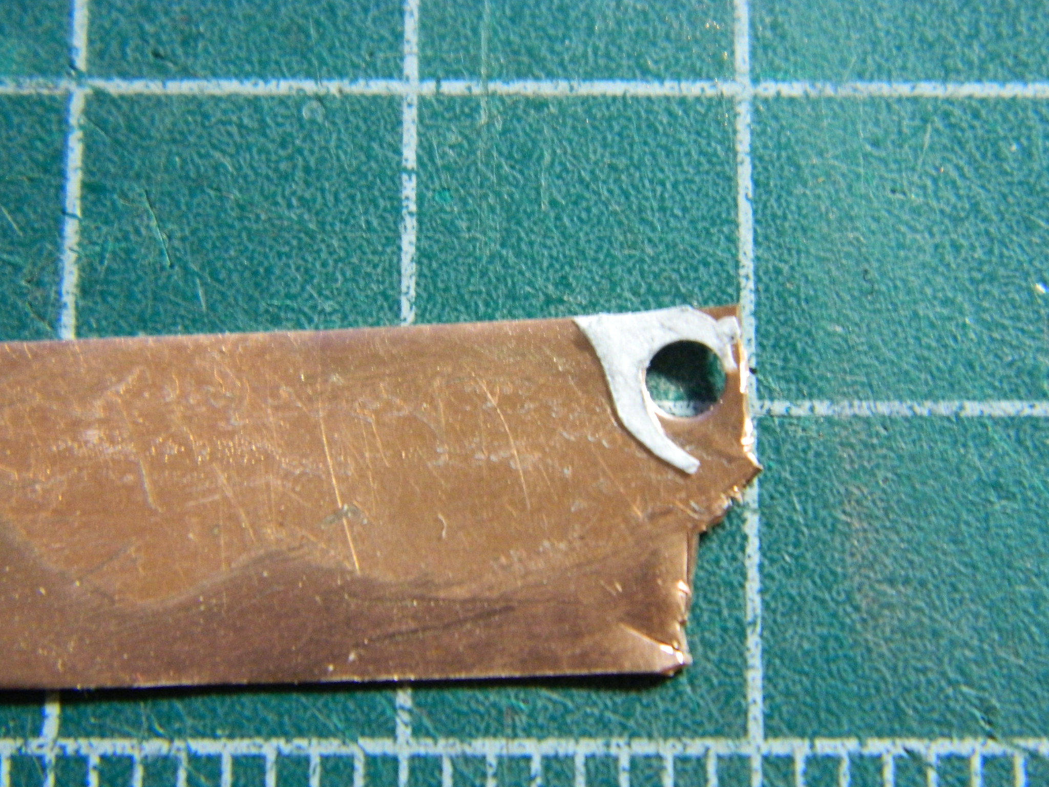
Sometimes instead of plastic sheet, I’ll make details from copper shim stock (.005″ (.127mm) and .010″ (.254mm) because that’s what I have on hand). There is a small “C” channel and rather than try styrene, I used .005 shim stock. To get tight bends, I’ve found that if I anneal the copper prior to bending, I can get much tighter and sharper bends. Once the copper cooled, I took out my PE bending brake. I used a needle to score my bend line (not because it actually scores it but because I need an alignment line to follow), fiddled with the copper until I had it correctly lined up, and then used the razor blade to make my ninety degree bend by slipping the edge of the blade under the copper that sticks out and lifting it up:

Worked well so I did it again and got this:

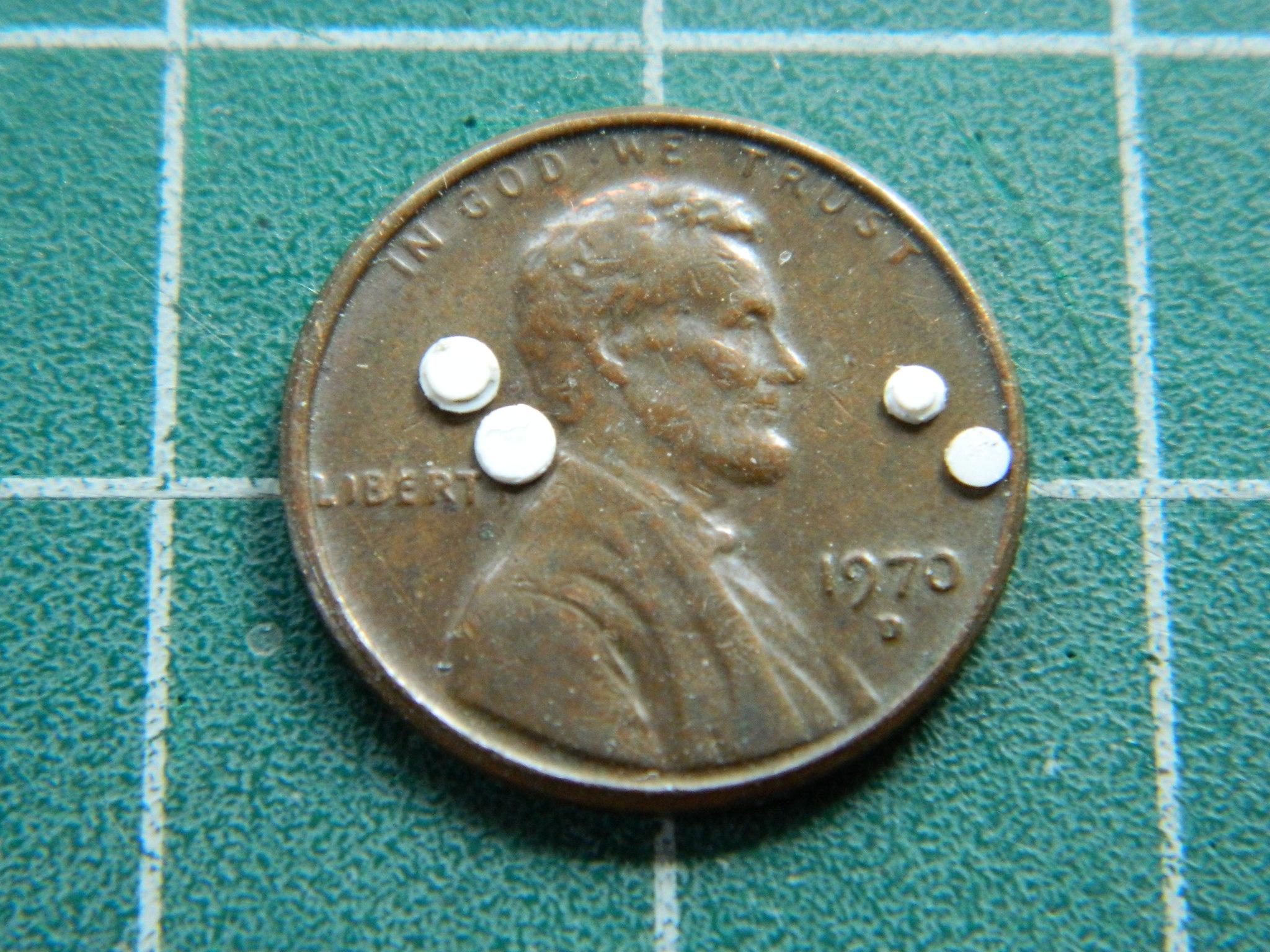
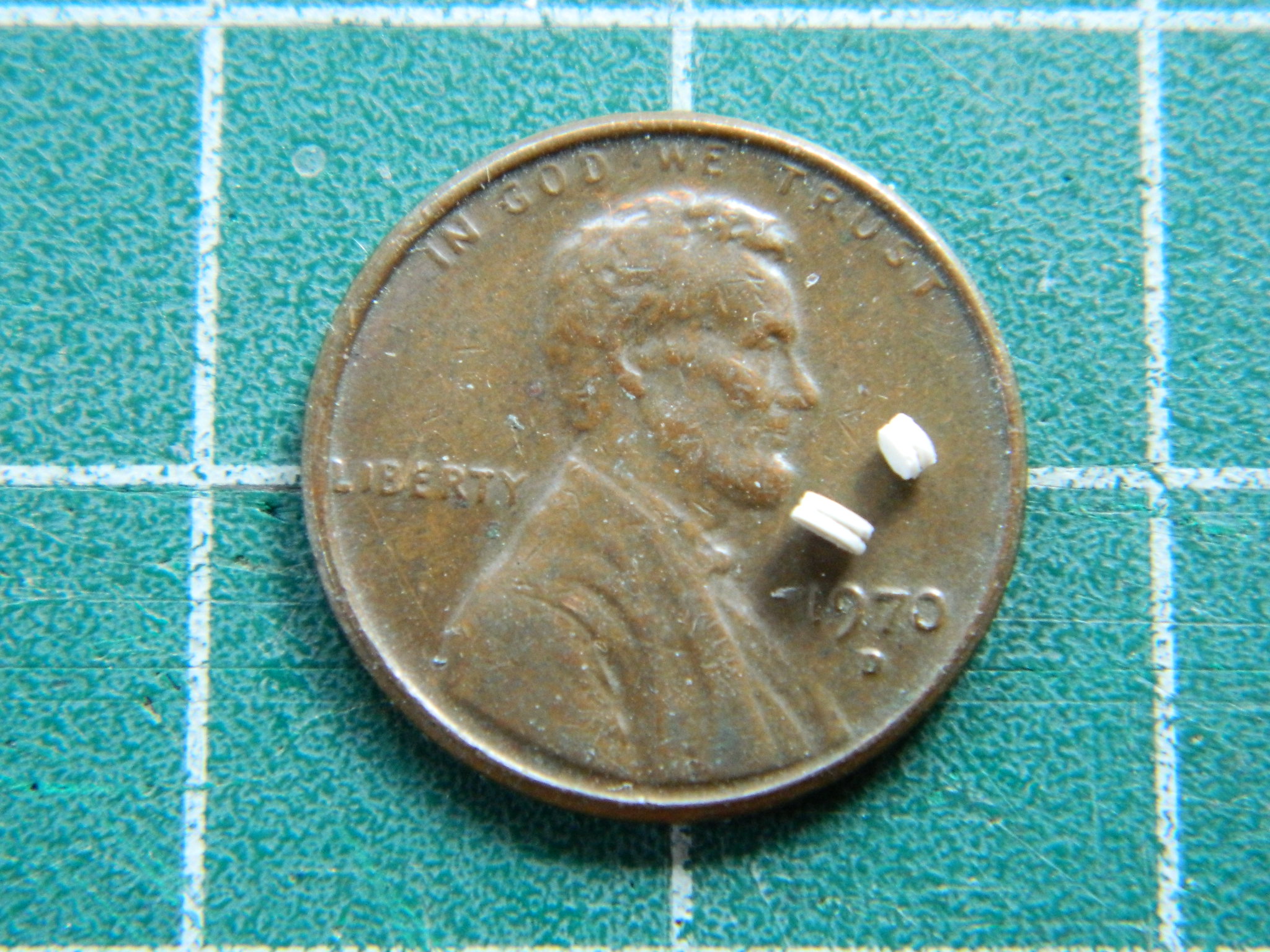
I had to make and add pulleys to one of the assemblies that populates the “C” channel. I used the punch and die set to knock out the inner part (.005″ (.127mm)), the outer parts (.010″ (.254mm)), and then assembled the pulleys and added them to the mount I made:
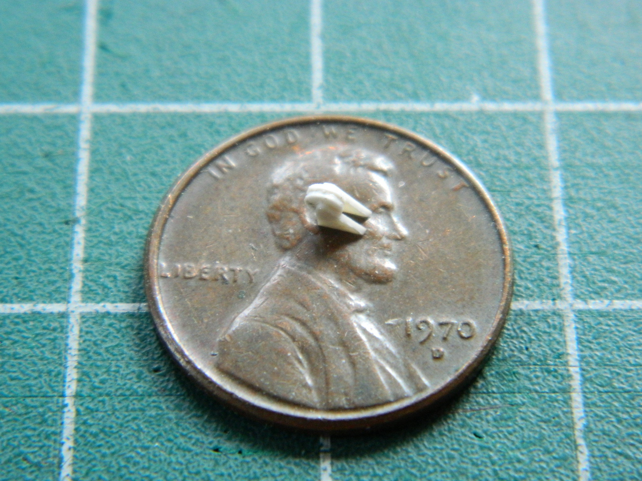
The “C” catch and its arms were also done with .005″ (.127mm) copper, its mounting done with little bits of scrap styrene, the pulley mount fleshed out, the connecting arm done with stretched sprue, the pulley added, and all of that added to the “C” channel:
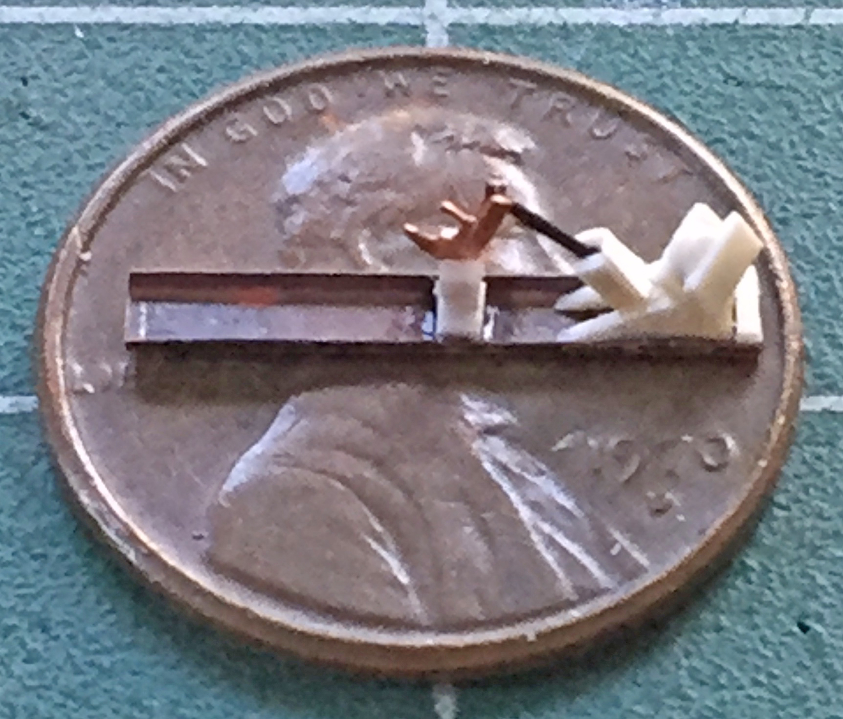
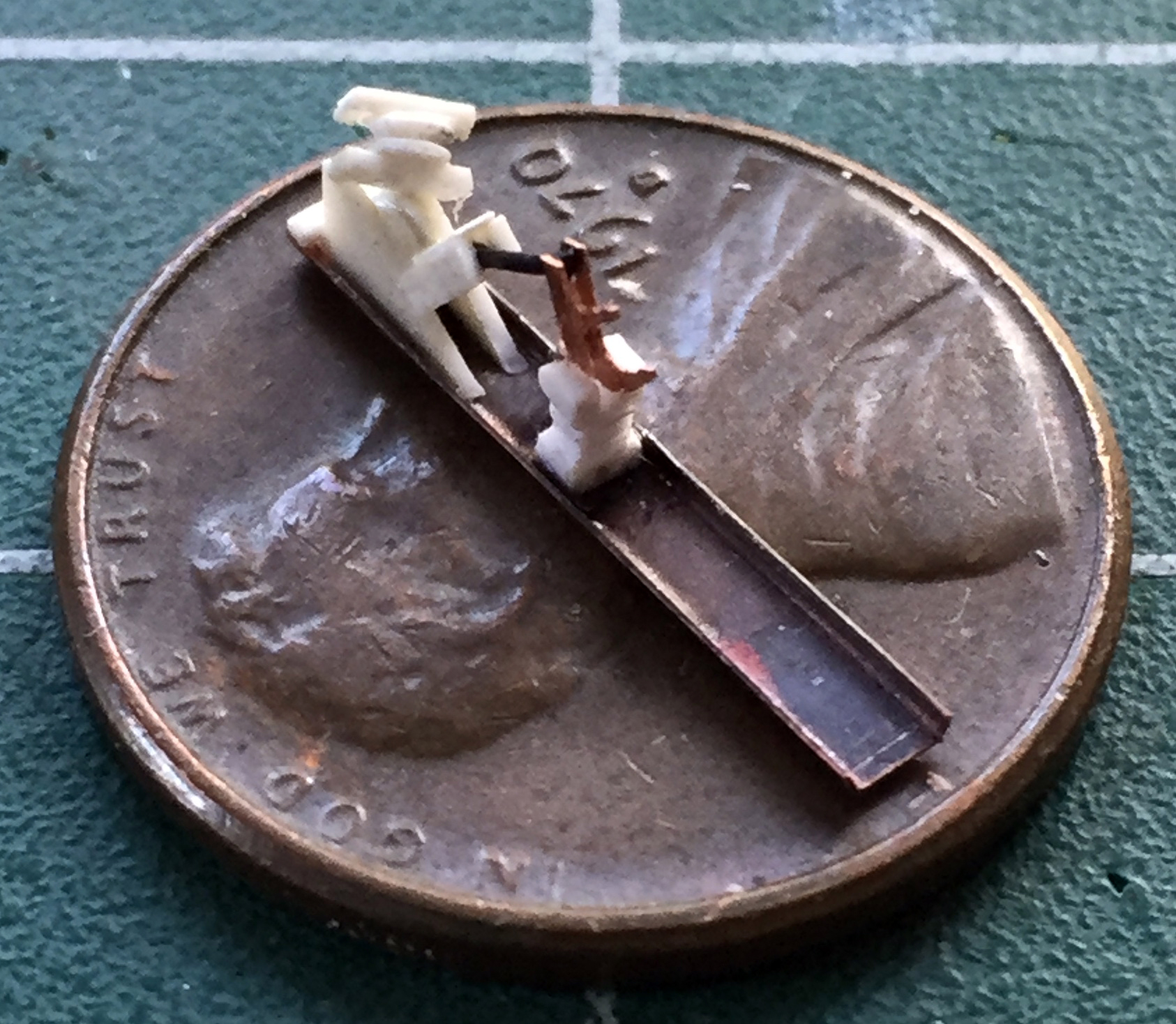
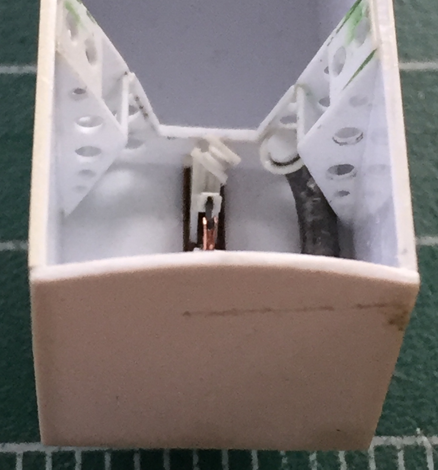
So before I either dropped it and broke it, or just broke it without the optional drop, I glued that assembly into the nose wheel box (the capped vent tube was .093″ solder [2.38mm] added earlier):

I had already built the liquid nitrogen tanks and was going to start adding lines to them. When I went to dry-fit them I realized that when I put them together, I didn’t have these sheets of insulation in place the way they are now:

Each sheet of insulation was made from .030″ (.762mm) styrene, which meant that the nitrogen tanks I built were .060″ (1.524mm) too wide, now. ::eye roll and forehead smack:: I had to saw them apart and put a thinner spacer between the ends. And just for the novelty of it, I checked reference photos. Some of the SR-71s have two oblong tanks, but the main references I’m using show only one tank being oblong; the other is round. Since I’m going to have to disassemble ’em anyway, I decided to do one oblong and one round just for the eye-candy aspect of it. I would rather do what tail number 972 has but I couldn’t get under the kite to see what’s in there so I decided to go with one round tank:
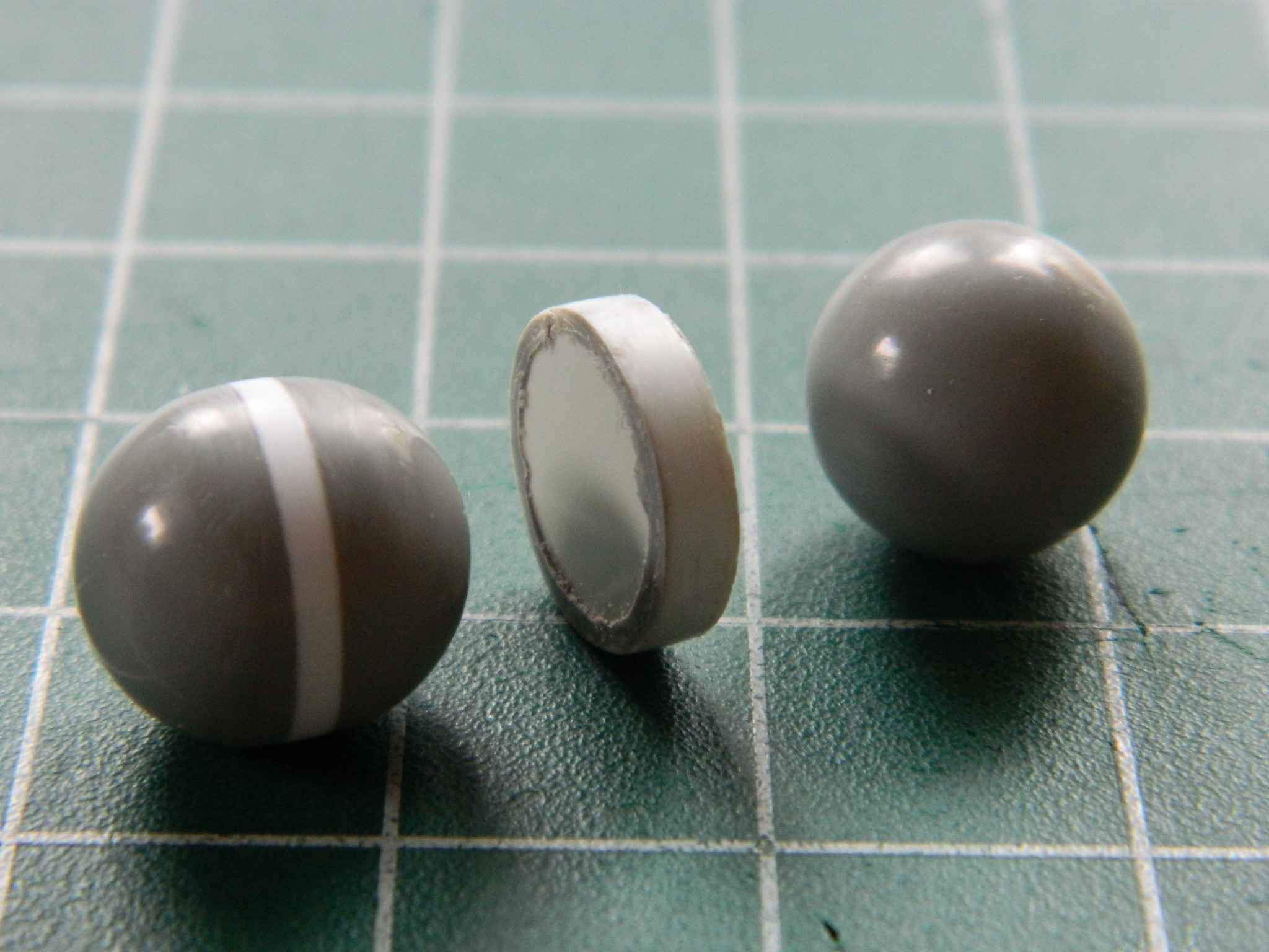
I added the various lines to the oblong tank using solder, copper wire, and stretched sprue. The discs were punched out with the punch and die set:

TOTALLY out of sequence (mine, of course), I decided to try an idea that had been rattling around under my (profoundly sparse) wig for a while…
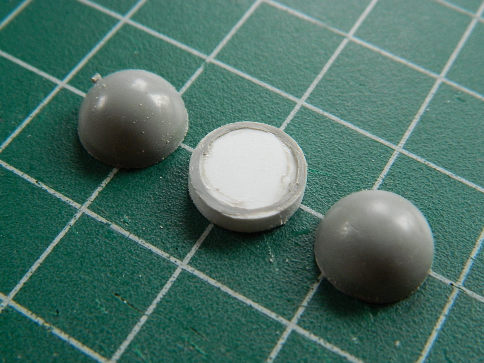
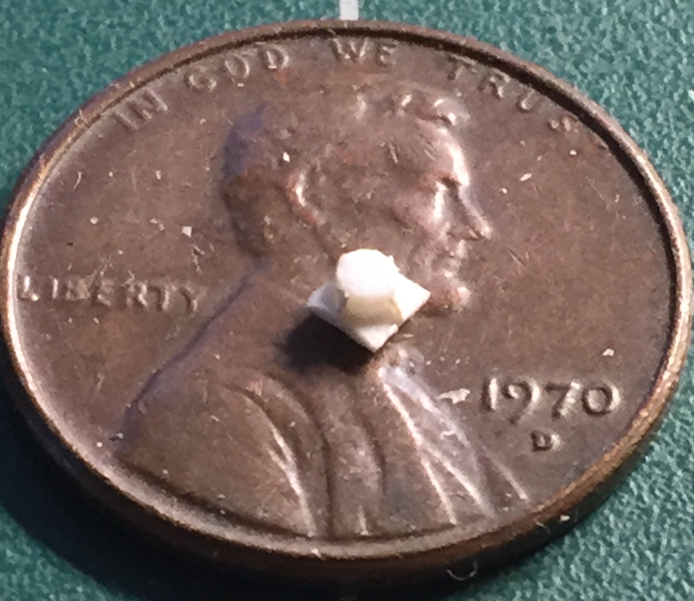
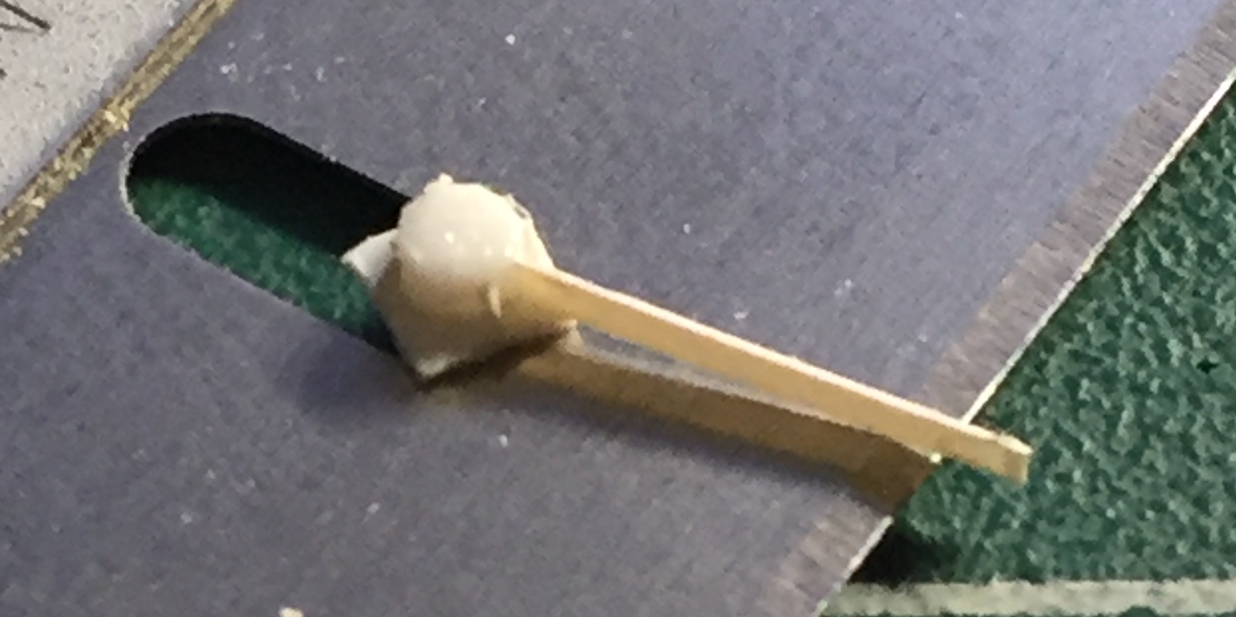
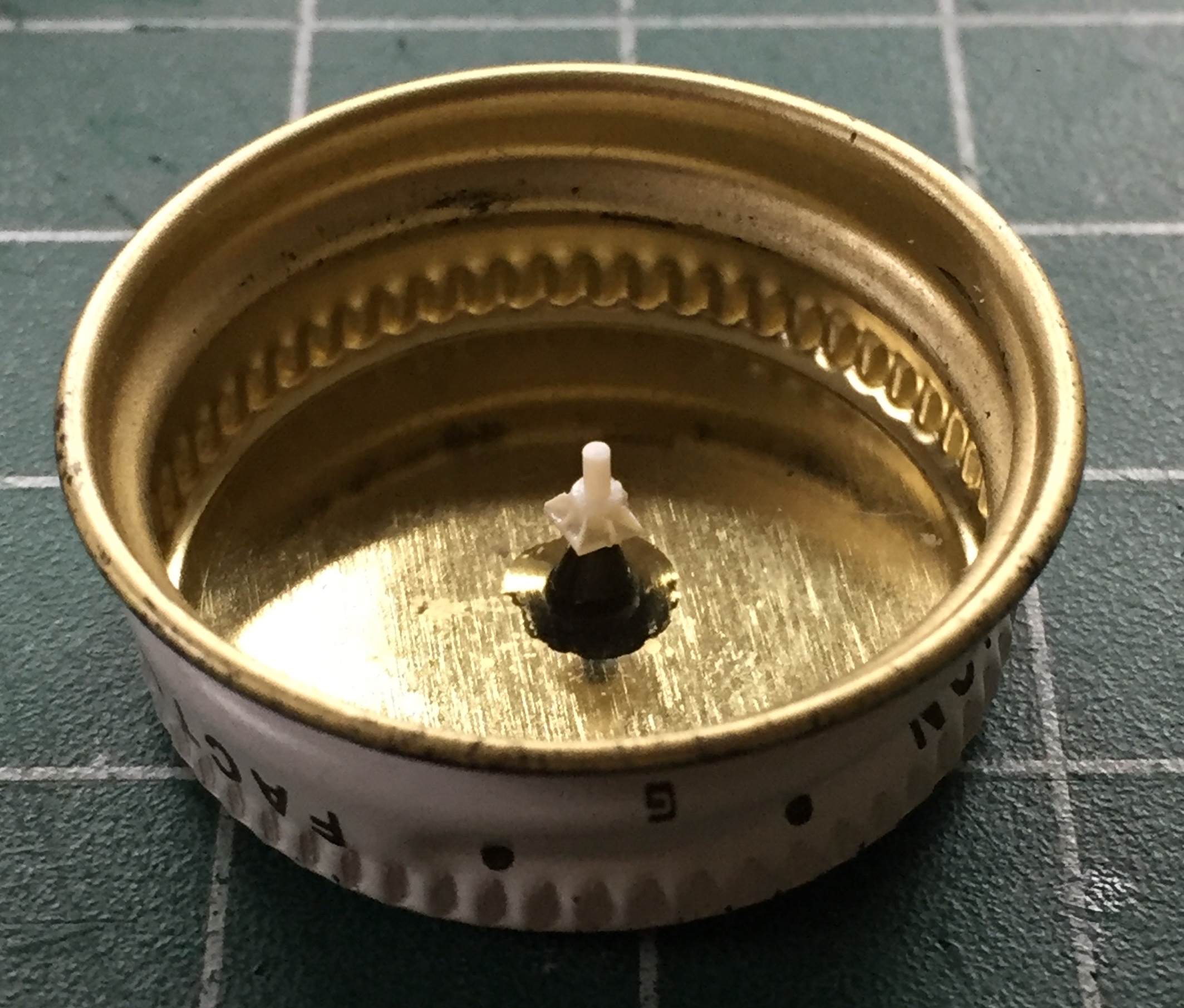
I do NOT like trying to replicate a clear item with opaque paints. (That’s sort of like getting drunk every night to promote sobriety.) There are two very prominent landing lights attached to the strut of the nose gear and the only parts on hand are opaque. Gah. I chucked a piece of clear acrylic rod into my lathe and turned a section down to the diameter and shape I wanted. Then I used progressively finer grit sandpaper to remove the steps left by the cutter and then polished out all the marks left by sanding paper. Once satisfied, I cut the work from the acrylic rod, which left a small stub on the end. Instead of cutting that off, I decided to use that to drill a SMALL hole (.0135″ [.343mm]) to replicate the bulb. I dipped the tip of a needle into black paint and stuck it in there, then used Molotow’s “Chrome” pen to create the reflector. So far I’m very pleased with the results (only time will show me how the “Chrome” accepts the black paint it has to have on the exterior):

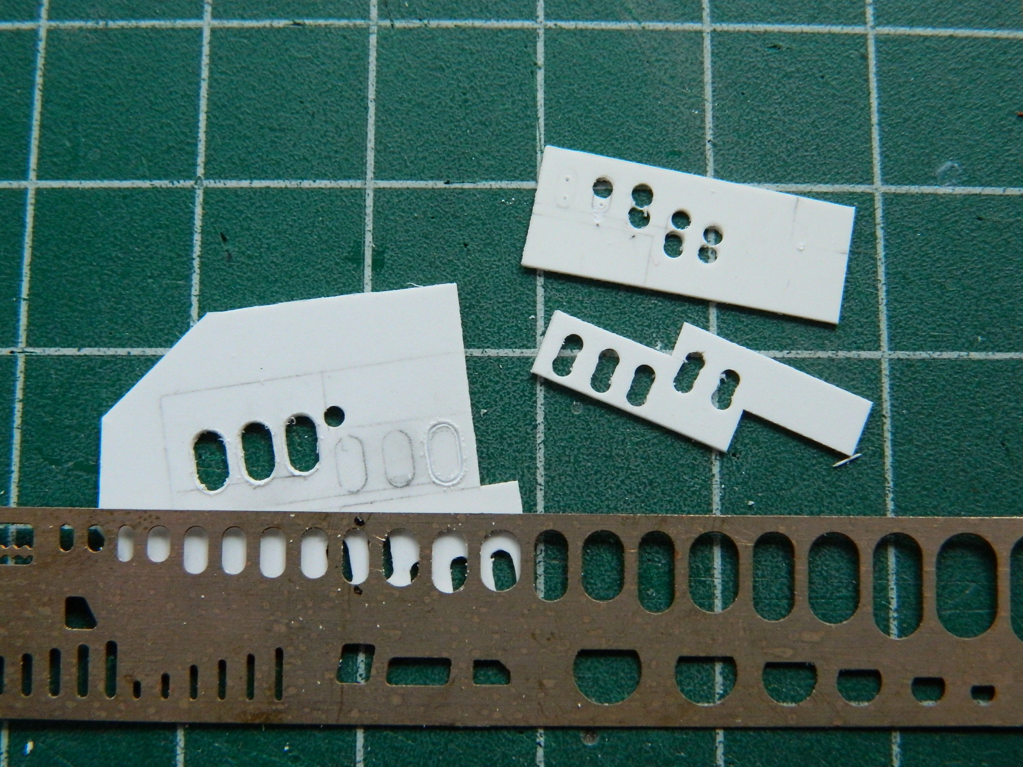
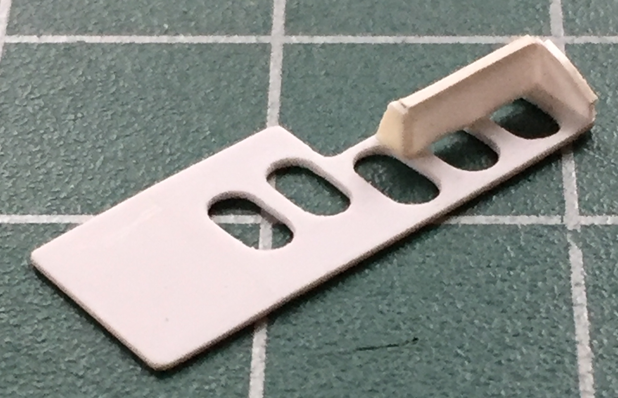
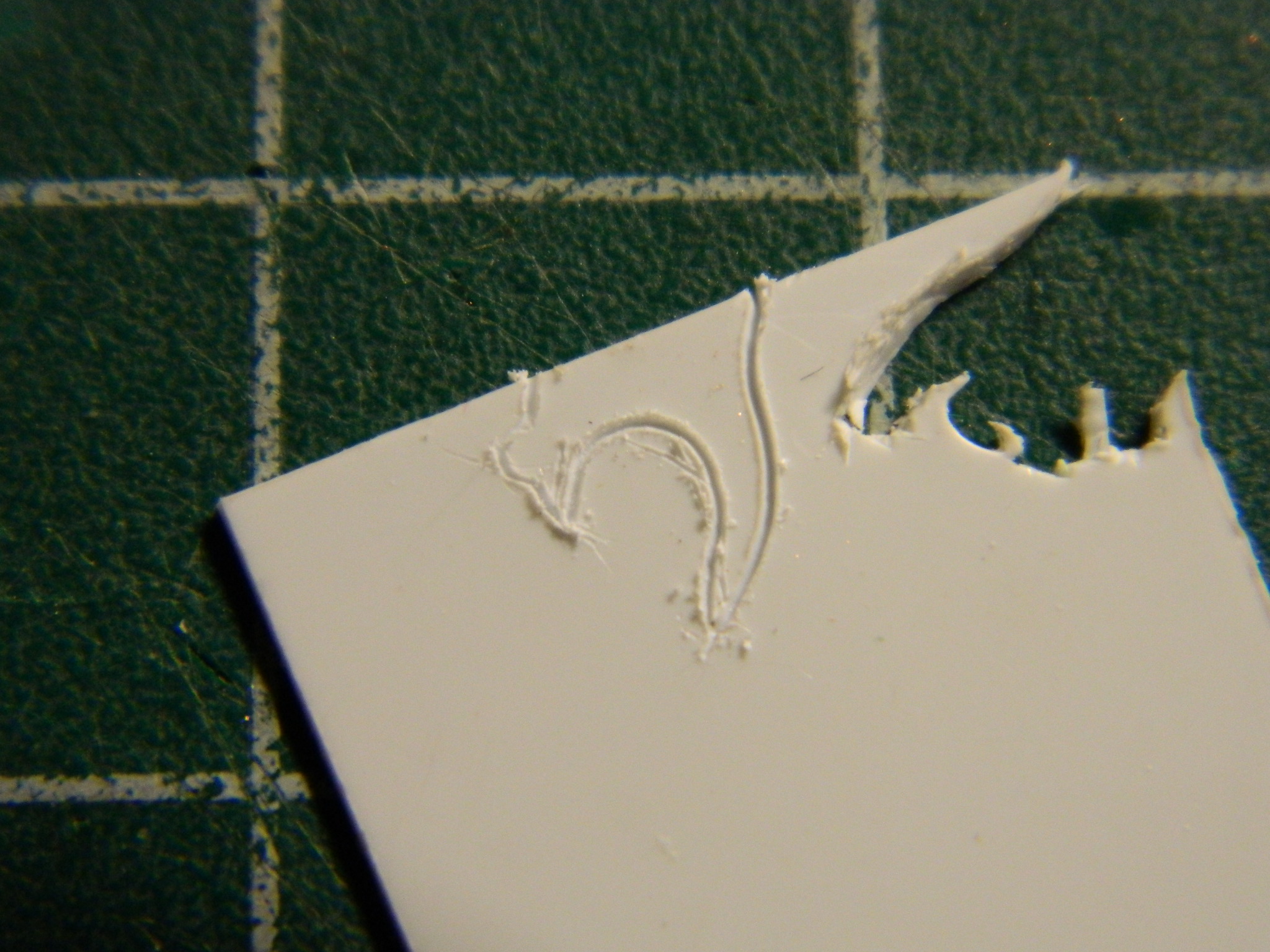
A very prominent feature on the starboard wall of the nose gear bay (that’s the right side, if I’m not trying to impress) is a panel full of plumbing, pressure regulators, and other varied Mysterious Bits and wiring. NObody makes this part, either*, so, I started by making the panel. I used a scribing template to be able to make consistent size/shape cuts. Well, not “cuts,” exactly…I used a needle to make repeated passes until I was able to cut through (as you can see below, I tried a couple of different techniques, starting with “outline, drill, connect the holes, pout, discard, try something else”):
The scribing-through worked the best:
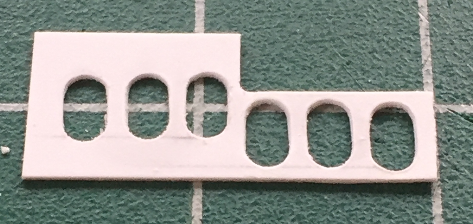
And…as that turned out I was a bit incorrect. There’s only two of the upper ovals, so I cut the offending hole off:
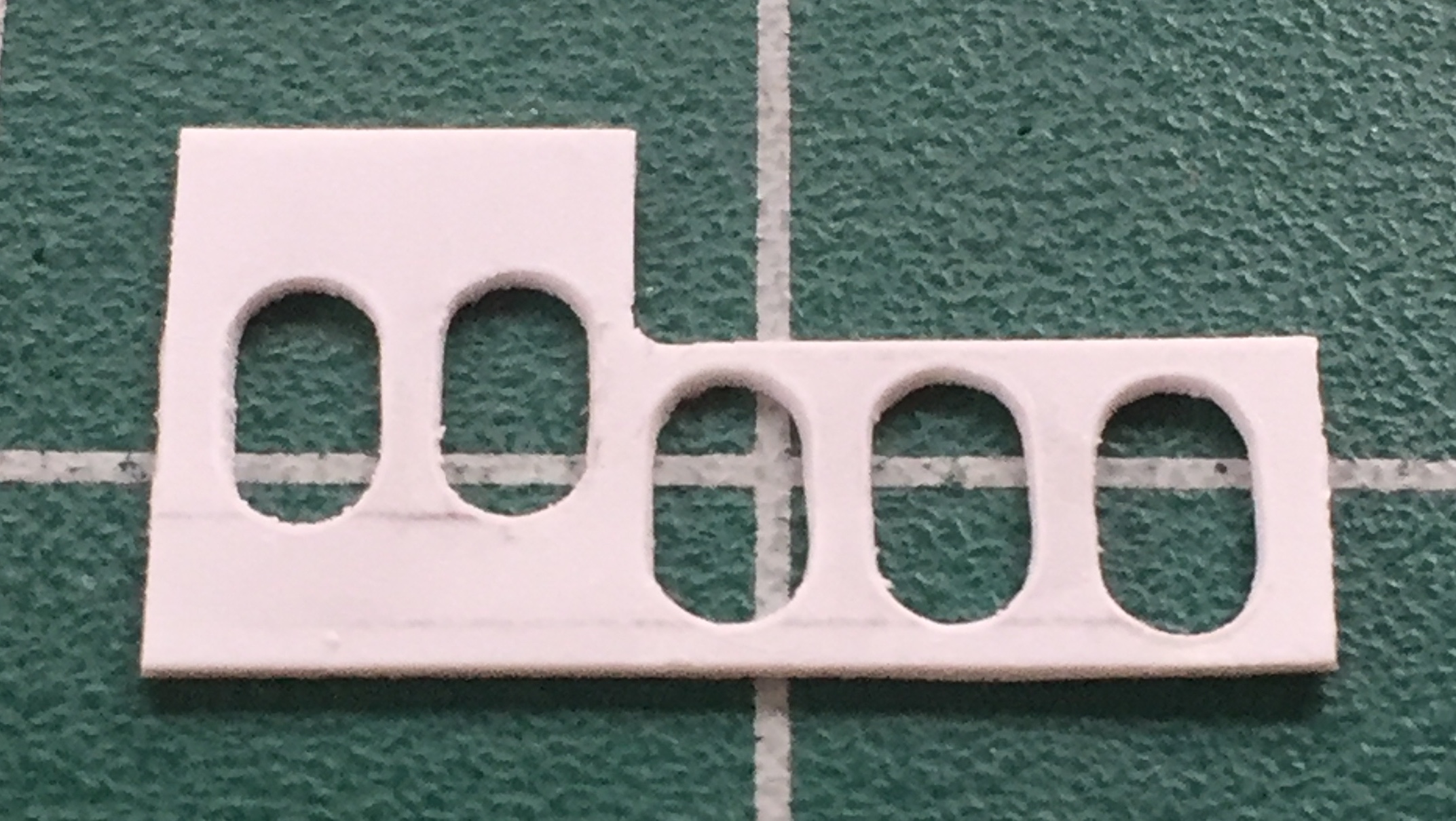
And now that this panel isn’t long enough, I added back what I had to remove:

Next was to start making the various parts that live on that panel. I started with a mounting bracket for what appear to be pressure regulators. I used .015″ (.381mm) styrene for the mounting bracket and .005″ (.127mm) styrene for the pronounced lip:

With it done, the bracket was glued to the plate:
Due to their shape and small size, rather than use styrene to make these mounts, I went with .005″ (.127mm) shim stock, annealed and bent as earlier, with holes punched out:
Now I need to populate the brackets. I started with (what I assume to be) the pressure regulators:

Since adding those fins to such a small piece was such a joy, I figured I’d use the thermo-mold compound to make molds and cast resin parts:
Yeah, well, no. I was reminded that the thermo-mold compound gets HOT. And styrene melts when things get HOT. Which is just what happened. Okay, so, I’m not going to be able to mold the entire part. But I can mold the hardest area to make which is the finned base, and that’s what I did. You’ll see below that one part is resin (the darker of the two), the other part the master that had the small details melted off and was fixed. You’ll also see where I added other Mystery Bits and had to add to the plate AND fill in most of the two oval cutouts in that addition:

I added the copper colored box on the upper left of the plate (body is .005″ [.127mm] copper and the face with the oval cutout is .010″ [.254mm]), added wiring (eight strands of 48awg copper wire), wiring connector, and plumbing connections:
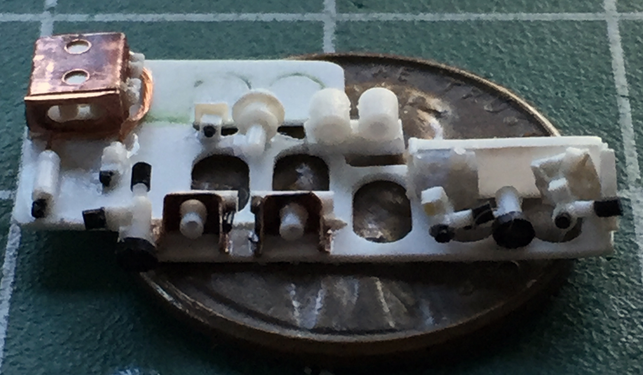
As I’m merrily (medications help) adding various lines, it occurred to me that maybe I should dry-fit this to see if it fits before I get carried away (further) with it…and yeah…it fits:


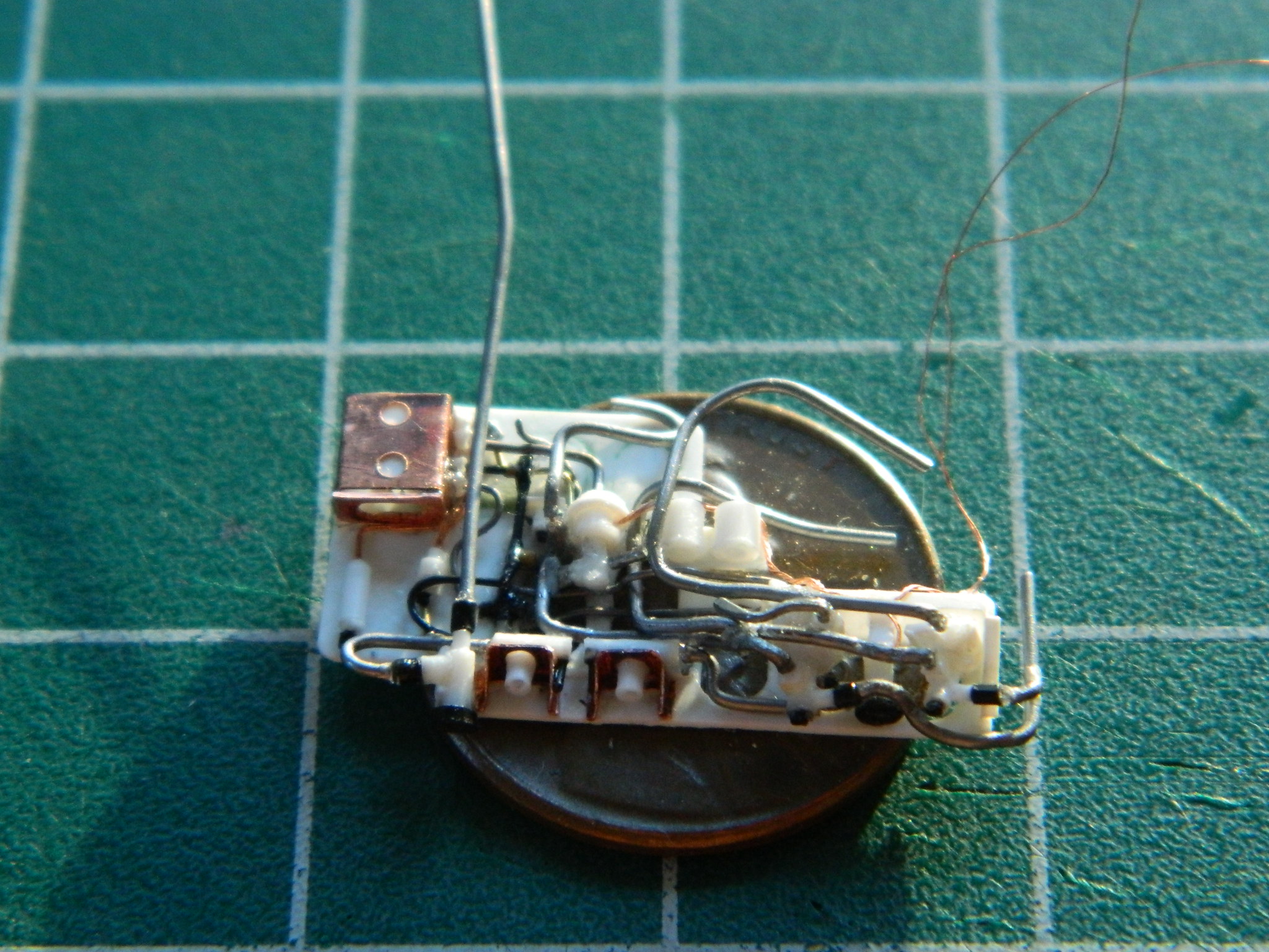
I kept at it, adding solder (.010″ [.254mm], .015″ [.381mm]), wire (26awg, 24awg, as well as more 48awg), and sprue (Eyecrometer-approved diameters), and figured that this will do (the lines that aren’t connected to anything will get connected to the nitrogen tanks):
And THAT all took some of October and all of November!
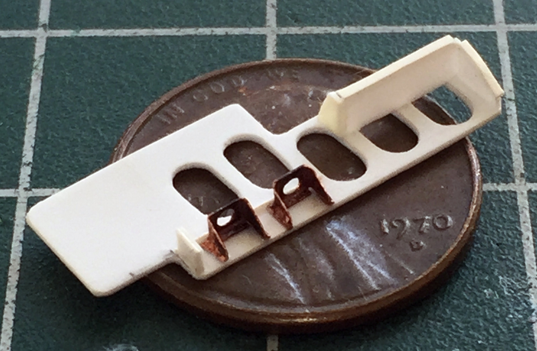
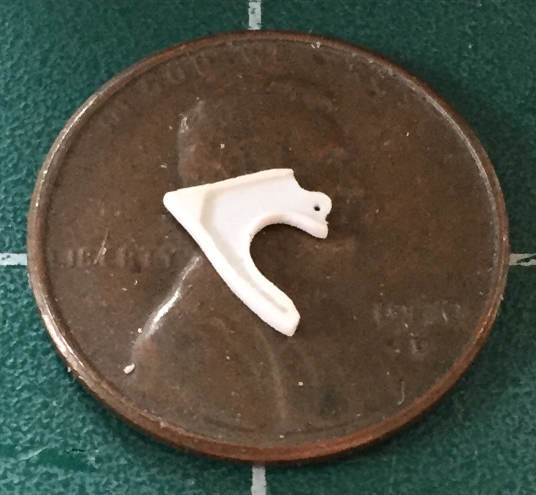
Inside the front landing gear bay are two large latches/supports that grab/support (which is what “supports” do, one supposes) the main strut of the nose gear. I copied the shape (and hopefully the size) to the adhesive strip of a Post-It pad. Doing it this way means I can trace around the template without the frustration of trying to hold something SO small and, well, paper thin, in place (a lot). Tracing onto the adhesive strip allows it to stick. I used a piece of .005″ (.127mm) copper as my working template (the hole was punched out):
Having the shape in copper made it easier to file the shape to its final dimensions:

Right after the above photo was taken, I picked the copper template up with my tweezers and PING…it vanished, never to be found again (of course, my cat will find it, eat it, and maybe I’ll see it again after the vet digs it out of whatever part of her alimentary canal it decides to puncture). So I made another one. Again, I traced around it with a needle until I worked through the .015″ (.381mm) styrene:

The original part on the aircraft is cast (probably titanium, but I’m not sure) and has an evident lip (sorta like I do) that goes around the periphery. I added that using a strip of scrap .015″ (.381mm) styrene:


I sanded the exterior lip and filed the interior lip to get the thickness I wanted. On parts this small, where things need to be filled, I don’t use putty (there really isn’t enough of it to hold to itself or the plastic). I add small scraps of styrene and cut, file, sand, them to shape once the glue completely cures:
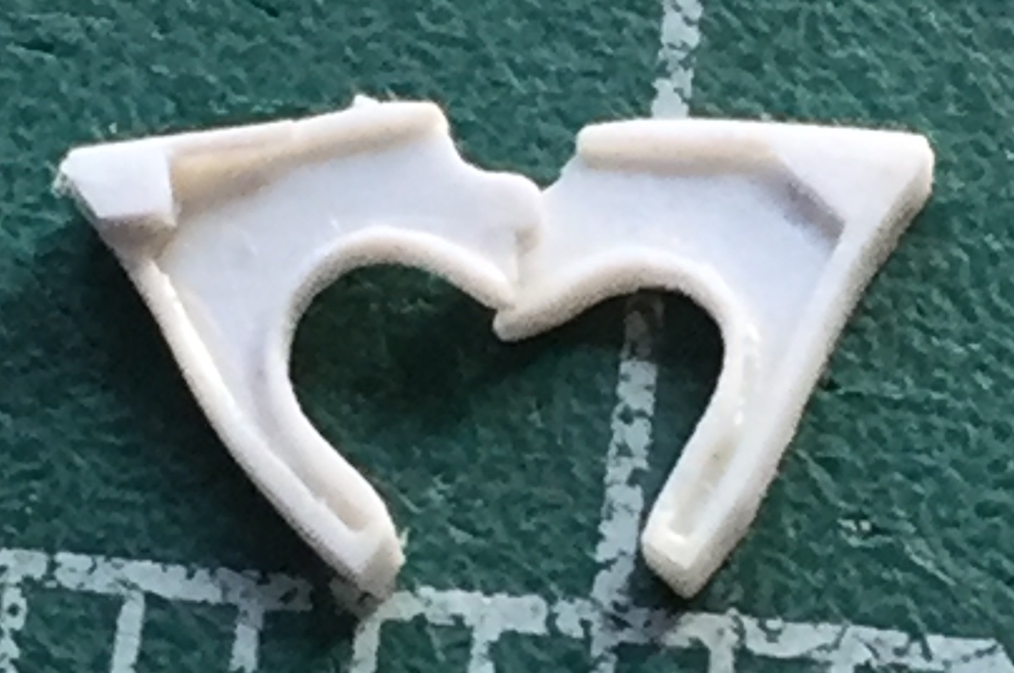
Right after the above photo was taken, I realized I put the lip around the round inner section of the right clamp/support on the wrong side of it. Yeahwellfine. I cut it off and redid it on the proper side…then I went and had more coffee. Once the coffee had calmed me down and made my approaching-ancient hands so much more steady, I took 28awg copper wire and wrapped it around a needle to make the springs that these latches will get:

I am SO looking forward to making the shock absorbers to fit inside those springs… (Remind me again why I don’t work in 1/72 scale?)
*Well, nobody made the parts when I started this build. Of course, once I had this section of the nosewheel bay built and installed, I discovered that Metallic Details (if memory serves) (yeah…like THAT ever happens) does make most of what I scratch-built in resin, now… ::eyeroll:: (Then again, I think what I made looks better.)

just an astonishing OMG – yet again…(speaking of repeating oneself 🙂 and the kitty better not find the itsy-bitsy part!! Hope you enjoy December – will that finish is up??
>
LikeLike
At the (rare) risk of repeating myself, thanks! “Enjoy” ANY winter month?! BWA hah hah hah… And no, IF this is finished by December, it will be *next* December. There is a metric butt-load of work yet to do.
I’m still working on one (out of three) landing gear bays. Then the landing gear has to be scratch-built (at least two out of the three, perhaps all three). The engine nacelles will get a lot of attention (which equates to time), there are details that have to be made for the fuselage (body of the aircraft), including fixing the large gaps in fuselage parts EVERYwhere, and on and on and ON. Hell…if I’m done by December 2018 I will be *most* impressed by myself!
(And, naturally, now that I no longer need that itsy-bitsy part, of course I found it…and not in the cat OR catbox.)
LikeLike
Awesome, Wayne. Simply awesome. Your dedication to detail is inspiring.
LikeLike
Thanks, Al…you’re right. I *am* crazy.
LikeLike
I’ve known about your capacity for attention to detail for a long time, but I’m still amazed by the tiny scale of these details!
I’d love to see a shot of a final assembly next to a reference photo to see how close you get. You may not think it’s good enough to show that, but I’m sure all of us will be amazed!
LikeLike