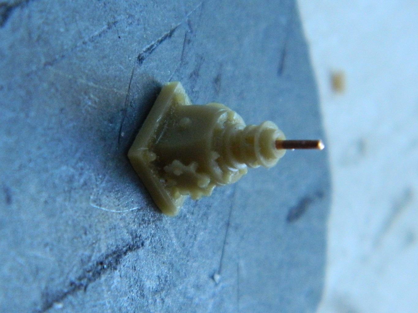
And now the driver’s controls are all trimmed and glued. I added copper wire to run from the floor to the linkages (on the actual Sherman, the rods near the floor attached to the steering levers):
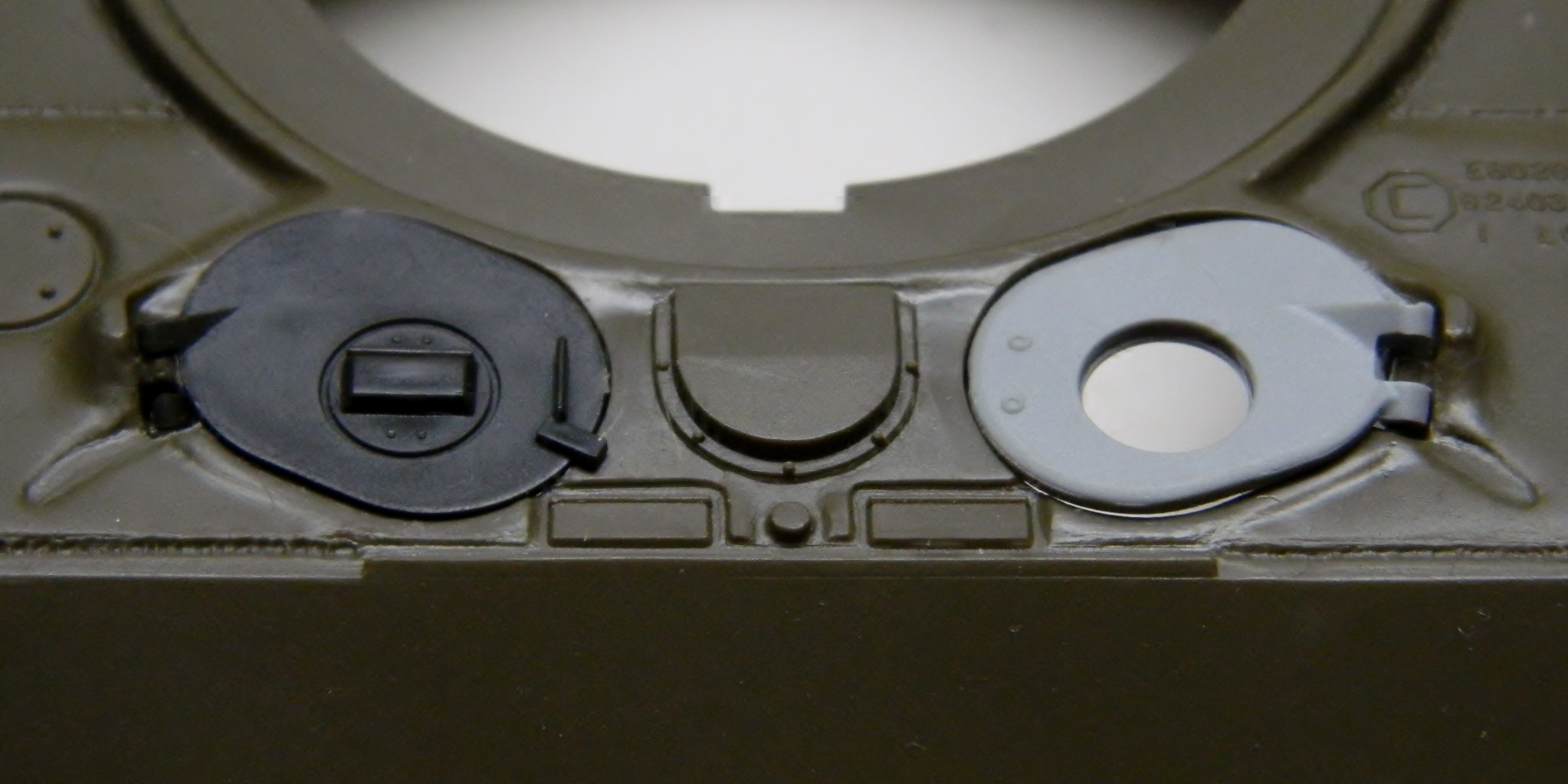
In the photo below, the kit hatch is on the left and fits, the one on the right is from a different kit. So of course I’m going to be using the hatch that doesn’t fit because it offers better details:
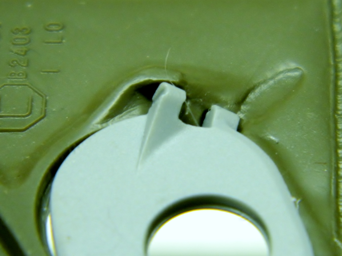
To make these hatches fit required reworking the hinges on the hull top, as you can see if you compare the hinge at left, using the kit hatch, with the hinge at right:
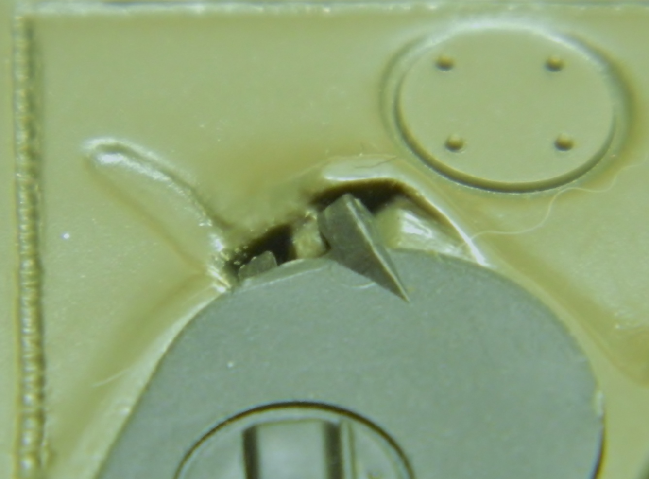
That starts by cutting away the kit’s hinges, adding styrene bits, and my structural putty:

The one on the right is done, now to finish the left:

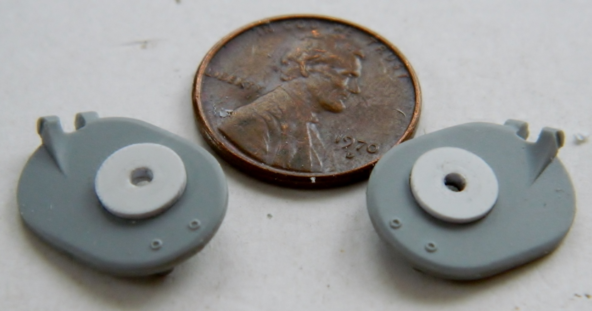
The round holes in the hatches are where the periscopes’ mounts rotate, so I have to make those mounts. A piece of styrene chucked into my drill, turned to the proper diameter, and then filed/sanded to the correct thickness:


Feedback from Sherman crews in the field showed that the hatches for the driver and co-driver were too small and made un-assing the tank difficult if it got hit and/or started burning. When the hatches were redesigned to be larger, a couple of other design changes had to be made to accommodate the new hatches. One was changing the front glacis plate from a 60° angle to a 47° angle. The new glacis plate offered better protection (even though it was more vertical to incoming fire) because its design eliminated the protrusions of the hatch boxes (which had vertical faces) and was one piece, its face unbroken except for the bow machine gun. The new plate as also easier to produce because there was substantially less welding required to it.
The other change necessitated by the new hatches was to the bustle (the rear extension) of the turret. The larger hatches were hinged so that they opened forward and the bustle needed to be higher for clearance to allow the hatches to open.
The low bustle on the left, and high bustle on the right. Note the angle of the top of the bustle:
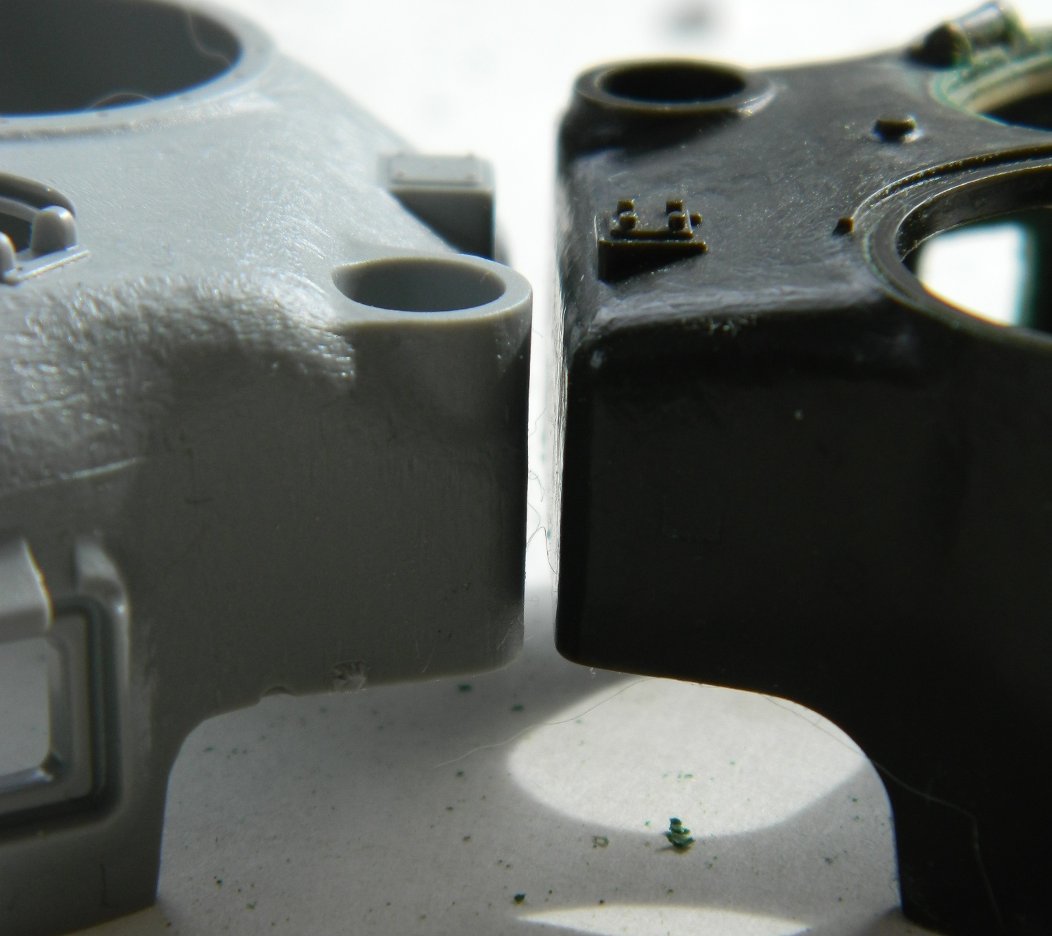
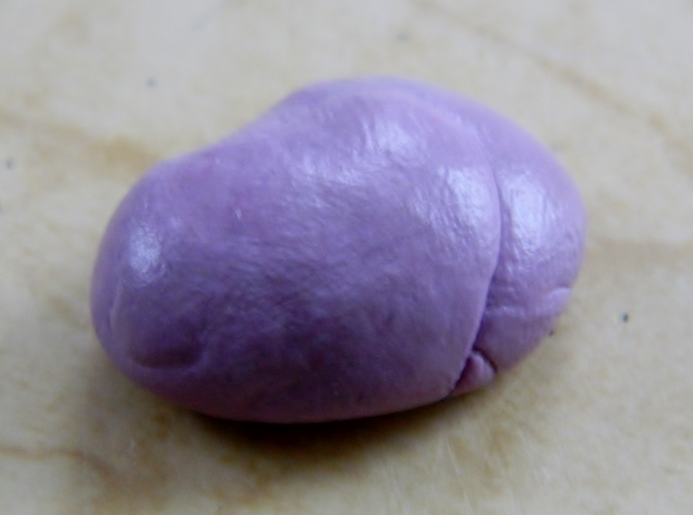
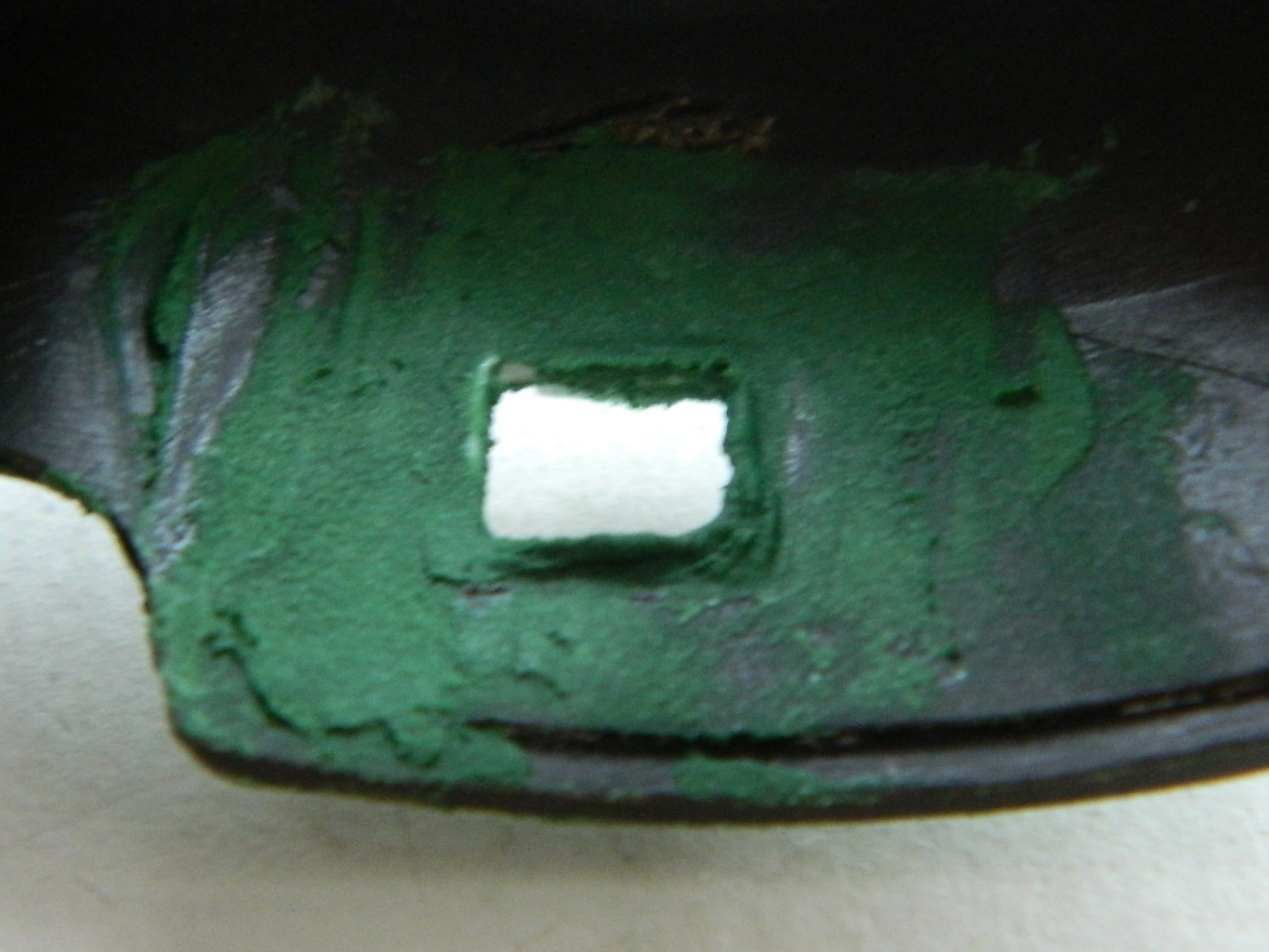
The square opening on the left side of the turret is the “pistol” port (and I have no idea why they were called that because that wasn’t the function of the port – its purpose was for the loader to toss empty brass from the 75mm out). Tamiya had no intention of this port being open and I do. If the turret on the left had been a high bustle turret I would have used that instead. So I decided to use the port. I briefly considered cutting the ports out and grafting the open port (and its detail) to the high bustle turret, but that would sacrifice a part I may want to use later on. Instead, I decided to take a mold of it and cast a copy:


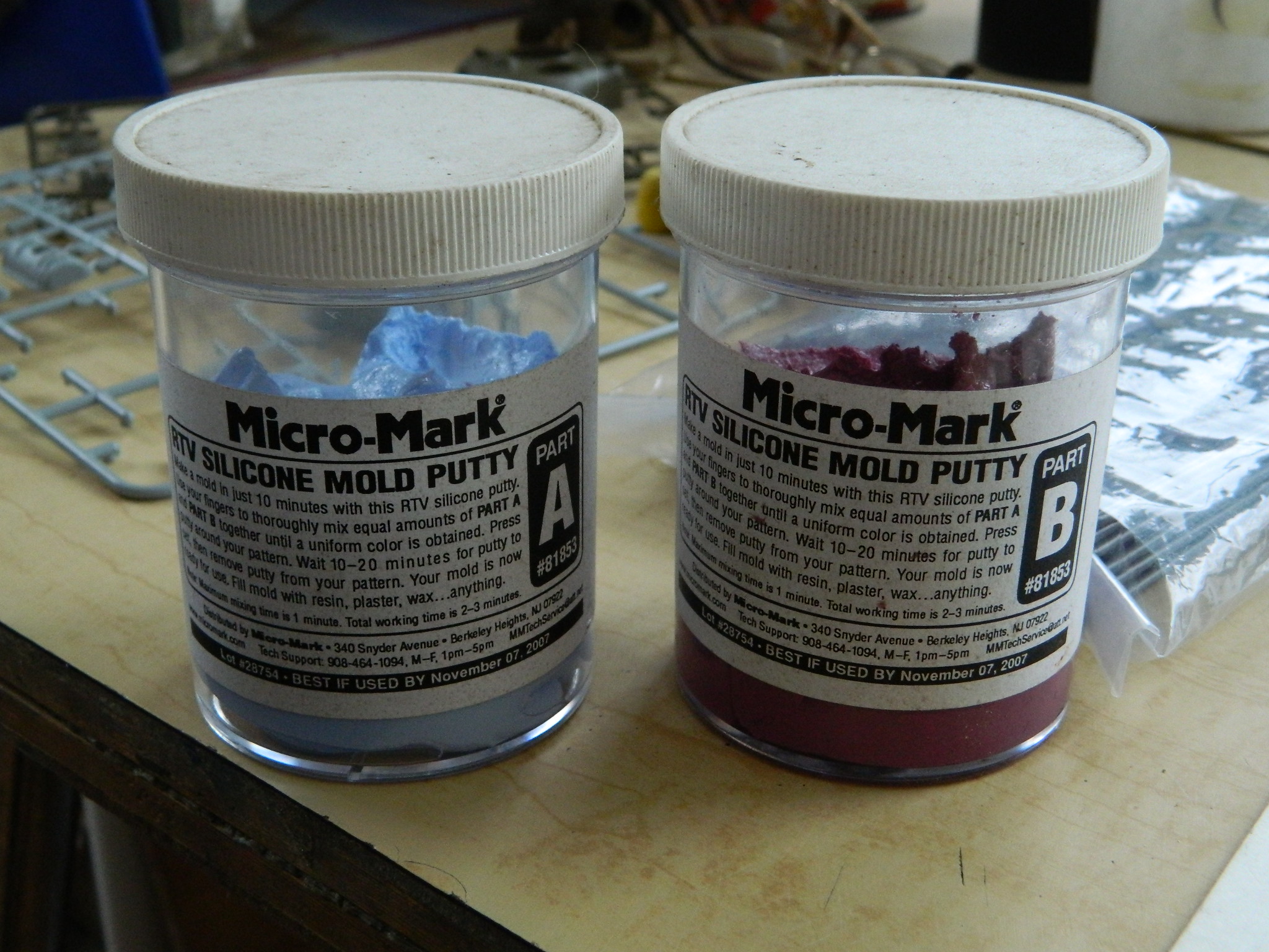
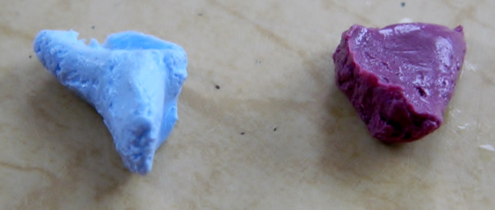
I used mold-making putty I have, combined the two parts, and took a mold of the gray turret’s port:
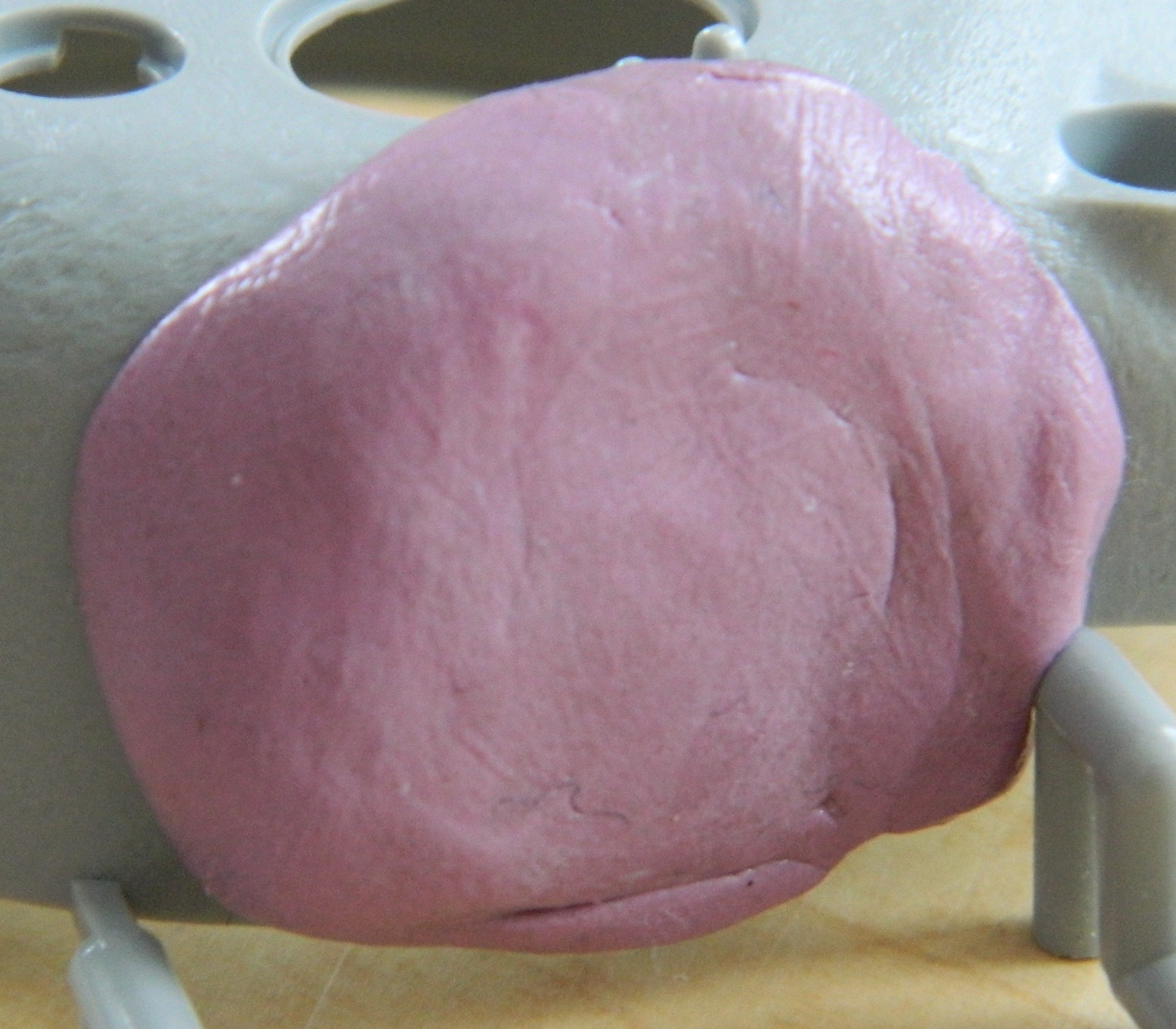
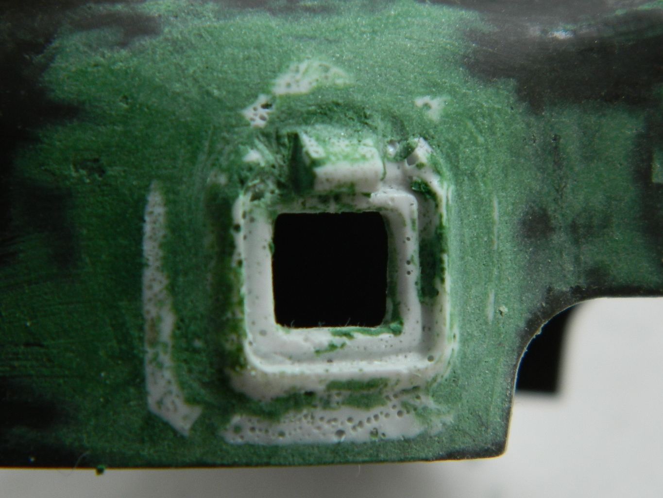
The next day after the molding putty cured, this is what I got which I then filled with my structural putty:
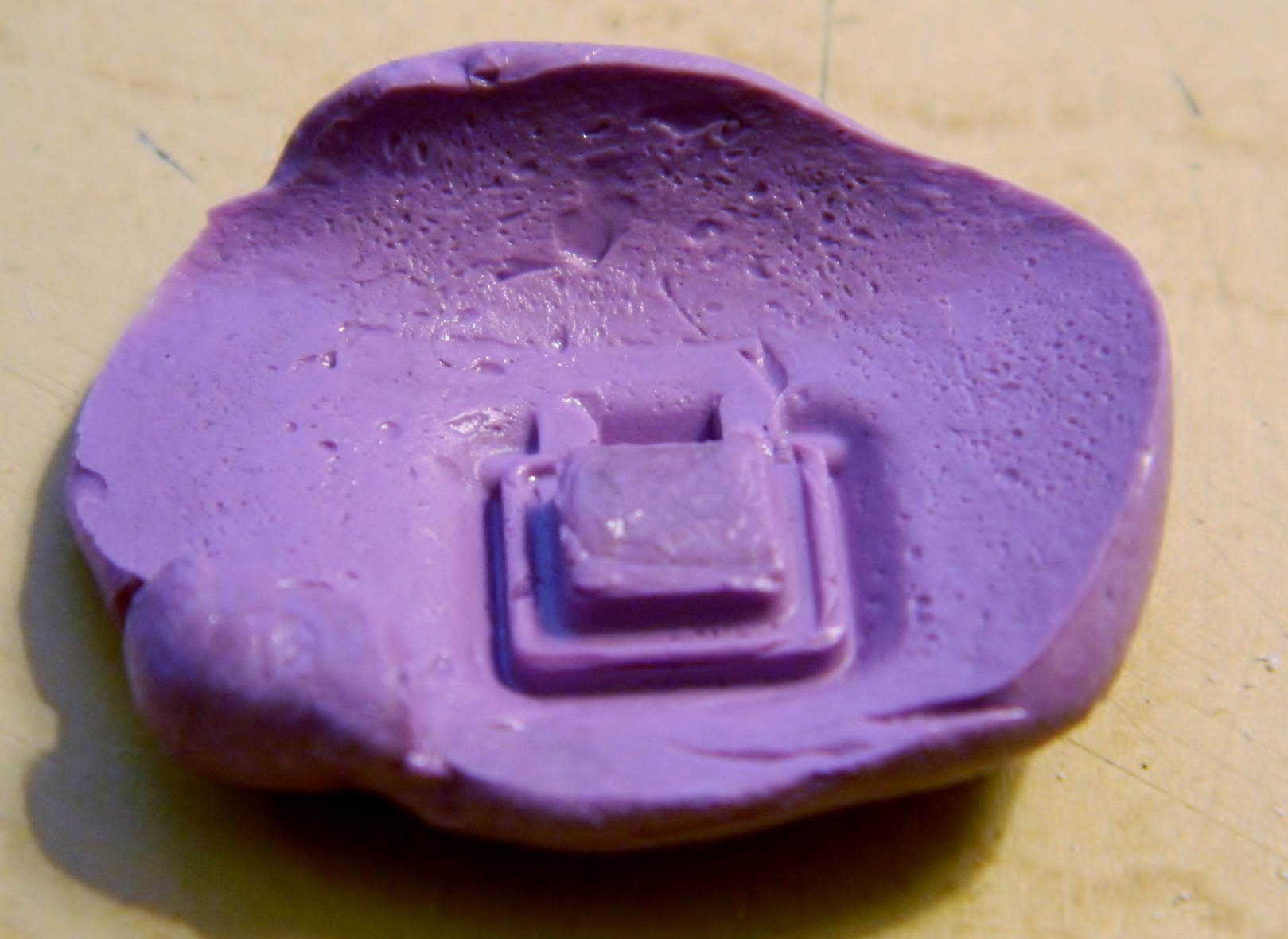

The next day I popped this out of the mold. In doing this, I discovered that if I move the putty around once it’s in place, it creates all these bubbles, but since this is a test, I didn’t much care:

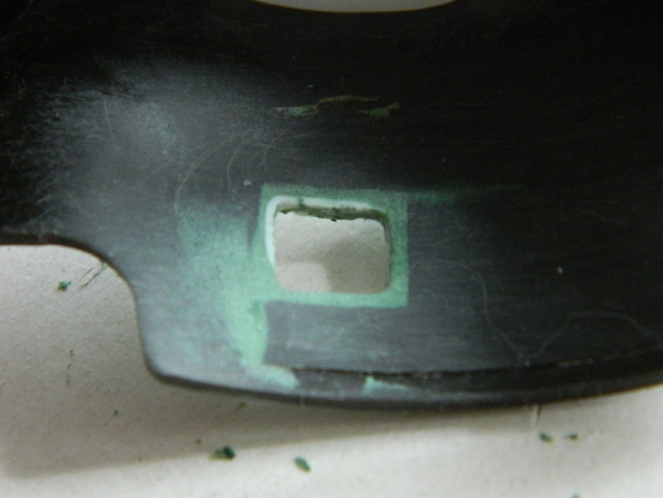
Since this is an experiment, I used the spare turret from my mule and cut the hole for the port out, trimmed the back and edges of the molded piece, applied it, and puttied the edges:

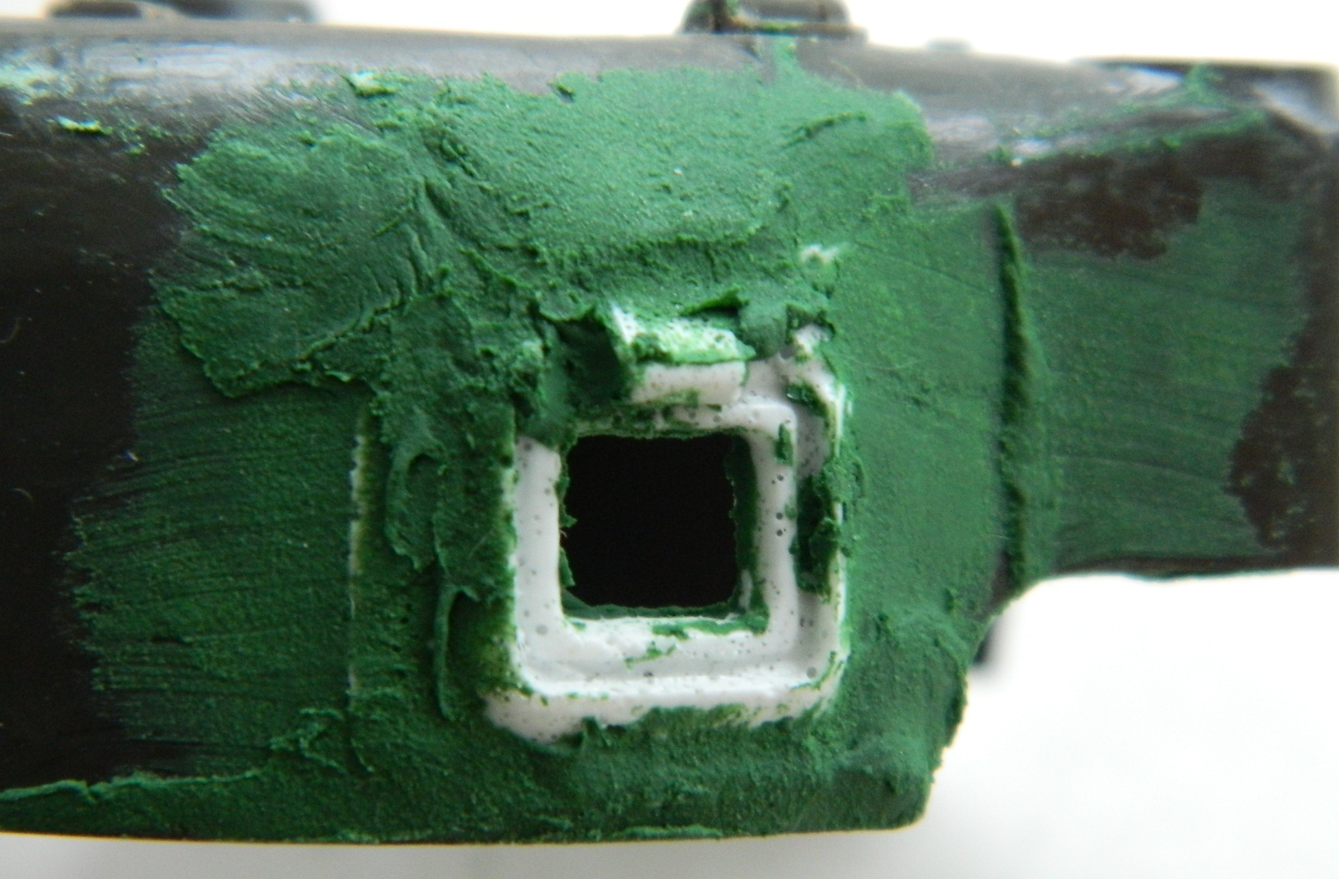

After letting the putty cure overnight, trimmed it, and was quite pleased with the results:
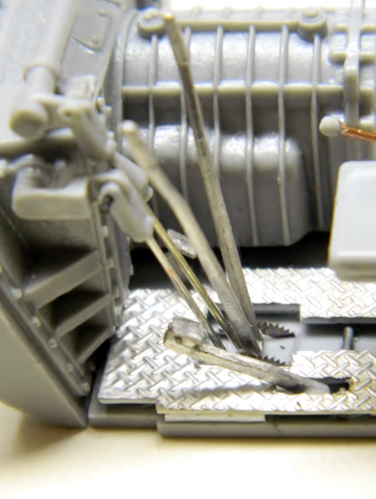
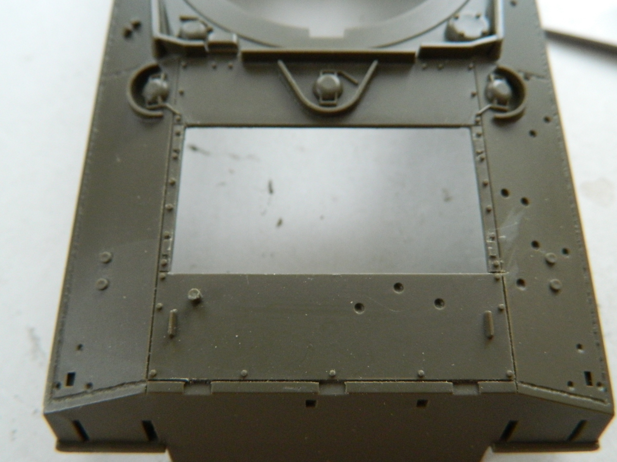
I’m putting an engine in this model and I want the engine covers to be open. The kit’s are molded in place so I have to cut out the opening. First, drill a hole, then take a small saw and cut to the inside of the opening:

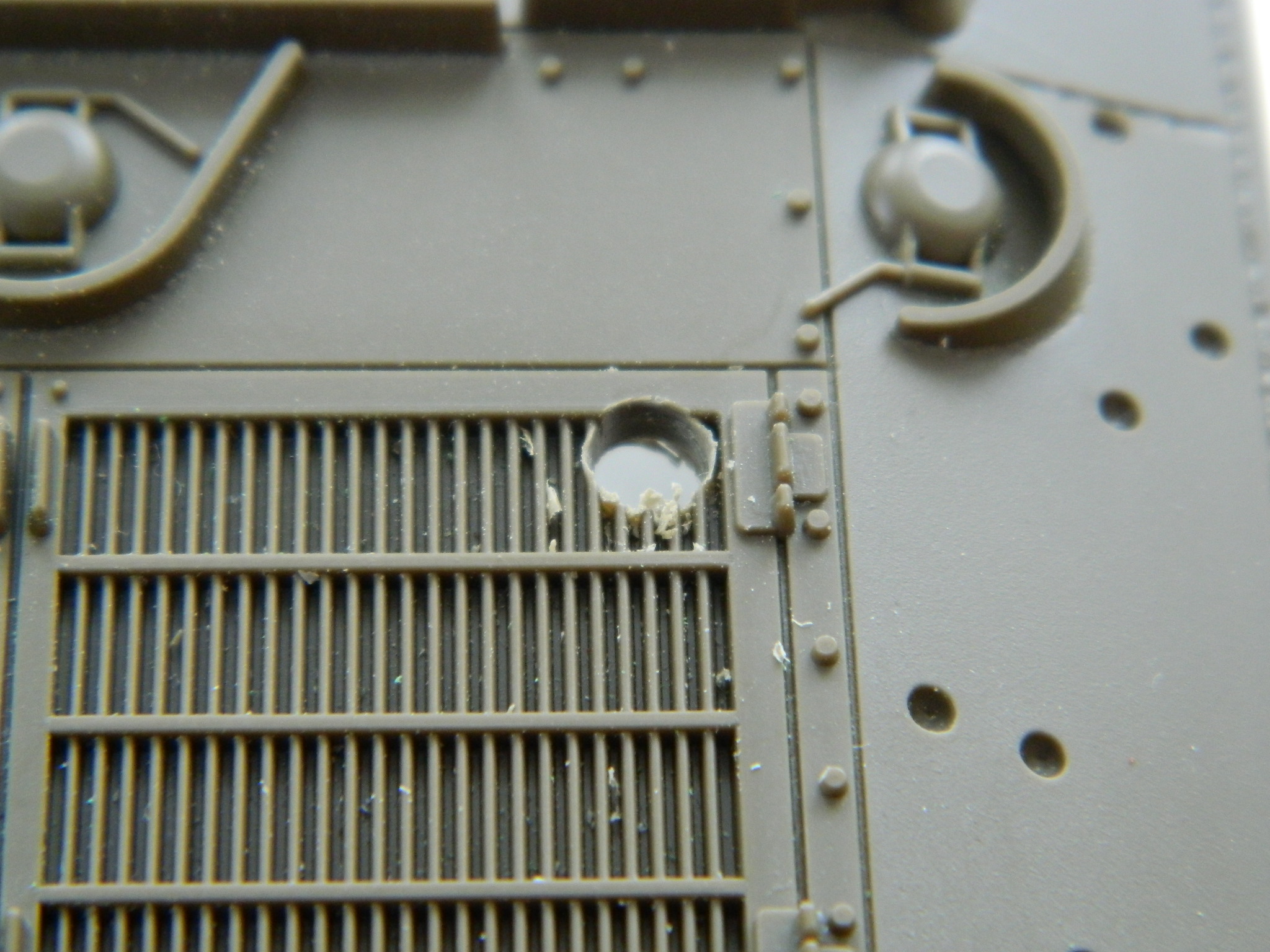

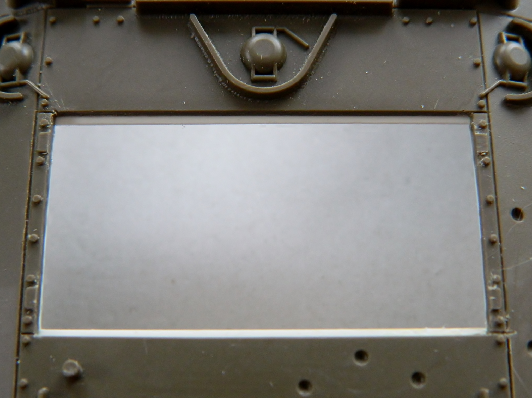
With the opening roughed in, the edges have to be cleaned up and the lip that the covers rest on (and are bolted to) has to be put in:
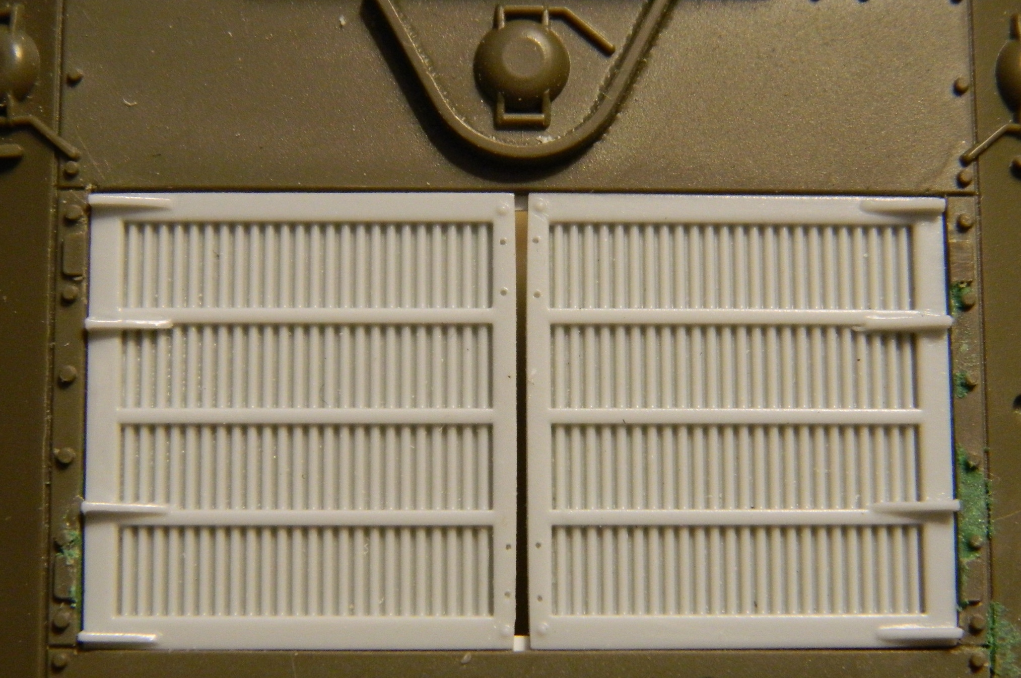
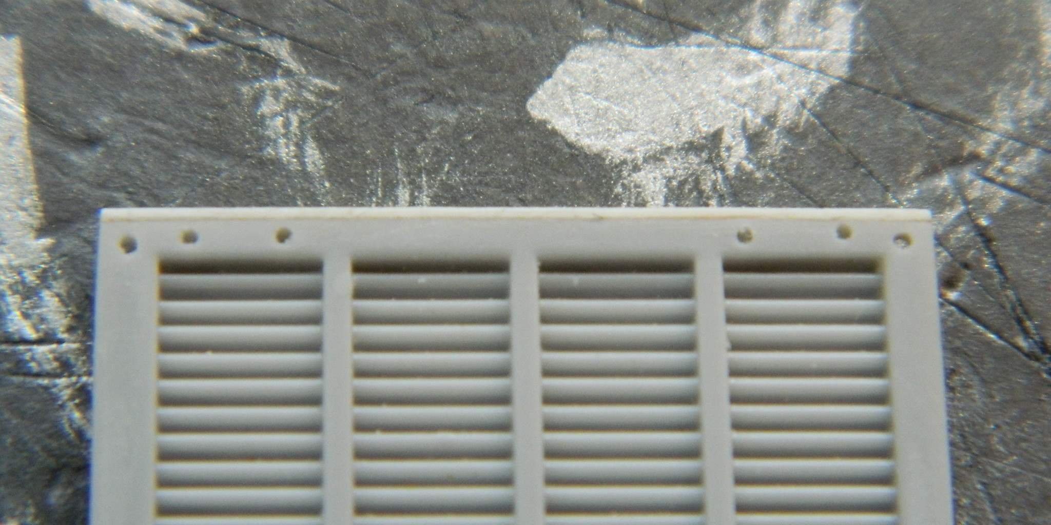
I wanted to do the engine covers next. I had initially thought to use the pair that came with the engine set but they’re inaccurate. Back to the Interwebs! I found a great manufacturer (Tiger Model Design, TMD) who does beautiful resin castings for the engine covers (and many other things as I discovered through the course of this build):

The parts need to be modified because they (accurately!) replicate a post-WWII M4A3’s covers, but that was done relatively easily. The height of the covers fits but I had to add plastic strip to the edges, as well as remove the hinge-strengthening fins and make WWII-style hinges:


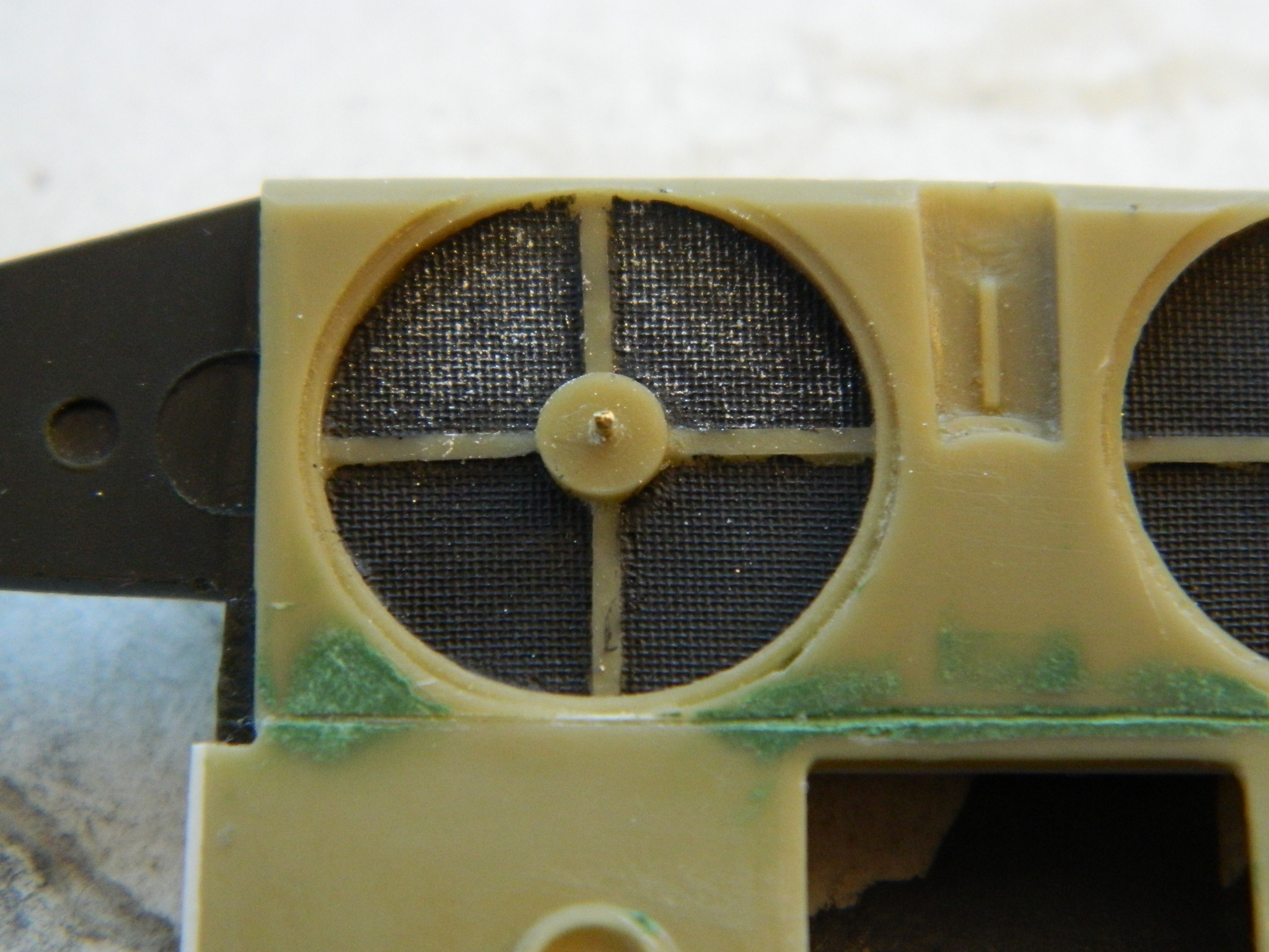
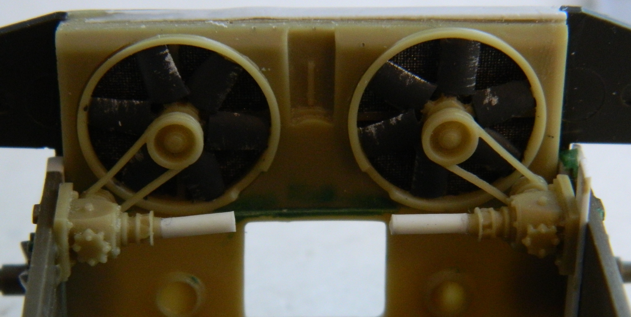
Back into the engine bay, before I put them together permanently, I needed to be able to get under the fans to paint the radiator faces as well as the fans themselves:

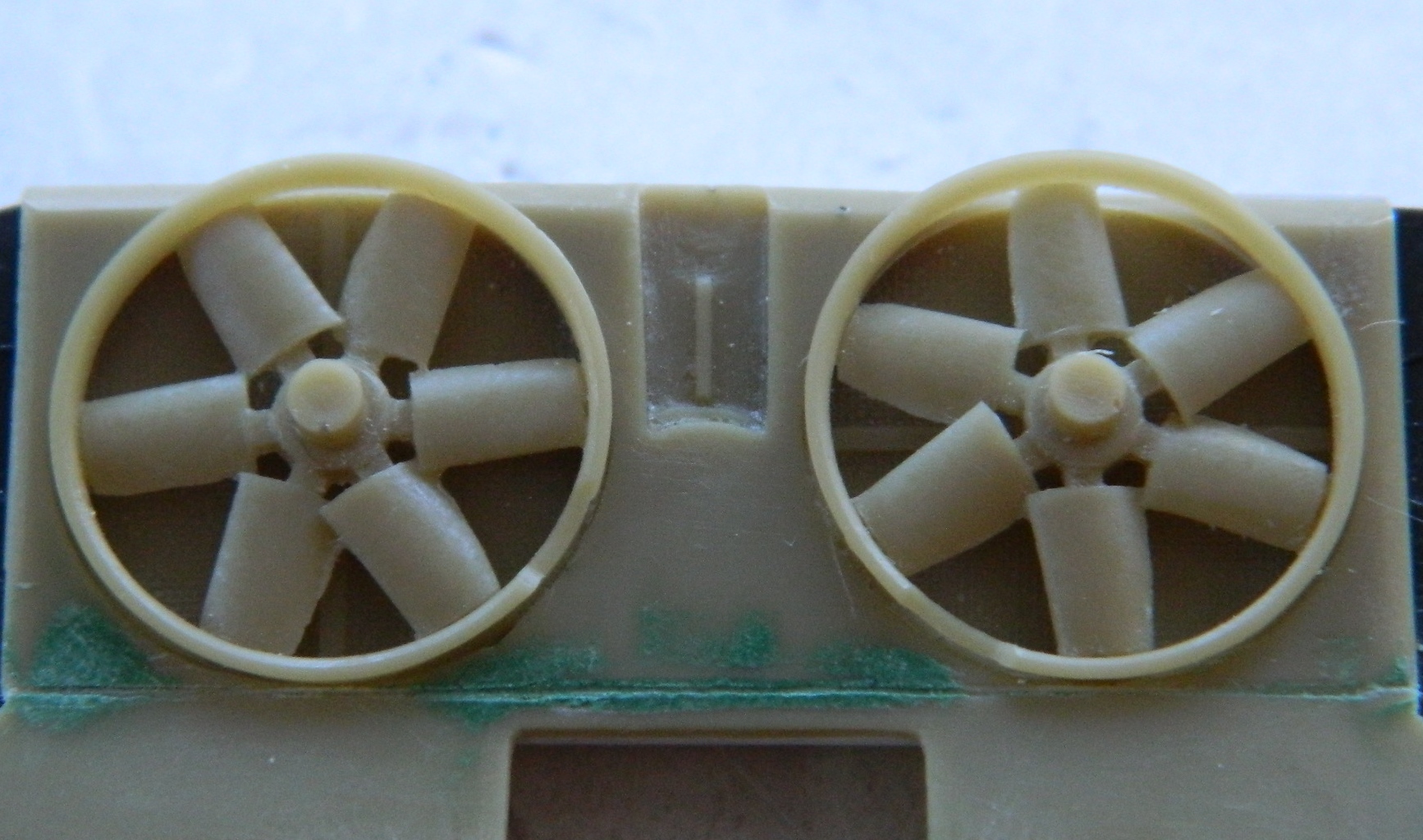
I hit the radiator faces with paint first and dry-brushed aluminum paint over the faces to bring out the detail (like anyone’s ever going to see them):
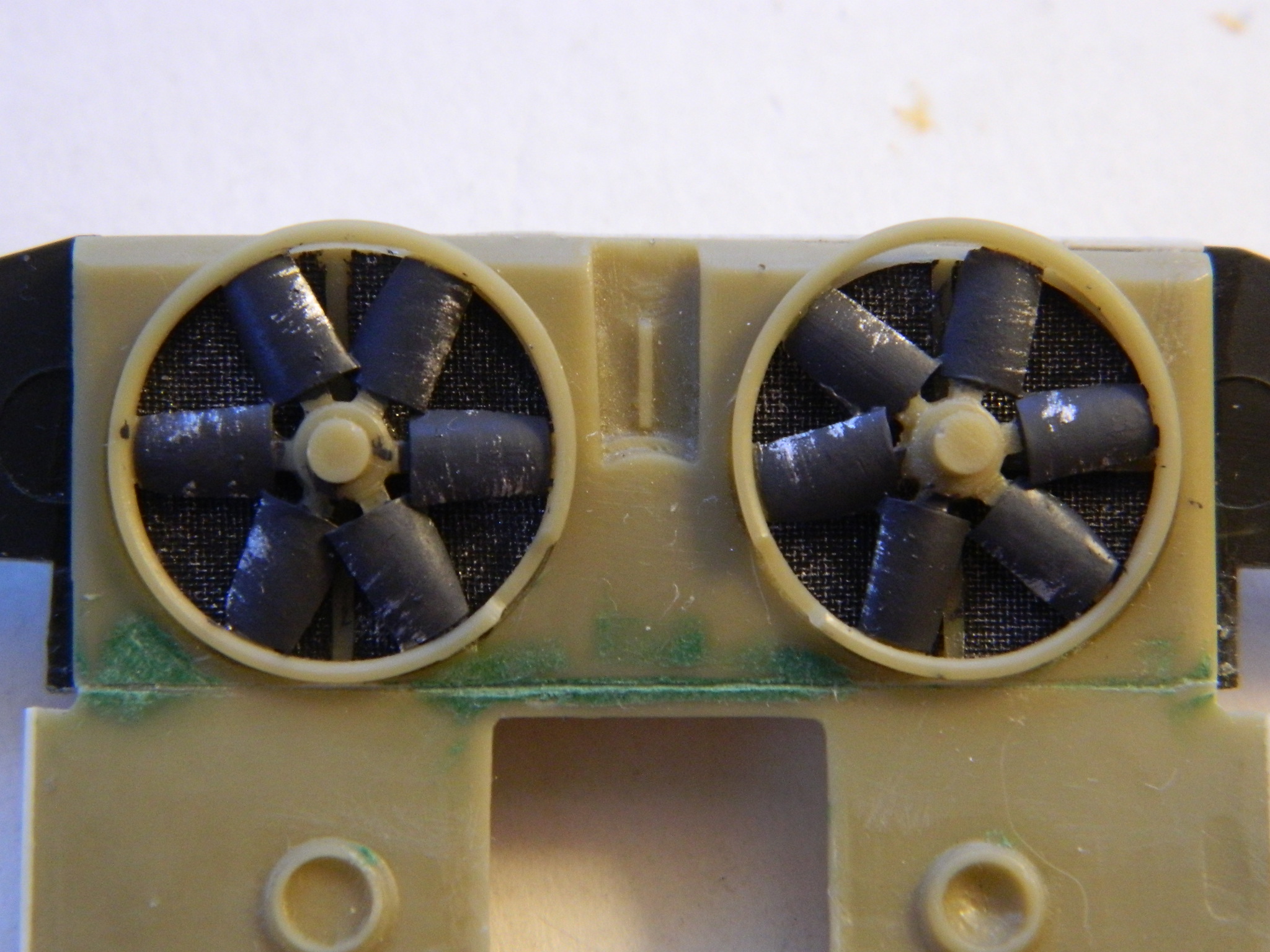
Then I painted the fan blades and added wear to the leading edges with more aluminum paint:
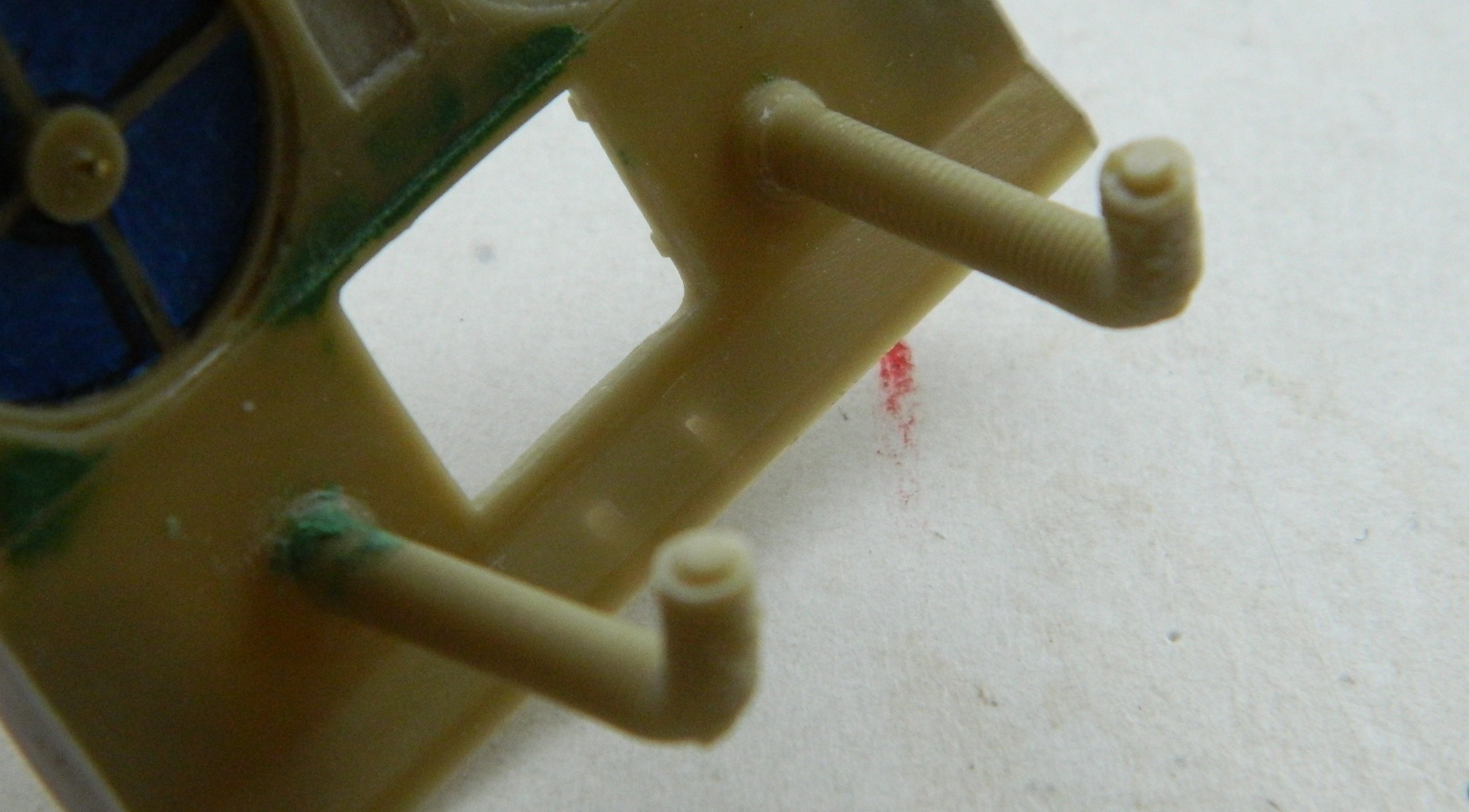
Since I knew I was going to be masking the radiators and fan blades, I wanted to fit the other things into the engine bay first. I didn’t know how far off the thickness of the tape would throw things so before I started masking, I had to get parts ready to dry-fit and the easiest way I knew was to drill out holes add pins, and since the fans were driven by PTO (power take off) units, I wanted to add styrene rod to make sure I had enough length to replicate that:


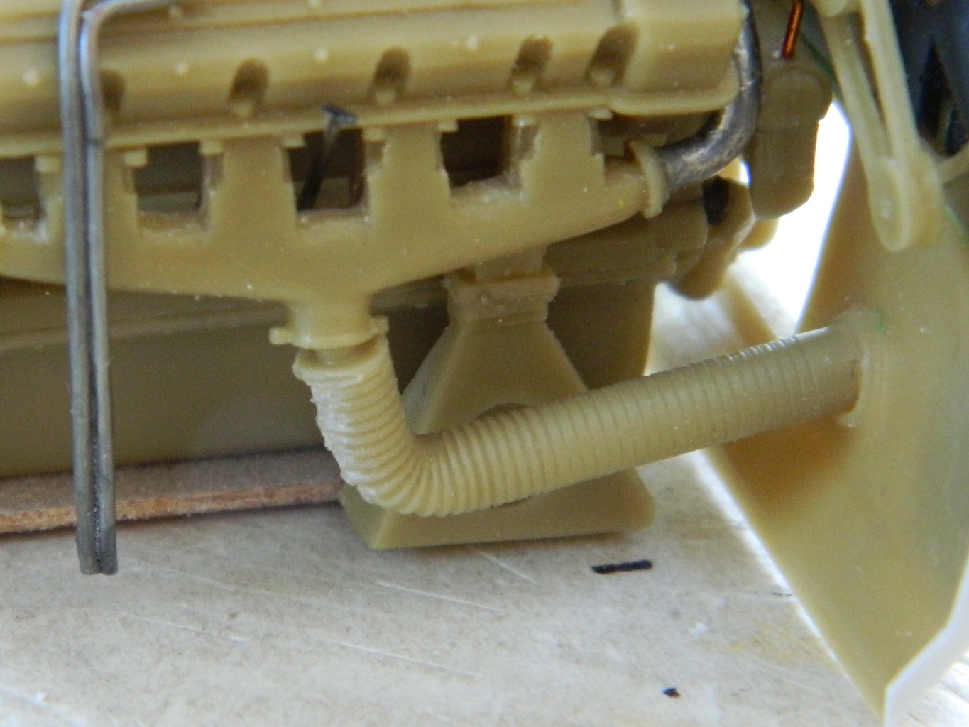
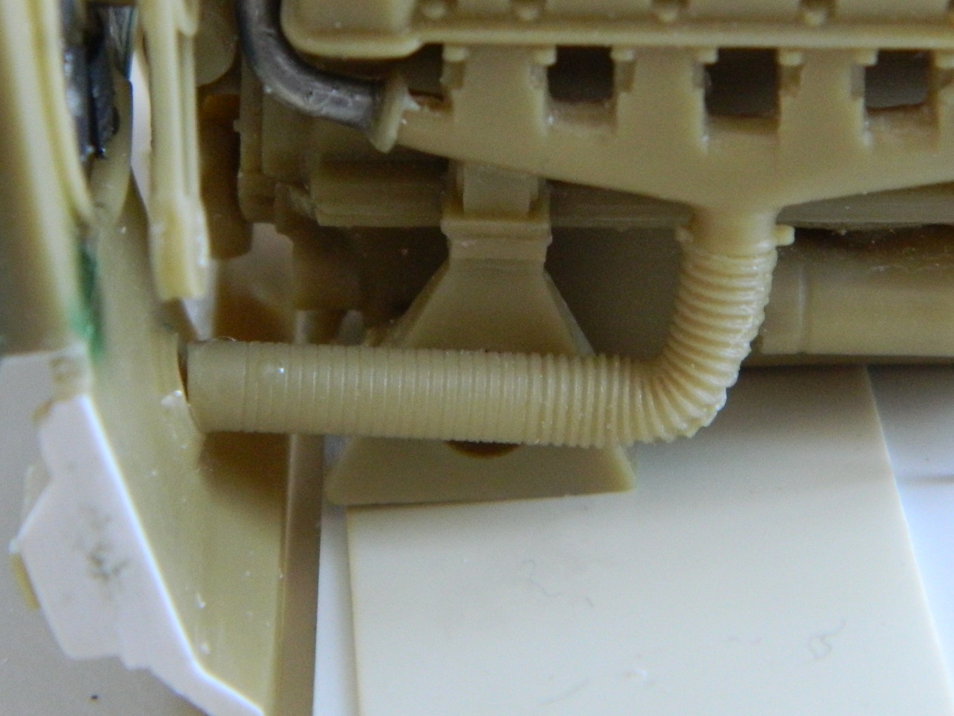
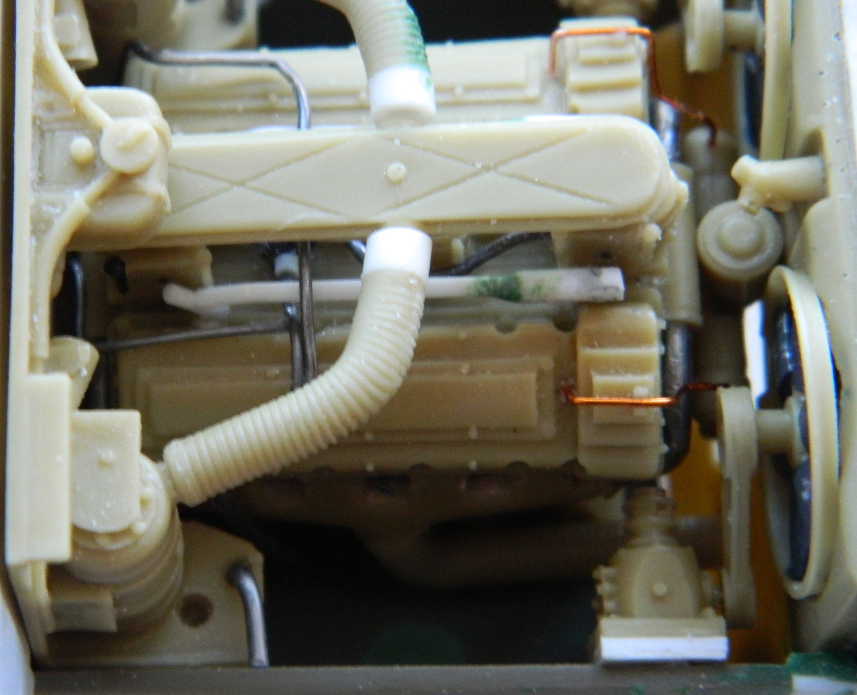
Then came the tedious process of dry-fitting (wherein once again I lamented the fact that I only have two hands; three or four would have made this so much easier). Once I had the engine placed in position, I added the ducts that route air from the air cleaners to the plenum:
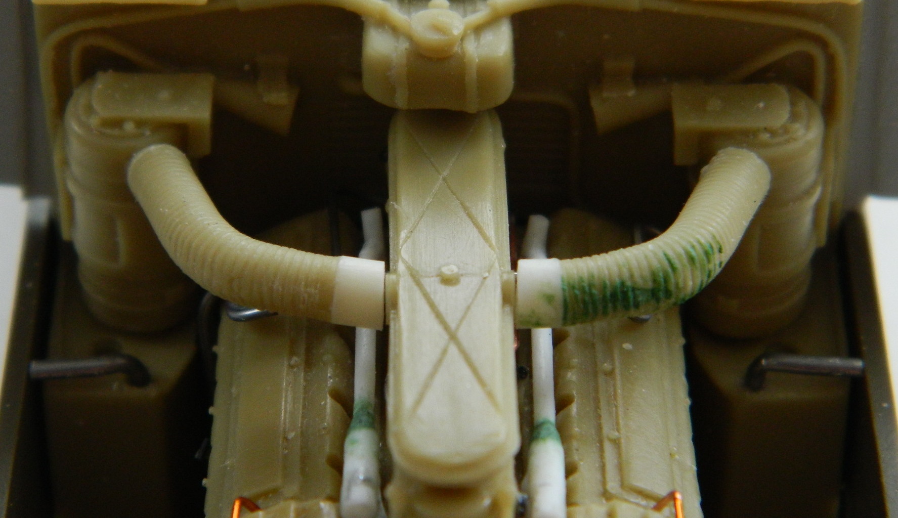
With those in place to establish the relatively exact engine location (and obviating the need for one extra hand), I dry-fit the PTO units, fan blades, and belt/pulleys into place:
Putting the engine back in showed me that I needed very little of the styrene rod I’d added so those got trimmed and I adjusted the mounts for the PTO units so that they would align with both the fans and the engine (you can see what that needed by the thickness of the added styrene between the right PTO and the hull as opposed to what the left PTO needed):

The I put the engine in to see how it all fit:

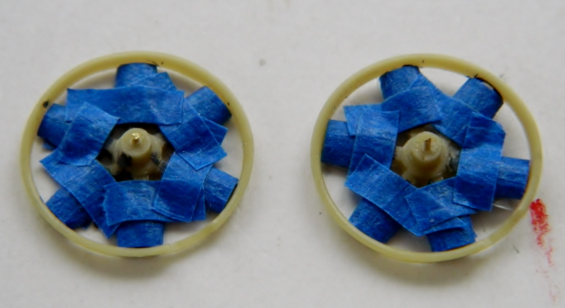
Since that worked well enough, time to mask the fan blades and radiator faces:

Then I attached the exhaust pipes to the rear bulkhead. I’m not 100% satisfied with the alignment but with the way things are packed into the engine bay, the gaps will not show: