P-51 (Accurate Miniatures) Build #15 – Adventures in Forensic Modeling…Picking Up Where I Left Off
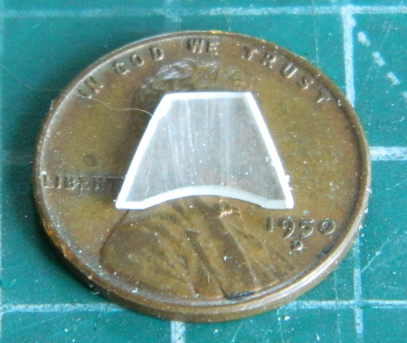
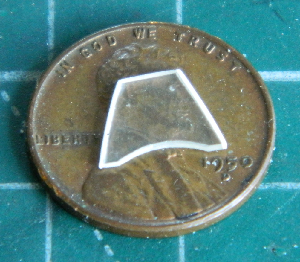
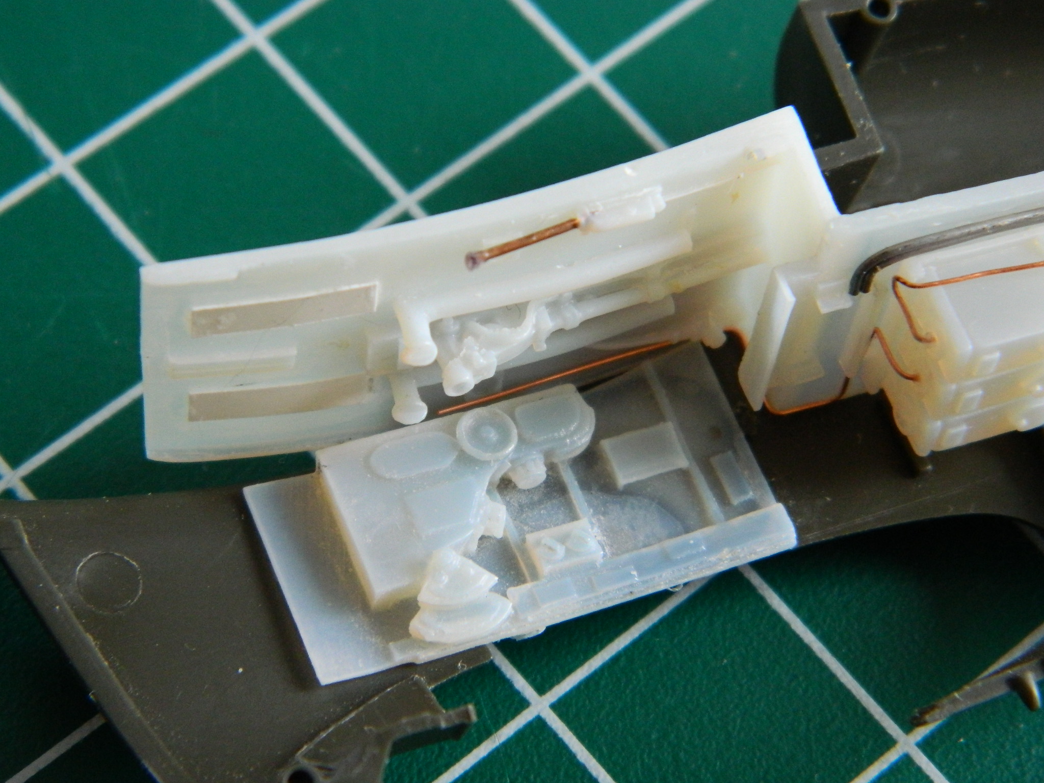
I have now discovered that “for now” can mean four years because that’s how long it’s been since I worked on this one. I knew when last I screwed this thing up what I needed to do to fix it…well…most of what I needed to fix it. At the time I crashed this build, I didn’t have my lathe, so I hunted eBay to acquire another Accurate Miniatures P-51. Took a couple of months of sporadic checking but I did find one and shortly it was on the shelf along with the box the aborted build was on. The big stumbling block for me, though, was how to do landing lights, or more accurately, landing lights with covers. Another problem was after I dropped the model (rarely does the build any good) and broke the propeller mount off, I tried to insert a short section of brass tubing to accept the brass post I planned on adding to the prop. The mistake there was in using a Dremel tool with a cutting disc. Cutting discs make heat. Heating a brass tube socketed into a plastic surround can (and in my case did) get you something like this:

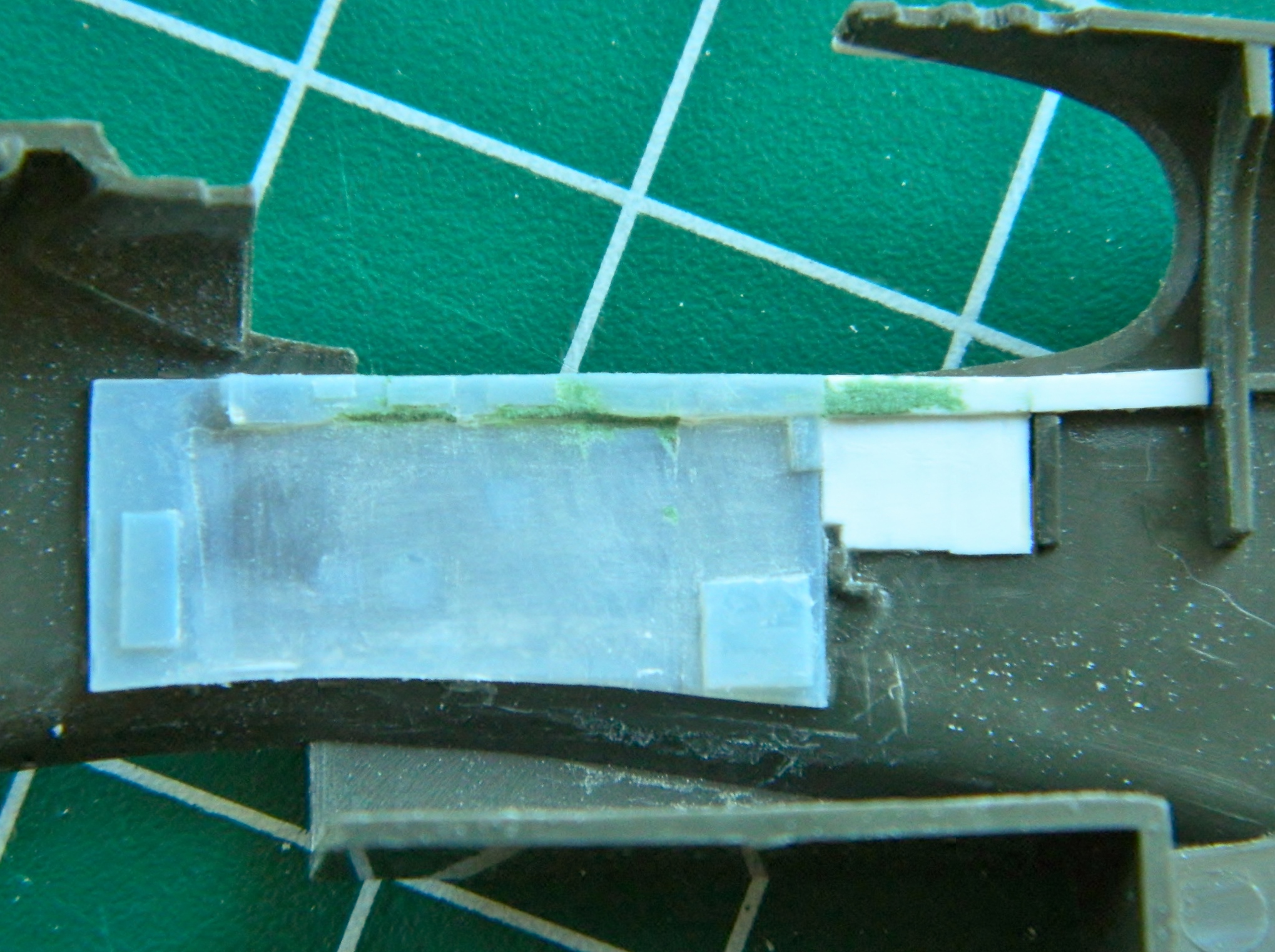
While I was looking the model over, I noticed that the watch crystal adhesive I’d tried had failed. I don’t know how long it actually held the film with the gauge faces on it in place, but it was evidently not four years. Look under the instrument panel to the left of center:
Yeah…they’re obviously not supposed to be there. I needed to get behind that panel and the only way I could think of was to cut the nose off and I made the cut(s) along panel lines :

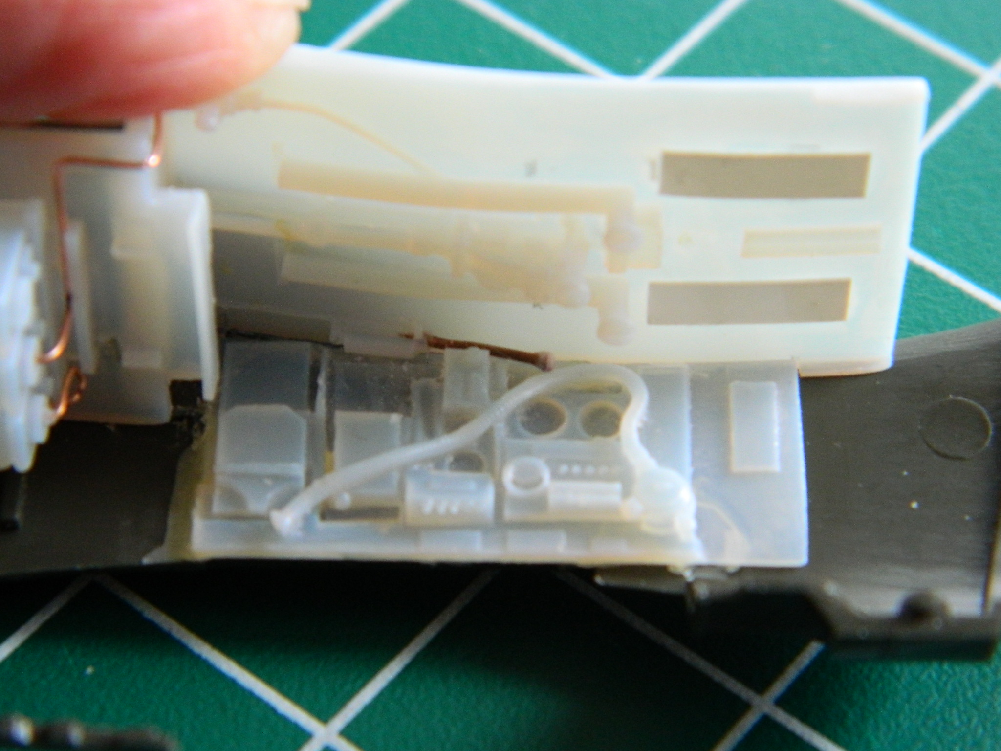
With the nose off, I encountered a couple of features I’d forgotten about; the tubular spacer I’d inserted to help the wings fit tighter to the fuselage and the forward bulkhead of the AM resin part:

I drilled a hole large enough to insert the tip of a saw blade into and gained access to the rear of the instrument panel:

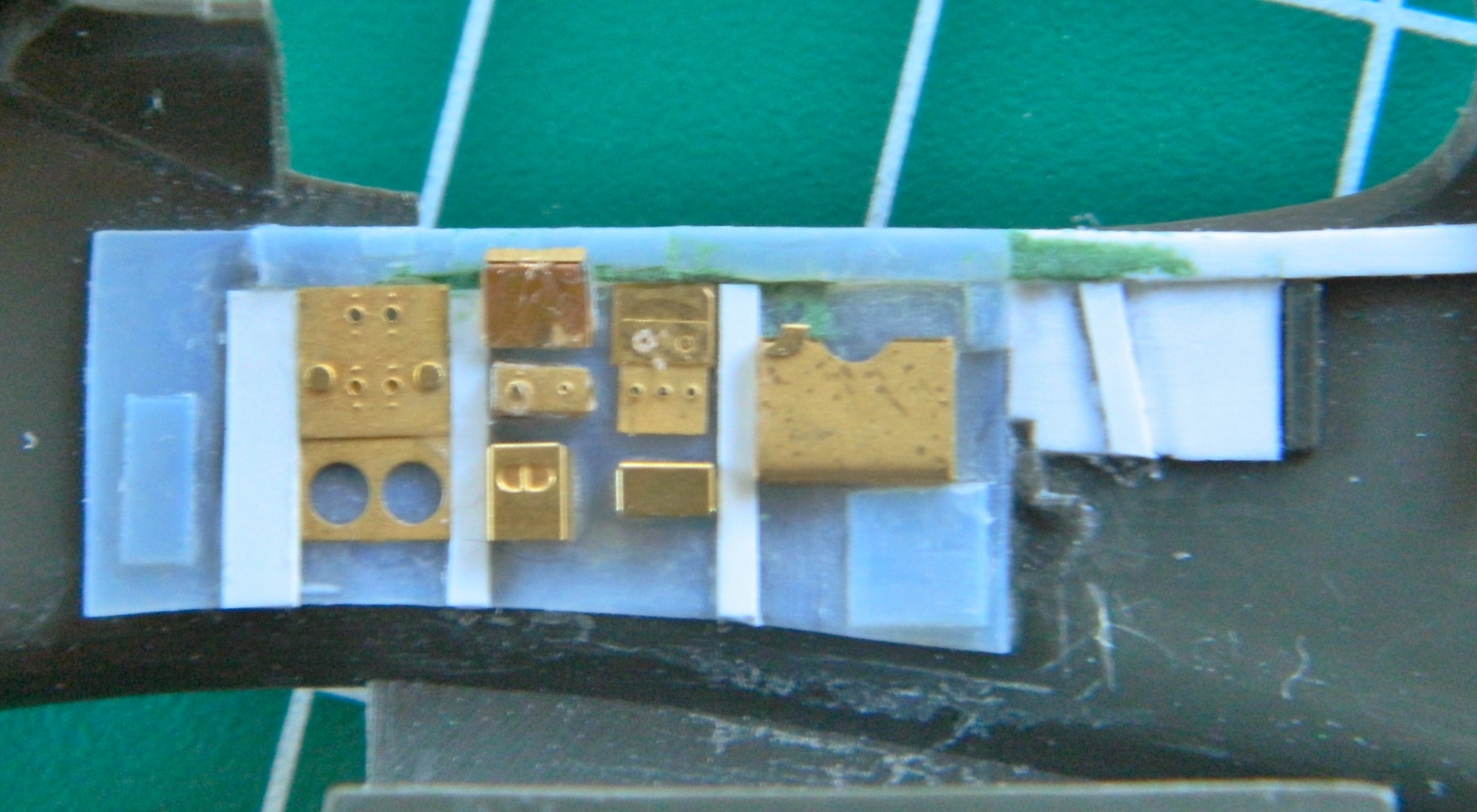
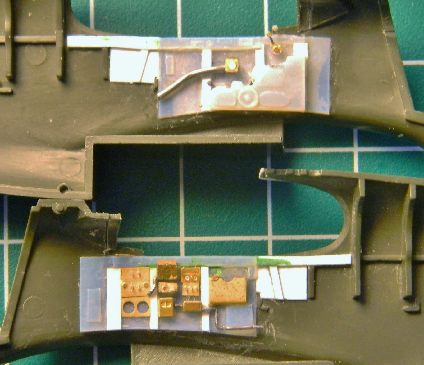
There are many benefits to using acrylic paints. After four years, I could just dab the back-painted gauge faces with a cotton swab soaked in denatured alcohol and the white paint just came off. That enabled me to line things up nicely. Having discovered that the watch crystal cement is not what I want to use again for this task, I drilled a couple of holes in the film so that I could wick small drops of superglue in between the film and the panel. Then I reapplied white paint to the backs of the gauge faces:

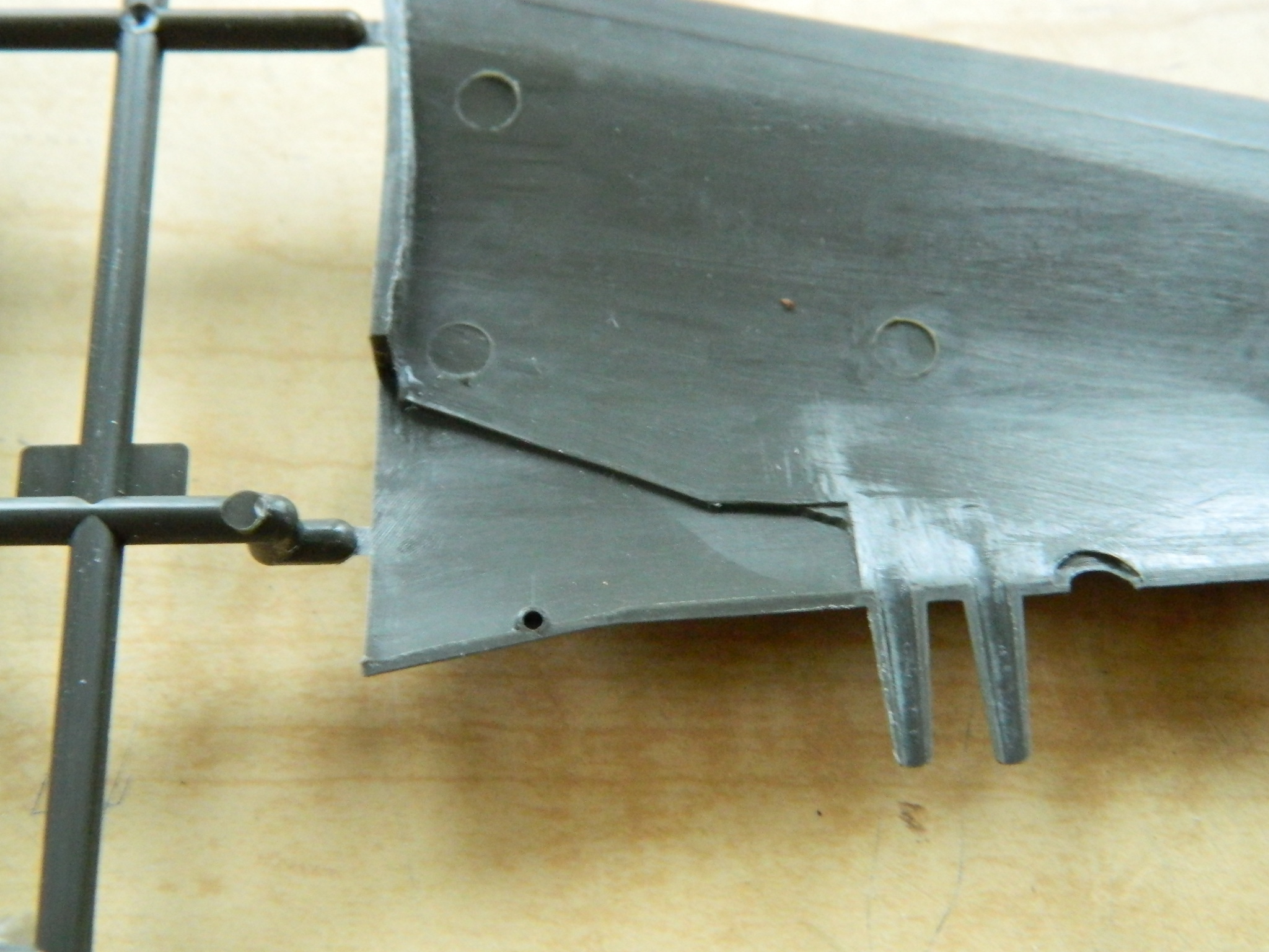
I opened the second P-51 kit, assembled the wing, and then cut the cannon shroud from it. Then I (gladly) cut the shroud that I’d melted the tip of off:

Then it was a simple matter (and I certainly appreciated that novelty!) to graft the new shroud in place, shim it into alignment, and then glue the hell out of it:

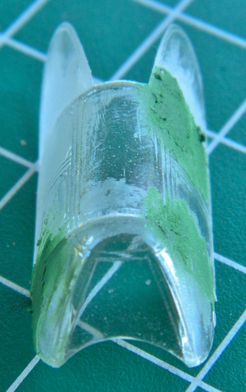
The kerf was puttied and over the course of a weekend, managed to get this build back on track (the vacuformed canopy is taped in place to protect the cockpit…particularly the gunsight) (which I managed to snap off anyway, lose completely, and made a replacement for):

Well…that was easy…
The only modeling magazine I subscribe to (and recommend) is FineScale Modeler. A GREAT many of my modeling techniques have been pulled directly from their pages (the colorful invective is of my own creation). In the October 2020 issue they have an article on page 18, “Age Before Beauty.” The article is about taking one type of aircraft, the F8F-1B Bearcat, and using two kits to compare those kits. The interesting thing is that one kit is 40 years old (Hawk) and the other is modern (Hobbyboss). The intent is to see what is required to bring an old kit up to modern standards. (A LOT!)
I told you that to tell you this…
One of the things the builder did to the old Hawk kit was to replace the wing-mounted landing lights. (I was going to say, “Just like I did,” only he was successful and didn’t melt anything.) That was just the information I needed to pull this kit off the shelf and get on with it, which I did as soon as the build I was working on at the time was completed in.
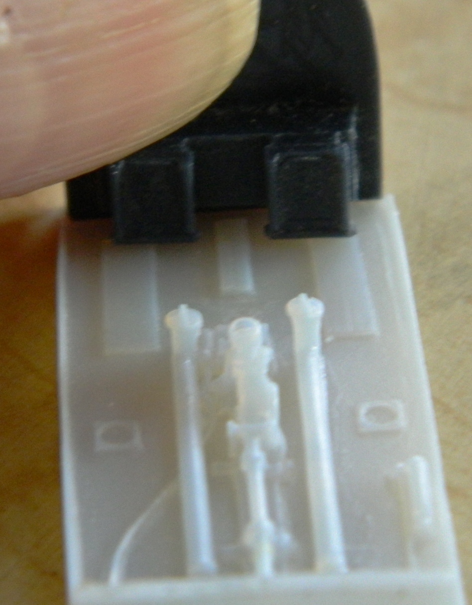
The idea was to take a solid piece of clear acrylic, cut/shape/polish it to shape and then drill the back of it slightly to replicate the light itself and then paint it silver or chrome…and that’s what I did:


With all that done, the back of it was painted black, it was then glued into place (a bit prematurely, as I will point out shortly), and then filed/sanded/polished into an adequate representation of a landing light behind a clear cover:
Shortly after that was glued…PERMANENTLY…into place, I decided that I could have used a slightly larger drill. But I didn’t, can’t get the part out, and had to do the other one the same way. Even so, it was a magnitude better than what I’d tried originally. (“Originally” didn’t work, this way did. I’d say that’s better.) I used the spare kit’s landing light sections as a template to make the masks for the landing light. Where the tape is stays clear, what’s around it gets painted:

The area behind the acrylic insert, being round, doesn’t quite match up with the upper wing surface. I added plastic and sanded it all smooth, scribing in the necessary panel lines.
While I was at the site of past trauma, I decided to stay there and get the shrouds ready for the cannon barrel analogs. One of the thing I’d noticed is that most of the cannon-armed P-51s had barrels that free-floated inside their shrouds. I drilled away the mounting collars (the white plastic) I’d originally installed, then used the same diameter styrene rod to stuff into the holes of the shrouds:
After cutting the rod flush with the shroud, I used the rod to push the stub inside the shroud in a wee bit and then glued it. Once I treated all four shrouds that way, I drilled a hole in each to slide the barrels through. The result was nicely floating cannon barrels (the tape on the nose in the lower photo is to protect it from the putty I added when I corrected the panel lines under the nose of the fuselage):


Having done that, I was now completely recovered from prior oh-gawd-dammits and the “forensic” part of this build was done. On to new stuff!
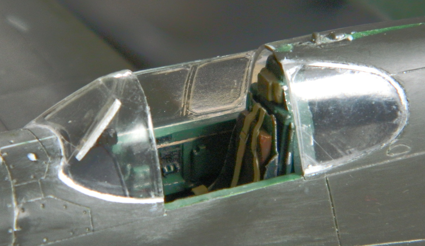
“New stuff” started with the canopy. One thing I noticed with some of the earlier P-51s (and others…the P-38 did it the same way) was that the armored glass wasn’t a part of the canopy but instead mounted on brackets behind the front canopy section. To do that I used the canopy I’d tried to vacuform a canopy over and cut the section out between the two framing sections:

With that section cut out, I used .010″ (.254mm) styrene scraps to form the mounting frame and then sanded and polished it, resulting in a to-scale thickness “armored” panel:
Now all I had to do was to glue the armored glass inside the canopy and then add all these delicate and thin parts to the fuselage:

“All I had to do,” he says as if it were simple. ::giggles::
My original intent was to use the vacuformed rear canopy sections. After carefully trimming them and noticing how FREAKING THIN they are (which is actually the point to vacuforming to begin with), I realized that I had an incredibly small contact area for adhesives (and yes…I did realize that I would have that same problem with the rest of the vacuformed canopy…but I’d bridge that cross once I got to it). Once again my original intent was discarded and I tried something else. Instead of the vacuformed parts, I used the kit parts. The fit wasn’t the best, which is why I tried using putty to make up the difference (the white stuff around the top of the part):

Then I figured I’d deal with the very thin canopy and see what I had to do to get that part glued into place (other than virgin sacrifice…at my age I don’t have the time to find one of those). I used superglue and it worked, after a fashion (no frosting), resulting in the application of more putty:

While the glue was curing, I turned my attention to the propeller and spinner. The kit’s propeller blades aren’t at all representative of what the P-51 used; they’re more like ungainly canoe paddles. Instead I used a set of props I bought for an A-20G Havoc I have in queue. I took molds of the props/hubs and cast resin copies to use. The P-51’s prop was 10’6″ (3.2m) long and the A-20’s was 11’3″ (3.43m) so I shortened them slightly:
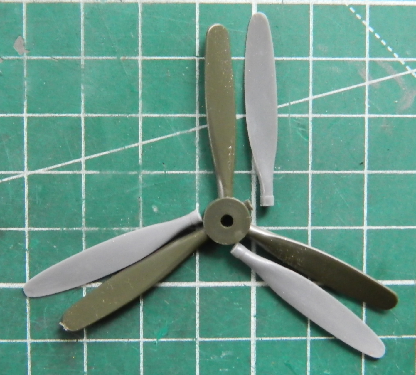
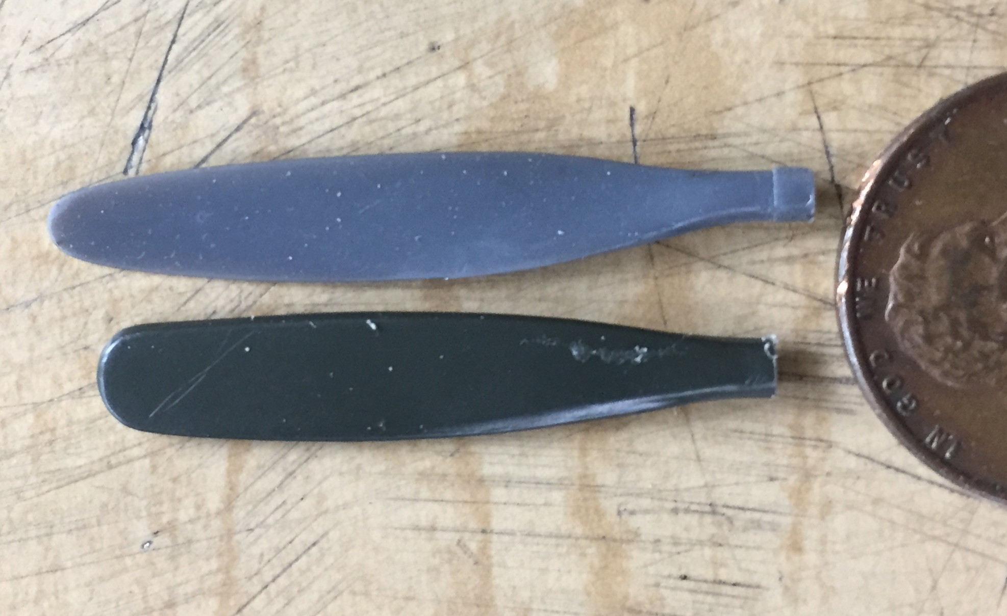
I cut the kit’s paddles…er…props from the mount and added pins to glue the resin prop blades more securely:
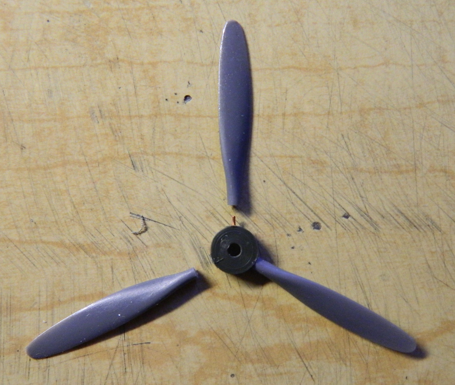

And what’s a propeller without a spinner? (Oh, I dunno…a drag, maybe?) While cutting the parts from the sprues, I cut just a wee bit too closely and flat-spotted both the base and nose of the spinner, which required me to add styrene scraps:

Perfection still eludes me.
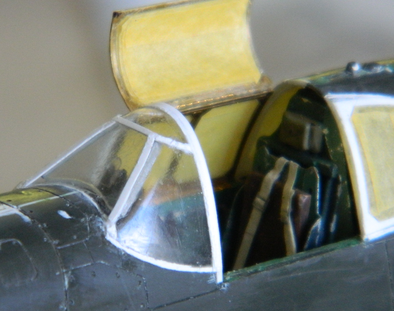
With the glued canopy now cured, I opened the parts box and realized that yes…perfections ELUDES ME. There are PE frames in there that I wanted to use! Well, okay, then…let’s get these things to work. Shortly after my initial attempt to fit them, I realized that once again my “error” saved me from AN ERROR. Or if not having saved me from AN ERROR, the “error” actually saved me a metric tonne of hassle. The vacuformed canopy (courtesy of Squadron Products) is very thin. Trying to bend PE parts to conform to them without deforming them would have been OH such a joy. It was enough of a “joy” with the bottom of the canopy glued into place, offering much more rigidity than would have otherwise been possible had I not “erred.”
I started bending, fitting, and bending some more. (Repeat those steps a lot so I don’t have to write them out.) Eventually I got the right side frame in place (totally ignoring…by intent…how much fun I was going to have getting that thing painted):

Then I had to form the outside frame, which also included the top of the canopy that swung open to allow the pilot to get in and out of the kite, as well as the left side of the canopy that hinged downward to enable such access:
In my attempt to add the inside PE frame to the hinged top I realized that the result of two PE frames and the plastic between them would result in something far too thick. Bugger that. I didn’t add the inside frame, figuring to replicate it with paint. Some detail would be lost but it struck me as an adequate trade-off to a part that was ridiculously thick. To avoid the same problem with the open side canopy, I used some .005″ (.127mm) thick acetate. Still a bit thicker than I would prefer but it falls within the 90-95% tolerance.
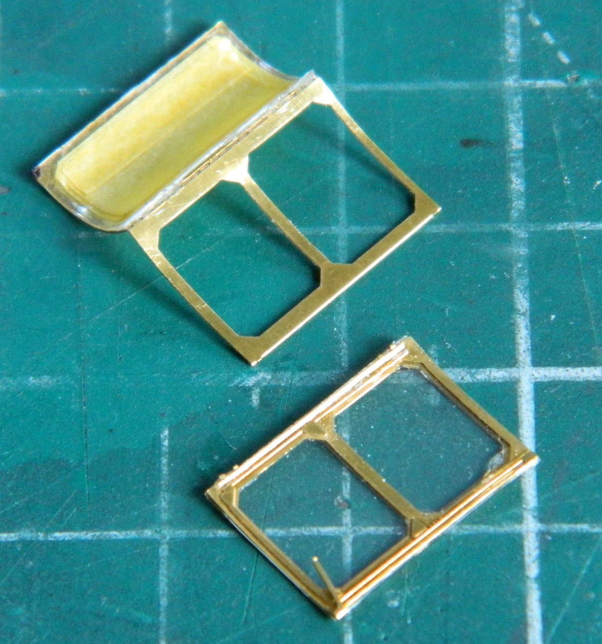
The rear sides of the canopy also has PE frames:

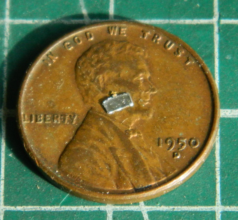
Though not especially large, these frames are not the smallest part I’ve used. They’re also not the smallest part I’ve dropped. My ability to find this PE part that I dropped indicated to me that SOMEwhere on the floor of my shop is an inter-dimensional portal. After I dropped it, I spent the next hour crawling around on the floor, moving everything movable (my drawer units are on wheels enabling that to be accomplished easily) out of the way and, as I sit here typing this, have STILL not found the [EXPLETIVE DELETED] thing. And while I’m on that topic…
Four years ago when I was constructing the cockpit from AM resin parts, I discovered that the joystick had a bubble in it just below the grip of the joystick. I discovered this by snapping the Damned Thing off. That part, also, eluded recovery. Lost and gone. Alas. Then four years passed. During that time the shop floor has been swept (relatively frequent occurrence) and vacuumed (I do that at the end of every build). Four years. Frequent sweeping and not infrequent vacuuming. While I was down there looking for another part I’d dropped (I’m old and feeble…I drop things) (so far not me, but I’m sure that’s coming), guess what my frail and ancient eyes did spy.
The grip of the joystick!
Go figya, because I certainly can’t…because the Damned Thing was right out in the open and not in or under anything else. (And don’t go there because I DO know how to vacuum and sweep!)
Moving on.
Since that PE part is in some undiscovered dimension elsewhere, I used the remaining PE part as the template to copy another one. That’s why the photo above has an aluminum background, because my first attempt was to use thick aluminum from a disposable baking pan…which created many more problems that it would have solved:
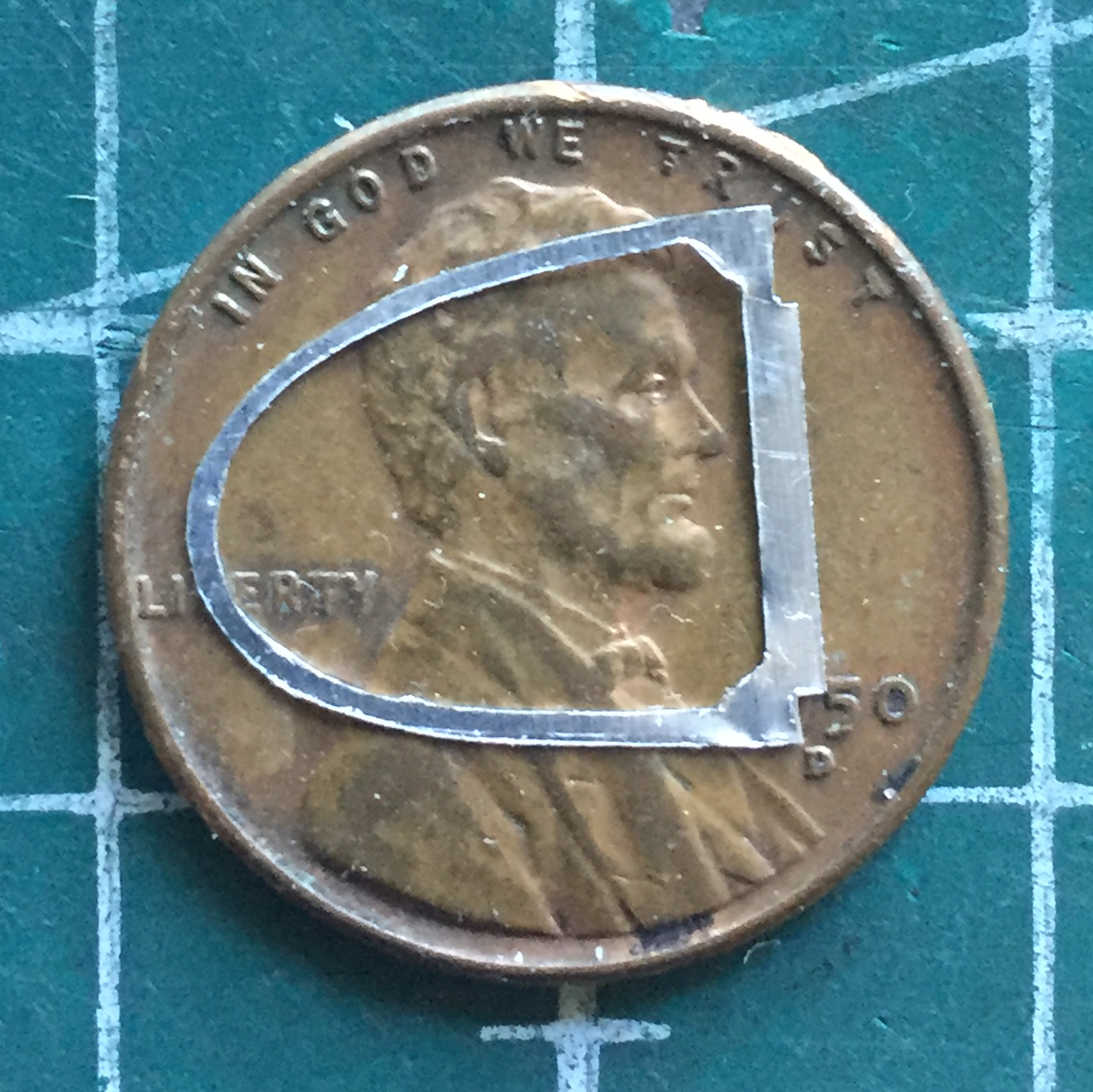
Yeah…go ahead an trim that for size and smooth edges! I’ll sit and watch. I tossed it and used .005″ (.127mm) styrene instead (yeah….005″ (.127mm) styrene was a better choice, that’s how difficult it would be for me to clean up the aluminum copy):

I added the frames to the rear canopy sections and fared them into the fuselage with putty:

While the putty was curing, I went back to diddling with the PE canopy frames. This time I got smart (or more likely less dumb) and didn’t add these parts before I masked them (A quick word about Tamiya’s masking tape. It’s great. It’s thin and a little stretchy, enabling it to be curved around shapes, and isn’t highly tacky, enabling it to be removed without taking off what it’s stuck to. End commercial.):
Having gotten those parts masked, I added the side/top framework to the canopy. With those in place, I started building the framework for the front canopy using .005″ (.127mm) scrap:


With the canopy frame built it was time to mask it, and this is where I found a pothole in the path of my build. Just the wrong amount of pressure (with a very sharp knife) at just the wrong point of the canopy exceeded the gripping strength of the superglue and the whole fornicating thing popped off:

I was so thrilled.
And then I looked a bit closer at it. Y’know…I’d totally overlooked the fact that the INside of white plastic strips is also white. But the INside of the P-51’s canopy framing wasn’t white. It was the same color green as the rest of the cockpit. Well, well, well. Dodged another one! It will be SO MUCH EASIER to mask and paint the inside of the canopy with it off the fuselage than it would be on the fuselage.
Yep…sure was:

It’s true. Sometimes it’s better to be lucky rather than good (assumes the person who’s still working on “good”).
Before the canopy can go back on, it needed to be painted the green of the cockpit. While I was at it, I filed/sanded down the added chunks of styrene to the spinner, used white glue to hold the parts together, and painted both parts:

I glued the canopy back onto the fuselage and then turned to the PE rear-view mirror. I put a tiny drop of superglue onto the PE part and then pressed standard (aka, thin) aluminum foil into the depression and then trimmed the foil and painted it semi-gloss black before adding it to the inside of the canopy:

The canopy was glued back onto the fuselage and gaps around the edge was puttied:

I usually don’t remove the masking tape until after painting has been done but this time I removed it to be certain that I’d trimmed the putty back far enough…and it looks like I had:

A friend of mine’s father used to be a dentist. He retired, moved away, and my friend was getting his house ready for the market. Any modeler will become emotionally erect when the phrase, “dental tools” is mentioned. Yes…they’re that handy. And all of the hand tools my friend passed on to me are that handy. But the really BIG SCORE was this little beauty:

It’s a Buffalo Model #15 electric grinder. Zero to 25K RPM controlled by a foot switch. It also came with a lot of really small burrs (grinding tips). Some of which are REALLY SMALL.

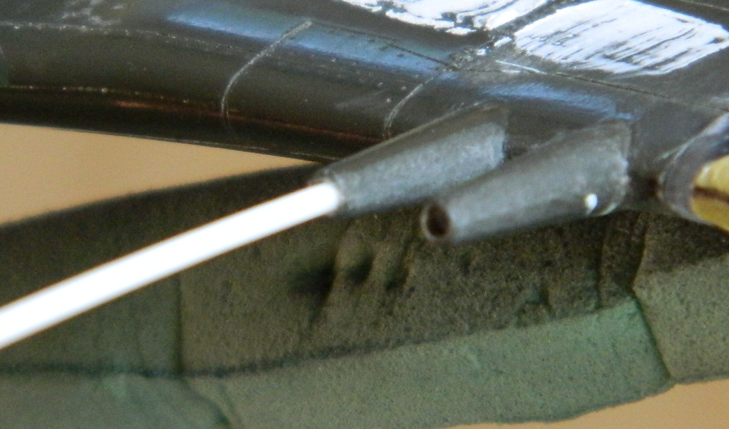
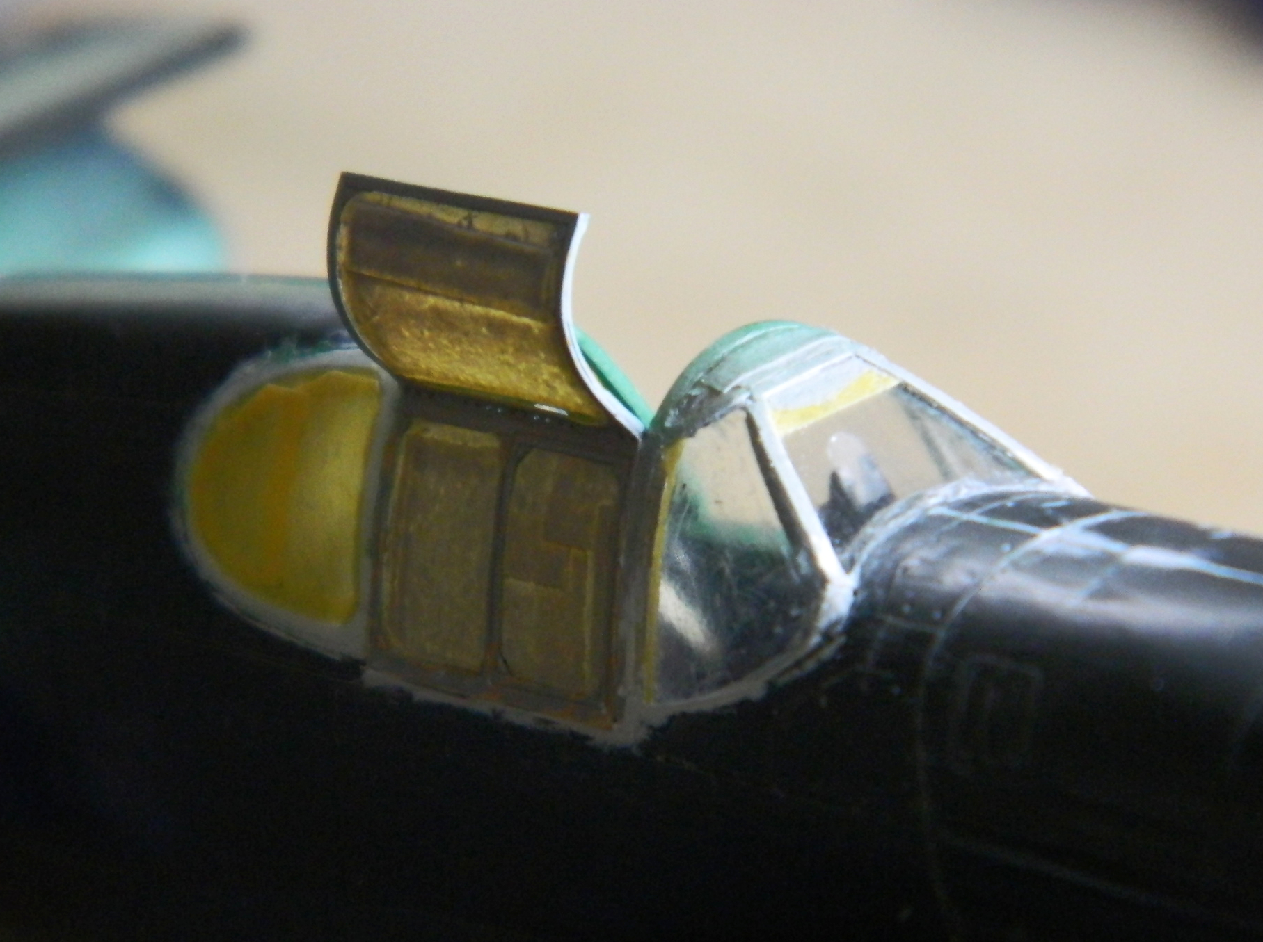
Those aren’t even the smallest burrs. What that lovely little machine allows me to do are things like this:

In 1994 when this kit was copyrighted, slide-molds weren’t used in making model kits (I don’t know if slide-molds even existed at the time). That means the outlets for the exhaust tips, which is what those two parts are, were molded solid. If you look closely at the strip of tips to the upper right, you can see where I used that LOVELY little machine and the smallest burr to depress the surface of the exhaust tips. They’ll look great once they’re painted!
P-51 (Accurate Miniatures) Build #6 – Fixing Cockpit Detail Errors, Canopy Fitting
One of these days I sincerely hope and intend to take my own advice. That advice is, refer to references often. Doing so has the potential to save me self-created work.
After doing the modifications (I thought were) necessary to the cockpit’s sides, I actually did check my references. Had I done so before gluing the side panels in, it may have been easier to do the other modifications I needed to do. And what modifications were those? Well, nothing really major, just taking the details that are accurate for a P-51B out and putting in the ones that are more accurate for a P-51. In short, don’t take the printing on the package as factual. Verlinden’s details are good for a P-51B but are mostly inaccurate for a P-51. That meant I had to remove the incorrect details and put in the ones that are more accurate:

I used the Polish PE set (which were the easiest set I’ve yet worked with; the really small parts were scored to make the bends easy):


The holes in the various panels and boxes in the photo are places where there are toggle switches. I rummaged around in my wire inventory and found the correctly sized wire (.006″) (.0152mm) to replicate the toggles. The real trick was getting them aligned and glued in. Much colorful invective later, I got them glued in, let them sit overnight, and then trimmed them to length the next day (with much more colorful invective required), and then added the electrical conduits:


I’m also going to be vacuforming a new canopy from .010″ (.254mm) clear styrene. I’m going to need a form to pull the clear plastic down around and I’ve previously had good results using the kit-supplied canopy as my form. In order to do that, I’ve found it works better if I fit the kit-supplied canopy better than is allowed for in the kit. So the various parts were dry-fit first to get an idea of what needed to be fixed:


Then after determining where the fit needed to be adjusted, I added .010″ (.254mm) sheet styrene behind the front canopy section, to the fuselage, and then determined which areas of the canopy itself needed to be filled for a smooth transition between sections and added putty:


With all that taken care of and set aside for when it’s time to paint, I decided it’s time to address that instrument panel. I have a few ideas…some of which may actually work.
P-51 (Accurate Miniatures) Build #5 – Cockpit Work
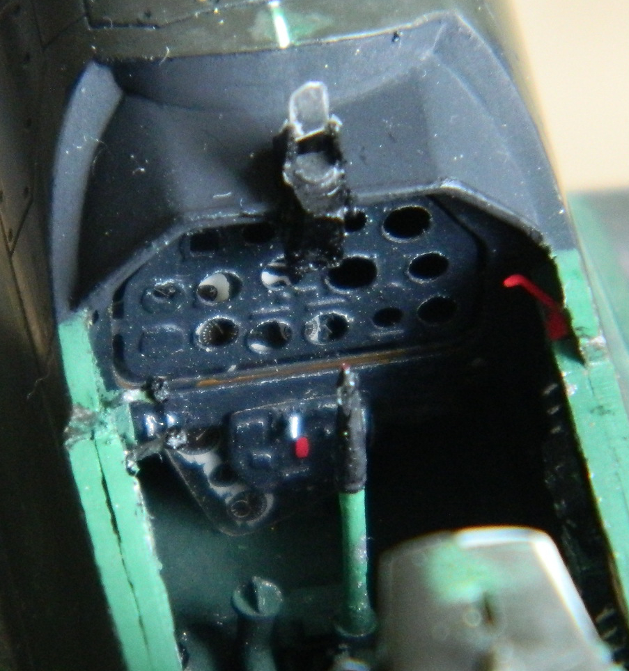
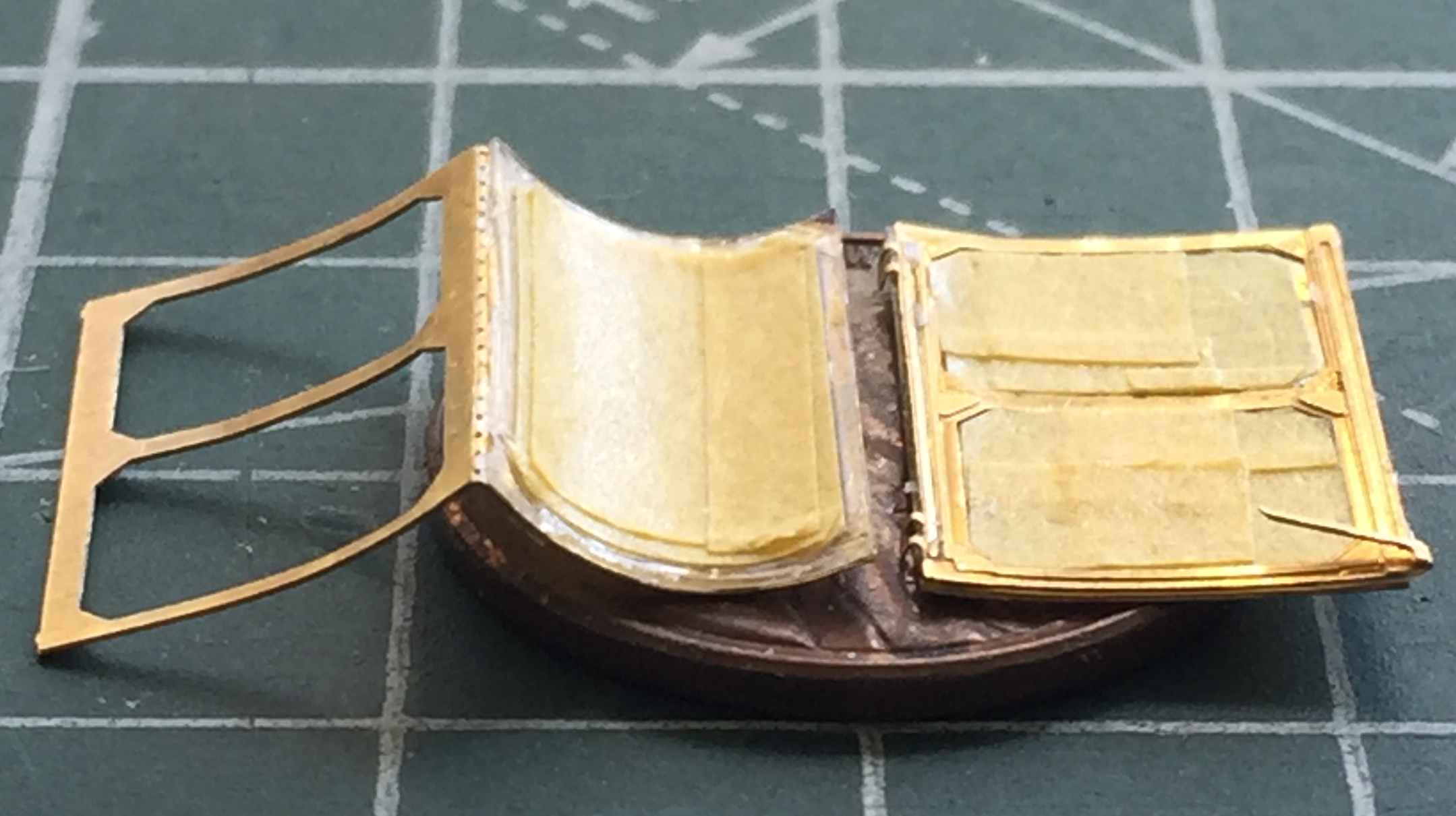
My initial intention was to scratch-build the instrument panel. I don’t think either the kit-supplied part or the resin AM replacement offered anywhere near enough (accurate) details. There’s a company in Poland, Elementy Do Waloryzacii Modeli Plastikowiych, that makes a very nice photo-etched detail set for the P-51A (#S48-111). Since the differences between the P-51 and the P-51A cockpits are minor (no bomb/drop tank release, as the P-51 had provisions for neither), I picked up a set. I like PE parts for some things and I don’t like them for other things. The determining factor is the thickness of the metal being used. Sometimes it’s spot-on, other times it’s too thin. But since it was my intention to scratch-build the instrument panel anyway (using the Waldron instrument faces), I didn’t really think that would be a consideration. I used the PE part as the template and used my (freshly sharpened) panel scriber to cut closely around the PE template to create the panel’s frame and inner panel (they’re separate on Mustangs). To keep things from moving around, I taped the PE sheet to the plastic sheet and had at it:


Waldron’s punch and die set was a bit more than my wallet would bear, but Micro-Mark offered a cheaper set which I bought. I checked as closely as these 66-year-old eyes would allow seeing if the punch sizes worked with the gauge diameters (and they do) and then started punching holes in the plastic panel:

“I didn’t really think” is the operative phrase, there. The short-form of the problem is scale thicknesses. I came up just short of the room required to make an accurate representation of the locations of the gauges. I needed a few scale inches more width than reality provided to get everything to fit that I didn’t have. I briefly considered thinning the plastic on the fuselage sides to get those inches back and then realized that that would be SUBSTANTIALLY more hassle than simply using the PE set’s instrument panels (and beautifully reproduced gauge faces) and create other problems that I needed like I need a third buttock.
In looking at the brass and gauges, I realized I have no idea how to paint it and put it all together, the problem is in masking the three freakin’ tiny gauges that are located in the panel’s outer frame. Well, while (what’s left of) my brain worked on that conundrum, I started work on getting the rest of the cockpit to play well with each other and fit inside the fuselage.
As stated in other places, I use copper wire, solder, and lead wool to replicate lines and conduits. Copper wire, solder, and certainly lead wool are not provided in straight sections, which are much more handy to work with and are often required to be straight. So how do I get from this:

To this:
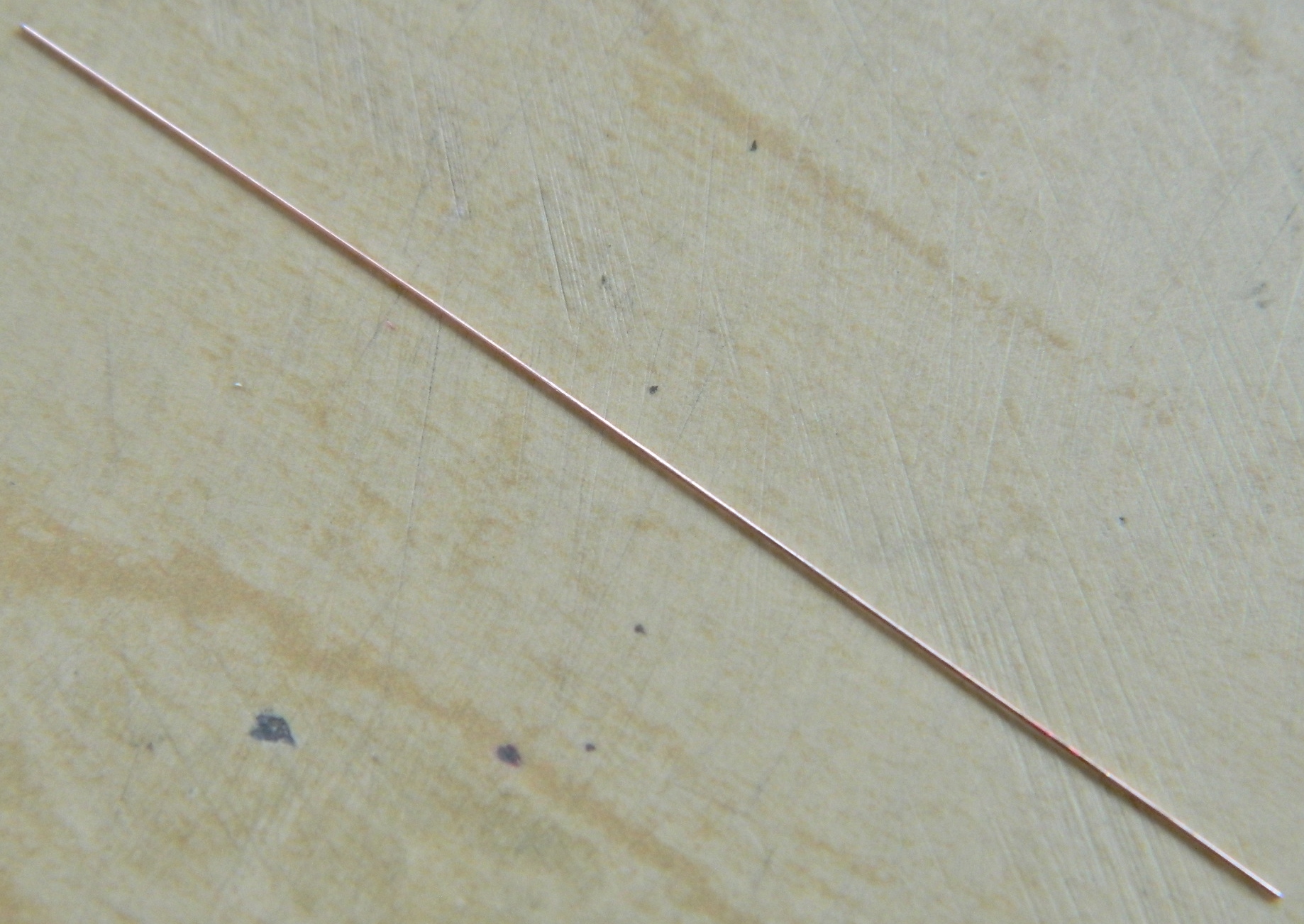
By using these. The clear pieces are old acrylic covers to welding masks (the type that doesn’t auto-darken). I tease the wire, solder, lead wool, into roughly a straight section, then I lay the piece I need straightened on one surface (usually the acrylic plates for solder and lead wool and the metal plates for copper, though I will use the metal plates for thick solder and the acrylic plates for thin copper) and gently rub the two plates against each other:

Once I had the copper wire straight, I folded it in half and twisted it:


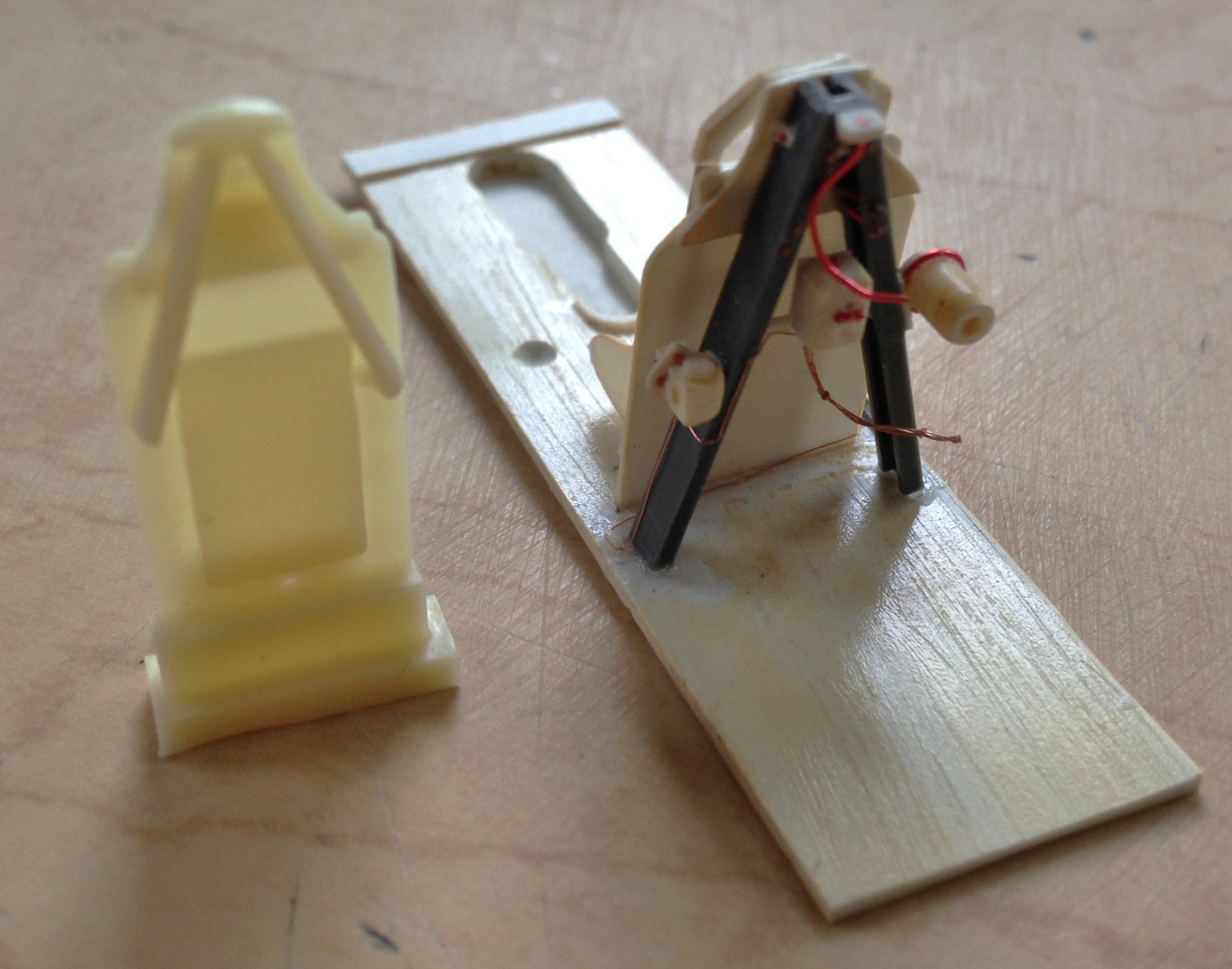
The lower radio shelf was glued to the floor section and conduits of copper wire and solder were added as well as adding the rollover brace to the armor plate, adding the junction box (the white part) to the brace, and then wiring them up:
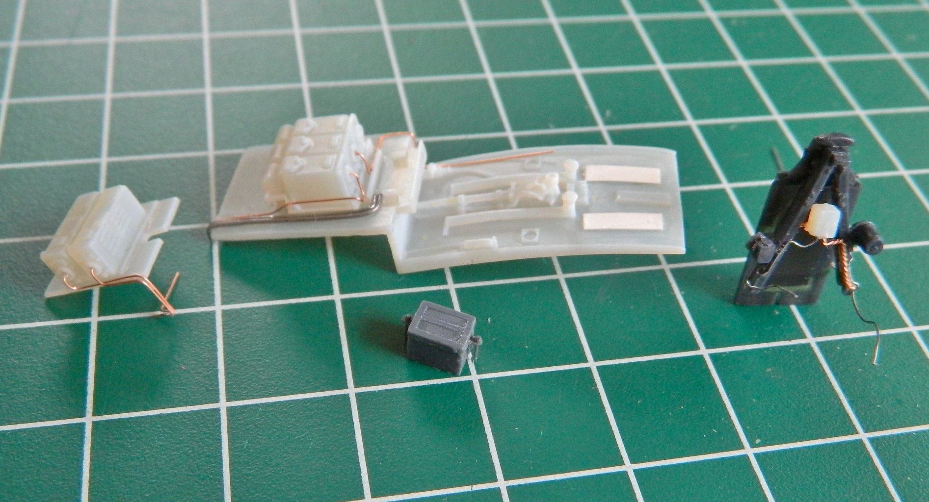

The cylinder on the floor to the right of where the pilot’s seat goes is the emergency hydraulic pump and as such it gets a handle. I drilled it out to accept a copper wire (cleverly straightened out as mentioned above) and then needed to make a knob for the end of it. Often white glue is used to make knobs of this sort, but the actual knob has a flat end which I could not replicate with the white glue. So I dipped the end of the wire in a small puddle of superglue. One of the interesting things about superglue is that when not used to bond things together (hides scarred fingertips behind back), it takes a while to harden and goes through a semi-hard stage. When the blob of superglue became milky, it wasn’t hard yet but had gone past the liquid state. At that point, I pressed the end of the blob against a flat surface and the result was a knob with a flat end just as I wanted:

Sometimes not having four hands (or more) to dry-fit parts is a genuine annoyance. The work-around is to tack things in place with an adhesive that allows easy removal of parts only temporarily in place. If I’m dry-fitting resin, Contact Cement is good for that. But the solvent in Contact Cement will attack and dissolve styrene (don’t ask how I found that out) so when tacking styrene parts together, I use white glue, which is how I attached the two side panels of the cockpit to the fuselage halves:
It didn’t take long for fit problems to show up. You’ll note that the bottom of the side console is straight and flat. But the floor section it’s to meet with isn’t flat and straight. And in the lower right photo, you’ll see that there is a substantial gap at the front (to the left in the photo) where things are supposed to meet:

And not only that but the bottom of the side console also doesn’t match the face of the floor across its surface, as evidenced here (I drew a pencil line, only barely visible in the photo, at the bottom to show what needs to be removed):

And yes, I have the same problem on the other side, too. And in addition to that, there’s NO WAY the carefully constructed pump handle will fit, either:

So much hilarity, gaiety (and invective) ensued as I trimmed, sanded, filed, heated, and bent various resin bits to play well with each other:

And I also had to get creative to get the pump handle to fit around the box on the cockpit side. No, the original handle isn’t bent. Then again, the original handle doesn’t have to fit inside something a half inch wide by three-quarters of an inch long, either:

Another fit problem was created by the molded-on oxygen hose, so that had to be carefully removed:

I found a great replacement, it’s actually a rubber-like material, and will conform to the space it has to occupy:

Looking at reference photos (something I did merely for the novelty of it), I see that the wiring looms/harnesses are quite evident as well as being absent from the resin part. I have a spool of 40 gauge magnet wire that I’m using to create the wiring. And 40 gauge is REALLY small stuff:

By folding the wire, I created two lengths of eight wires each and twisted them into one cable:

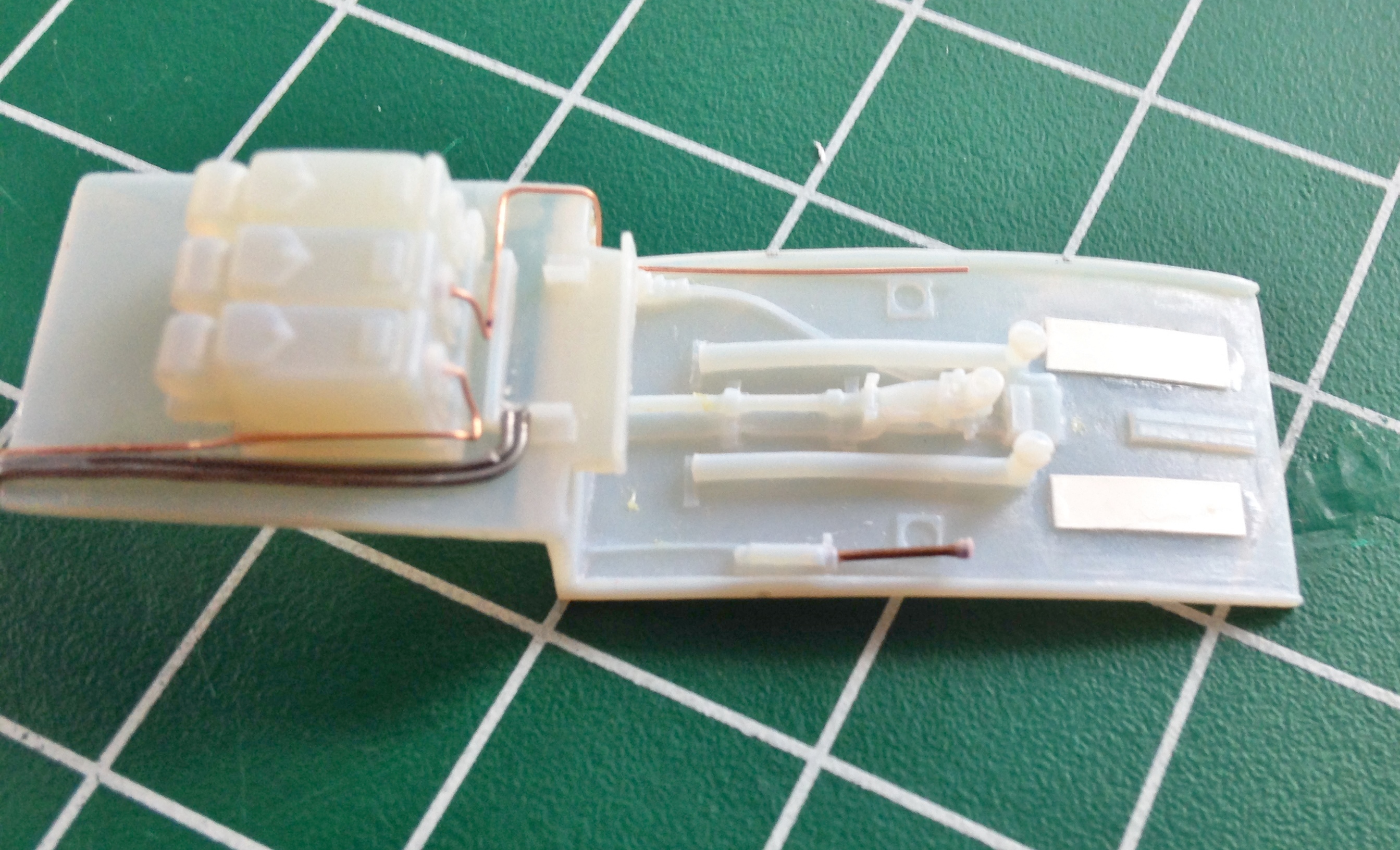
An eight-wire cable is attached to the electrical breaker panel:

The other eight-wire cable was split into two four-wire cables and attached to the radio control panel (on the left) and the microphone panel (on the right). The oxygen hose will be attached later:


P-51 (Accurate Miniatures) Build #2 – Working Cockpit Parts, Adding Details
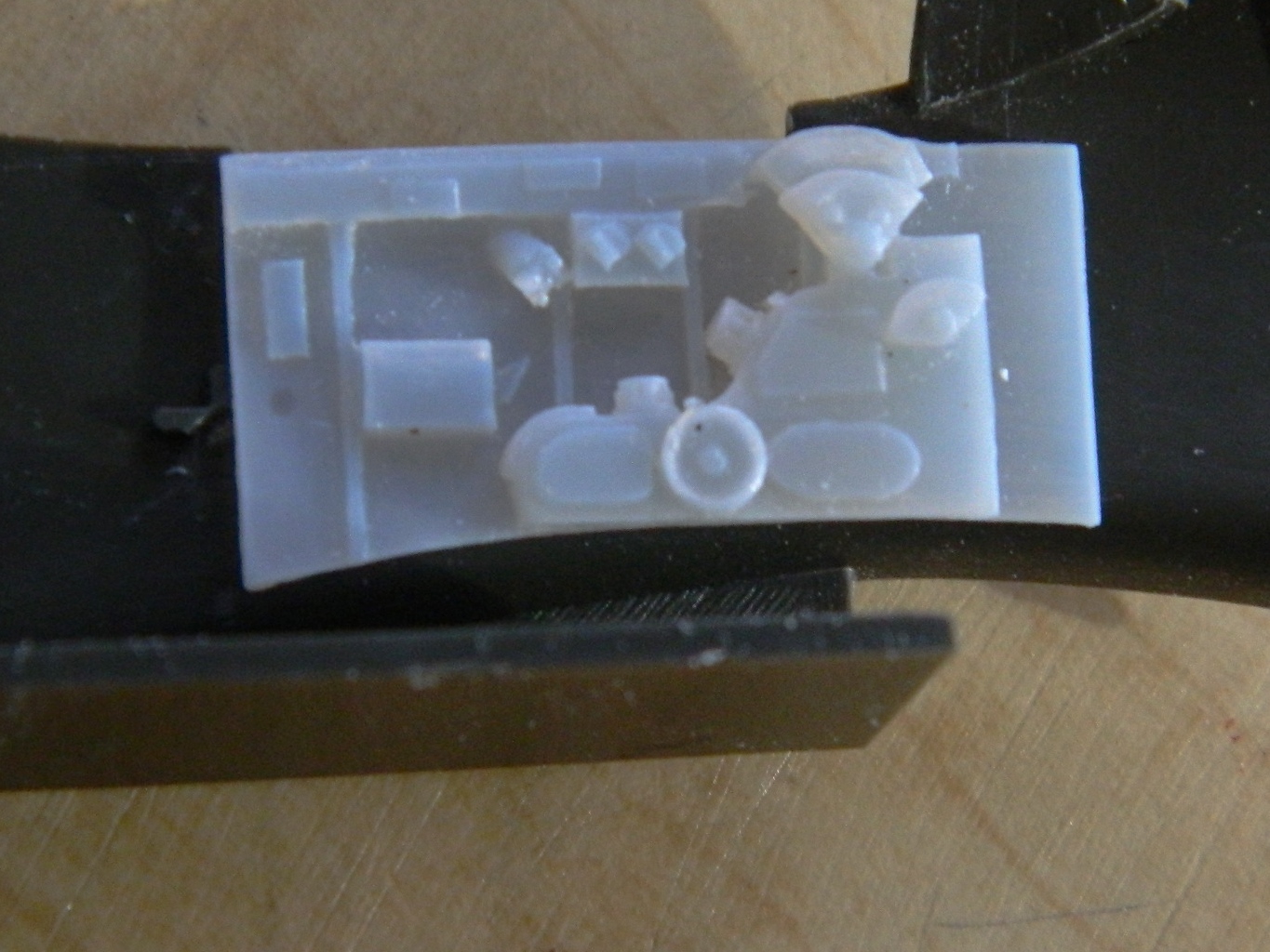
Once I demolded the resin parts, I noticed that there’s a battery that sits on the shelf in front of the radio. It’s a prominent feature that wasn’t supplied with the detail set so I made one (and took a mold of it):

I’ve noticed that my (old) eyes are having difficulty with seeing the surfaces of the resin I’m using so I picked up some black resin dye. I was cautioned that it was highly concentrated so I tried adding a little bit. The effect, though better, wasn’t what I was looking for so I added a lot more. Below you can see the three pours; undyed on the left, lightly dyed in the center, and black on the right:

With the parts produced I want to use, it became time to start checking fit. The rudder pedals are a bit tight to the lower panel of the instrument panel but not so much that I’m willing to jump (crawl and stagger) through the hoops necessary to fix it. But the raised rectangles on the cockpit floor are skid plates for the pilot’s heels and as such should line up with the rudders…which they don’t, so that will need fixing:

In checking the resin seat against photographs of actual seats, the depression at the top of the seat where the shoulder harnesses are isn’t there. That’s an easy fix…just take down the corners:

Since I’m going to be using my rollover brace I carved/sanded/filed the brace molded to the armor plate off as well as removing the raised area on the back (from what I can tell from photos, that’s supposed to be flat). Once the molded-on details were removed, I applied a coat of putty to remove depressions:
Not only should one always check fit, one should check often. Evidently the resin I’m using is very sensitive to heat, even the heat generated by warm hands (of which I have two). The photo on the left below shows that the curve of the “floor” (in quotes because the actual floor of the Allison P-51s is the top of the main fuel tanks) has flattened out. The part I’m holding (with my warm hand) over it is the side panel. The floor is supposed to follow the curve of that panel so I checked one of the side panels of the cockpit to make sure it was supposed to be curved that much…and it is. A quick session under hot water put the curve back that the floor is supposed to have:

I’ve decided to scratch-build an instrument panel instead of using the resin part. Any “detail” on the resin part is rudimentary and I want to kick that detail up. Since I don’t have quite all the gauge faces I’m going to need with the old Waldron set (pity they’re out of business), I ordered another set of gauge faces from Roll Model (I’m told they bought the rights to Waldron so it will be interesting to see what they have available).
P-51 (Accurate Miniatures) Build #1 – Parts Layout, Copying Parts, and Wing Modification
This build will be an early P51 with the Allison engine (though I won’t be adding an engine to the build).
I’ve seen a number of Accurate Miniatures’ P-51 models online and if there’s an exception it’s escaped my notice, but they’re all done with the kit decals that shows a P-51 of the 154th Reconnaissance Squadron out of Tunisia in 1943 with the name, Mah Sweet. As it turns out, there aren’t a lot of decals for the P-51 in 1/48 scale. (Yes, yes…I can hear y’all jumping up and down; of COURSE there are lots of P-51 decals available in that scale, but most of those are for P-51B and P-51D kites. I’m doing a P-51 with no suffix. Different bird.) I did manage to find an out-of-production decal set for early P-51s from AeroMaster (Early Mustangs #48-106). As it turns out it has markings for another P-51 from the same unit, the 154th, but with different numbers and name. That’s the set I’ll use for this build.
This is what I’m starting with:


This is where I want to go with it, which is another P-51 from the 154th (decals from AeroMaster Details set #48-106 “Early Mustangs” and the photo is from P-51 Mustang in Action from Squadron/Signals Publications, Aircraft #45, page 12):

And these parts are what I plan on adding to the build:

Back in the early ’90s, P-51D kits were made by seemingly everyone in many different scales; there were a few P-51B kits, but nobody was making any Allison-engine P-51s. So of course I wanted to build one. I found a resin conversion kit that replaced the fuselage halves of Monogram’s P-51B and started work. But just before I had to move and lost shop space, I noticed that the sides of the nose had a different cross-section between the Merlin engine and Allison engine Mustangs. Construction stopped while I figured out a way around that problem, and then moving really stopped construction. However, some of what I had done I would be able to use with this build.
The Verlinden set offered me the resin armor plate and A-brace but I don’t think it goes quite far down enough. I pulled my scratch-built piece out and compared them:
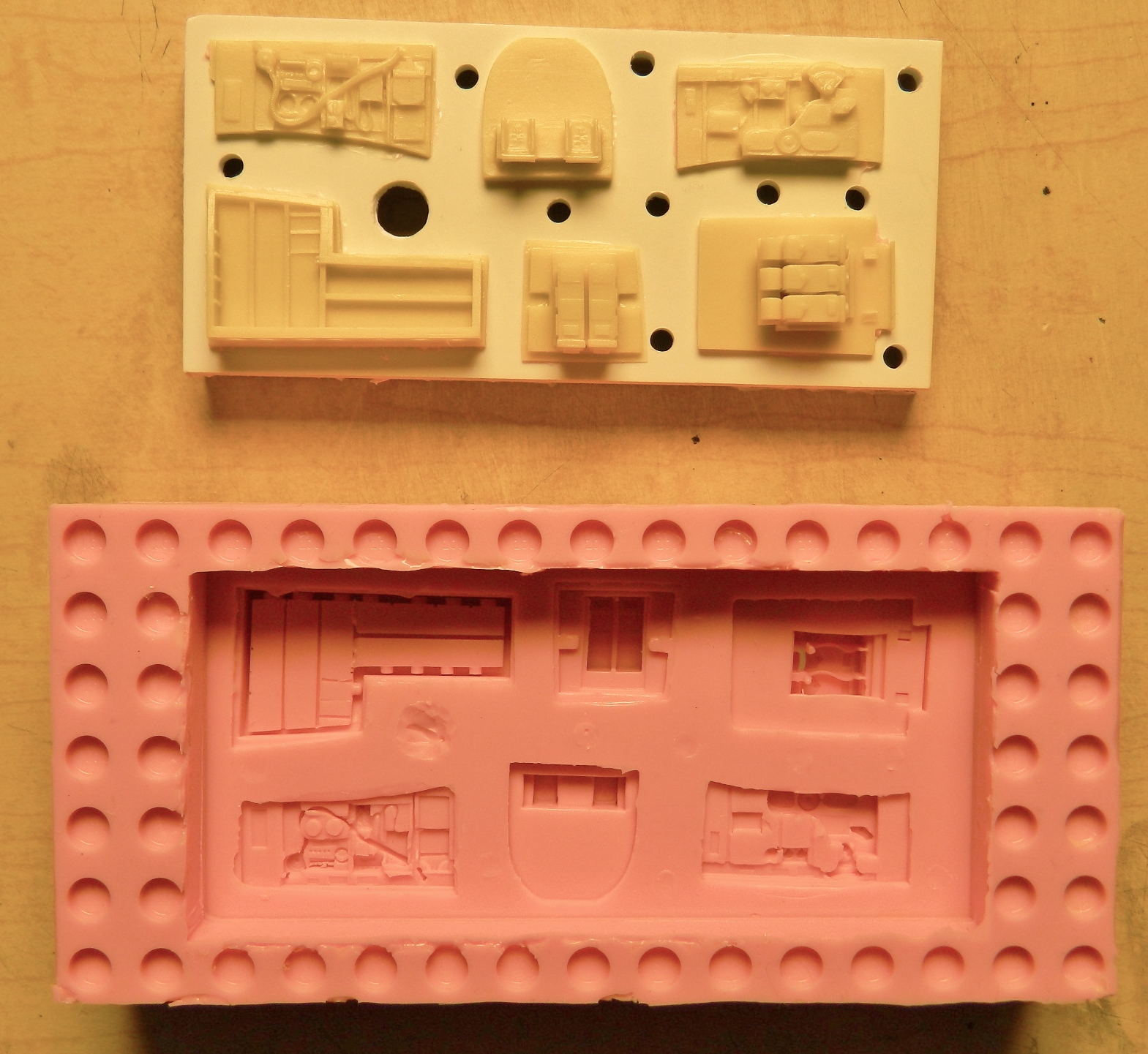
I decided to use the A-brace and its assorted bits. But since I’m going to be doing a few Allison Mustangs, I didn’t want to have to scratch-build that assembly again which meant making a mold of it to cast those parts in resin. It was heartening to note that when I glue something together, I glue something together. It was more heartening to not break anything while separating the parts for the molding process:

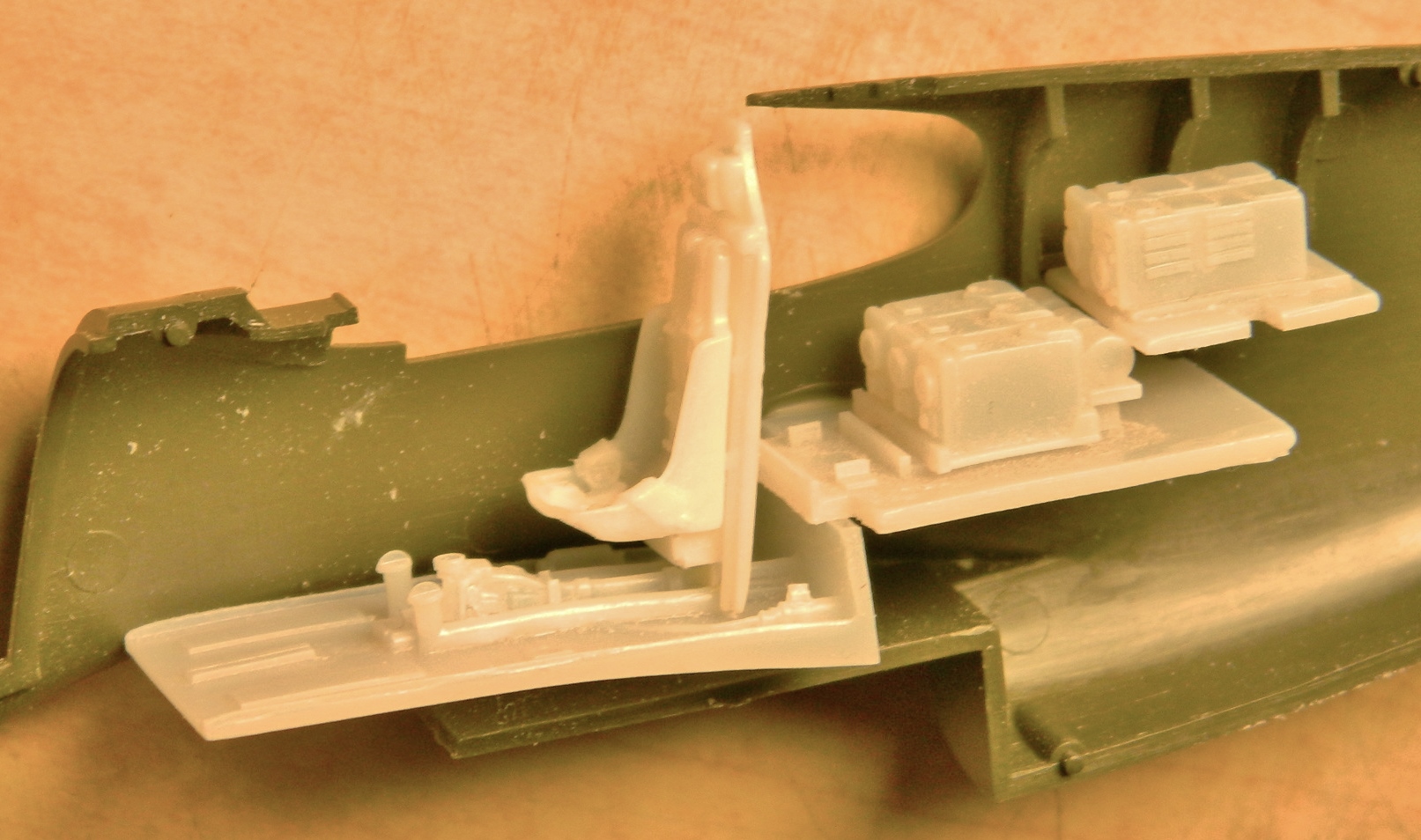
Once separated, the parts needed to be gated so that I could pour them. I also added plastic to the back of the instrument panel so that it would pour easier:


I also took molds of the other parts in the set:

I think it’s safe to say that pretty much all kits have something wrong with them. In this situation, I’m encountering the commercial balancing act between engineering and producing an accurate kit and yet still keep the final cost of the kit reasonable, and the Accurate Miniatures kit, though quite a leap forward at the time (the early ’90s), was no exception.
The first thing I noticed is that the landing gear wells are going to need to be reconstructed (and yes, once they have been, I’ll take molds of them and use resin castings in the builds). The rear of the landing gear wells is molded pretty much the way everyone else at the time molded them in this scale. And pretty much like everyone else producing these kits, they’re wrong. The rear of the wells doesn’t follow the openings in the wing surface the way the kit parts do. If you look into the landing gear well of a P-51 (which I have), you’ll see (like I did) that the rear of the well isn’t V-shaped as it’s been molded but is open all the way back to the main spar. And the ribs are not only not that thick (they’re aluminum stampings), they have lips around their edges for rigidity. The kit has none of those features so most of the molded-in wells are going to be cut away and replaced:

The top of the wells (or bottom, as you look at the above-left photo) are actually the underside of the upper wing surface of the actual Mustang. That means I have to blend the lip below into obscurity:
To do that, I’m going to need to follow the inner curves of the wing so that the parts fit. But to get that inner curve, I’m going to have to assemble a wing and then section it so that I can trace the inner shape. I only have one P-51 kit, but I have a few P-51A kits, and though the armament of the two variants was different, the wing is the same. So one of my P-51A kits has become the donor kit:
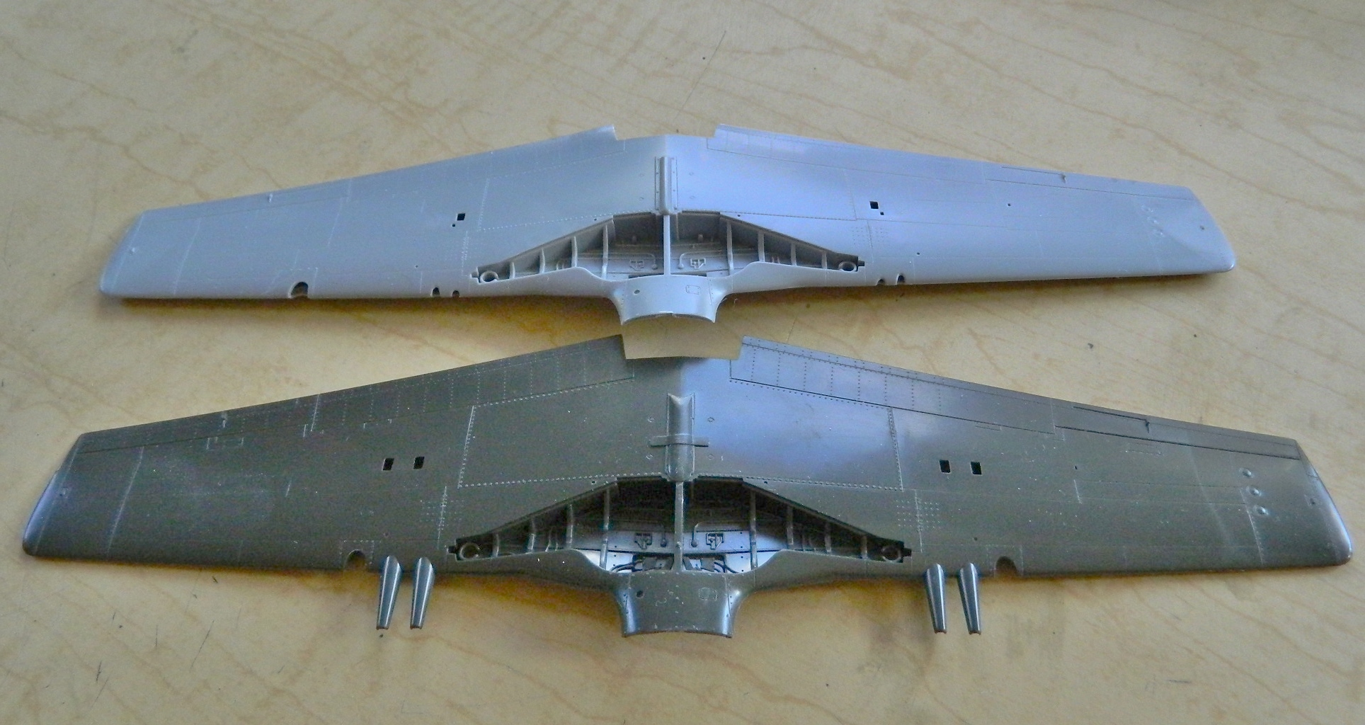
The lower-right photo has arrows pointing to the rib I’m going to want the shape of:

The wing was cut just short of the rib so that I could get in there with a pencil. The inner protrusion is part of the section where the landing gear leg attaches and I’m going to want to keep that for structural strength when the landing gear is attached, so the rib has to be built around that protrusion. Once I had the section I wanted cut free of the rest of the wing, it got taped to a sheet of .040″ (1.016mm) styrene and the inner shape traced:
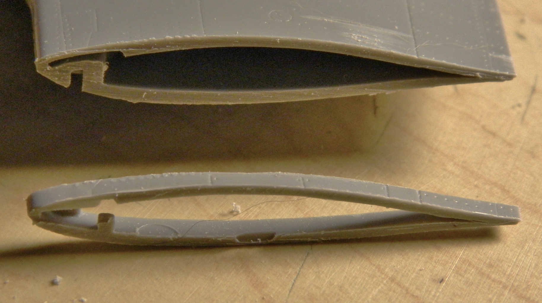

Once I had the rough shape outlined, I cut, carved, cursed, filed, cursed some more until I finally got an adequate fit. This piece will form the outer end of the well:

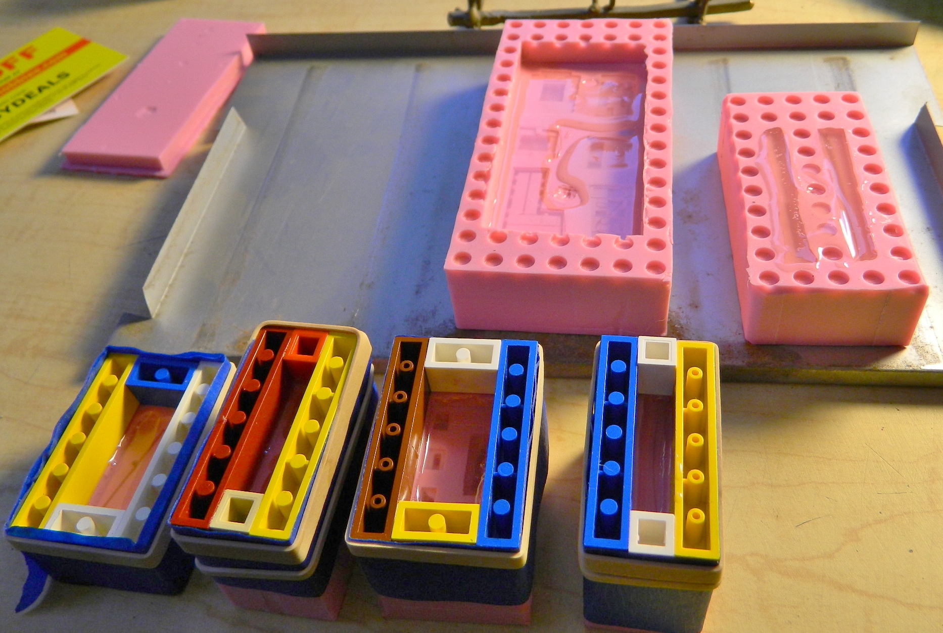
While I was working on that, I was also pouring resin into my new molds (the Lego blocks were taped to the edges of the molds to see if I could get a better reservoir for the resin and though I did, the “benefit” of that reservoir wasn’t worth the hassle of it all):
With the parts out of the molds, trimmed, sanded, filed, and cursed at (really, I’ll take any excuse to exercise my ability with colorful invective), the dry-fitting began by tacking things together with white glue and contact cement: