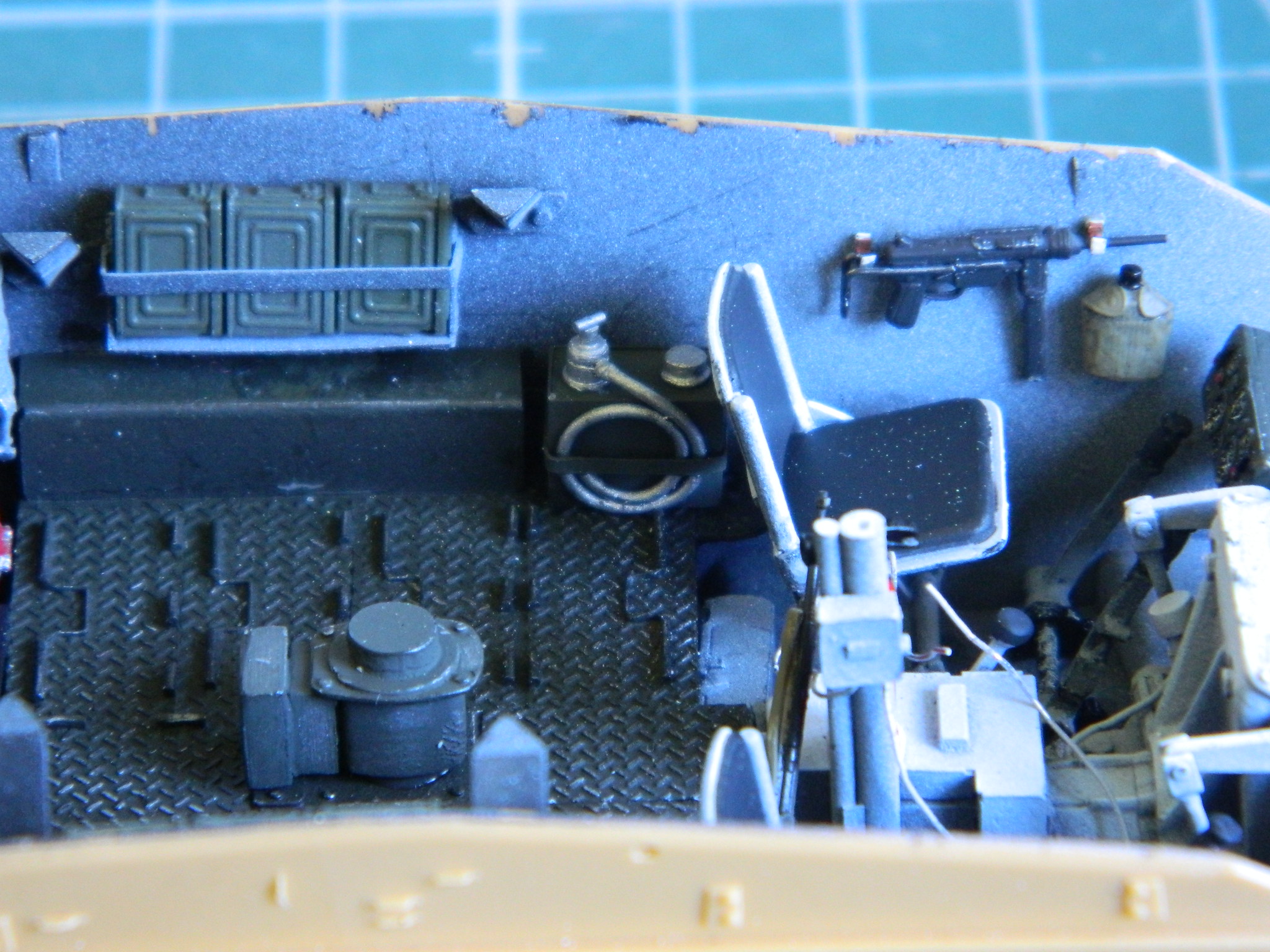
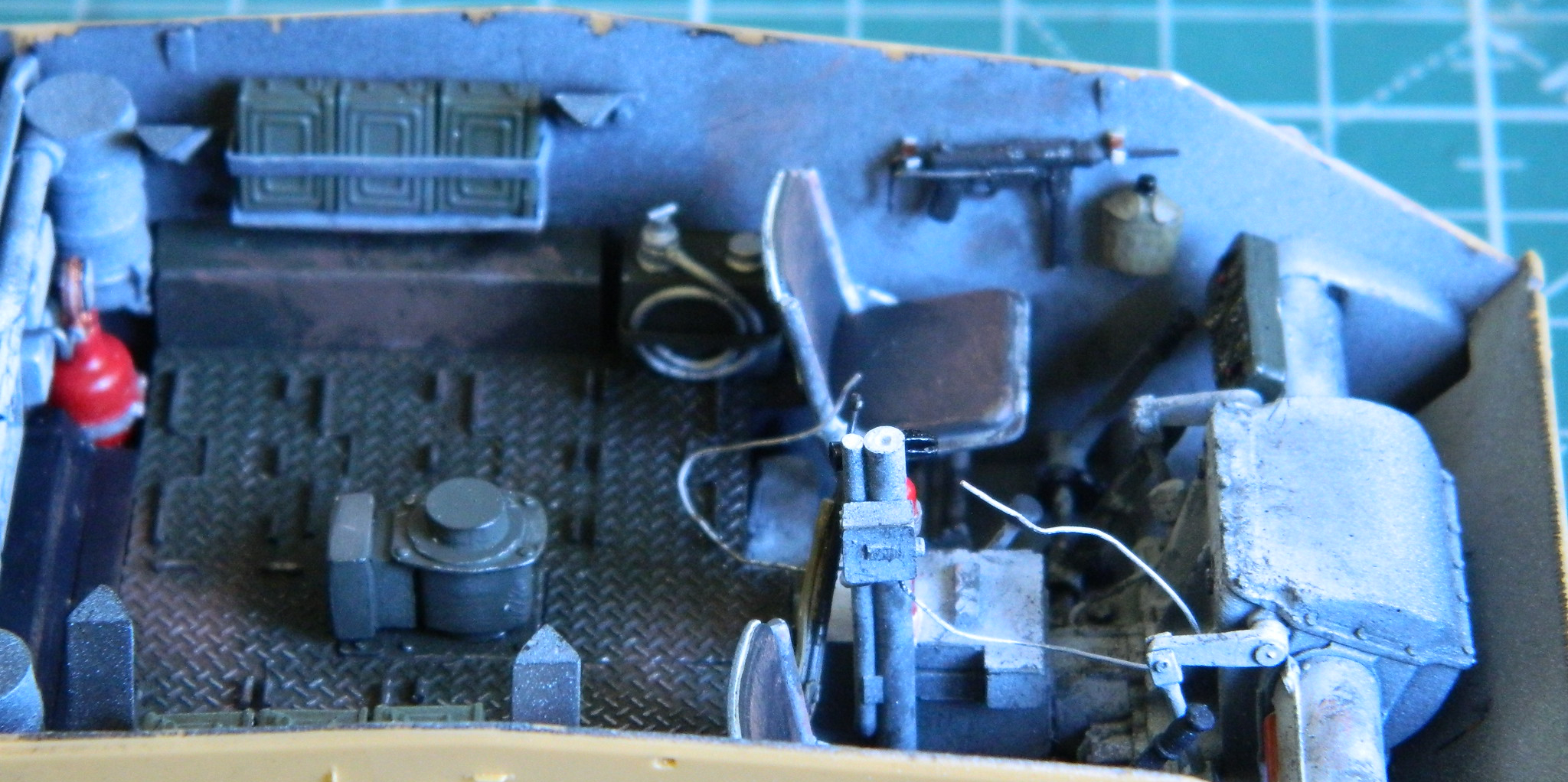
Now that many (but certainly not all) of the small details have been painted, it’s time to put them where they’re going to stay. The .30 caliber(7.62mm) ammo stowage racks were mounted to the sides and the M-3 “grease gun” and canteen were mounted to the side of the driver’s position:
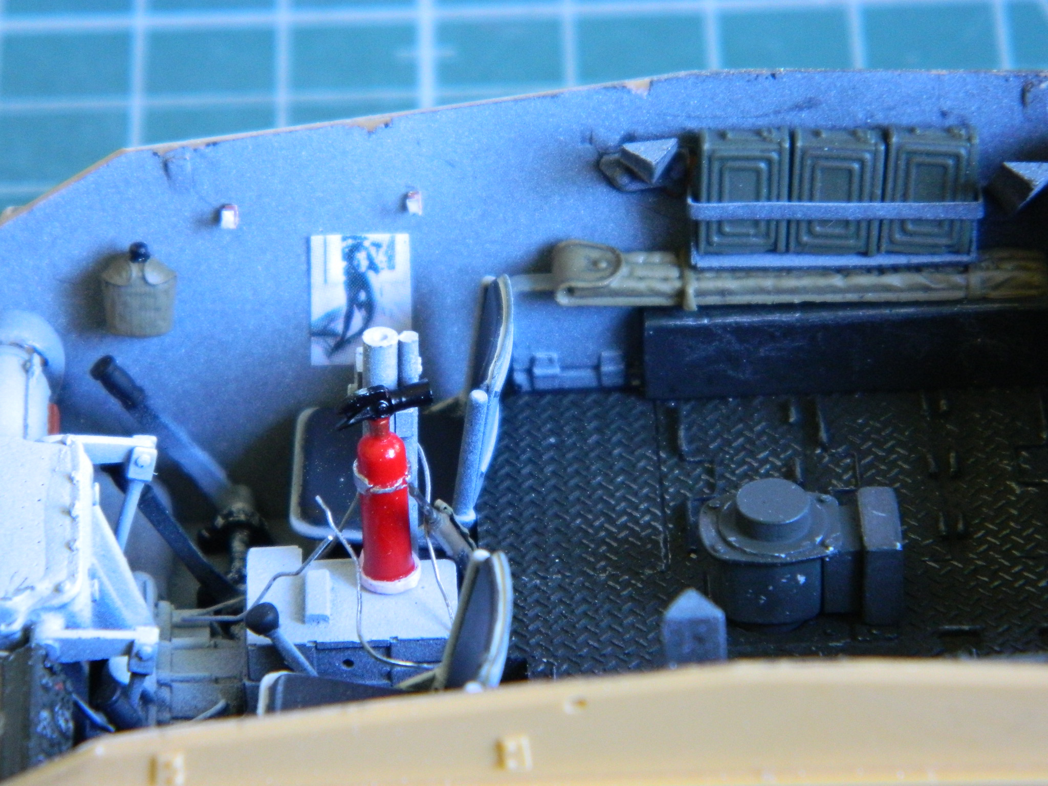
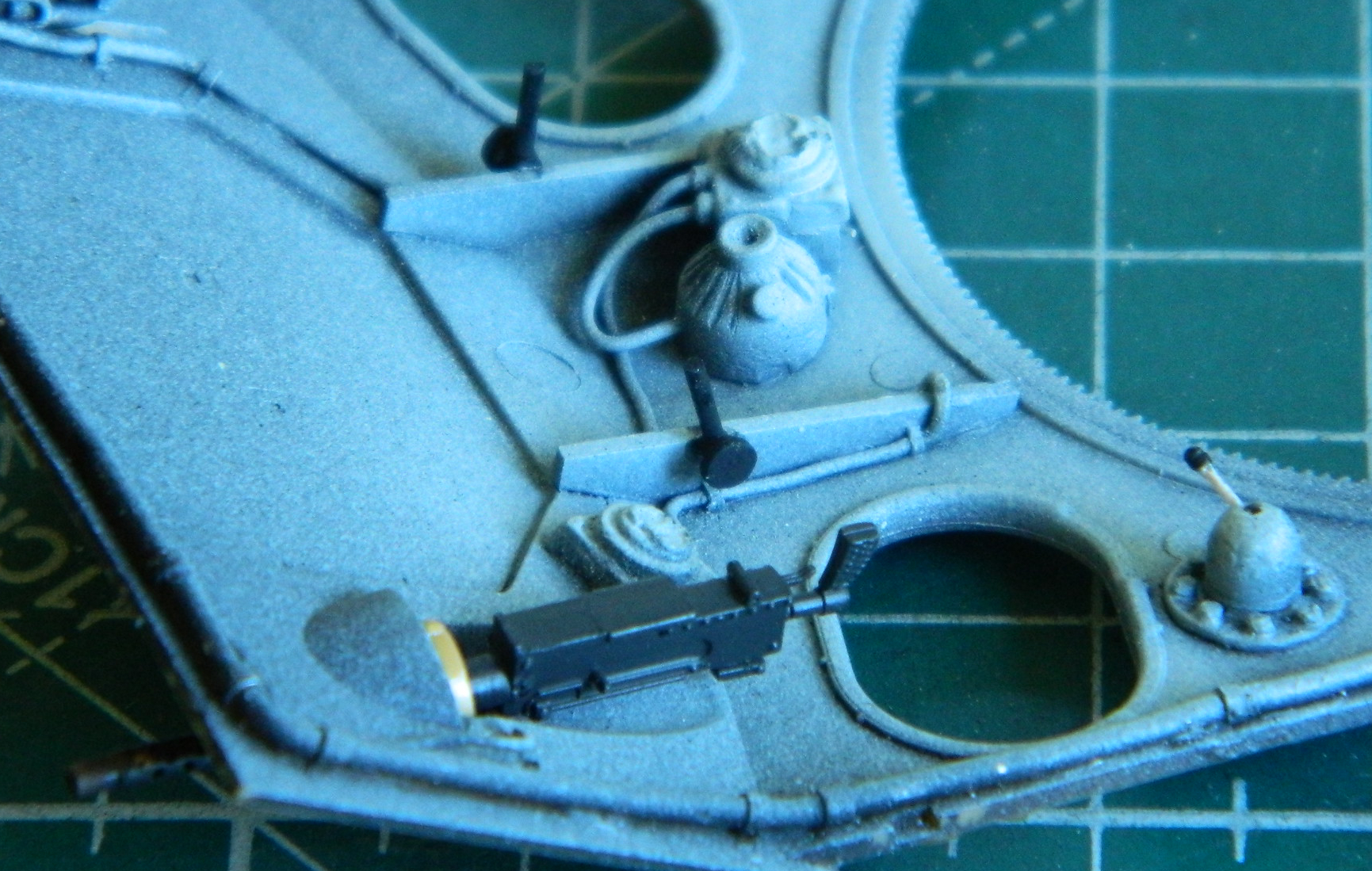
The pin-up (Rita Hayworth) and canteen were mounted next to the co-driver’s position and behind it in addition to the .30 (7.62mm) ammo stowage, the signal flag bag was slid in (barely) underneath it:
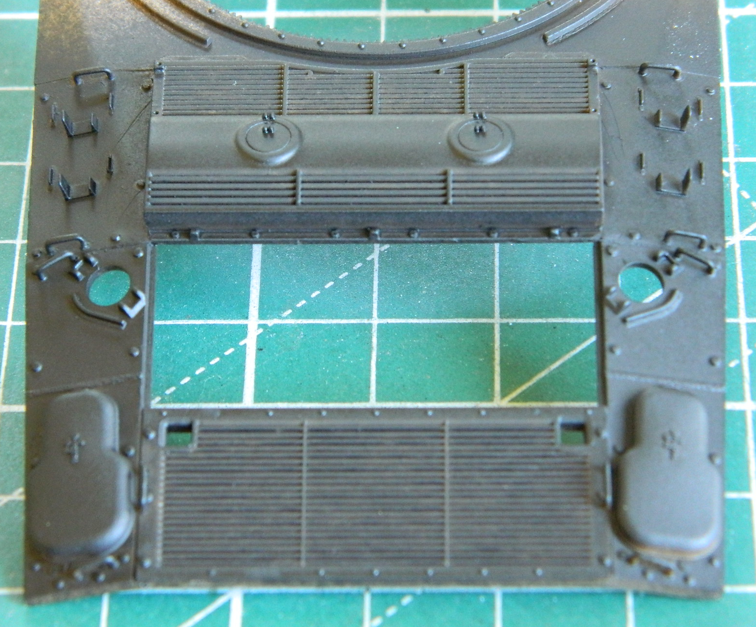
I turned my attention to the rear of the tank and discovered that the engine cover was just a bit too wide, so that will get taken care of later:

One of the prominent features in the engine compartment is the throttle linkage. The first step to making that part was to find out how long the cross-shaft that connected two carburetors to one lead foot had to be and a compass with two points did that well:
There is a linkage arm that’s attached to the cross shaft and to replicate that I used a #75 (.025″) (.635mm) bit and center drilled the end of .035″ (.89mm) rod to make the attachment base of the linkage arm:
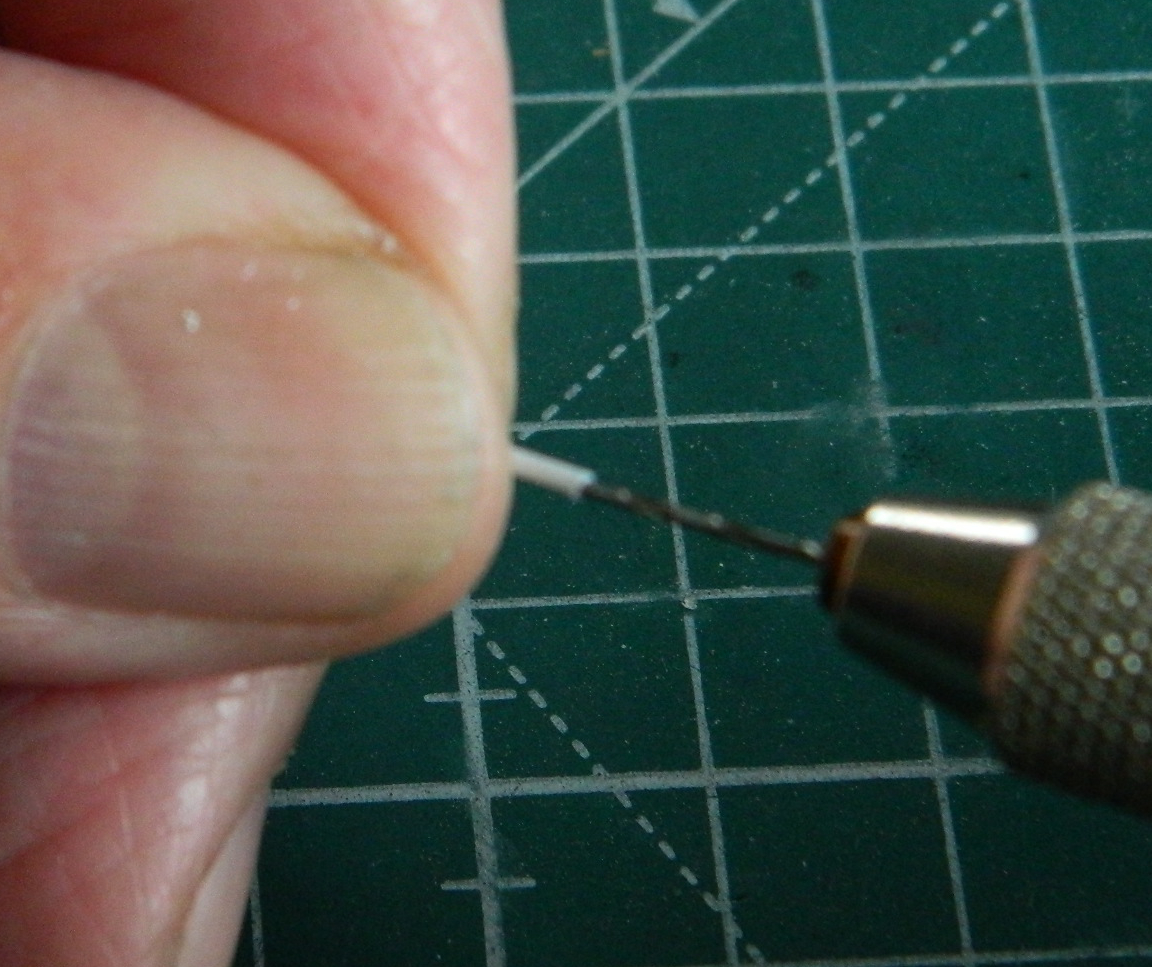
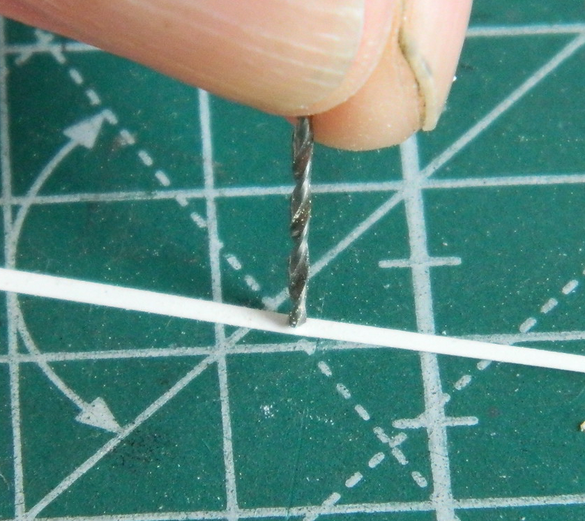
To make the linkage arm, I used a piece of .005″ (.127mm) scrap and used a #65 (.035″) (.89mm) bit to make a curve where the arm mounts to the cross shaft:
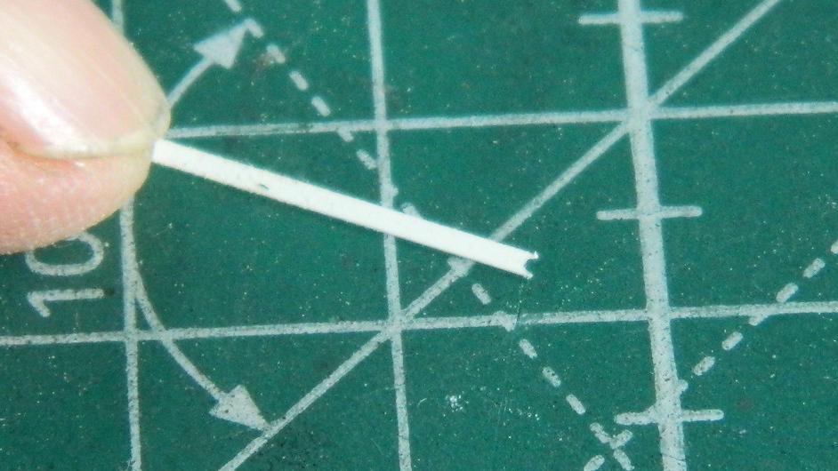
The styrene was cut across the hole leaving a semicircular cutout to glue to the mounting base of the linkage arm:
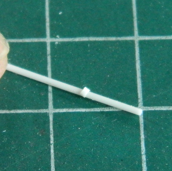
A small section was cut off the drilled out rod and slid over the rod that will serve as the cross shaft:
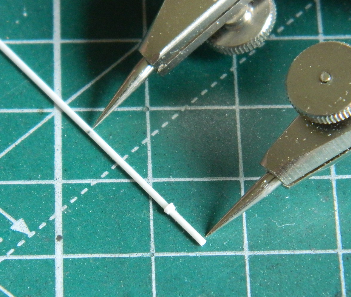
Then the length of the cross shaft was transferred to the rod and the cut was made on the mark:
The arm’s base was centered and clamped in locking tweezers on a base, then the trimmed linkage arm was aligned in another locking tweezer on a base and both parts glued to the cross shaft:

While the glue was curing, I started assembling the main gun since work inside the turret is rapidly approaching. A part of me really appreciated the very fine molding of very small parts that inhabit this kit’s box. A part of me wonders why the aerial intercourse a sub-assembly that could make do with three or four component parts needs TEN OR TWELVE component parts! Really…too much of a good thing is more annoying than merely “too much.” An example of this is the main gun (though it is far from the only example in this kit). This thing is comprised of twenty-three separate pieces (it would have been twenty-four if I’d used the gimmicky recoil spring that allows the barrel to move backwards in the receiver). I neglected to take a photo of all the parts laid out; here it is with construction already started:
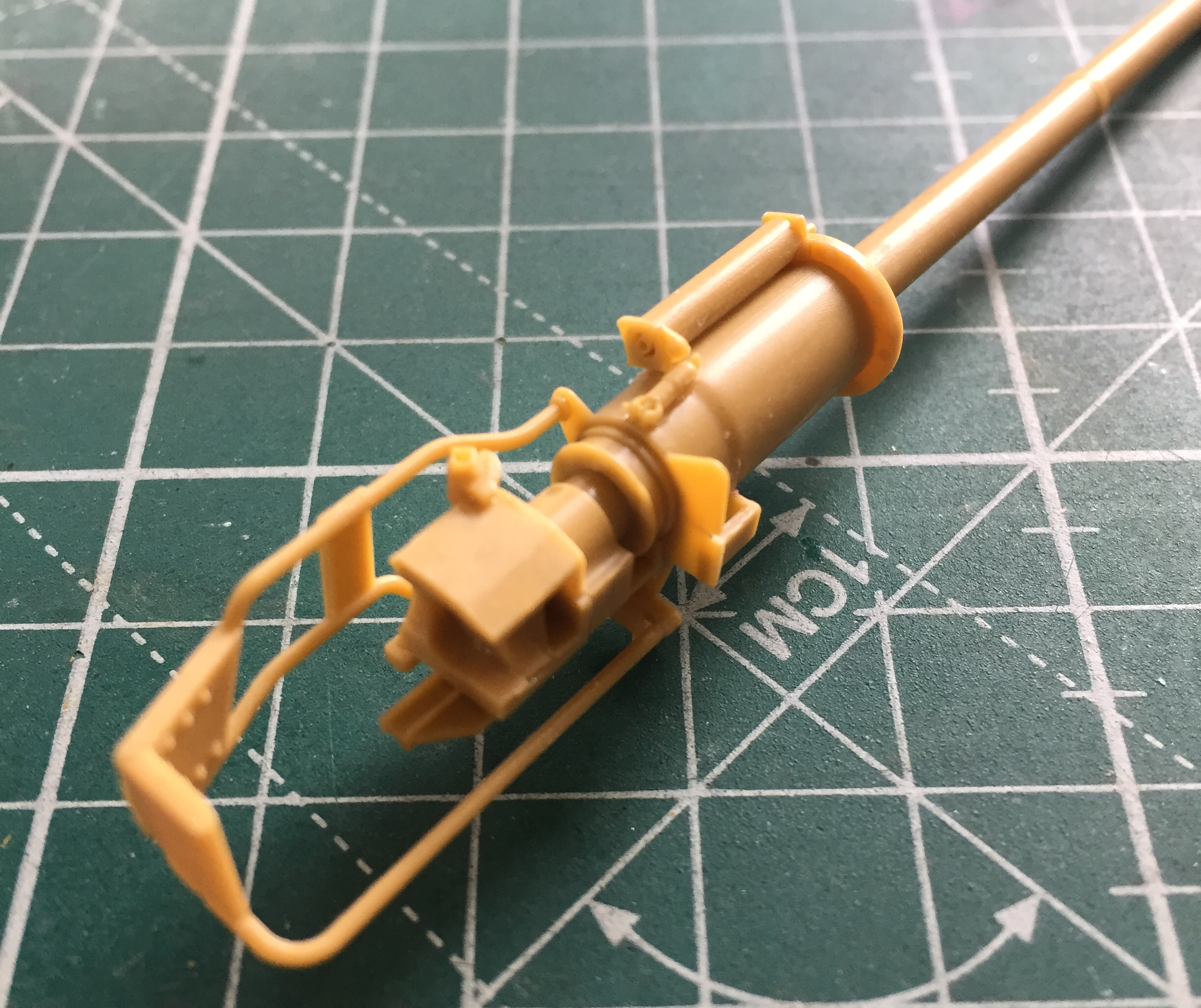

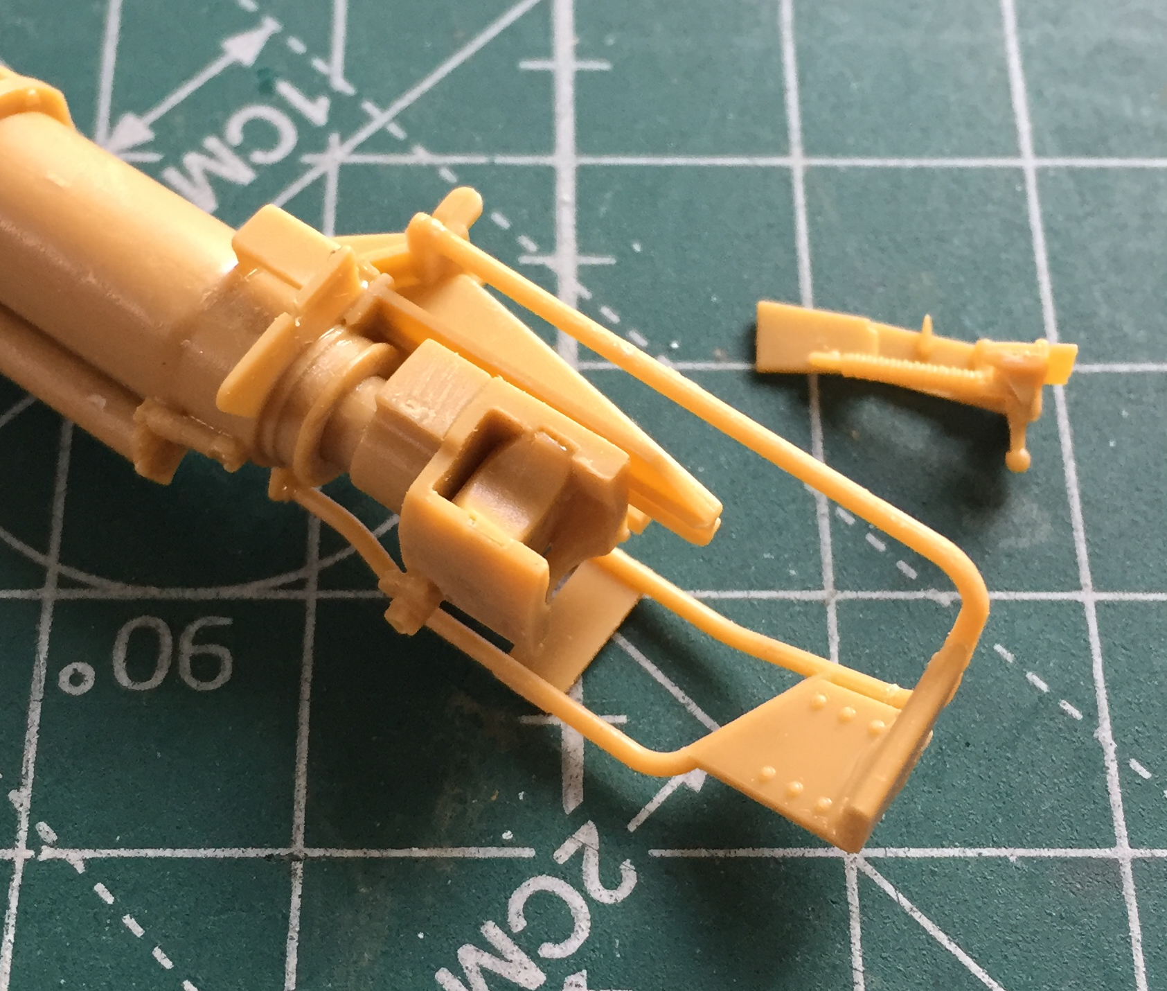
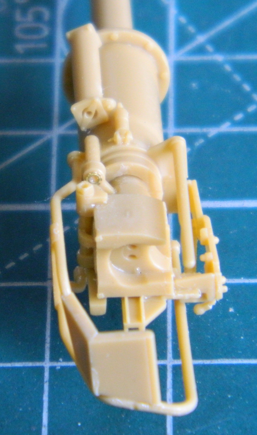
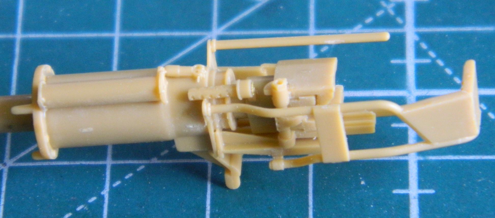
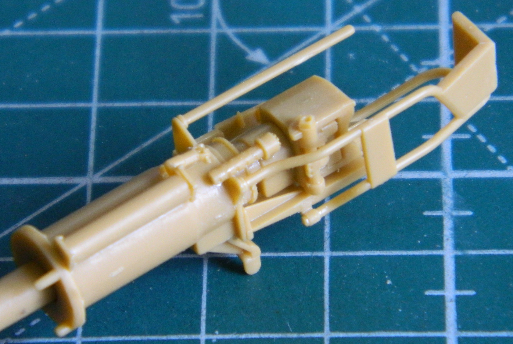
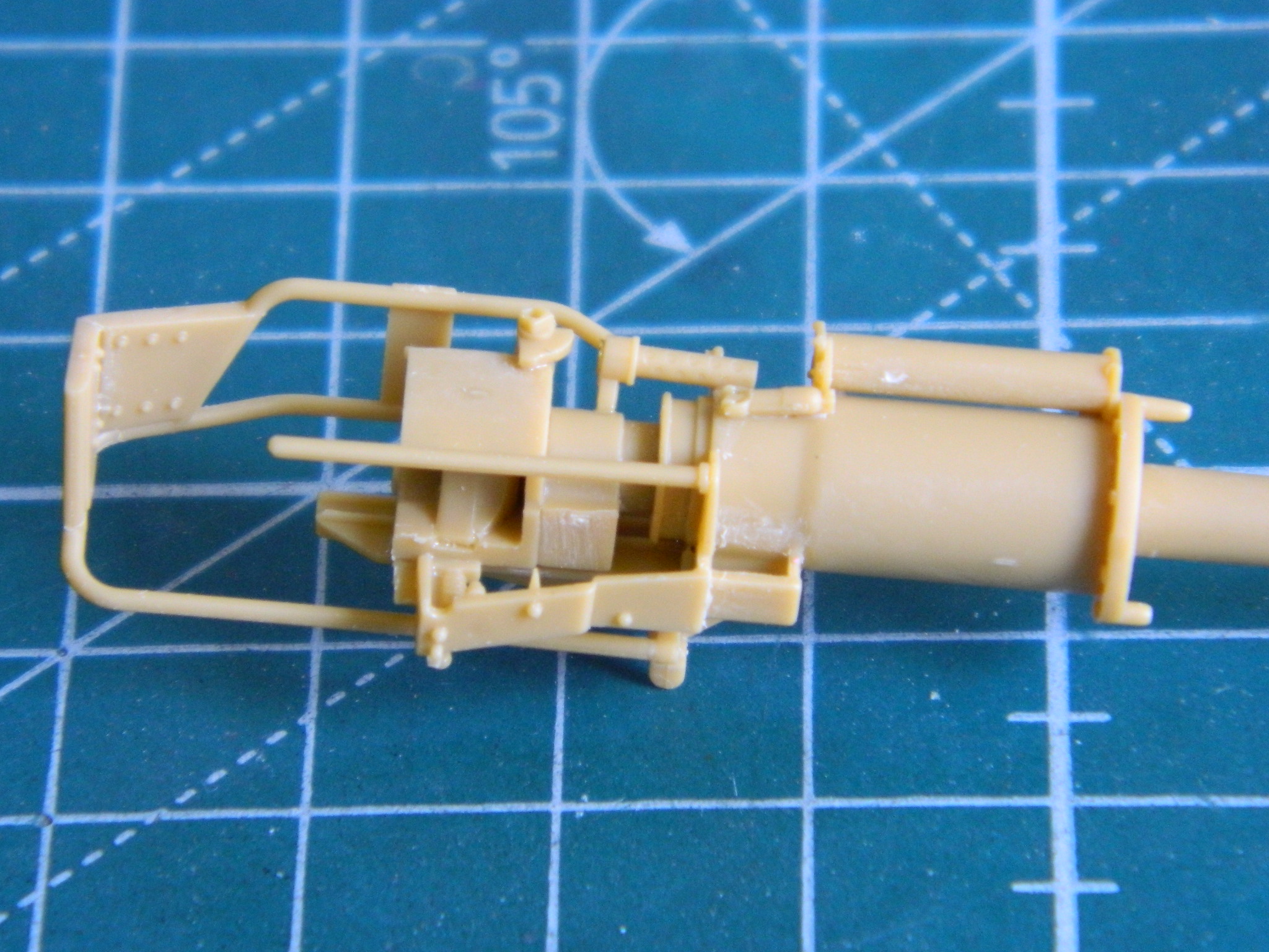


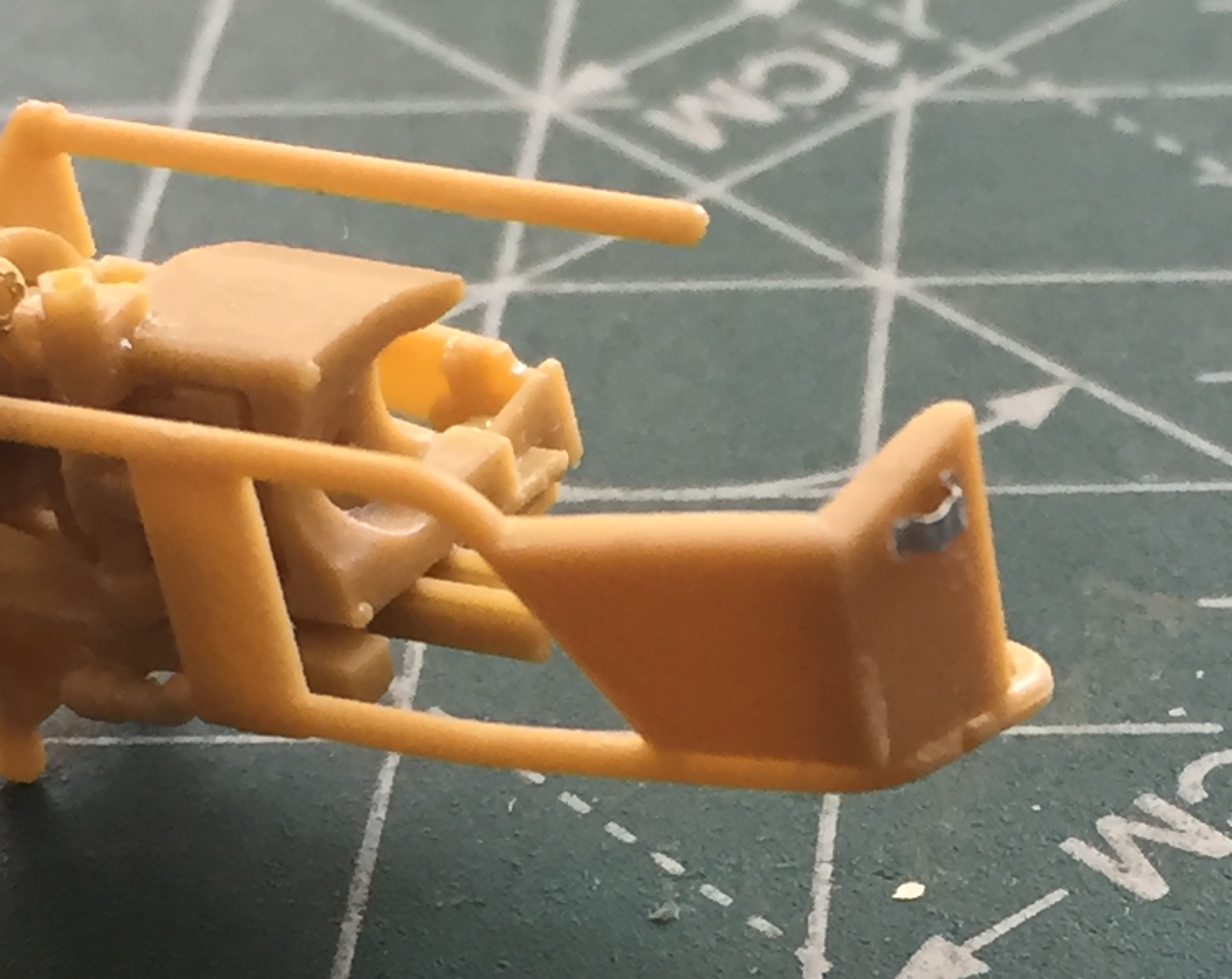
If having twenty-three parts to this gun wasn’t enough pleasure (spits), there are no location marks or pins. None. Sherlock Holmes, Hercuile Peroit, Travis McGee, and my mother would have been impressed by my investigative efforts to get (what I hope is) a reasonably accurate representation of the T13E1/M5 gun (the two rings cast around the barrel show this, correctly, to be the 75mm tube from the ground attack variant of the B-25 it was taken from). I was impressed that Bronco also molded in rifling in the muzzle (sorry but this was the best photo I could take of that given the light and the autofocus’ unwillingness to focus where I wanted it to focus):

Masking and painting this thing will probably drive me to drink (something to look forward to…while I can still see).
Oh. And as if there weren’t enough parts, I discovered that Bronco, in all the parts they made for this thing, actually forgot two! They forgot the breech opening lever and the bracket it stows in when not in use. So I had to make them.
The socket was made from a piece of sprue chucked into my lathe, turned to the appropriate diameter, and the edges of the nut cut (CAREFULLY) in. A scrap piece of .015″ (.381mm) styrene provided the handle:

I used a piece of aluminum to make the stowage bracket, and although pleased with my efforts, I realized later that where I have the bracket is too high. It should be centered on the rear of the recoil guard and later I moved it down to a less incorrect location:

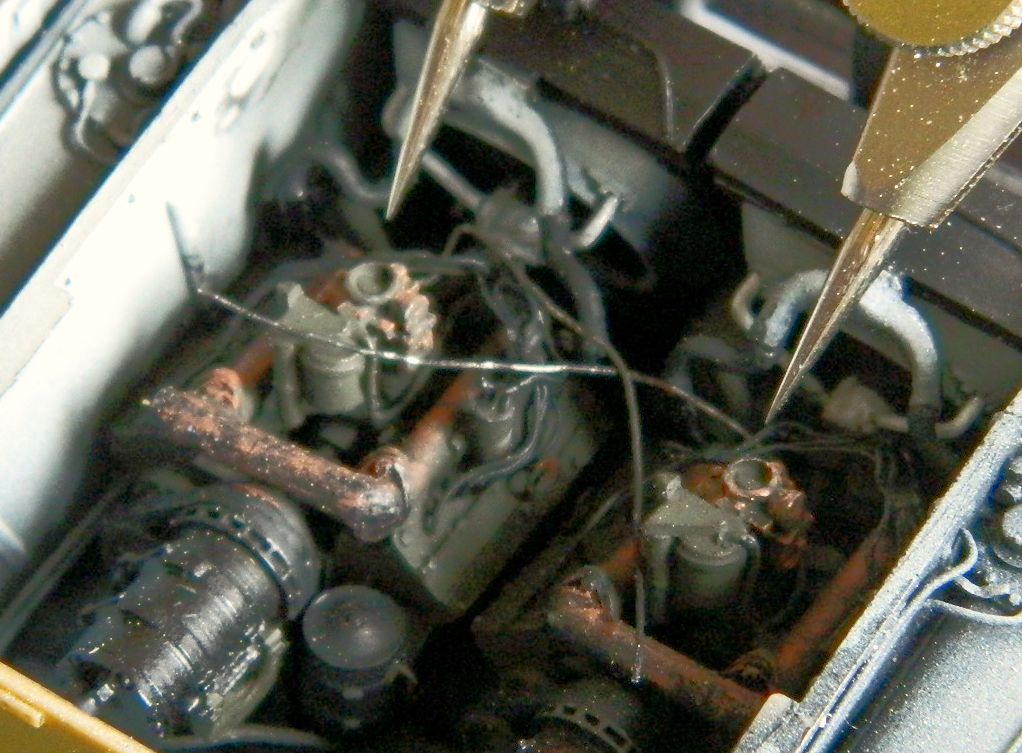
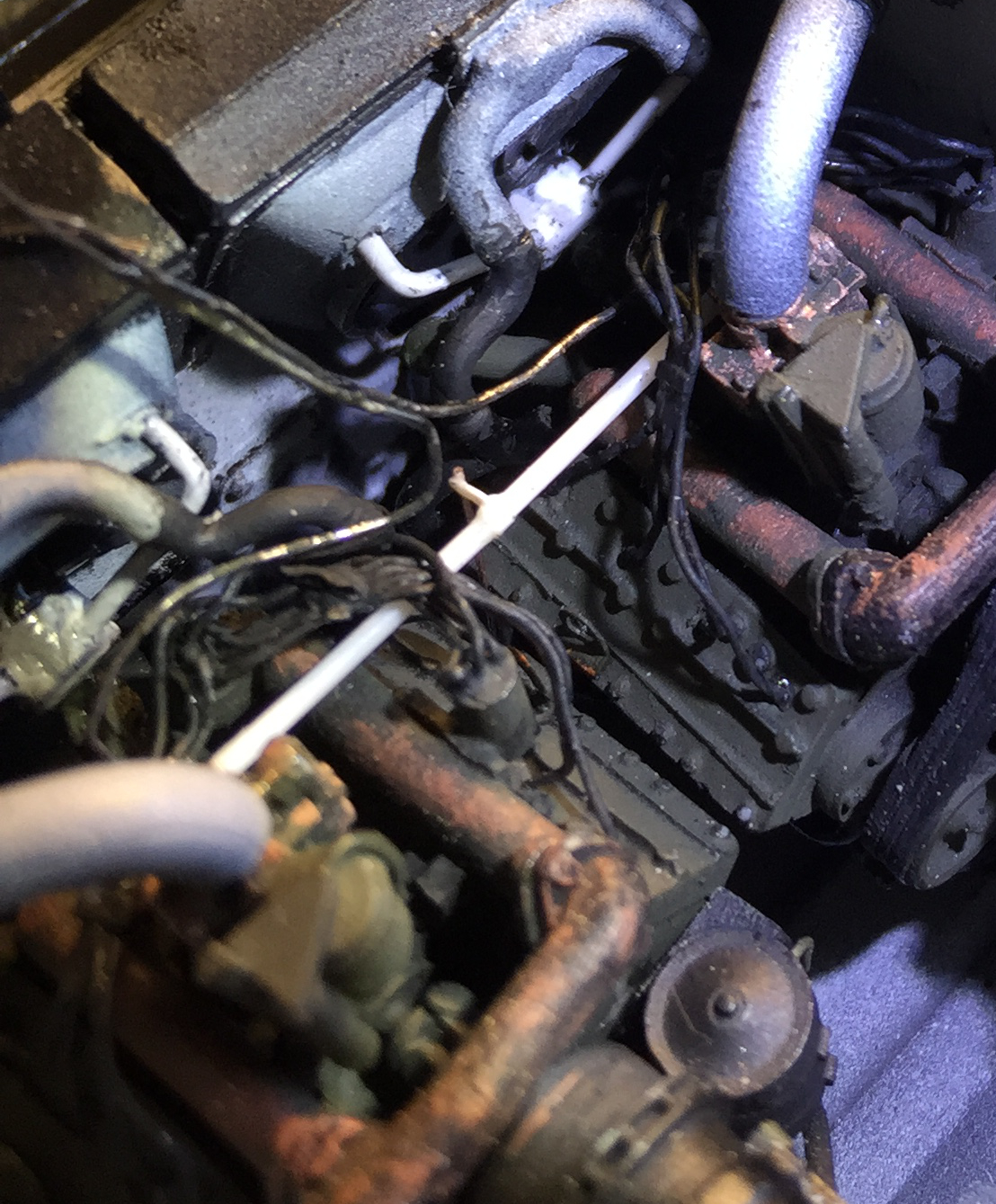
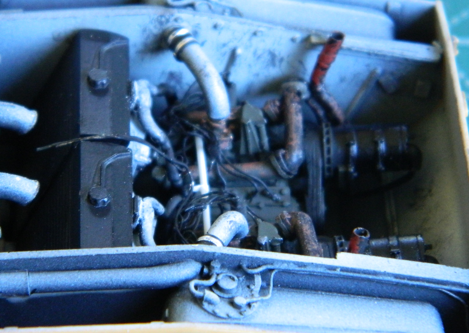
After dealing with the main gun for a couple of days, the glued parts of the throttle linkage was thoroughly dried and cured, so that got installed. It had aspects of trying to give a snake an enema and several of the delicate solder “wires” were dislodged, but obviously I don’t know when to quit so the installation was accomplished:

The next serious test of patience and commitment was installing the mufflers and exhaust tips. I’m very glad I decided not to mount these parts before engine installations because had I gone ahead and mounted them, the right engine would never have fit…not even remotely. A little foresight helped a bit when I drilled out the parts that had to be mated and added pins. But to get the right (or starboard) muffler to sit where it needed to (more on that shortly), I had to grind away substantial portions of the inner bottom of the muffler and the outer side of the oil filter. The good news is even knowing that moderate surgery was necessary to get the starboard (or…well, never mind…you get it by now) muffler into position isn’t evident. It’s a tight space and the black pre-shading hides the butcher…er…surgery. But it turns out there was one more tiny little thing.
Getting the exhaust pipe to exit the upper hull where it has to is that “little thing.” If the exhaust pipe lines up along the vertical axis, it doesn’t even come close to the opening provided for it. (Part of me wonders if that’s because the engines are probably misaligned…another part of me doesn’t give an intercourse.) I rotated the muffler/pipe around the pin glued into the cross-pipe until the tip of the exhaust pipe was under the little square opening. Now (as it is in other things), I just needed a longer pipe.
It turns out that .062″ (1.57mm) solder is the exact diameter I needed to lengthen the pipe! (Would that other lengthening were that easy, or even possible.) I drilled out the ends of the solder and resin pipes, added a wire pin, and then glued the solder to the resin:


A little paint, a little glue, and that problem was solved! (One cannot count on luck, but it’s sure nice when it shows up.)
With the “pipes” correctly aligned and installed, they needed to be cut to the appropriate length and the ends drilled out so that they look like pipes (alignment where the solder meets the resin is slightly off, but once painted with the top hull plate in position it’s unnoticeable):


I GLADLY turned my attention elsewhere! The next major step is to get the upper hull glued down to the lower hull. There were still a couple of items I needed to attend to before that could happen, the primary one being the bow machine gun. The kit parts are fairly decent and given the location of the bow machine gun, it’s not going to be easy to see the receiver. But the barrel will certainly be easy to see, so I worked those next.
My go-to for coloring brass machine gun barrels has become Birchwood Casey’s Brass Black Metal Finish. The Polish company, Master, makes exquisitely turned and drilled, two-piece (separate barrel and cooling jacket), brass barrels in their Ground Master series for 1/35 scale machine guns. They’re so finely constructed that paint plugs things up. When I was building the M-3 Stuart, I ran across BC’s blackening compound and discovered that it does a BRILLIANT job of coloring the brass without adding perceptible mass to the barrels or plugging the holes in the cooling jacket.
Use of these barrels requires that the molded on barrels be cut off, a socket be drilled for the pin on the end of the barrel, and the barrel glues on. So far, so good. However, the bow machine gun is slightly different from the co-axially mounted machine gun. There is a ball around the base of the barrel and a sleeve that connects the ball to the gun (allowing the machine gun to traverse and elevate in its mount). So, yeah…I had to drill that out, too:

Whew. Nerve wracking.
The barrels were masked (I used a tube of paper) and the receivers painted with five parts Tamiya X-18 Semi-Gloss Black and four parts Tamiya XF-20 Medium Gray. I like this combination SO much better than any “gun metal” paint I’ve yet encountered. It has just enough sheen to look metallic and avoid the toy-like appearance “gun metal” paints strike my eye as:


Other than replacing the barrels because they’re visually evident, I didn’t do much detailing on the .30 cals (7.62mm) because they’re not easily seen. (Of course I did some because, well, I HAVE TO!) So far in my experience, I like how Bronco does their .30s (7.62mm). It’s nice not having to add those tiny, sodding, triggers myself…
One last look at the innards before the upper hull goes on. Dirt and wear were added, things were chipped and worn. And in the first photo below you can see the crew’s microphones “hung” from the upper hull supports. There are NO words that can convey the ABSOLUTE FRUSTRATING TEDIUM involved in getting the solder “wires” connected to the ends of them:


I sprayed the rear upper hull Tamiya TS-6 Flat Black (rattle-can) to pre-shade all the louvers and grills:
And the major step of marrying the upper hull to the lower has happened:


Now to work on the turret…

And here I thought quilters were crazy.
LikeLike
They are! Clearly, they have no monopoly on crazy. *I*, however, am not crazy. I’m colorful.
LikeLike