Since the first time I saw a photo of one, I thought the Bugatti Type 35 was about the most beautiful race car of the period. The ensuing decades have not changed my opinion. It’s gorgeous. I forget which particular Internet rabbit-hole I had been diving into when I ran across Monogram’s Bugatti Type 35B. It took a little looking to find an acceptably-priced kit (I’m not a collector and don’t give an intercourse if the seal has been violated or not and I’m not going to pay collector prices) but I did and now I have this little gem:

The box contained these sprues:

Right after the vinyl tires (gah), the first thing I noticed was all the chrome. (Okay, it’s actually aluminum, which worked to my favor shortly.) That’s got to go. I filled a tub with household chlorine bleach and immersed the chrome sprues for about ten minutes. That stripped the sprues to the bare plastic with zero harm to the styrene:

These parts are supposed to be aluminum. I have paint for that, though I will be using BareMetal Foil’s “Ultra-Bright Chrome” for the outside of the radiator housing, which seems to have been polished aluminum. That done, I set the de-chromed sprues to the side and started with the third thing that caught my eye. The hood (or bonnet, if you prefer). I want to pose this with the right side hood open and I can’t do that without cutting the hood apart, something I would be totally comfortable doing. Then I realized that even if I did cut the hood apart, I’d still have parts that were not only far too thick, none of the louvers, of which there are plenty, would show up on the inside.
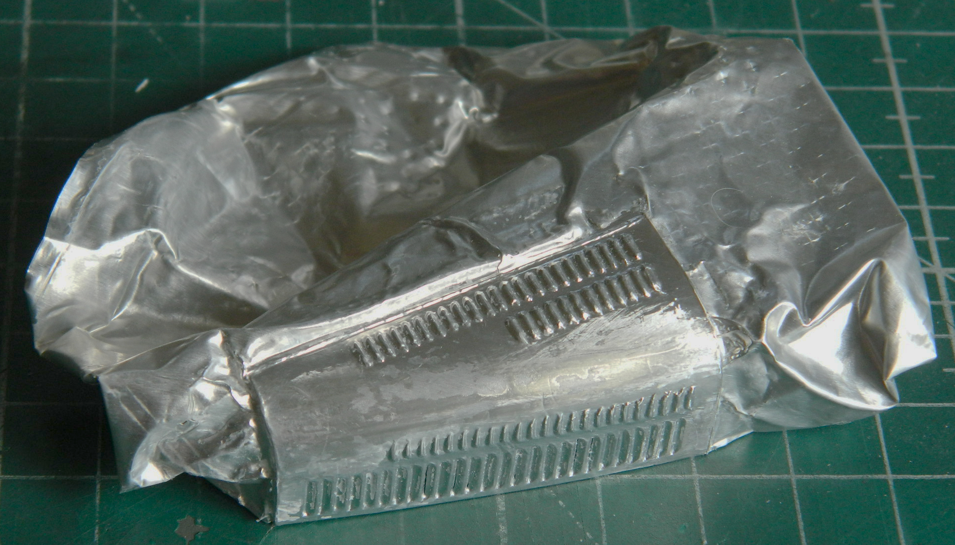
I used to smoke (what…you’re pefect?!). I mention that for two reasons. The first is to remind you that I am far from perfect (or even rational, too often). The second is because the cans of tobacco I smoked (I rolled my own…a better grade of tobacco and much fresher) came sealed with a disk of relatively thick aluminum foil (.004″ or .0039mm). I used another piece of this foil successfully as quilted padding for the inside of my Gemini build (::spits::) and it immediately came to mind. So while watching the idiot box (TV), I folded the foil tightly around the bottom edge of the hood, used scotch tape to hold it in place, and started embossing it:

I used round toothpicks sharpened to a relatively dull chisel tip and just stayed at it until I got here:

I used a new single-edge razor blade to trim the aluminum from the plastic part (the hair is provided by Her Sacred Majesty, Mistress of All Time and Space, and Unrepentant Spider Bane…the cat):

Truth be told, this was just a proof-of-concept task. Since it was successful, later I went back and did a tighter job with it. And, in case you’re new to this site, it’s at this point I mention my relative lack-of-sanity. For about five minutes I actually considered cutting out all the openings to all the louvers. I got over it. Paint will do. Reluctantly. With the concept proven, I only had to do it one more time. However, that was the last piece of that aluminum foil I had and it wasn’t large enough to use for the other side. I do, though, have more of the type, it’s just a little bit thinner:
Being thinner, the aluminum settled down to the surface details tighter. I considered redoing the first side again with this foil, then I realized that the first side, being a bit thicker, would probably stand up to being displayed unsupported better. How much better? Dunno. I can always do another one with the thinner foil later. And speaking of later, later on I considered what color I was going to paint this beauty. Being built as race cars, the inside of the bodywork wasn’t painted. It was bare aluminum. Well, that’s already taken care of!
Turning my attention to the instrument panel, I realized that at best it was wrong. Other parts of this kit suggest to me that the engineers copied a car that had been modified from the original 1927 car and that several things were going to need attention:
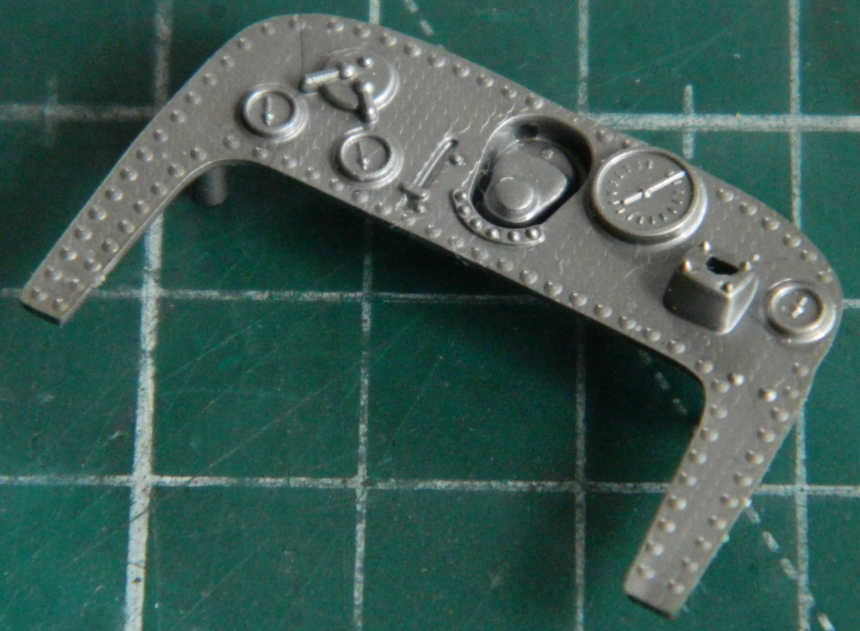
The switch panel above the two small gauges on the left simply wasn’t there in 1927. A clock was (when you see him, ask Ettore why…I haven’t a clue). The area in the center of the instrument panel was actually the back of the distributor and protruded further into the cockpit than the kit has molded. I decided to fix that first by cutting away the depression from the back, trimming down the lip around the resulting hole, and gluing it back in with more protrusion. And of course I didn’t take a photo of it. (Probably before the caffeine hit the remnants of my brain.)
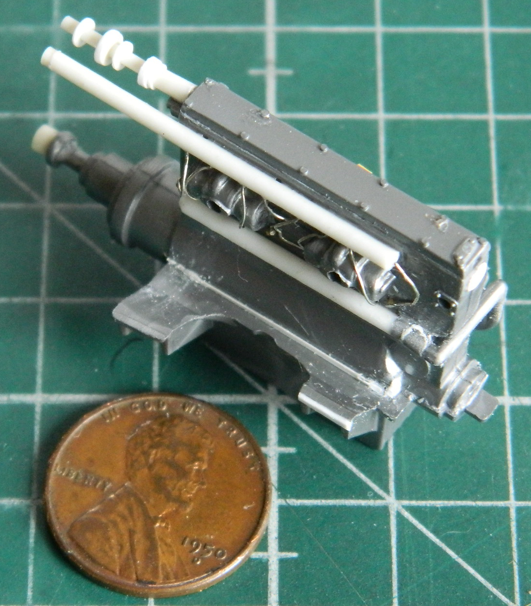
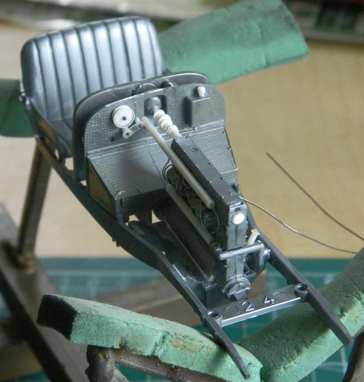
The engine is moderately accurate but could use some detailing. From the left side of the photo below, I added a stub of styrene to the end of the driveshaft so it would meet the transmission. The long styrene tube replicates the tube that carried the ignition wires, which I replicated with .010 (.254mm) solder and the plugs are small stubs of stretched sprue (they’re there, they just can’t be seen easily). The forward engine mounts weren’t quite long enough so both sides were shimmed with .020″ (.508mm) scrap. The styrene tube above it and attached to the back of the engine is the shaft that runs from back of the camshaft to the the distributor and also is where the belt-drive for the tachometer is. The styrene tube lower on the side of the engine is a water pipe. Since there were gaps where it meets the forward support, I filled them with .010″ (.245mm) scraps and 3-M Acrylic Putty. There were gaps all around the bottom of the engine block where they meet the oil pan which were filled with varied thicknesses of scrap styrene and more acrylic putty. On the left side of the engine I added the tall filler tube and cap for the oil and the smaller, towards the front, filler tube and cap for coolant (the part that looks like a turbocharger housing is actually the water pump) using styrene rod for the tubes, and punched out discs and stretched sprue as caps for both fillers:

The rear of the distributor drive shaft should socket into the distributor on the firewall, so I drilled that out so it would. The right side (of the photo) of the firewall has an oil reservoir and the filler tube and cap were molded to the firewall. For the body of the reservoir, that was okay. I redid the filler tube and cap using scrap styrene rod before using .015″ (.381mm) solder as the oil feed line and standard aluminum foil as the hold-downs for the oil line. The molded-on line on the right side below the oil tank will be removed later (“later” often means with me that I just overlooked it or, more likely, forgot). The left side of the firewall has the pulley and tensioner for the tachometer drive belt. As molded they were unacceptable, and since they will be foremost in the vision of the viewer, they needed to be fixed. I used a tap/die to punch out the discs (.040″ or 1.016mm) for the body of the pulley and the flanges were .010″ (.254mm) and stuck on a Grandt Line nut/bolt of what looked like the correct size. A note about the clear disc. When I have to align a disc to something and using opaque styrene would make that more difficult, I use clear instead. It makes alignment so much easier and once painted nobody can see that it’s clear. I used clear styrene of the same thickness on the part below the pulley, which is the tensioner arm, pivot, and belt bogey along with more Grandt Line nuts/bolts:

When I had the distributor cut away from the instrument panel, I drilled out the eight holes for the spark plug wires using .015″ (.381mm) solder for the wires and added them. Once they were glued in place (superglue), I glued the distributor back in place. On the left bottom side of the cockpit (as viewed from the cockpit), there is an arm for an oil-replenishment pump that the kit didn’t allow for. I carefully scribed a slot for the arm to fit into, then used scrap styrene to make the grips for it (it’s below the instrument panel and to the left). There is also an arm that allows the driver to retard the spark for easier starts, then advance it once the engine is running. I used .005″ (.127mm) copper shim stock to replicate it. I’ll add the oil pump arm once the instrument panel is ready for paint and installation (who knows…maybe I won’t break it off a couple of dozen times) (yeah, right):
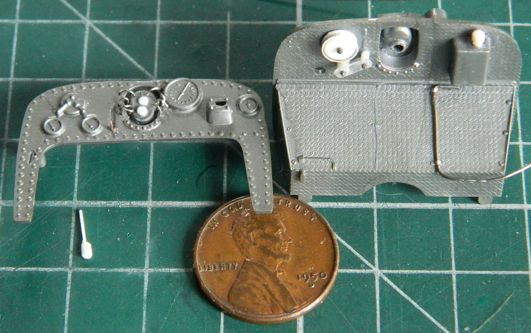
I glued the instrument panel to the firewall and then dry-fit them, the engine, and seat to the frame to see how fit was looking. Not too badly:

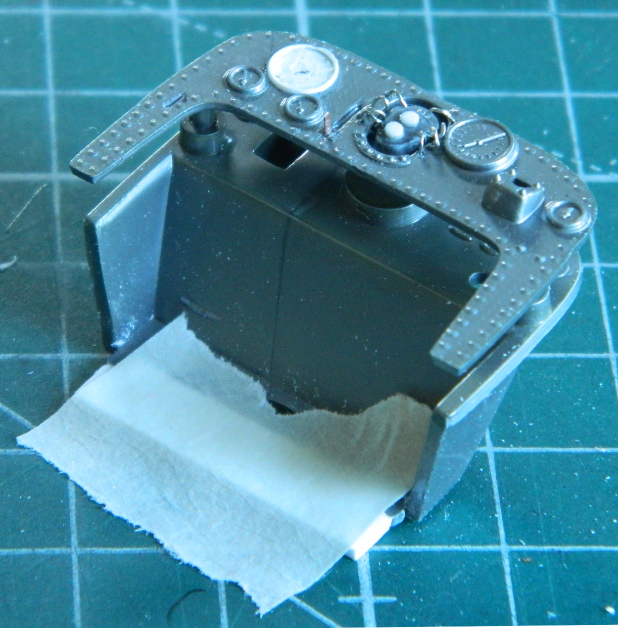
Before I went any further, I wanted to remove the erroneous switches on the left side of the instrument panel and replace it with the “clock”. I used an .010″ (.254mm) ring I’d punched out for a different build without using, and a disc of .005″ (.127mm) as the clock’s face. Once under paint, I’ll use a VERY sharp pencil to draw in the lines and probably very thin sprue as the clock’s hands (the assembly was taped to the cutting mat so that I could stop chasing it all over the place). I will probably treat the other instruments with the paint/pencil regime:
I started detailing the supercharger next. At the top of the supercharger in the photo immediately below is the manifold for the pressure-relief tube. It was molded solid so I drilled that out. At the bottom of the supercharger is the intake and carburetor, the intake of which also had to be drilled out. Then I started adding more Grandt Line nuts/bolts where these manifolds were attached as well as lightly scribing the separations between the manifolds as well as adding .015″ (.381mm) solder for the fuel line:


There will be more work on this part, including the throttle linkage (that’s going to be like giving a gnat a Price Albert, assuming gnats had johnsons).
At the top front of the engine head is an elbow fitting where the oil line from the oil reservoir mounts, replicated with small styrene rod scraps:

On the actual car, the transmission is right there next to people’s legs. I’ve read that it got HOT. The reason I stated earlier that I suspect the engineers had looked at a post-period modified car was because it appears as if a “thermal blanket” was molded in place around where the transmission would go:

The whole section in front of the seat has to come off. That leaves me with nothing much to put there so I have to scratch-build the transmission. I was off to a roaring great start before I realized I was copying the wrong variant! Well, there’s another addition to my scrap styrene stock… I made a block of Aves AepoxySculpt and started whittling away at it:
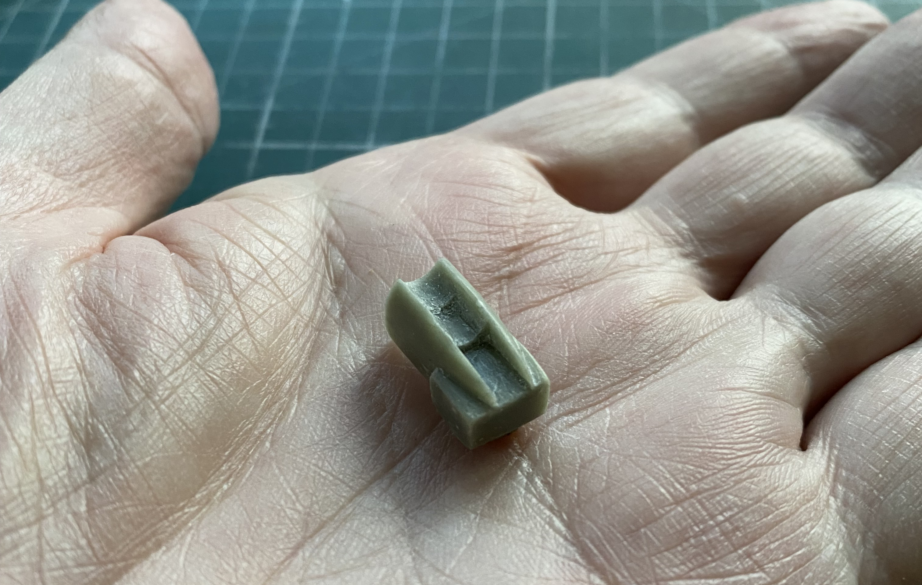

At this point I hit my first major snag. The front of this part has to fit over the engine’s bell-housing yet still fit inside the cockpit properly. This epoxy putty is great stuff and has lots of uses…and this ain’t one of them. I have to thin the sides out so much that they’ll become too thin to withstand the forces even a sharp knife produce. They’ll just snap off. I considered using my nifty Buffalo Model #15 electric dental drill but the same limitation applies. I need the sides to be about .020″ (.508mm) thin. If you want to see where that took me, you can click on this link: Old Dog, New Tricks, and 3D Printing
It could be quite some time before I get back to this build, as perhaps you’ll understand after clicking that link and reading what you find there.
