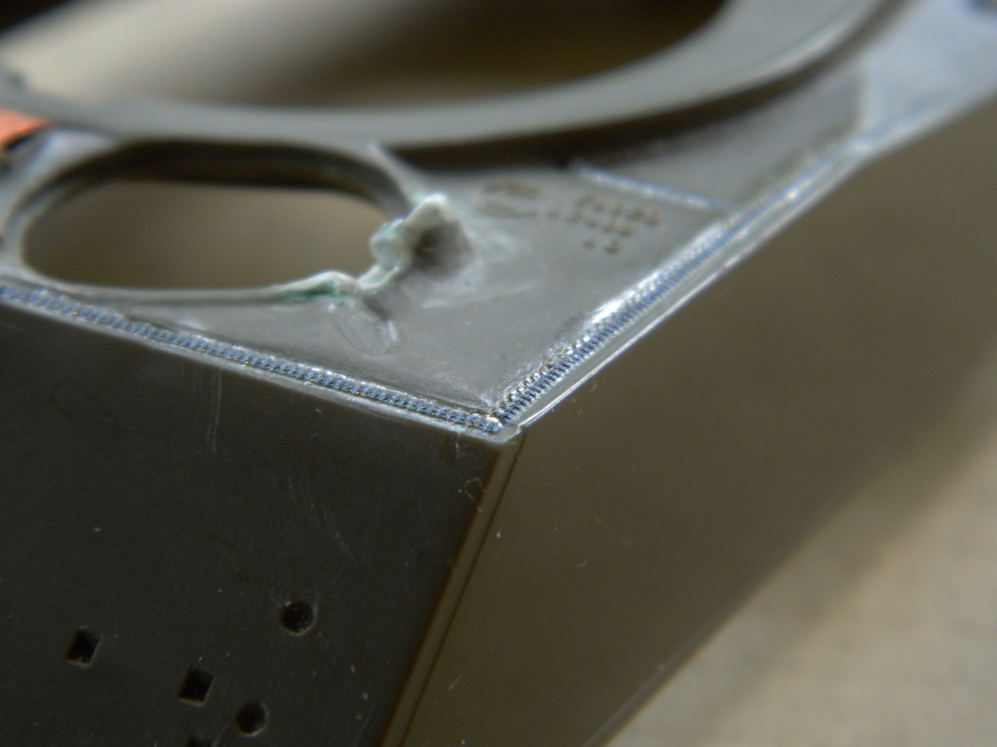
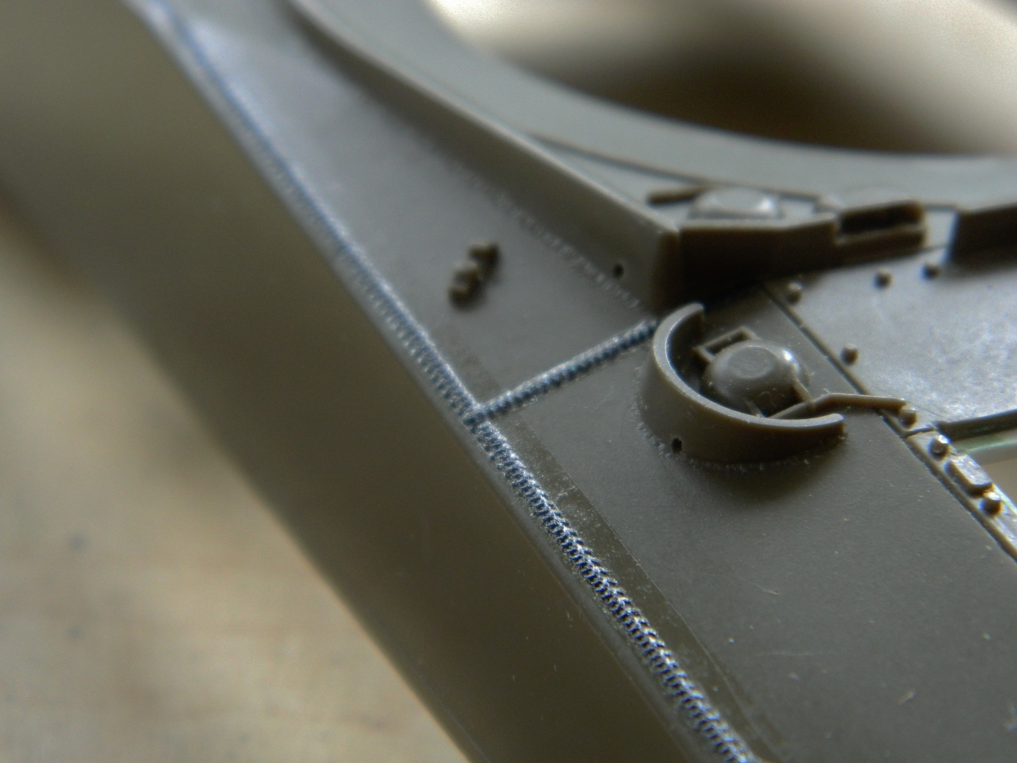
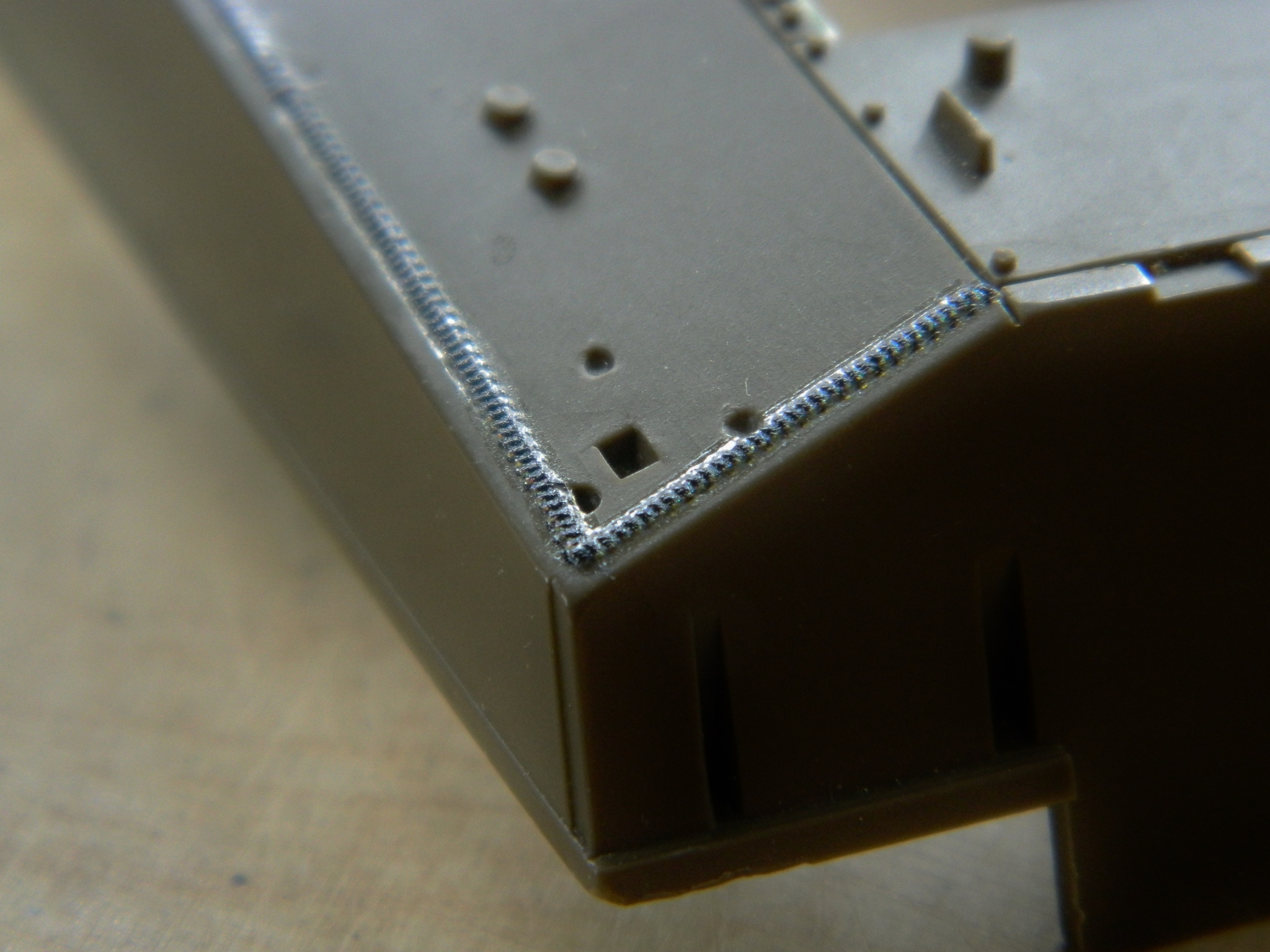
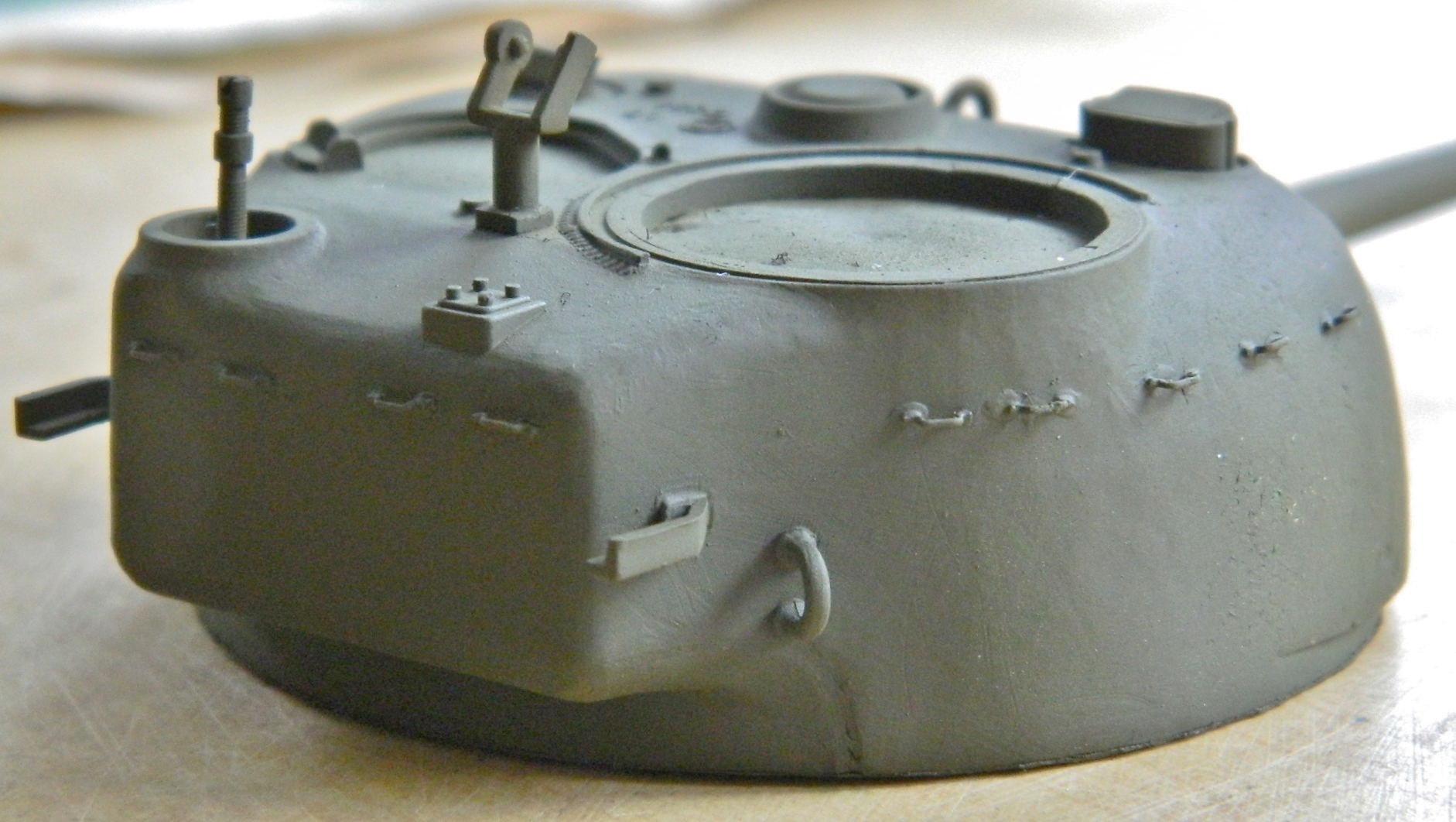
Tamiya got the weld beads wrong. On the kit they’re depressions and in reality they should sit above the surface. (This makes less than no sense to me. When cutting the dies, it would have been so much easier to cut the beads into the surface rather than to cut the surface down around the beads.) Archer Transfers makes 3D decals; resin details bonded to decal carrier film. They go on just like decals and though not perfect they’re a lot better. (As I worked around these beads, I discovered that I should have put them on later once I got to the point where I wouldn’t have to handle them much. They’re fragile and sections will easily pop off as things are added and the hull is handled). In order to more randomize the weld bead, I put down a wider bead first and then put a narrower bead on top of it:
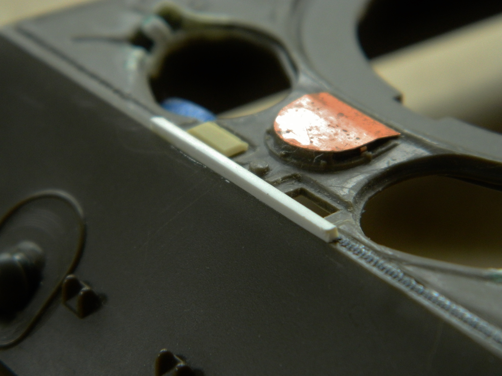
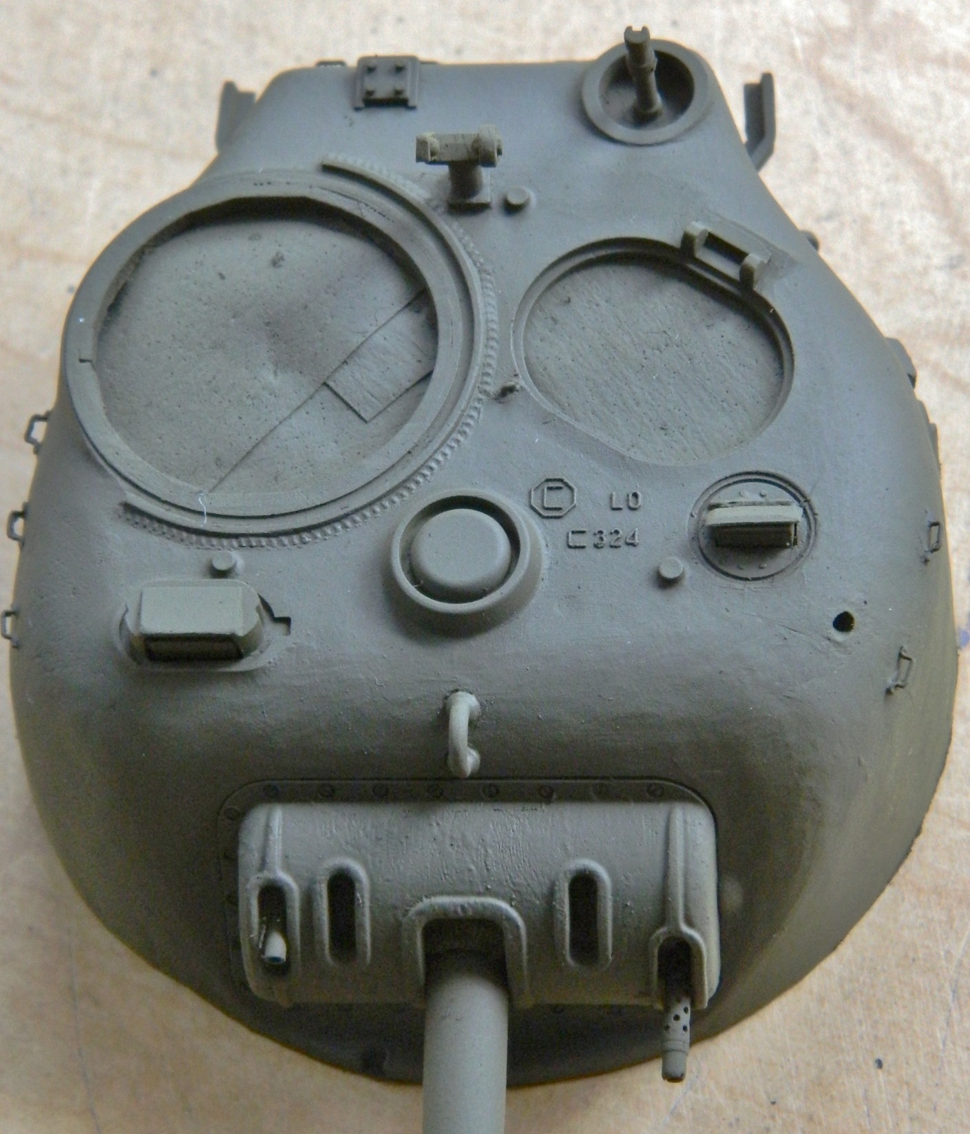
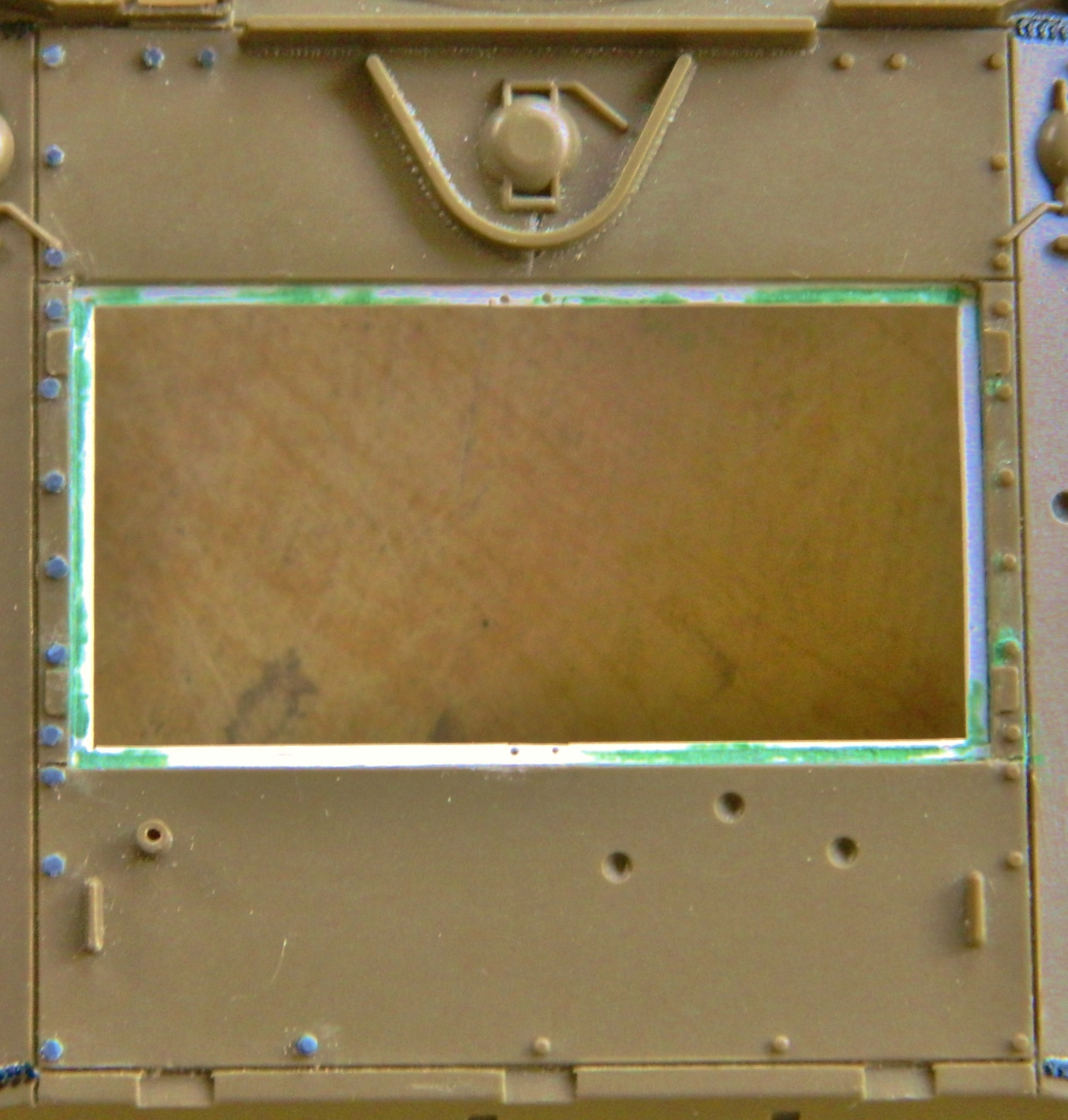
I added the splash guard in front of the periscopes and will trim it to dimension later:
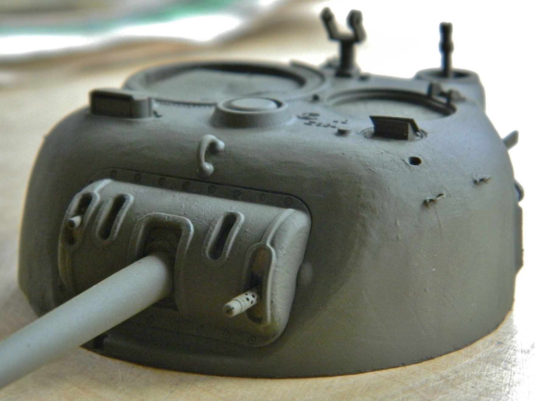
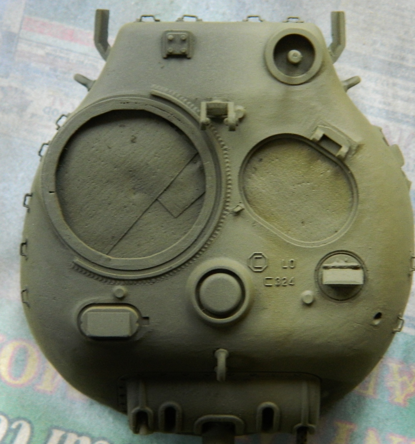
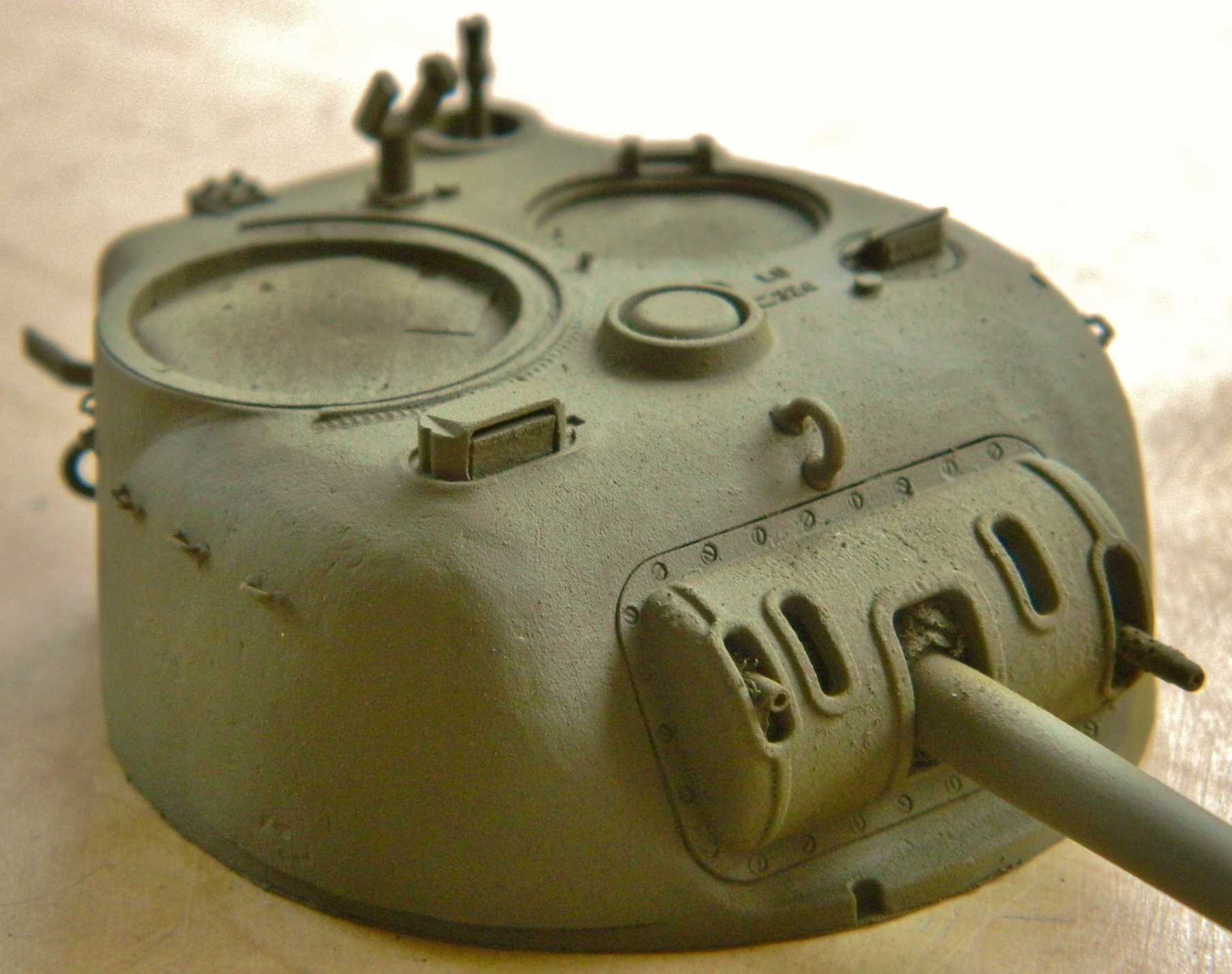
With those details taken care of, I threw a coat of paint onto the turret and other bits using Tamiya’s XF-62 Olive Drab straight from the bottle (and if you look closely at the gun shield you’ll see I added casting texture to it using the same method I used inside the turret, though I should have waited before shooting paint; there are more details I have to add):


Once the paint had cured overnight, I decided that Tamiya’s Olive Drab wasn’t quite the WWII OD green I wanted. I did some experimenting and hit on a color I’m satisfied with. I used six parts Tamiya’s XF-62 Olive Drab, one part Tamiya’s XF-3 Yellow, and one part Tamiya’s XF-2 Flat White (when mixing paints, I usually only mix paints of the same manufacturer together):
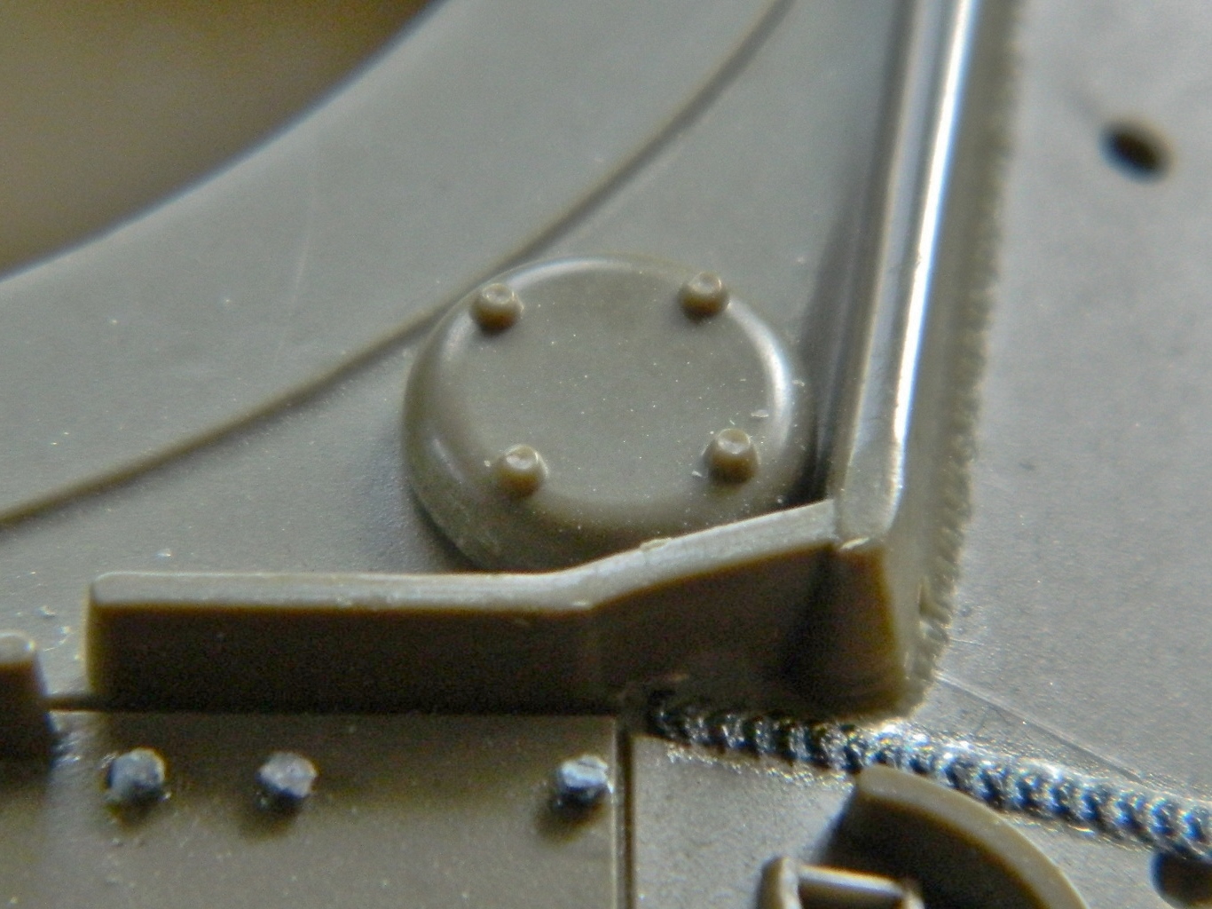
The rear deck plates of the hull are removable. But the “bolts” as cast on the model are round, not hex heads. Grandt Line bolts fixed that. If you look closely at the third photo down, you’ll see that as cast, the “bolt” is actually a nut on a bolt. To get them to be bolt heads, I file off the bolt protrusion and end up with a “bolt”:

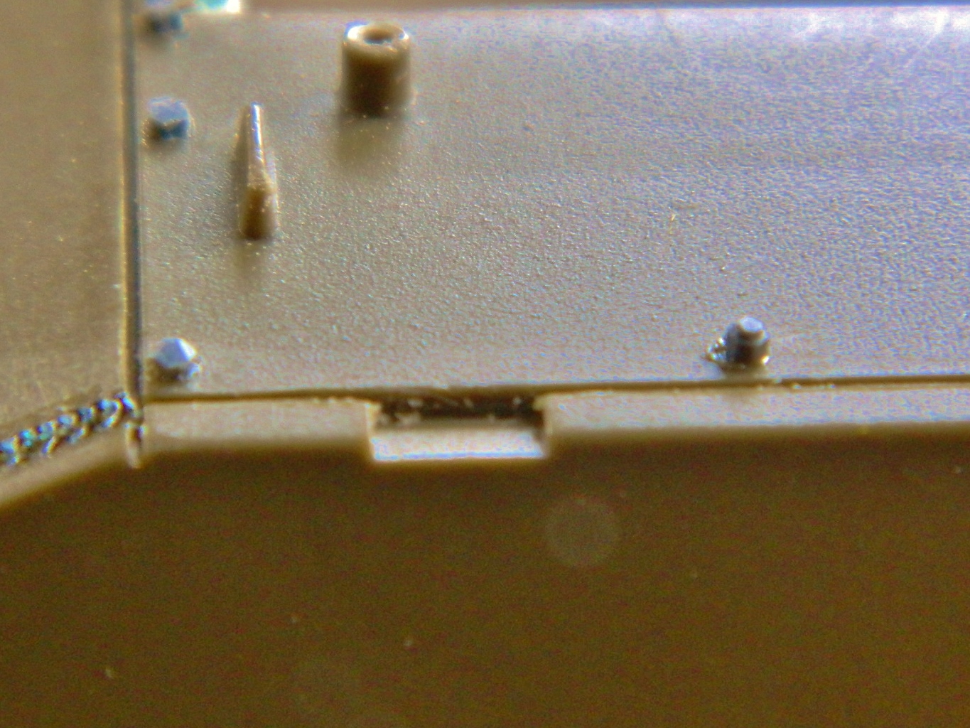
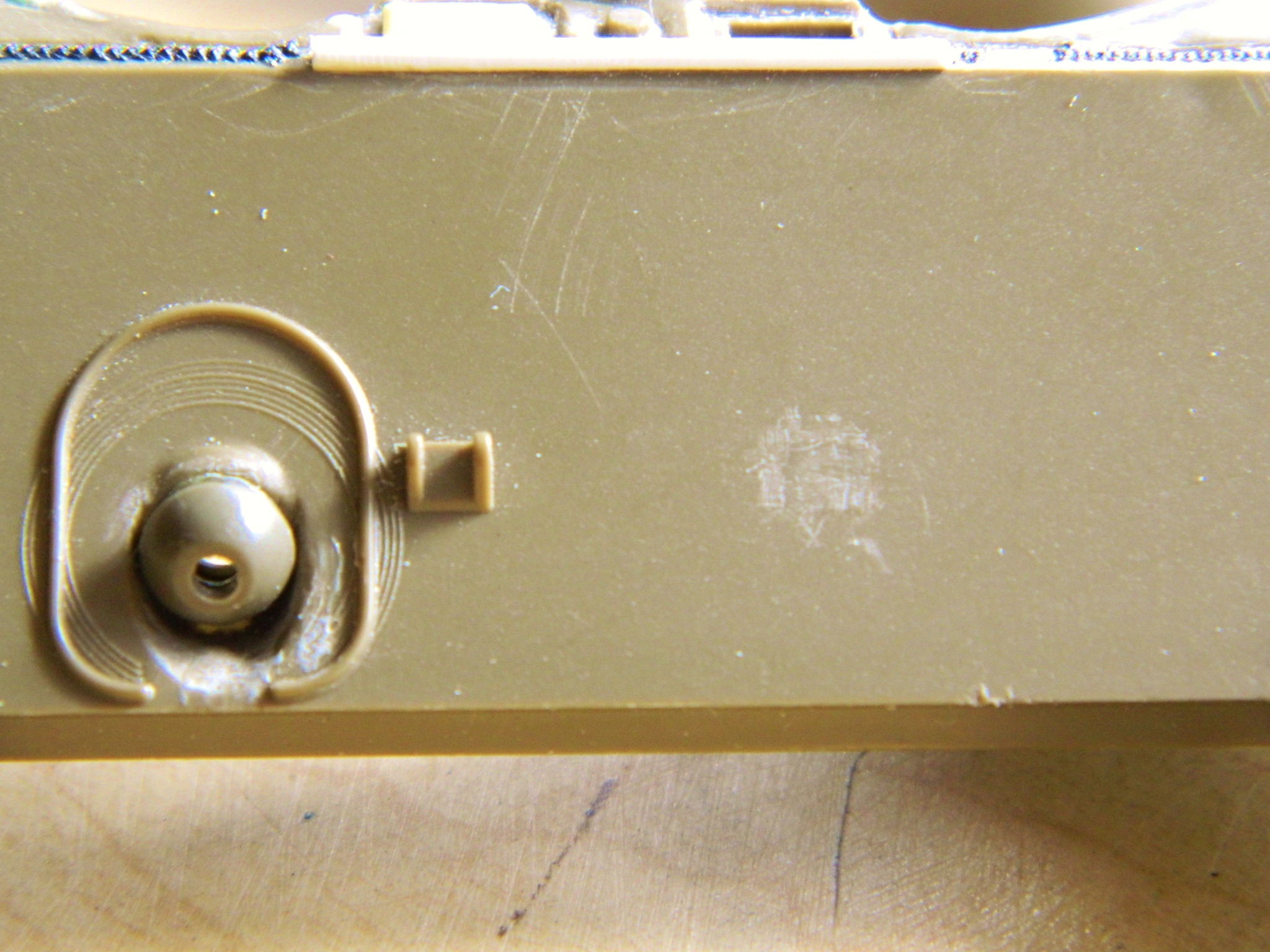
The rear ventilator cap suffered from the same problem with its bolts and got the same fix:

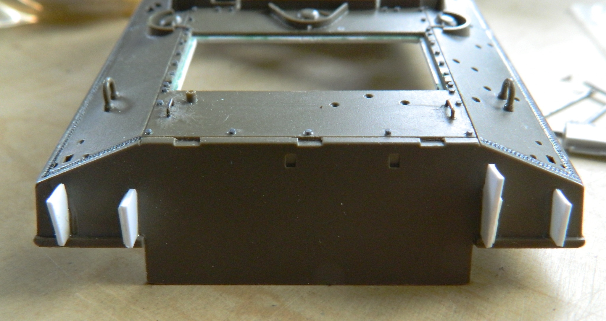
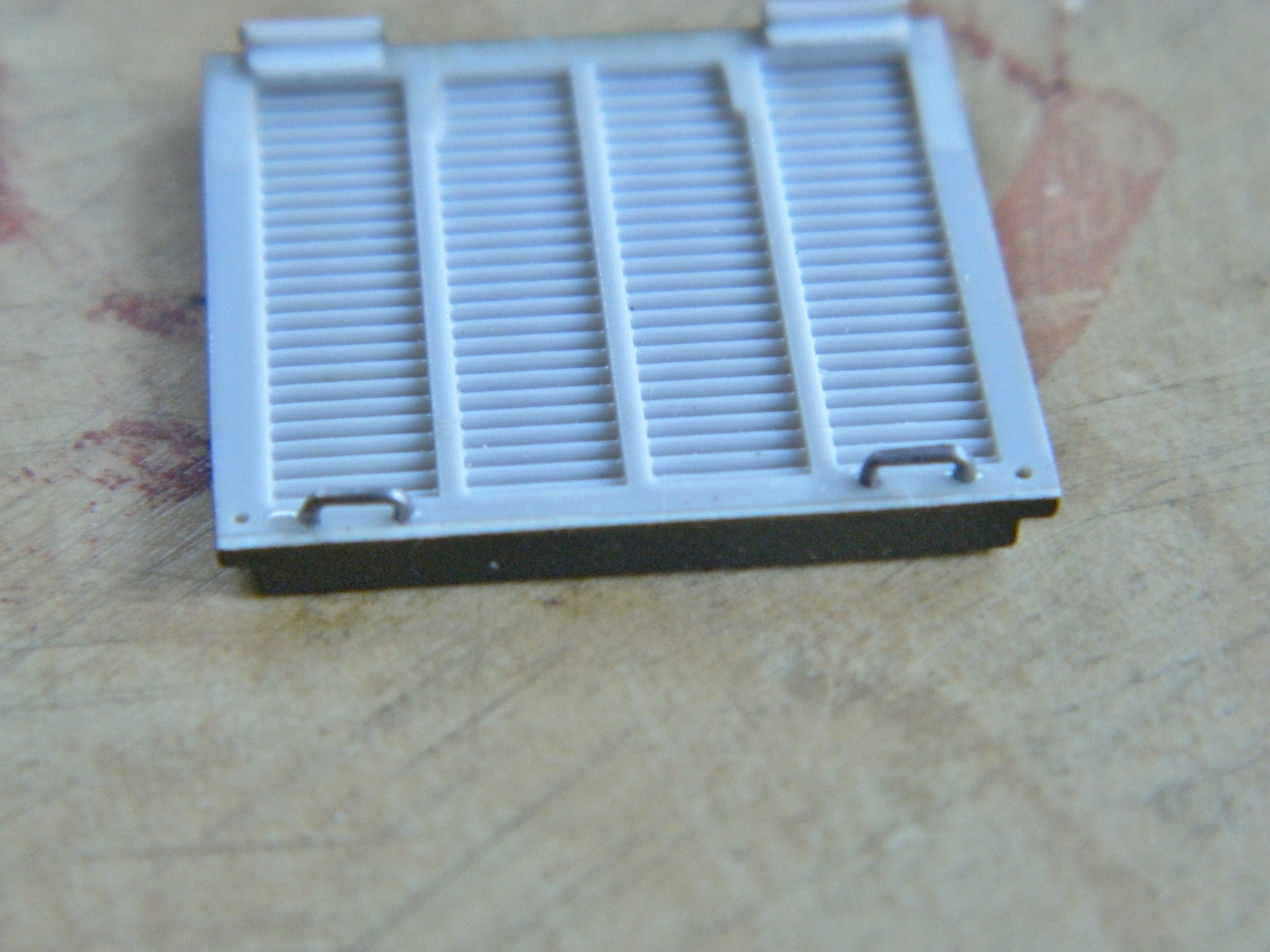
All the rear plates on top of the rear hull are removable and there are supposed to be grab handles where the kit has fins. Copper wire is cold-drawn which makes it hard and resistant to bending. I annealed the wire and replaced the fins with something more accurate:


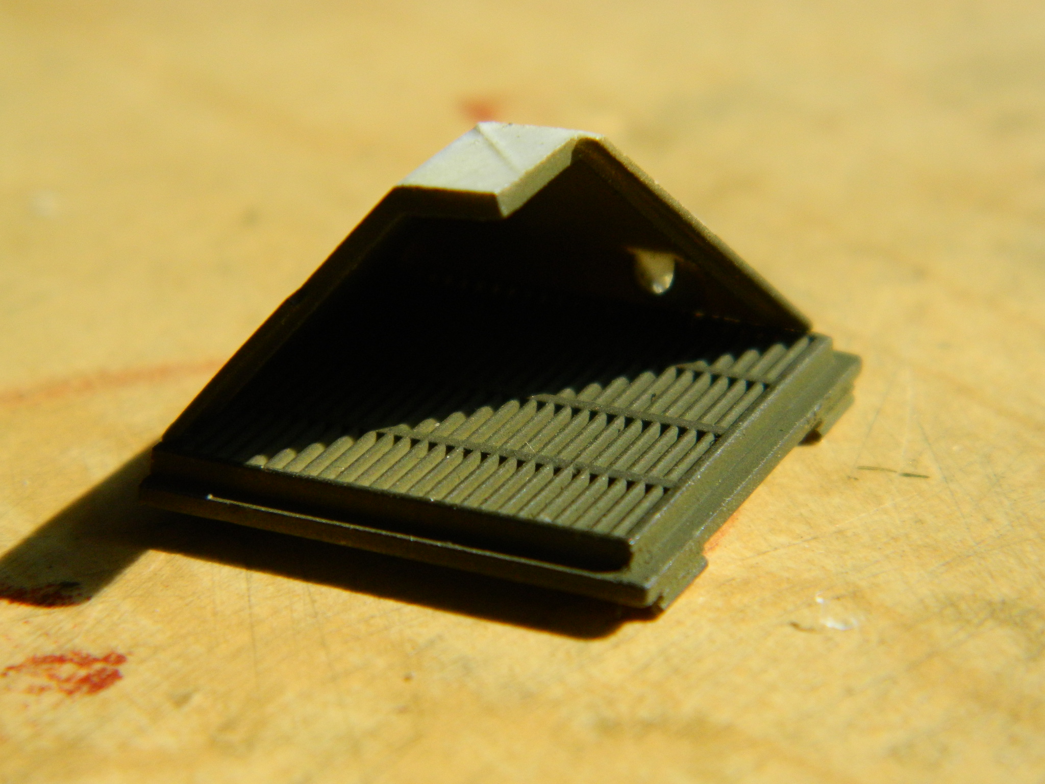
I tried doing the same thing for the grab handles of the engine covers, but even annealed the copper (successfully) resisted giving me the sharp bends I wanted so I used .020″ (.508mm) solder instead. I also added the rain baffles to the inside surface of the engine covers (all TMD parts):
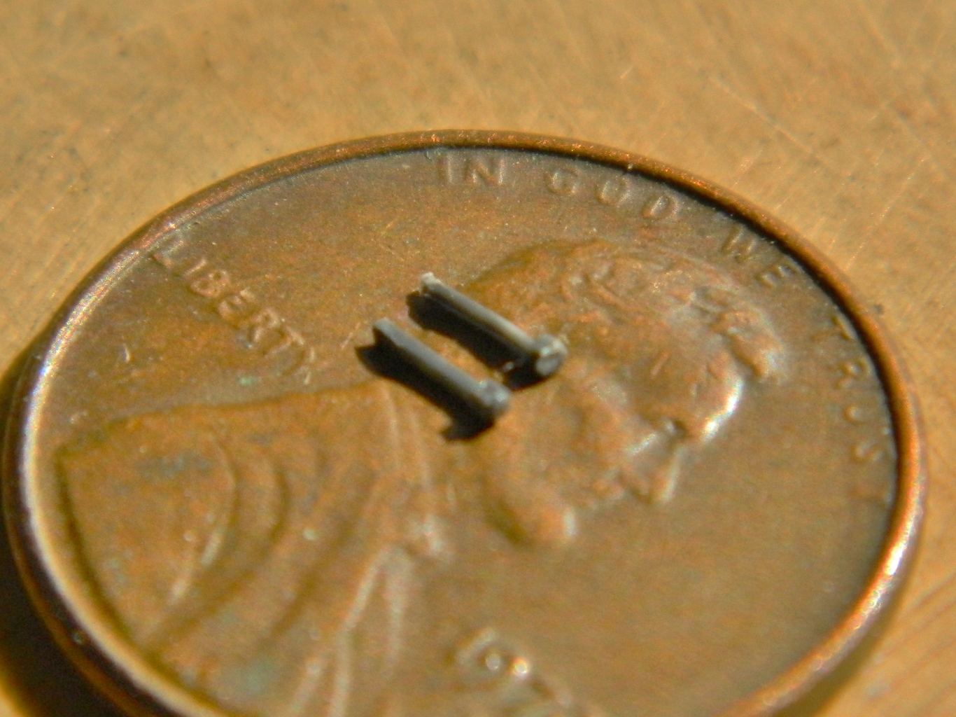
The driver and co-driver hatches were spring assisted to make opening easier. As it turned out, the similar springs for the loader’s hatch from my parts box(es) are just the size I want. I cut off the attachments for the loader’s hatch, added a Grandt Line bolt, and after cutting the inside of the hull to the appropriate angle, glued them in:

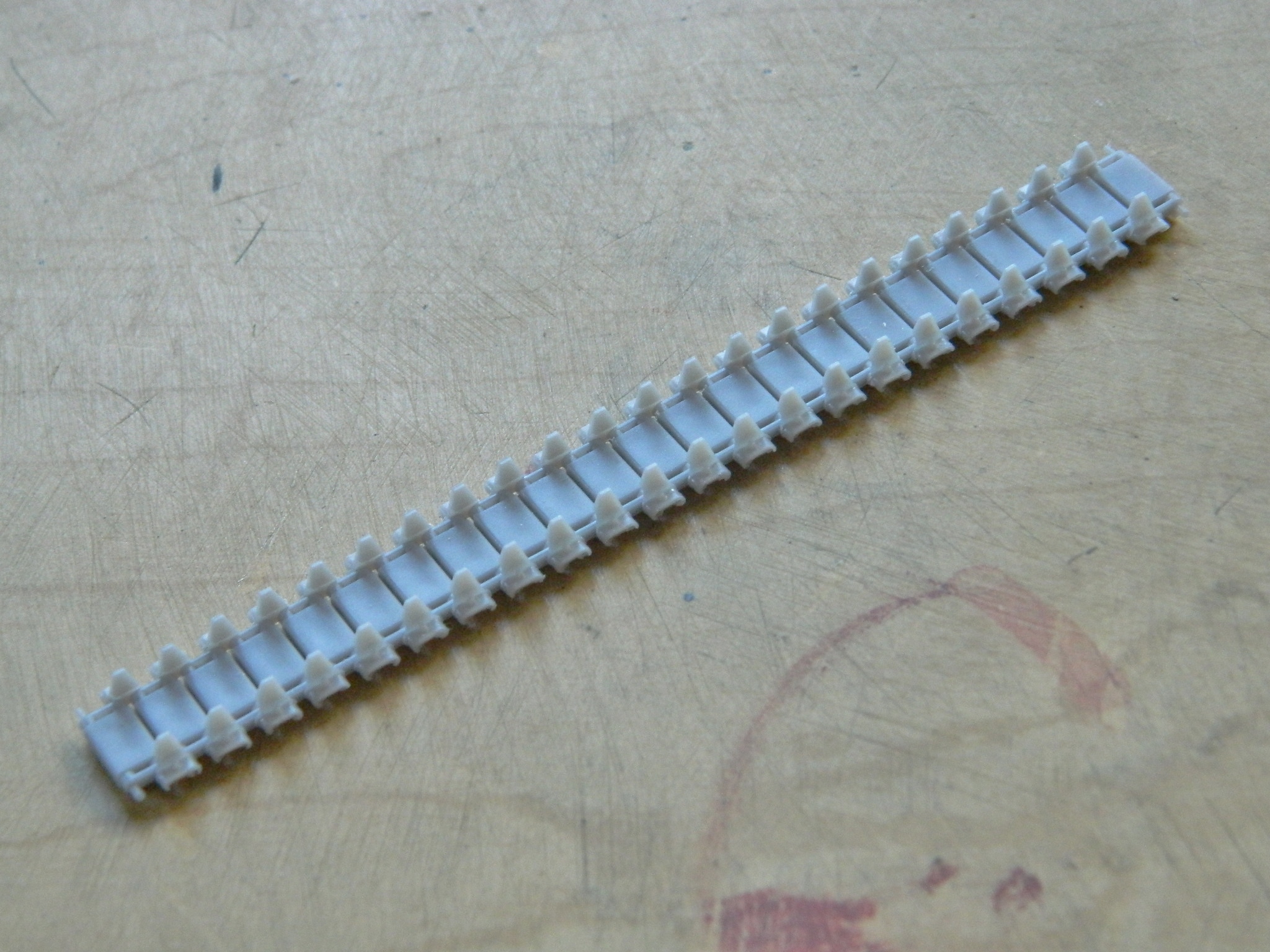
At this point I was waiting for parts and materials to arrive, so I decided to get after something tedious I wasn’t looking forward to. Assembling tracks one link at a time. This Sherman variant has 76 on each side. I timed it to take about 51 minutes per ten links assembled, so I’m looking at 16-20 hours to assemble both tracks.
Why am I doing individual link tracks? The “rubber band” tracks the kit supplies are vinyl and they don’t hold paint well. When flexed, the paint tends to flake off. The tracks I’m using are styrene and will keep the paint (not to mention look much better).
A quick note here about aftermarket tracks…
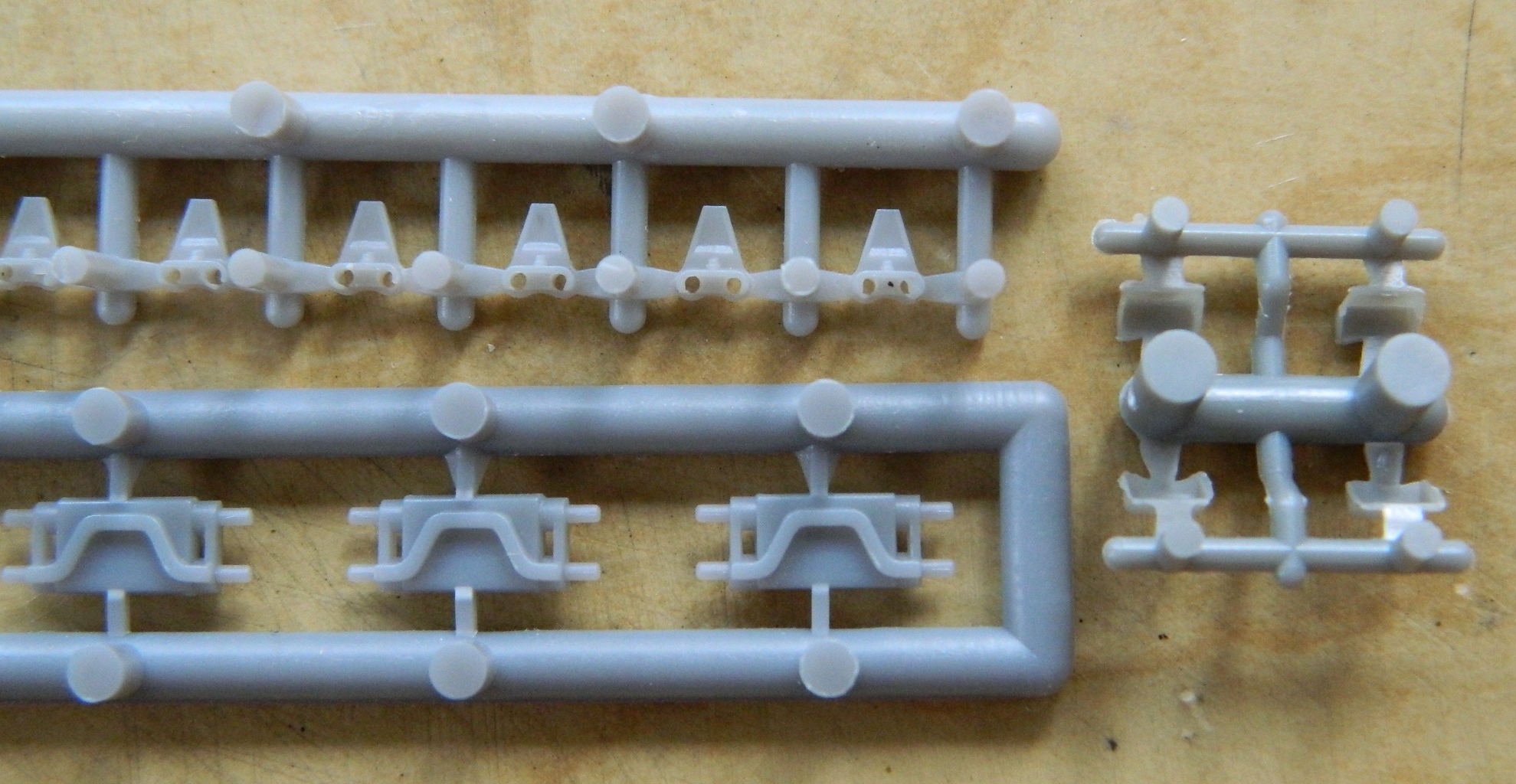
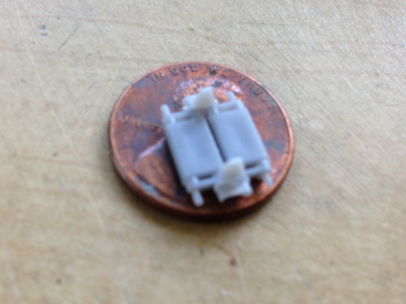
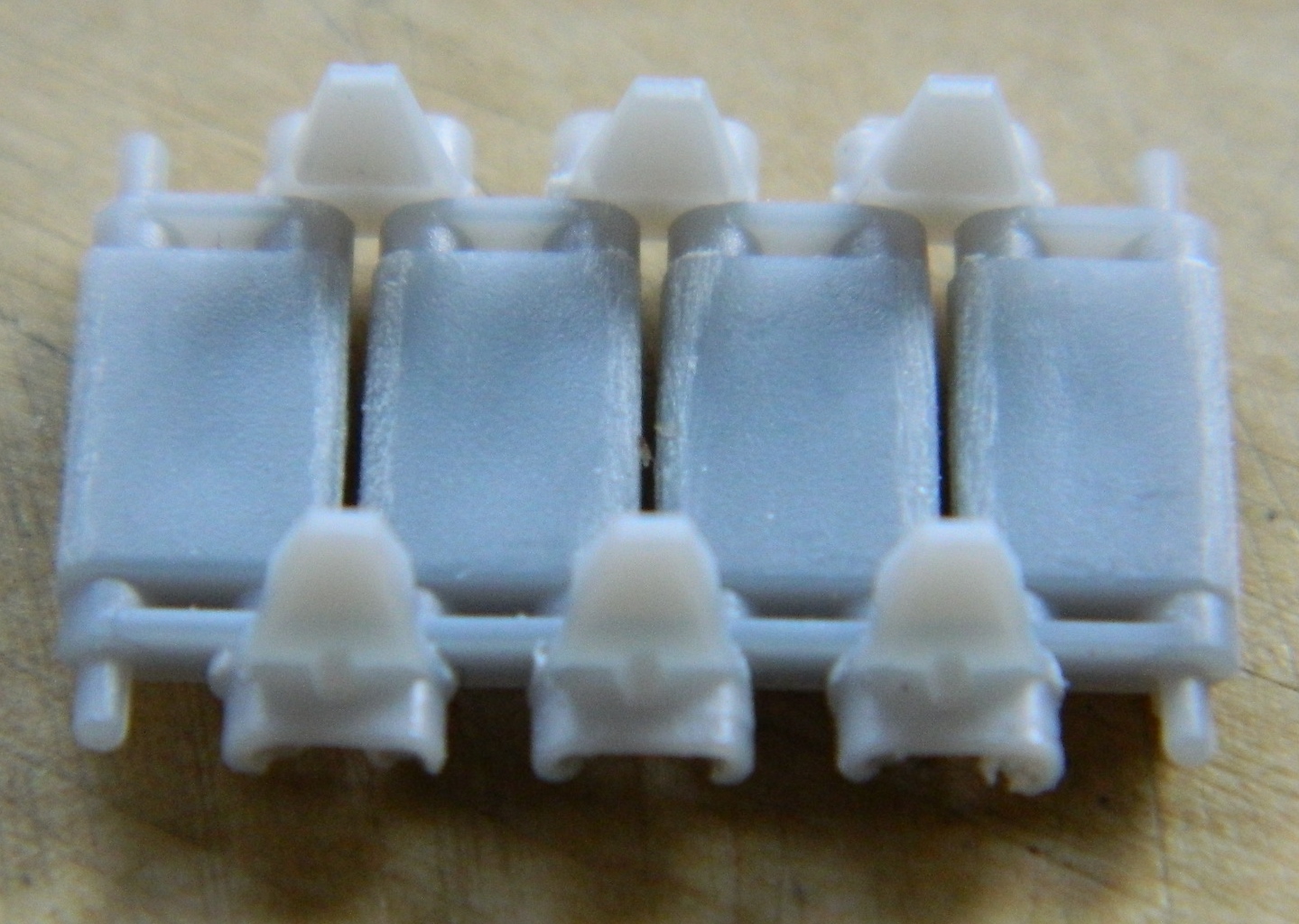
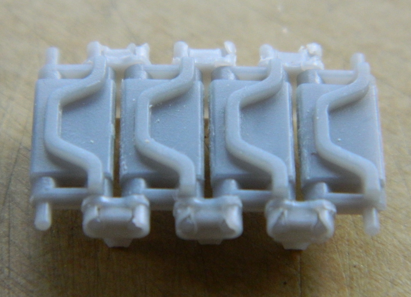
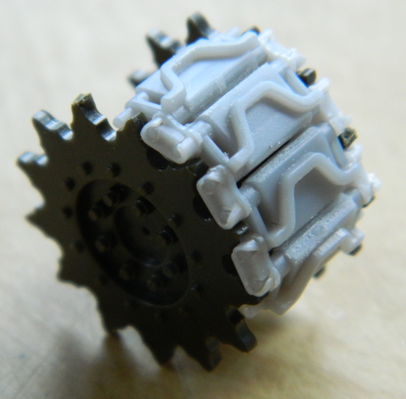
Before you buy tracks, look online for other modeling blogs and/or product reviews. Some tracks don’t fit accurately. From what I’ve been able to see, the place that tracks don’t fit seems to be the drive sprocket. Depending on which manufacturer you use, sometimes the drive sprocket wheel is too narrow for the width of the track to nestle between the sprockets. (Surprising me not at all, Tamiya seems to be more likely to have this problem, but it’s not exclusive to them.) But because of how the inner and outer Tamiya parts join together, it’s easy to widen the drive sprocket wheel by shimming the inside of the wheel. In this situation, I’m using the T51E, steel chevron tracks produced by Panda Plastics which happen to fit the Tamiya sprocket wheel perfectly. (In the first picture below, the sprue, or “tree,” on the right are “duckbill” track extenders and I tried to put them onto tracks but THAT level of tedium went beyond my patience to deal with so I’m not using them):
The good news is that I don’t have hair to pull out (anymore) over this.
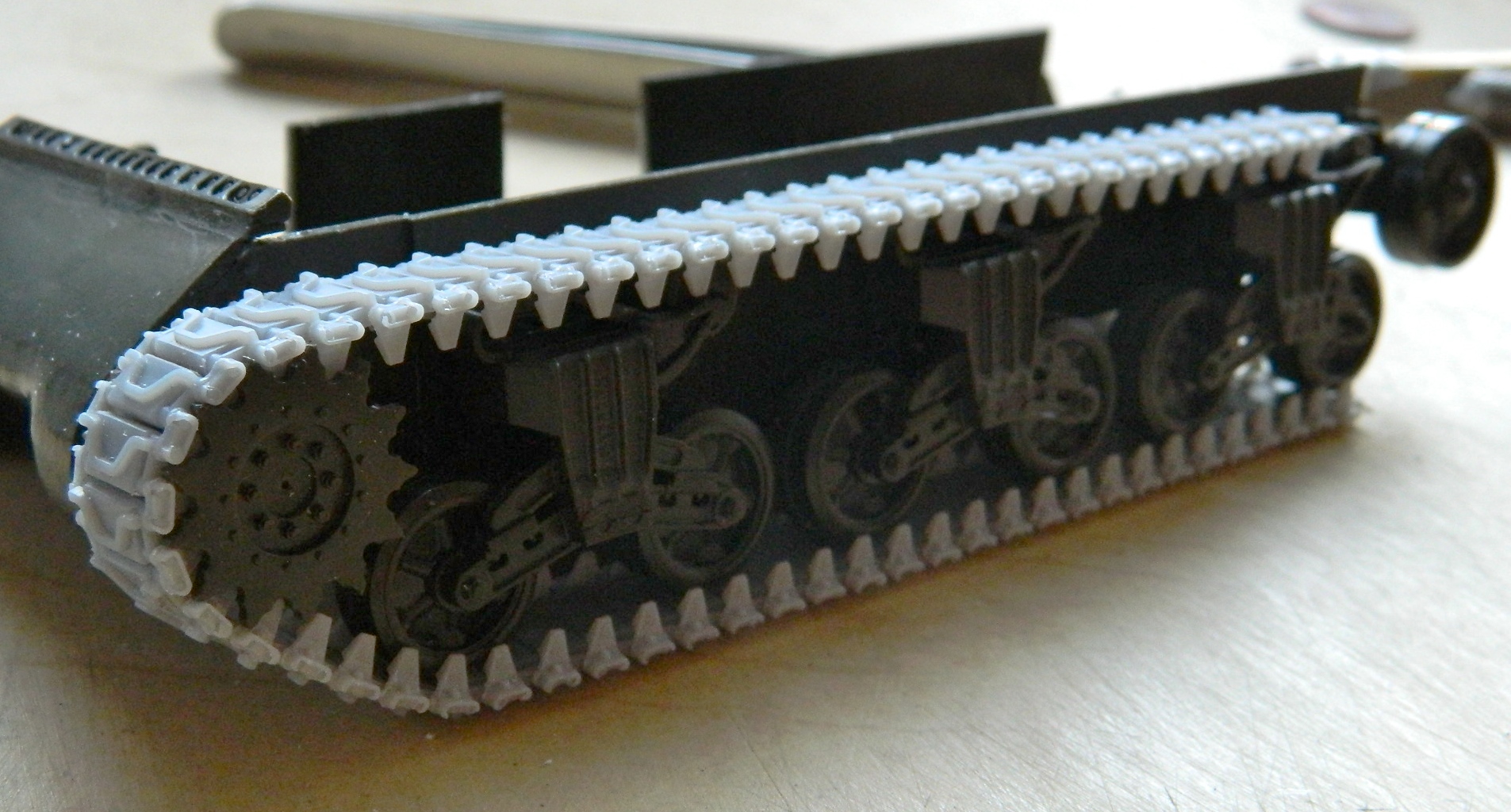
I threw the suspension of the spare kit together to use as a jig for fitting the tracks:


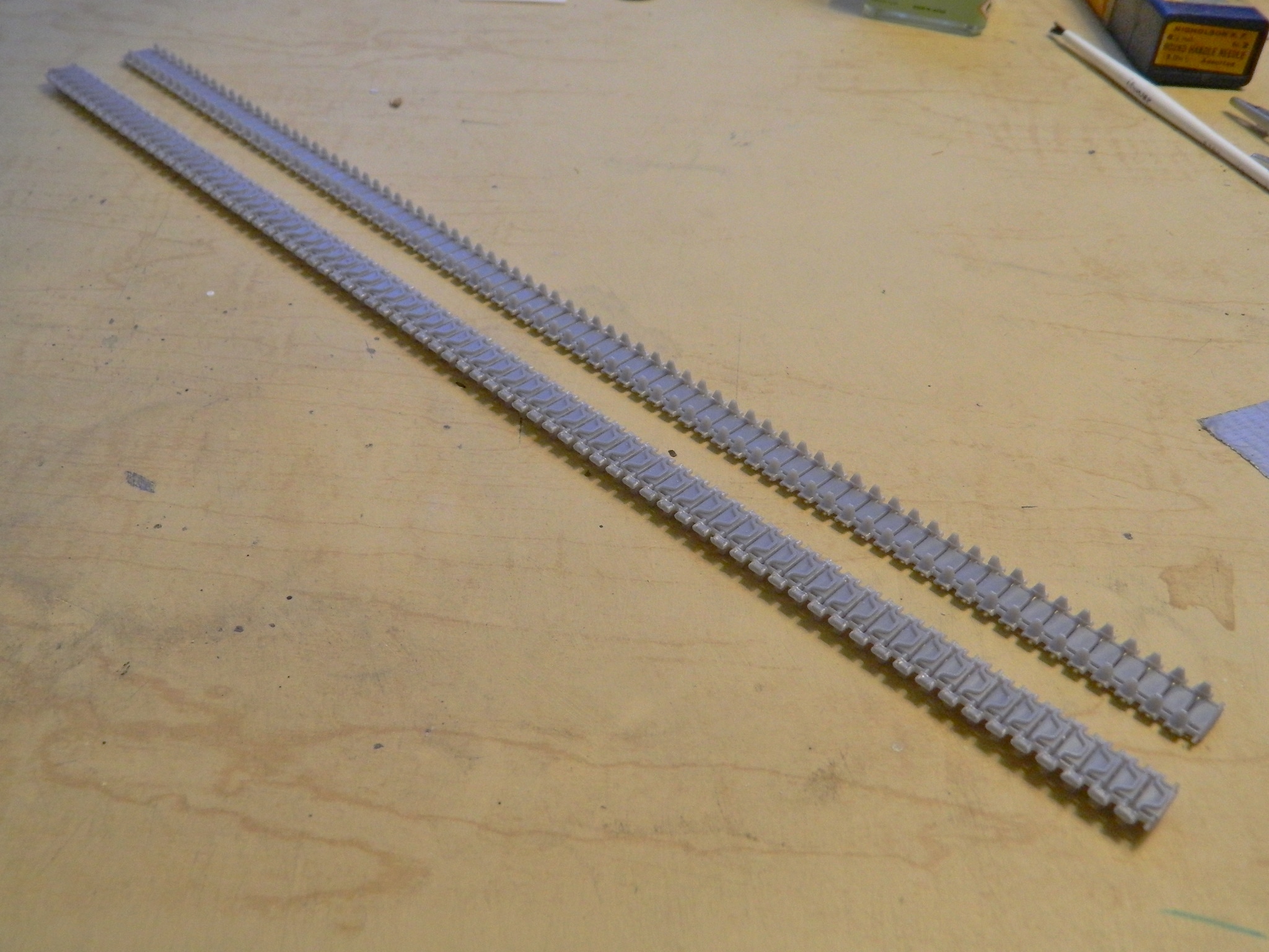
MANY hours later, I got both track runs assembled. Though Panda’s castings are clean with NO flash over the 152 separate pieces required to assemble the tracks, they are still cast pieces that have seams and each part needed those seams to be removed; it still took what seemed like forever to assemble them all. When I test-fit the tracks around the sprocket wheel, I noticed that the inner track face edges were just a little too square, so while I was removing seams, I also rounded the edges of each track so they would curve cleanly around the drive sprocket. (Hindsight has shown me that the next time I use individual track links that need edges rounded to round the edges of just the tracks that will bend around a wheel.)
Nothing is glued at this point (for reasons I hope are obvious). Test fitting shows me that I’m going to need at least three (preferably four) hands to put these things onto the suspension, but that’s a hair-puller for another time:
By this time I needed to do SOMETHING ELSE. During the many hours (did I mention many hours yet?) of track cleaning and assembly, I developed a case of what I call Craftsman’s Neck. That’s a lovely condition where your neck muscles PUNISH YOU for all the hours spent with your head hanging down working on something. So yeah…I needed to do something else.
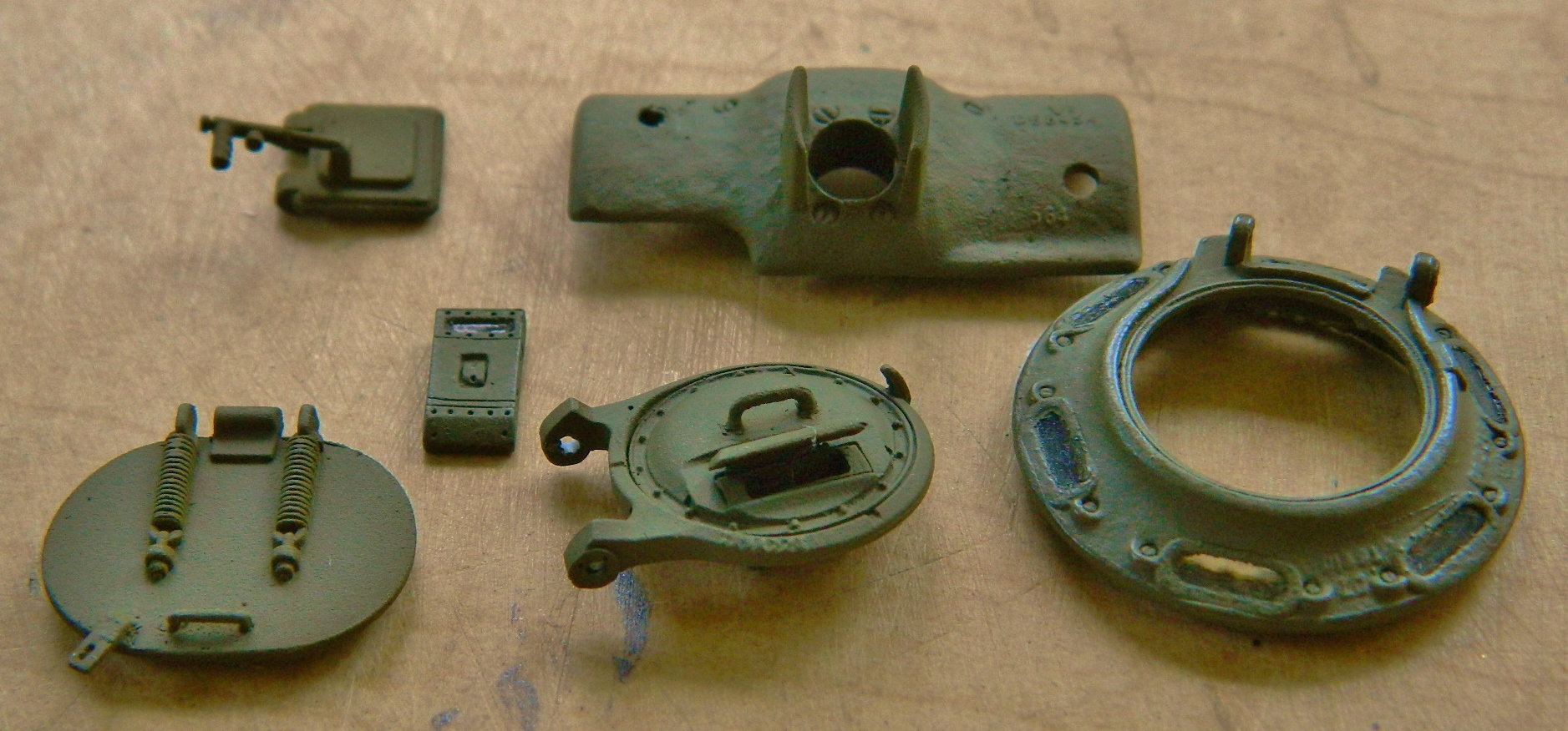
I decided to work on the vent blower assembly.
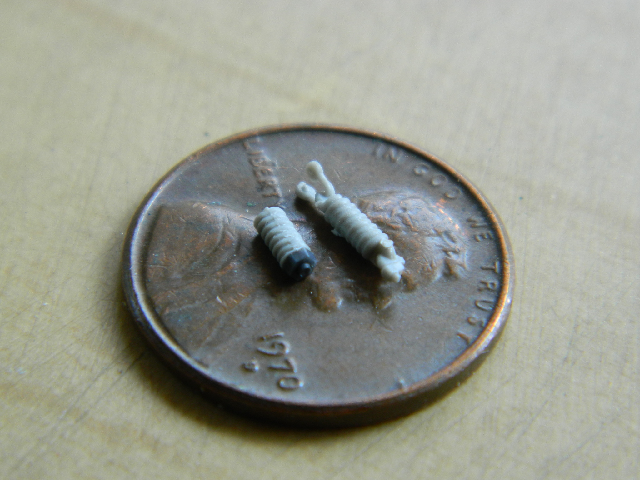
Originally I had made the master out of styrene. I guess I should have known better because I tried to take a short cut (yeah, I know…) around replicating this assembly. I ordered a reusable mold making compound from Micro-Mark. It gets heated in the microwave to turn it liquid (or close to liquid; when molten it has the consistency of cool honey). As I found out, thin styrene doesn’t like heat and the styrene master I tried to use this molding compound with caused the master to deform the styrene slightly (by melting…how odd for something heat-related). So I made the blower assembly out of sterner stuff. Brass.
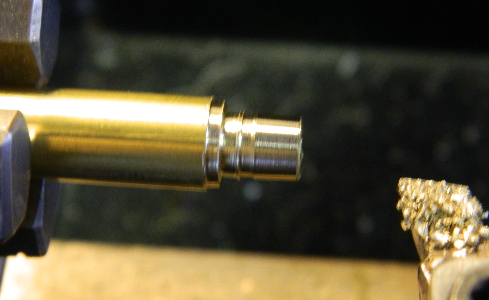
I purchased a 3/8″ (.015mm) brass rod from Online Metals, chucked it into my lathe, and turned the body:
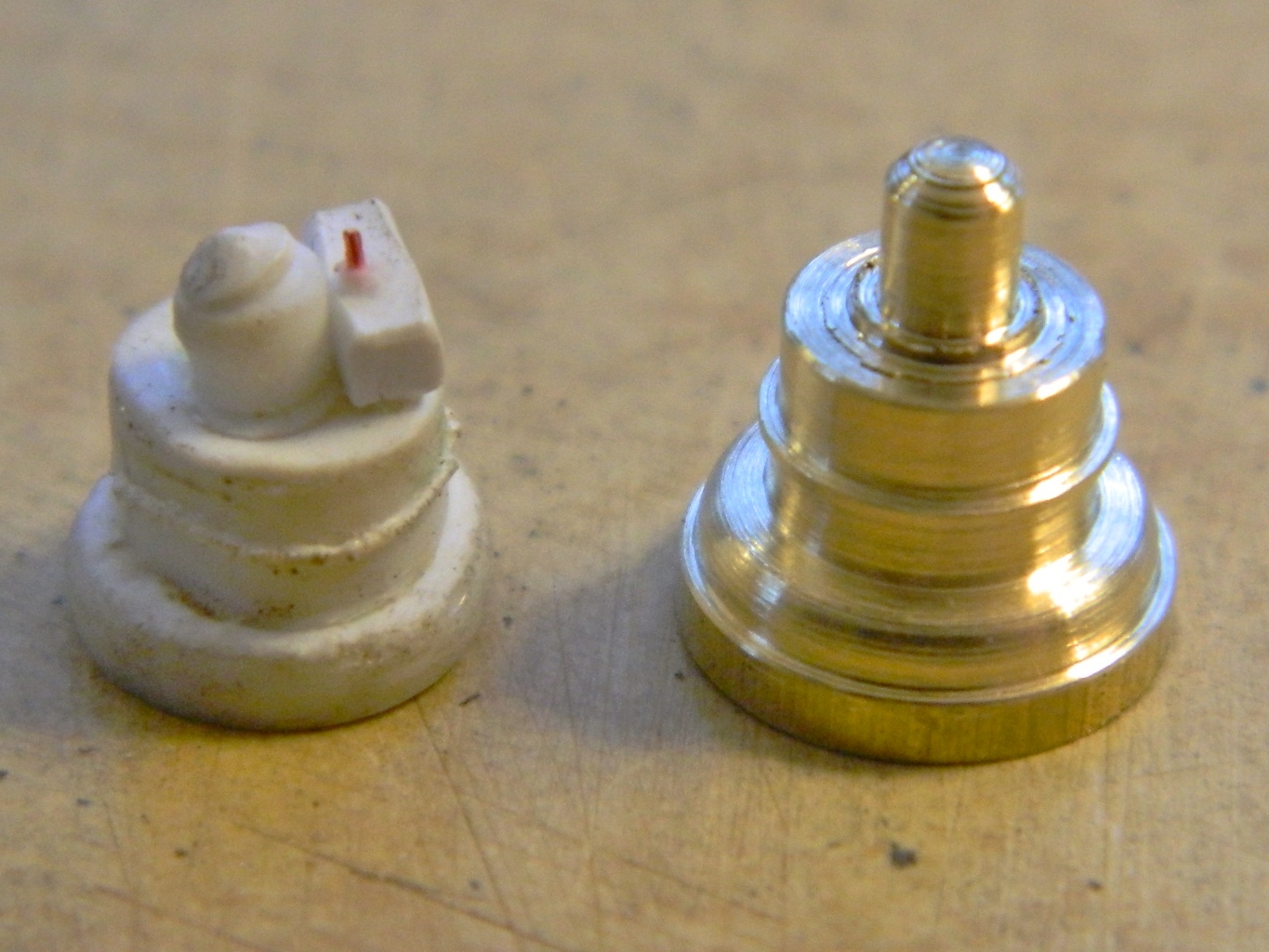
And because I’m essentially lazy, I snapped the switch box off the styrene master and glued it to my brass master:

So, since I’m going to be making molds, at this point I decided to go the route I should have gone to begin with and ordered two-part silicone molding rubber and to make a vacuum pump and chamber (an entirely different job and separate from this build, you can find details here Making the Pump and here Making the Vacuum Chamber). While I was waiting for materials to arrive, I decided to attend to a few other of the hull details, such as the crew hatches.
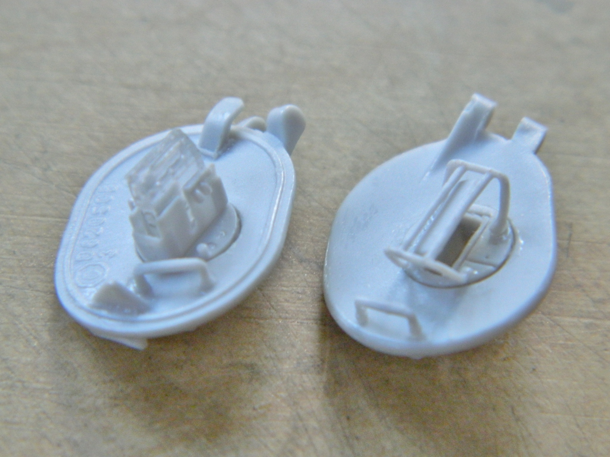
And again I turned to TMD for these very nice parts, having re-sculpted the hinges again so they would fit:

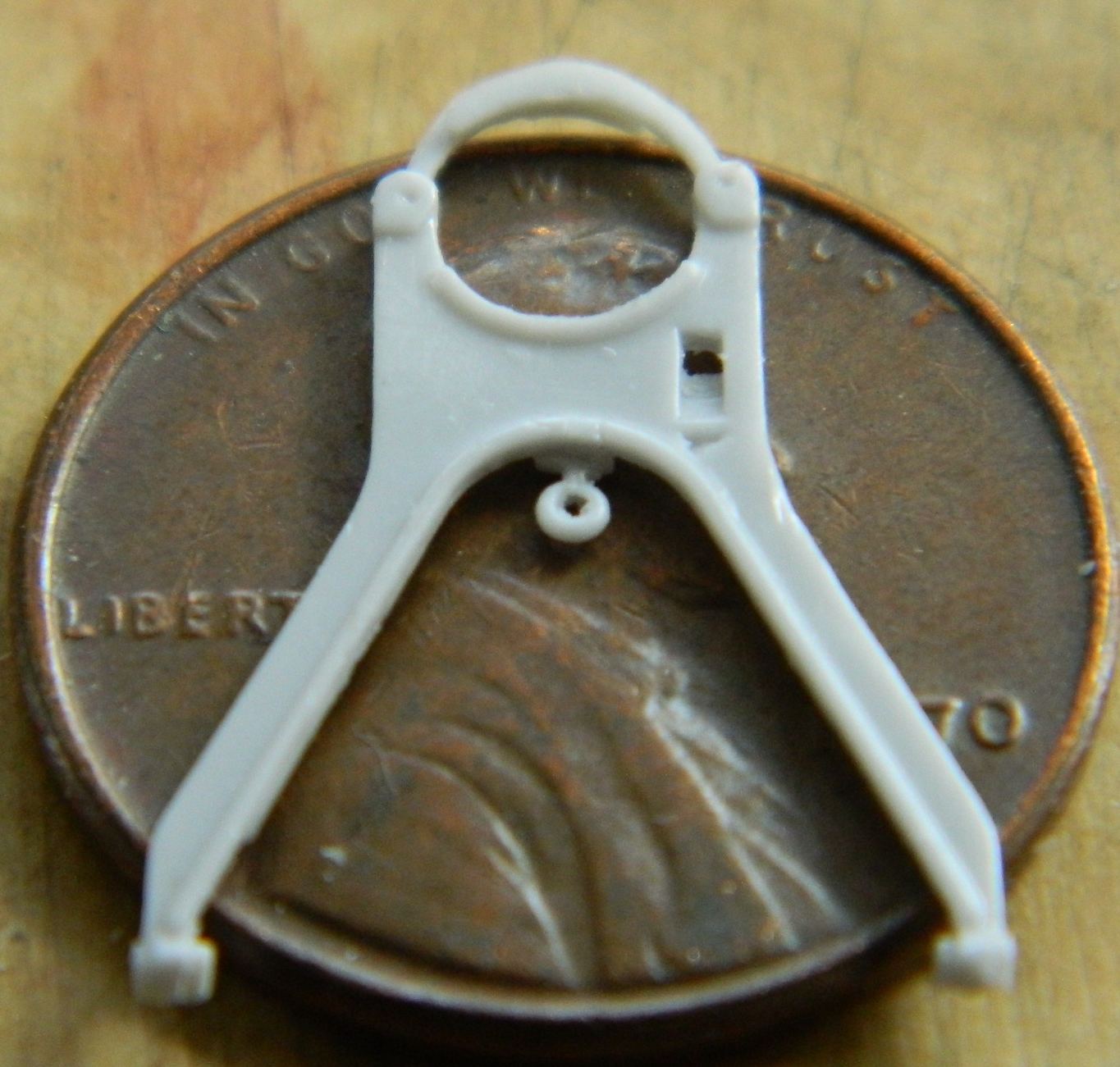
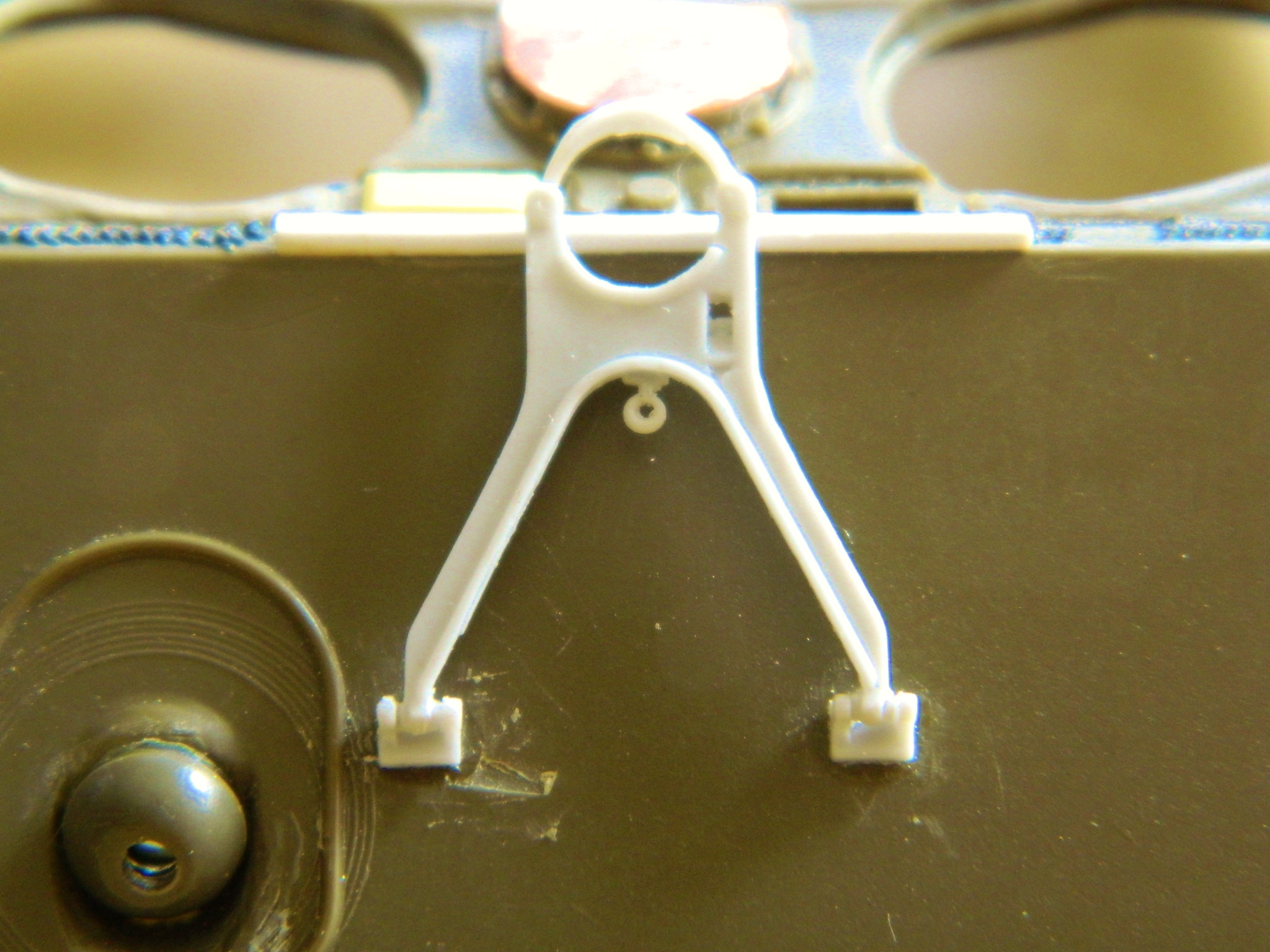
Then I replaced the travel lock for the main gun with more TMD parts:

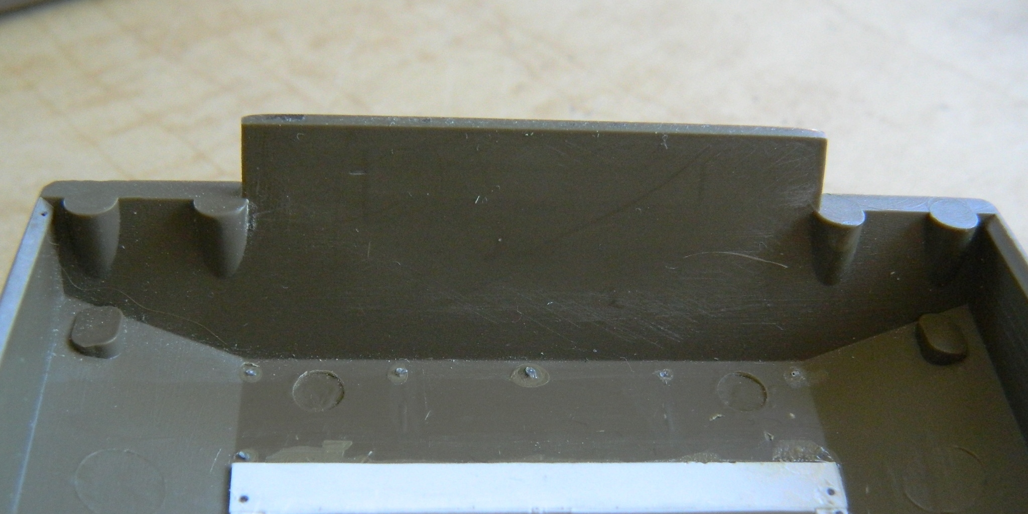
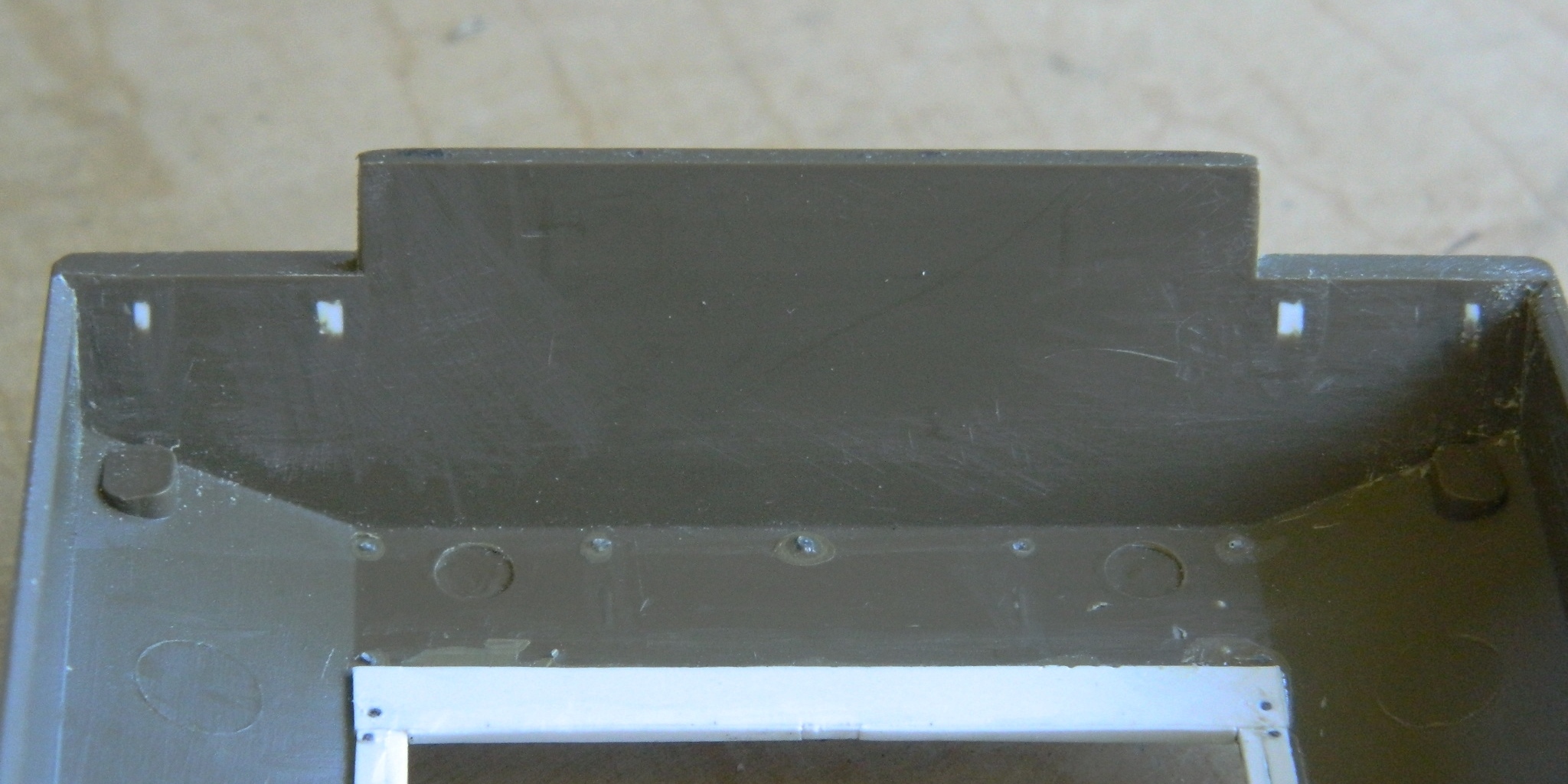
Since I will be replacing the kit’s storage brackets for extra track links with resin parts (TMD again), the slots in the rear hull face need to be filled and smoothed, inside and out (removing the provisions for the slots on the inside of the hull is going to make fitting sponsons later SO much easier):