Once I demolded the resin parts, I noticed that there’s a battery that sits on the shelf in front of the radio. It’s a prominent feature that wasn’t supplied with the detail set so I made one (and took a mold of it):

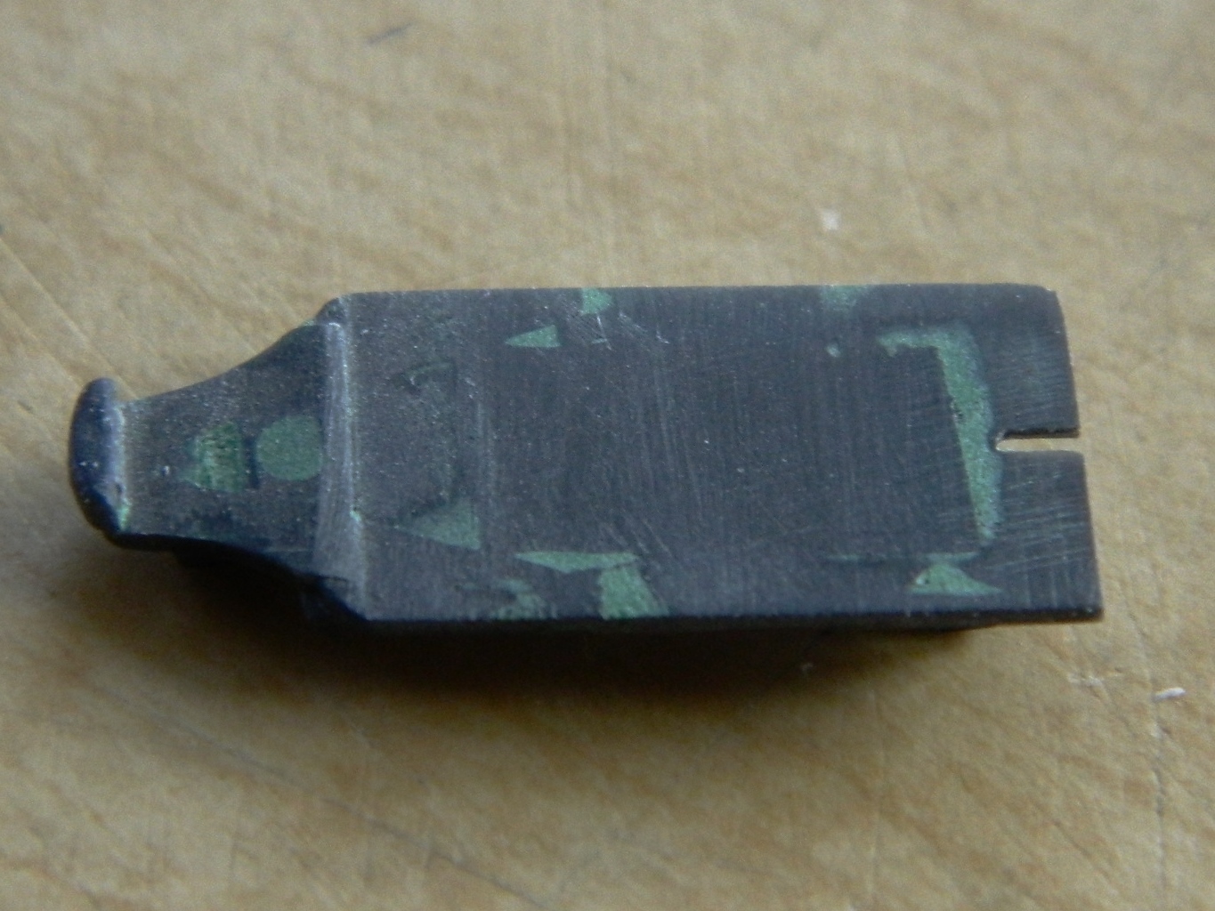
I’ve noticed that my (old) eyes are having difficulty with seeing the surfaces of the resin I’m using so I picked up some black resin dye. I was cautioned that it was highly concentrated so I tried adding a little bit. The effect, though better, wasn’t what I was looking for so I added a lot more. Below you can see the three pours; undyed on the left, lightly dyed in the center, and black on the right:

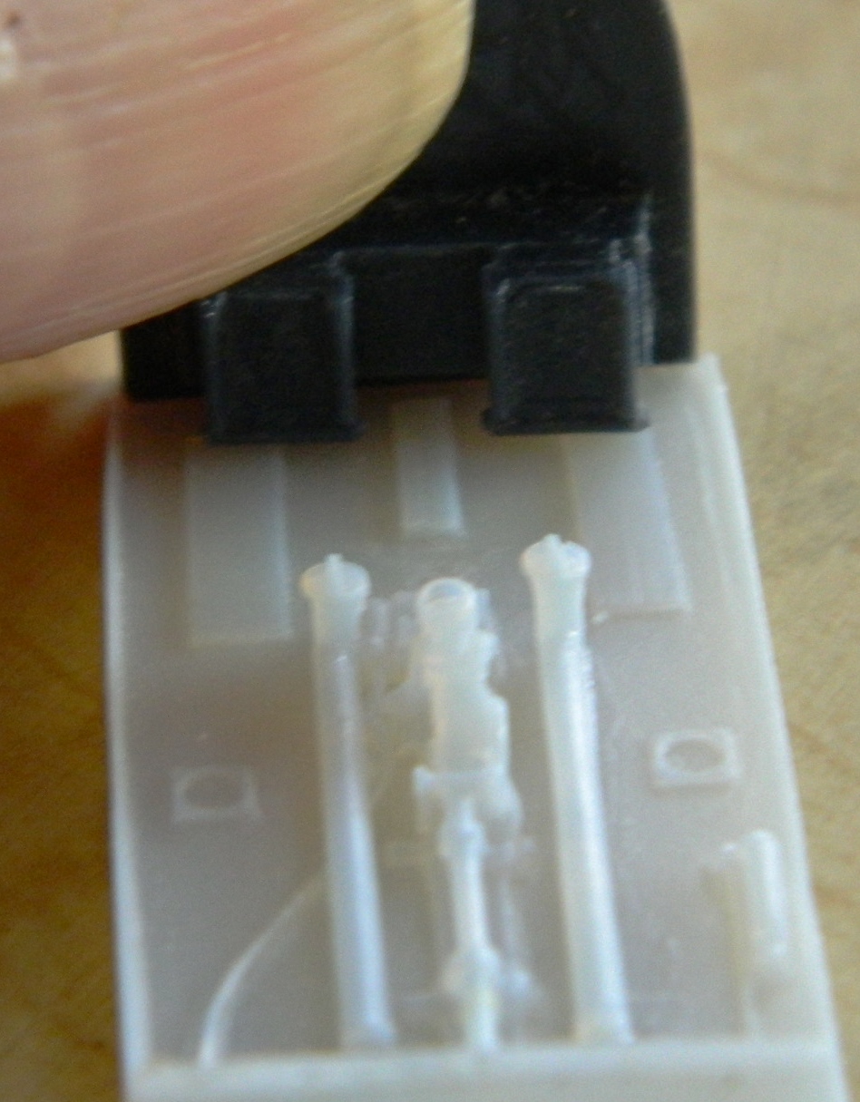
With the parts produced I want to use, it became time to start checking fit. The rudder pedals are a bit tight to the lower panel of the instrument panel but not so much that I’m willing to jump (crawl and stagger) through the hoops necessary to fix it. But the raised rectangles on the cockpit floor are skid plates for the pilot’s heels and as such should line up with the rudders…which they don’t, so that will need fixing:

In checking the resin seat against photographs of actual seats, the depression at the top of the seat where the shoulder harnesses are isn’t there. That’s an easy fix…just take down the corners:

Since I’m going to be using my rollover brace I carved/sanded/filed the brace molded to the armor plate off as well as removing the raised area on the back (from what I can tell from photos, that’s supposed to be flat). Once the molded-on details were removed, I applied a coat of putty to remove depressions:
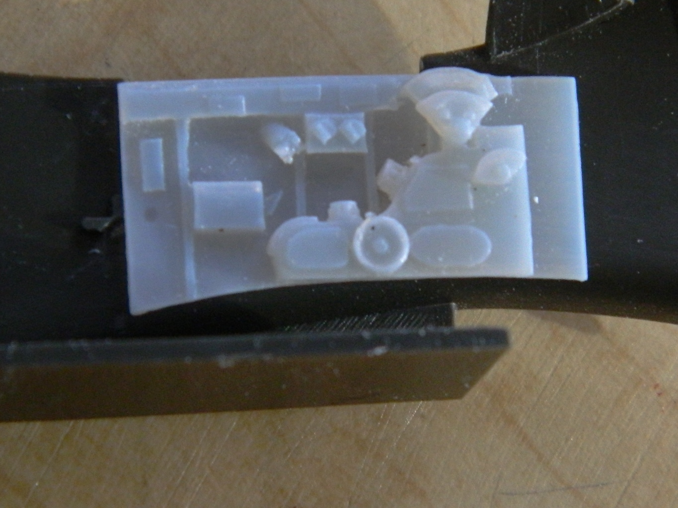
Not only should one always check fit, one should check often. Evidently the resin I’m using is very sensitive to heat, even the heat generated by warm hands (of which I have two). The photo on the left below shows that the curve of the “floor” (in quotes because the actual floor of the Allison P-51s is the top of the main fuel tanks) has flattened out. The part I’m holding (with my warm hand) over it is the side panel. The floor is supposed to follow the curve of that panel so I checked one of the side panels of the cockpit to make sure it was supposed to be curved that much…and it is. A quick session under hot water put the curve back that the floor is supposed to have:

I’ve decided to scratch-build an instrument panel instead of using the resin part. Any “detail” on the resin part is rudimentary and I want to kick that detail up. Since I don’t have quite all the gauge faces I’m going to need with the old Waldron set (pity they’re out of business), I ordered another set of gauge faces from Roll Model (I’m told they bought the rights to Waldron so it will be interesting to see what they have available).

OMG!!!
you truly are a world class EXPERT in all this stuff…wow!!!
>
LikeLike
Well, I dunno about either “world class” OR “expert.” I run across tidbits of information while researching things, though.
LikeLike
Wayne, I have an RP Toolz punch and die set http://www.rptoolz.com/?p=196. They also have a bigger set, not to mention a hexagon set for nuts, and I have one of their PE bending tools, http://www.rptoolz.com/?p=191. Pretty good kit.
LikeLike
Oh MAN! RP Toolz! THANK you for that resource! VERY nice looking stuff!
LikeLike