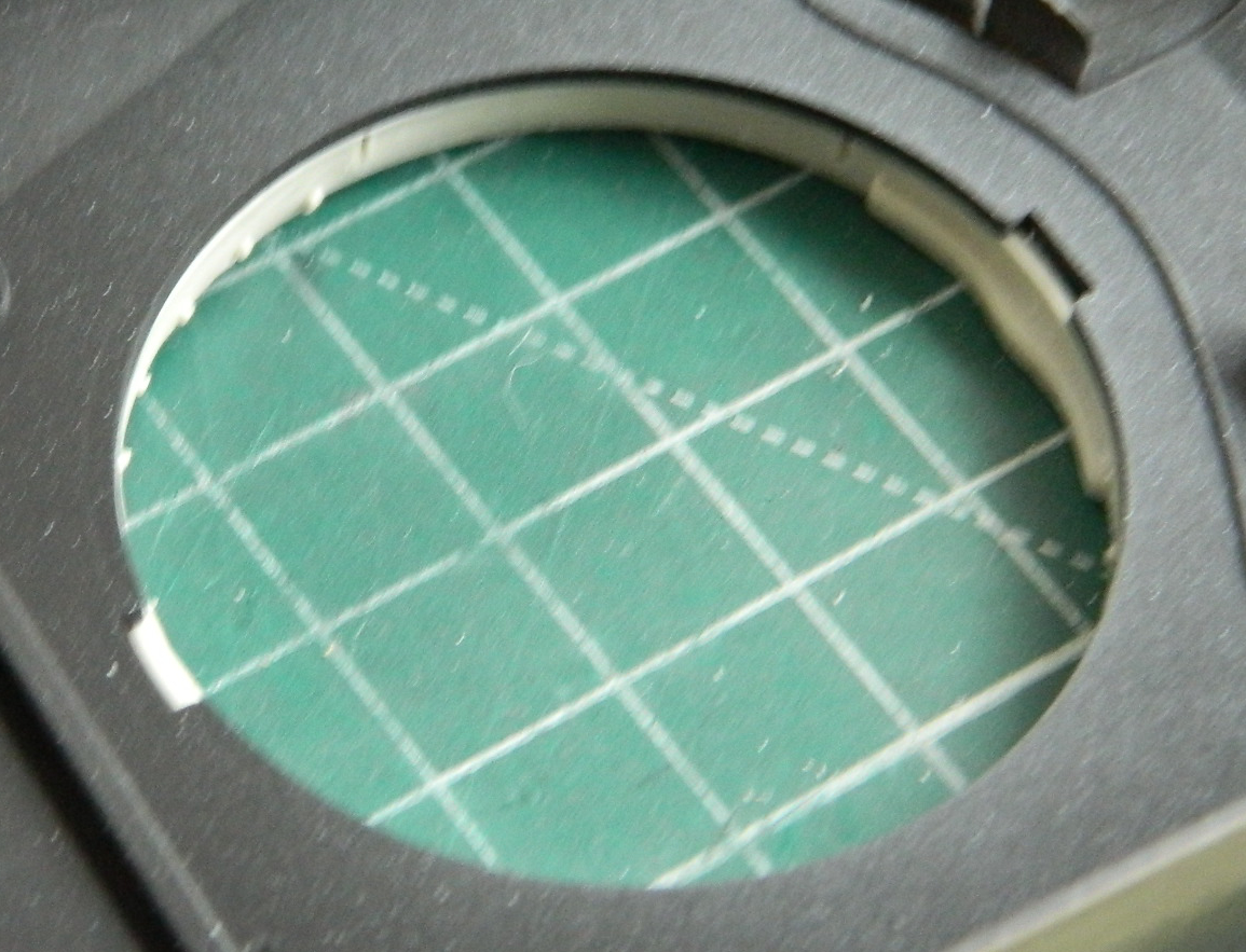
I left off with the turret being ready to have its clear panel installed, so (oddly enough) I started installing the clear panel. There’s only so much fitting that can be done because each time it’s fitted, there are subtle differences in alignment and at some point the thing just has to be glued in. I’m attaching resin to plastic so superglue is used:
Then the gaps around the clear panel get stuffed with scrap styrene, primarily 0.005″ (.127mm), 0.010″ (.254mm), with a bit of 0.020″ (.508mm) for diversity:

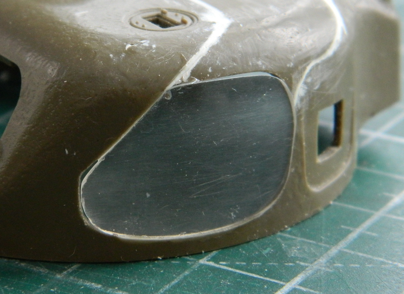
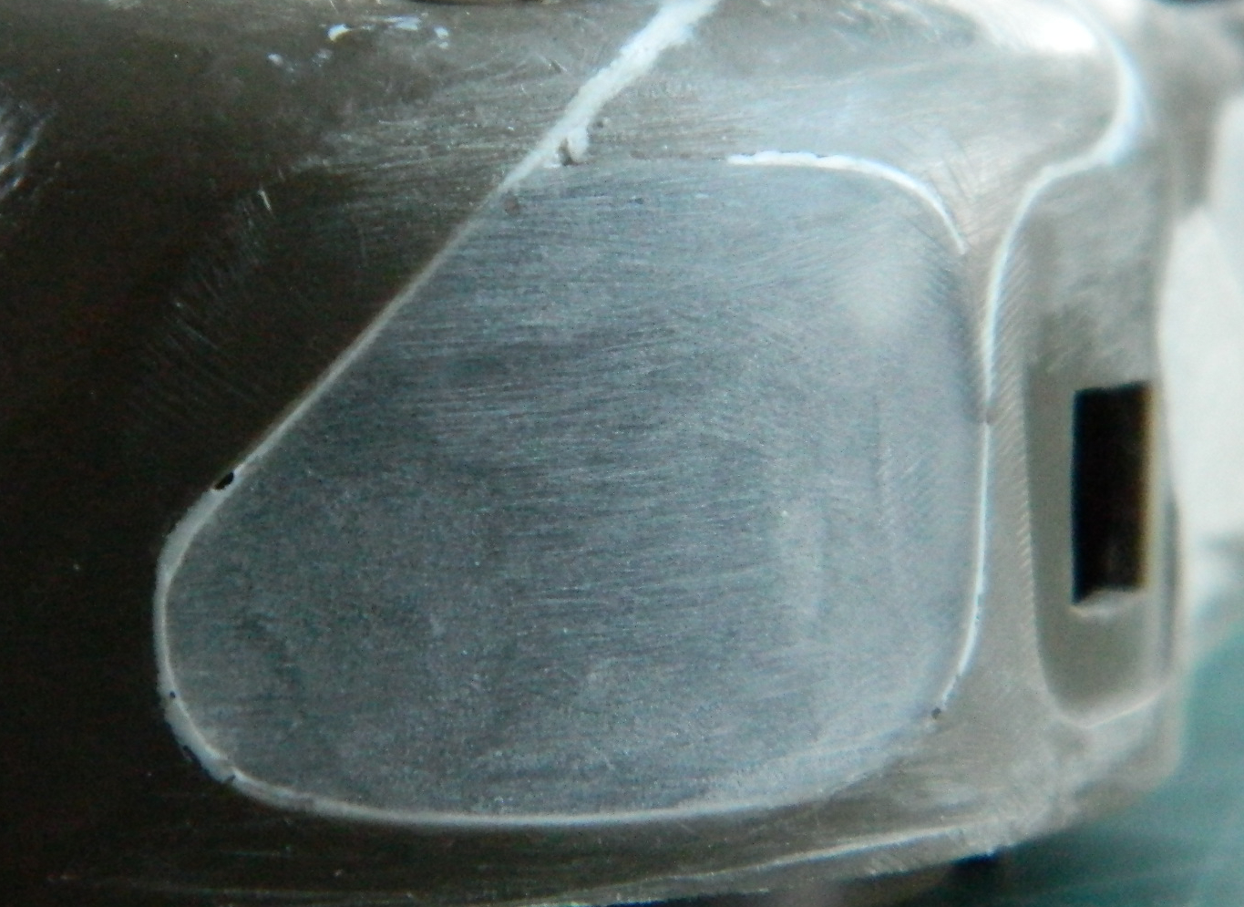
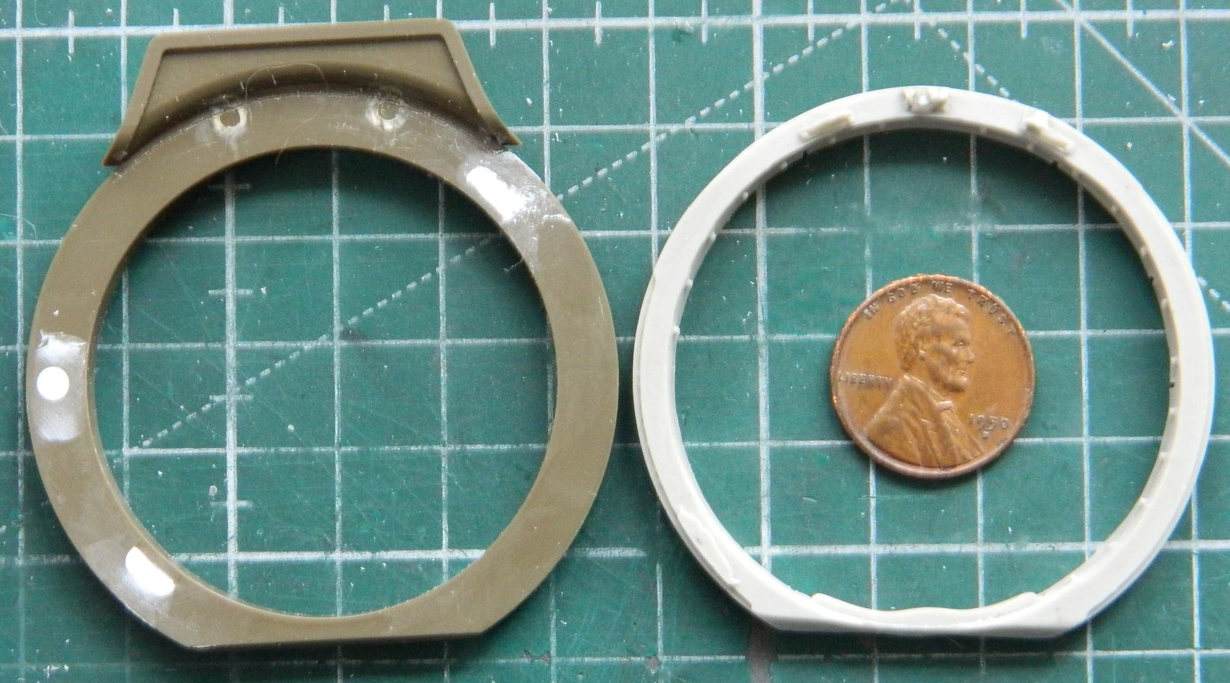
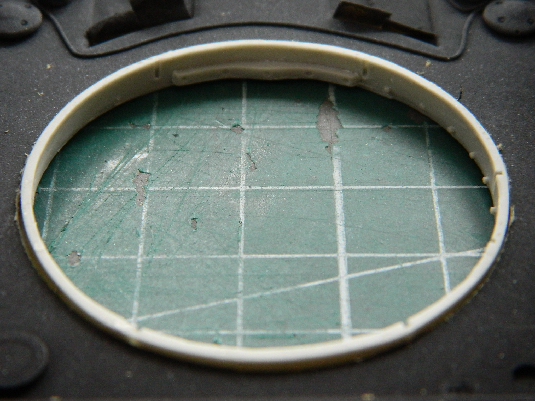
Anyone that’s been building models for any length of time knows that these things, and particularly shape and dimension, will vary depending on how any given manufacturer goes about it. And all of these things vary, even when one is working the same subject in the same scale in the same area. Whichever manufacturer’s turret was used as the starting point for the clear turret I sourced this panel from was different from Tamiya’s turret and the actual curve(s) differed, resulting in something that didn’t quite match:

The shape differed no matter which angle I looked at it from; the above photo is shows the differences (and there were a few). Having spent a few hours filing, sanding, grinding, and polishing, I was most eager to go through that process again (I hope you realize that was sarcasm), starting with the filing step. Once this had been filed so that all curves matched, sanding and polishing followed (I managed to avoid the grinding step) to restore what transparency the medium (resin) would permit:
Seeing as the remaining gaps were so small, I tried something different and used Vallejo’s Acrylic Resin Plastic Putty #70.401 to fill them:

I don’t intend to trash this product. There are probably those who use it and like it. Until this project, I’ve only used this putty to replicate weld beads and have liked the result. Once the putty cured overnight, I started sanding it and didn’t like how that went. The putty came up in chunks without really bonding to either the plastic or the resin. Having tried something new for me, I removed all the Vallejo putty and went back to using my preferred product for this task, 3M’s Acrylic Putty which worked as well as it always does.
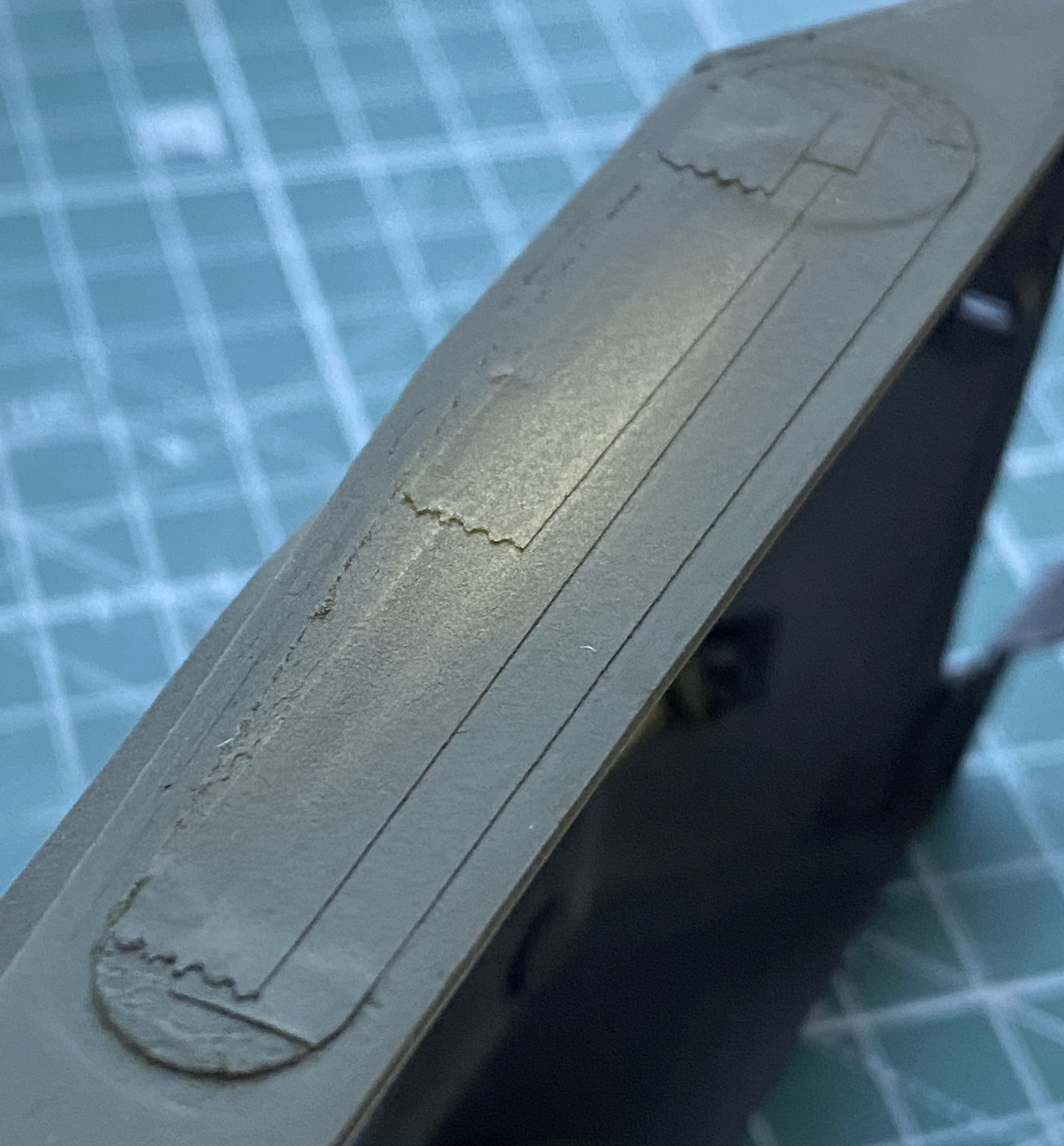
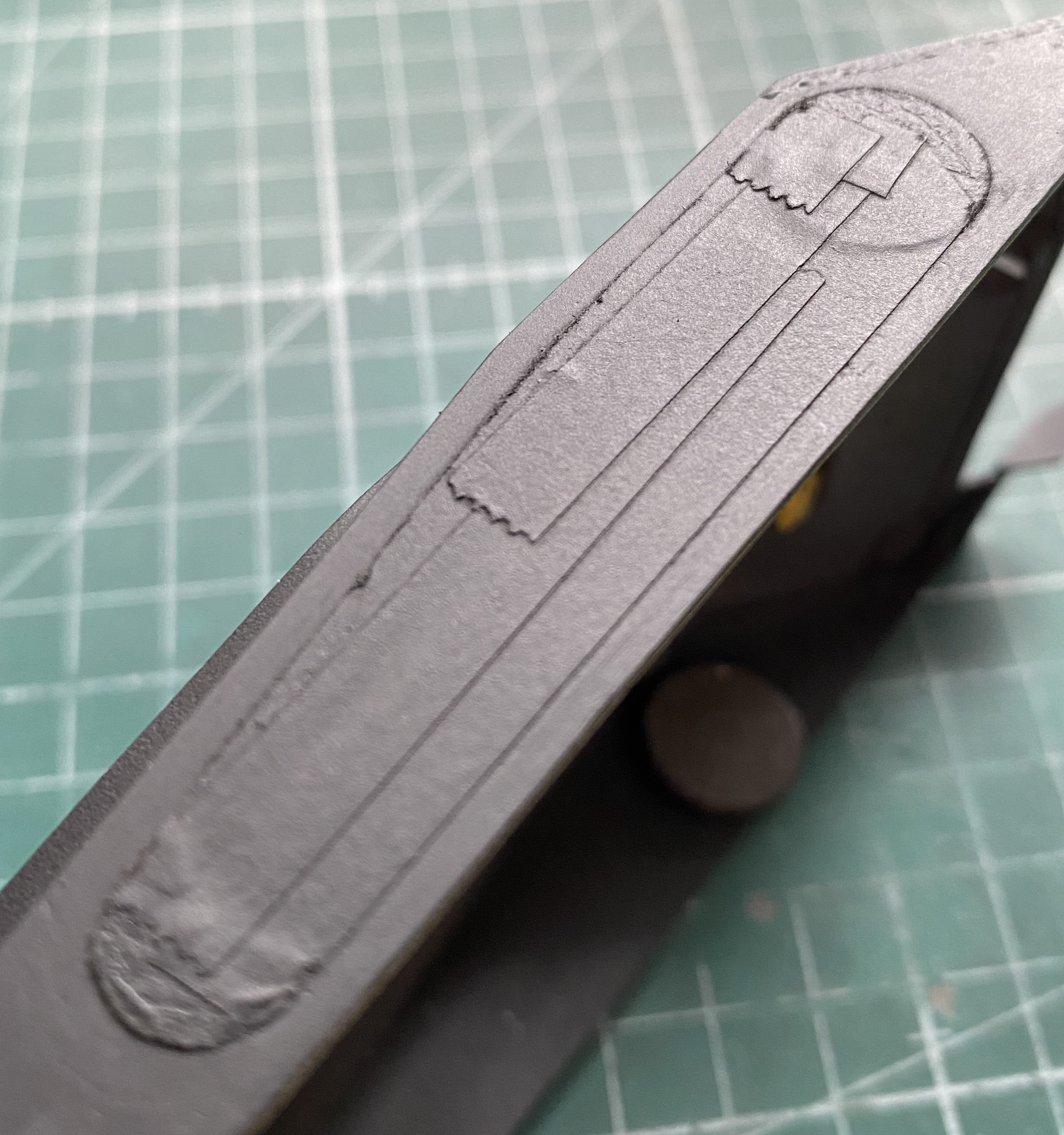
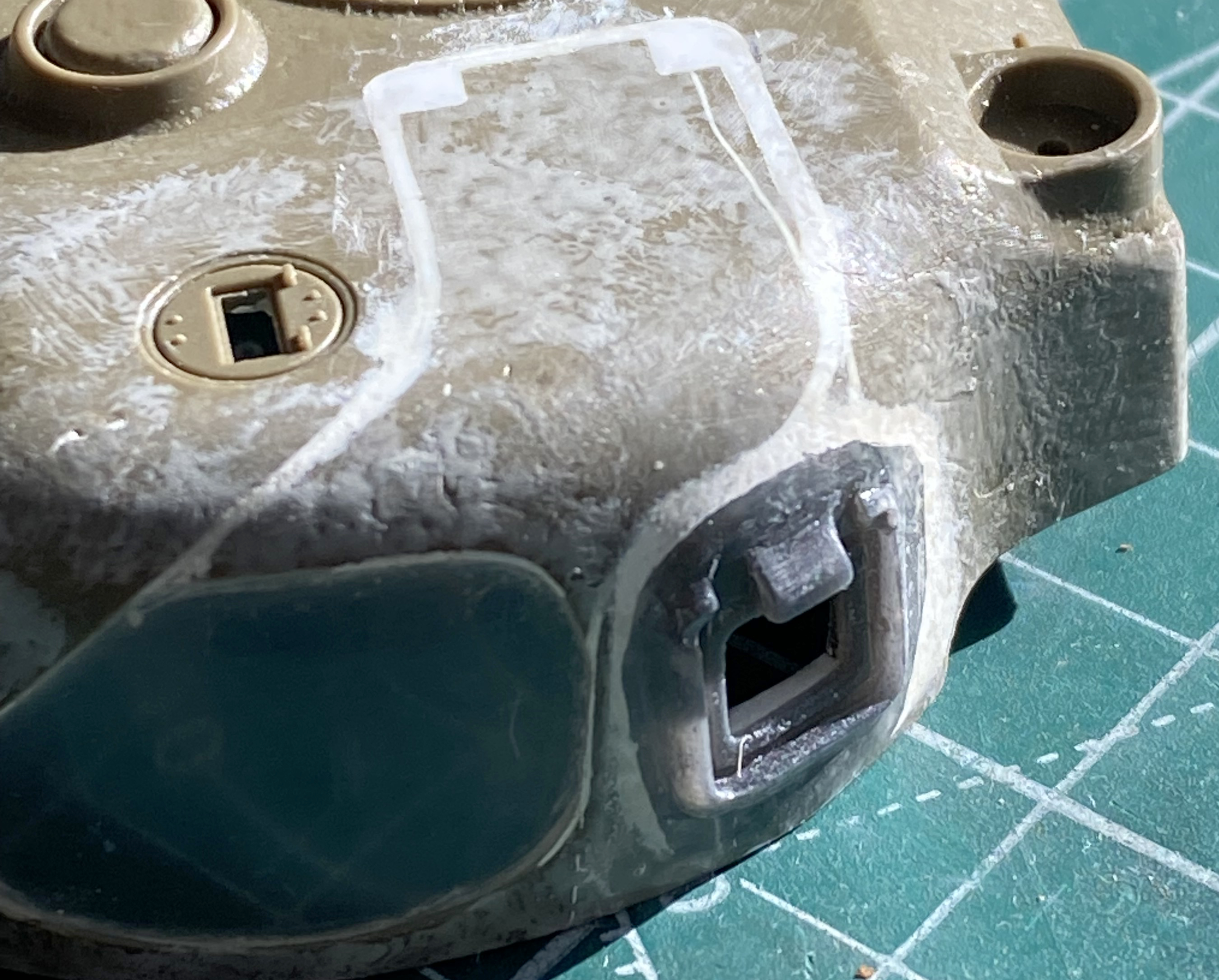
While the putty was curing, I started work on the clear panel for the hull. That started by outlining the area I wanted to excise and replace with clear styrene:

Then there were many, many, passes with a panel line scriber to dig through the plastic. I got the outline subtly off and didn’t notice that I bobbled the lower left where the curve meets the lower line (because caffeine levels in the bloodstream vary over the course of a day). I cut the error square (ish), inserted scrap styrene, and reworked the curve while cleaning up the jagged edge left by the scriber. The upper hull was dry-fitted to see if I had achieved what I was trying for:


[It’s at this point that we’re having a quiz. I have overlooked something that I didn’t notice until later in the month. The question to you is, have you figured out what I overlooked? The answer will be revealed at the point in the build where it finally dawned on me.]
With the opening defined, it was time to cut a piece of 0.015″ (.381mm) clear styrene to fill it:


Rather than attempt a rather long butt joint by cutting the clear insert to the dimension and shape of the hole, I decided to carve a depression of about 1/8″ (.0625″ or just under .2mm) wide for the styrene to settle into:

As you may have noticed in the above photo, what is the bottom of the hull’s side is a long and narrow strip of plastic. The line that crosses it perpendicularly is where it snapped. Significant pressure is required to scrape away the plastic and you can see that I didn’t get very far along before it snapped. I knew there were fairly large gaps where the sponsons met the upper hull so I had the room to use 0.010″ (.254mm) styrene to back the long and narrow strip. Even with the backing, because plastic is flexible, the break kept opening. I widened the gap of the break and inserted a scrap of 0.010″ (.254mm) to provide strength to the repair. It worked because during the rest of the excision, it didn’t break again.
It took some time but I finally got what I was after (I thought):

I didn’t realize before I had glued the clear panel in place (probably a drop in caffeine levels) that the depression I’d scraped into the plastic wasn’t quite uniform in depth. (If I ever do something like this again, I will jig a tool that will show me when I have reached the intended depth.) By the time I came to that realization I had already glued the clear in quite firmly and didn’t want to even try to remove it. Lesson learned, continue on.
I was most careful with the glue (Tamiya’s Super Thin). I got almost all the way around the periphery with the gluing process before an errant nerve pulse (twitch) caused my ancient hand to bobble the glue. In the following photo you can see where that happened at the bottom right of the clear panel:
Not optimal but by this point, the process of this built has increased my depth of experience with getting something that isn’t clear to become clear.
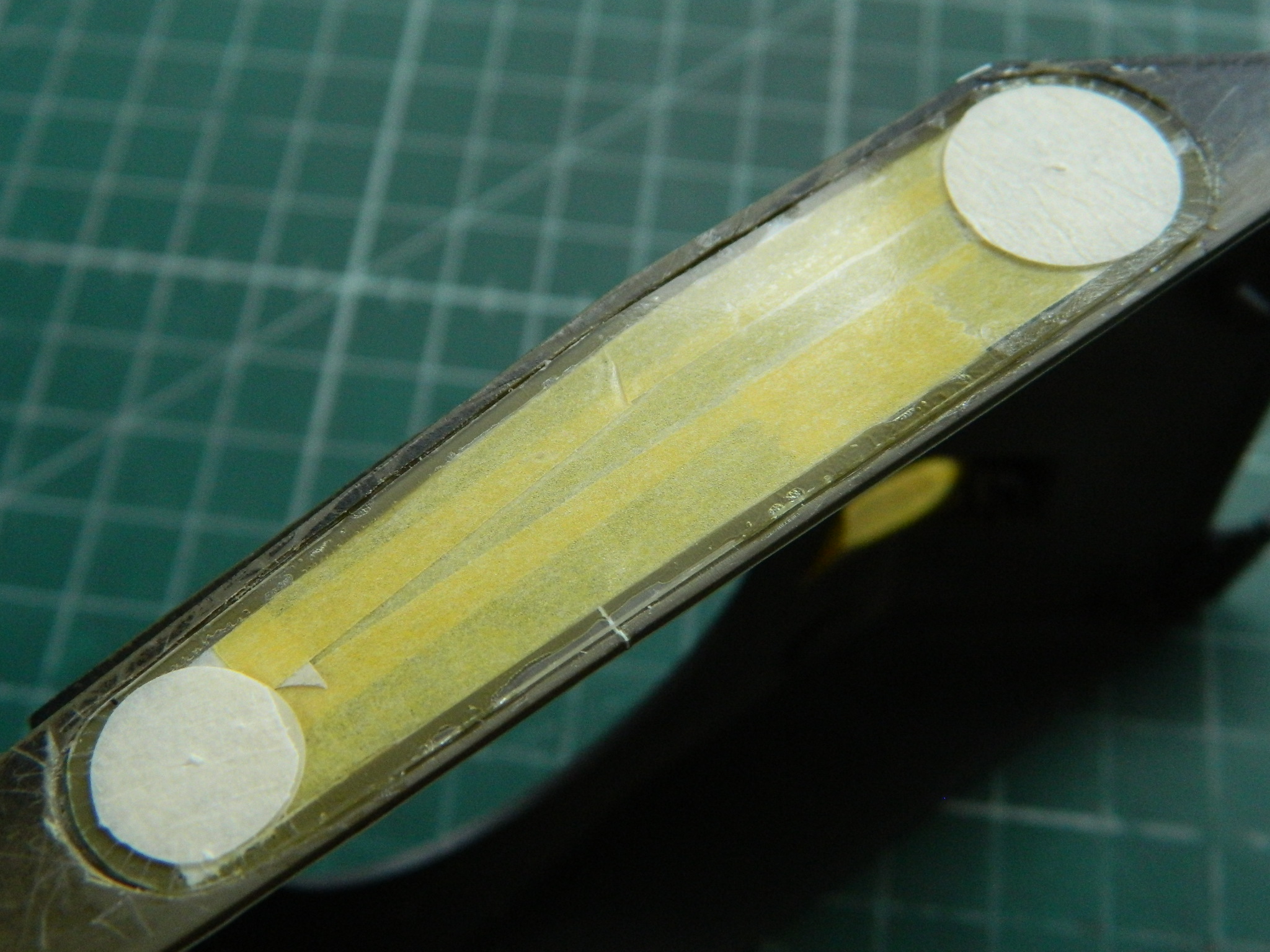
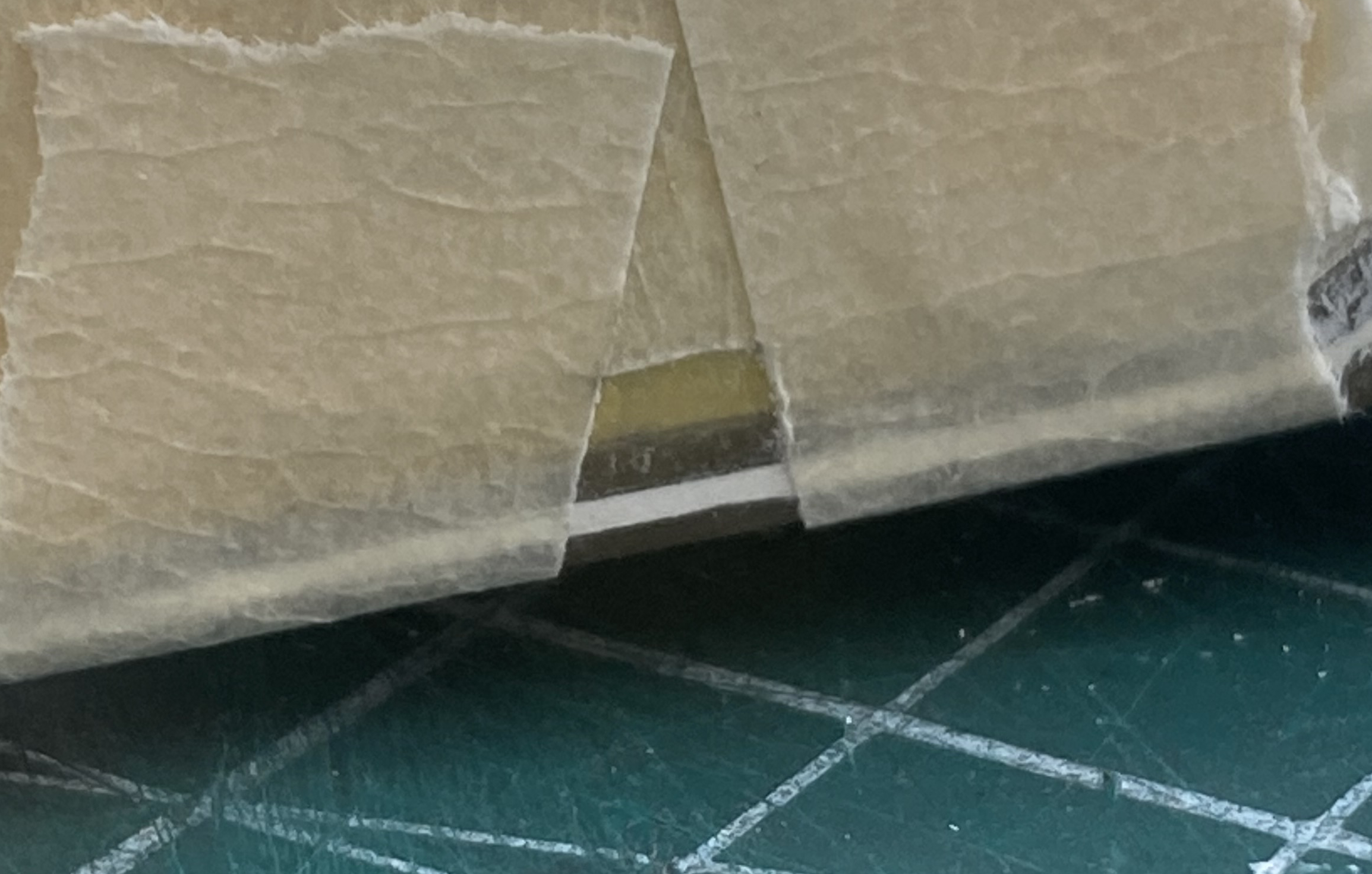
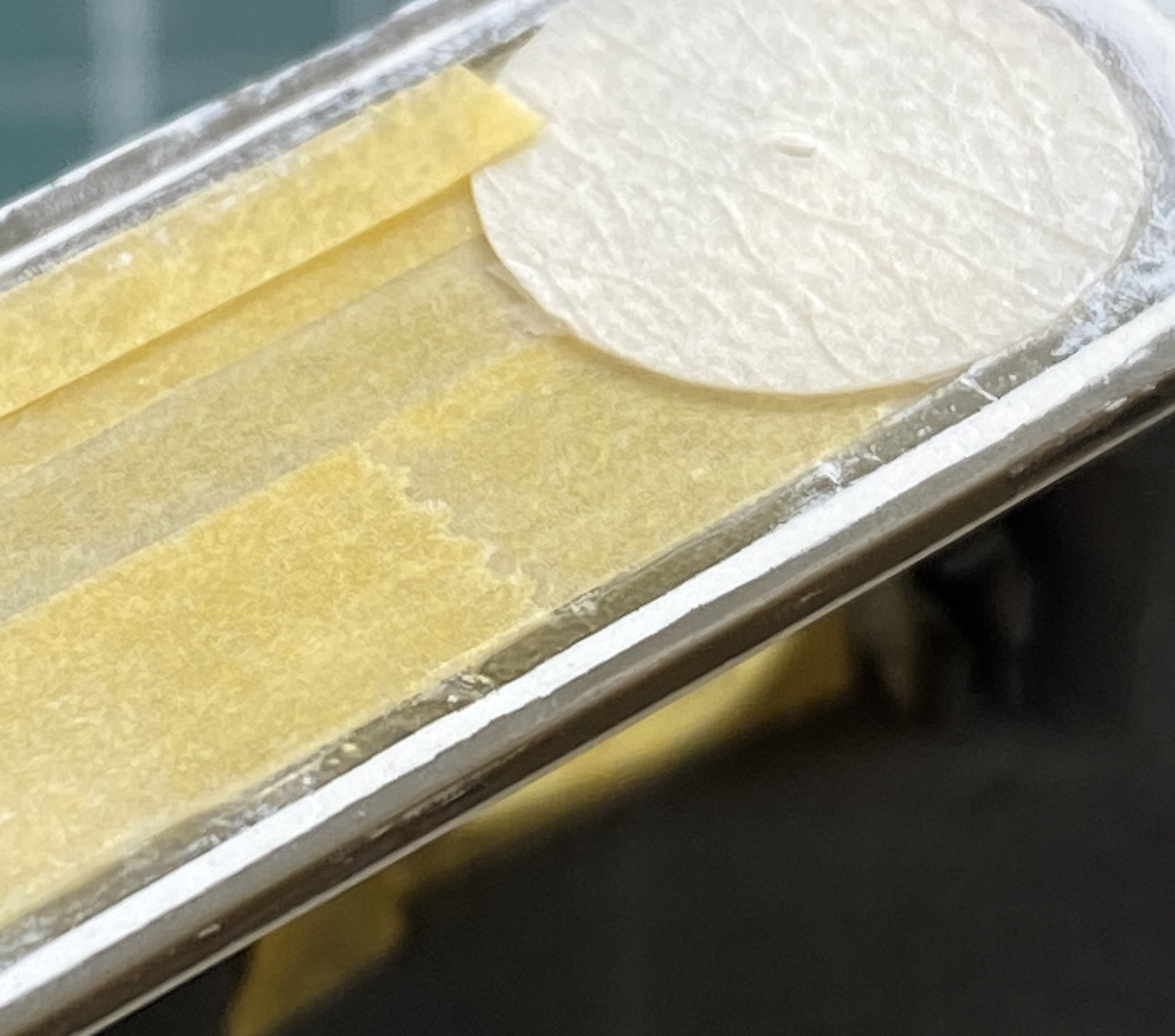
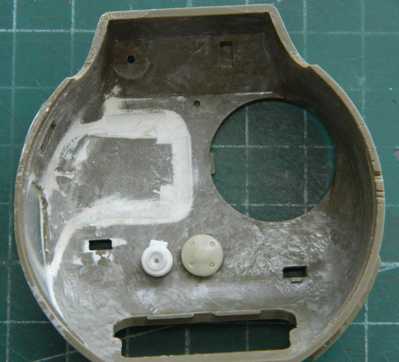
With a lot of puttying and sanding pending, I wanted to mask the sections I want to stay clear. Since I will also need to mask the inside (because, painting, y’know), I started there. It will make aligning the masked-off area match on both sides easier to start inside the hull and match that from the outside:
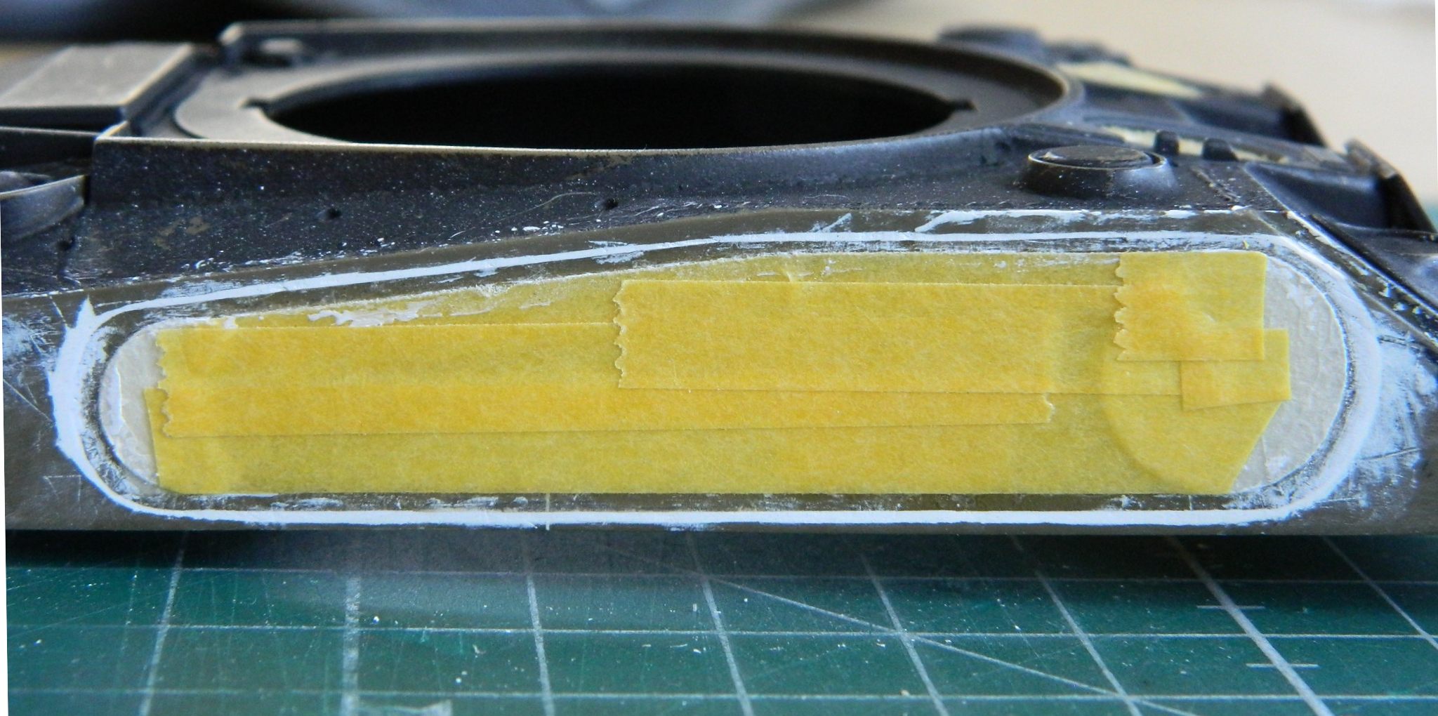
Then mask the outside to match:
“Insanity can be defined as doing the same thing over and over while expecting different results each time.” Yeah. That would be (and frequently is) me. Don’t ask me why because I have no answer that makes sense (even to me), but I tried using Vallejo’s putty again:

Probably surprising only me, it worked as well as it didn’t on the turret. ::face palm:: Fine. Got the hint. I removed all the Vallejo putty and replaced it with the 3M putty.
Since the driver of this build is to attach the upper hull, I added the screen to the rear of the engine compartment while I was waiting for the (CORRECT) putty to cure:


Time to address the glue bobble. I masked it off from the surrounding plastic:
I started sanding out the glue splotch with 320 grit, then went through the grits of 400, 600, 1200, and 2000 and finished off with Novus #2 Plastic Polish. If one knows where to look (and looks very closely) there is a very slight haze at the repair site. I will be surprised if anyone ever notices it:
With the putty cured, the area was masked again and it was filed and sanded:
I forget what I was painting (this from the person who can get up to go get something and forget what he got up for before leaving the room he’s in) but I had OD Green in the airbrush cup. I decided to use that as a primer to see how well I did blending the putty between two surfaces. My efforts can be summed up in one word.
Inadequately:
Time for more putty, more drying time:

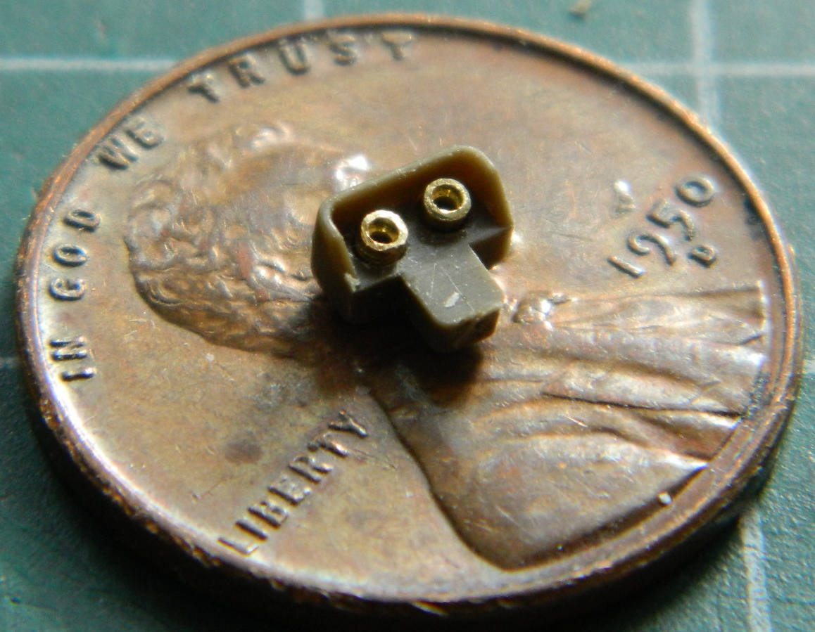
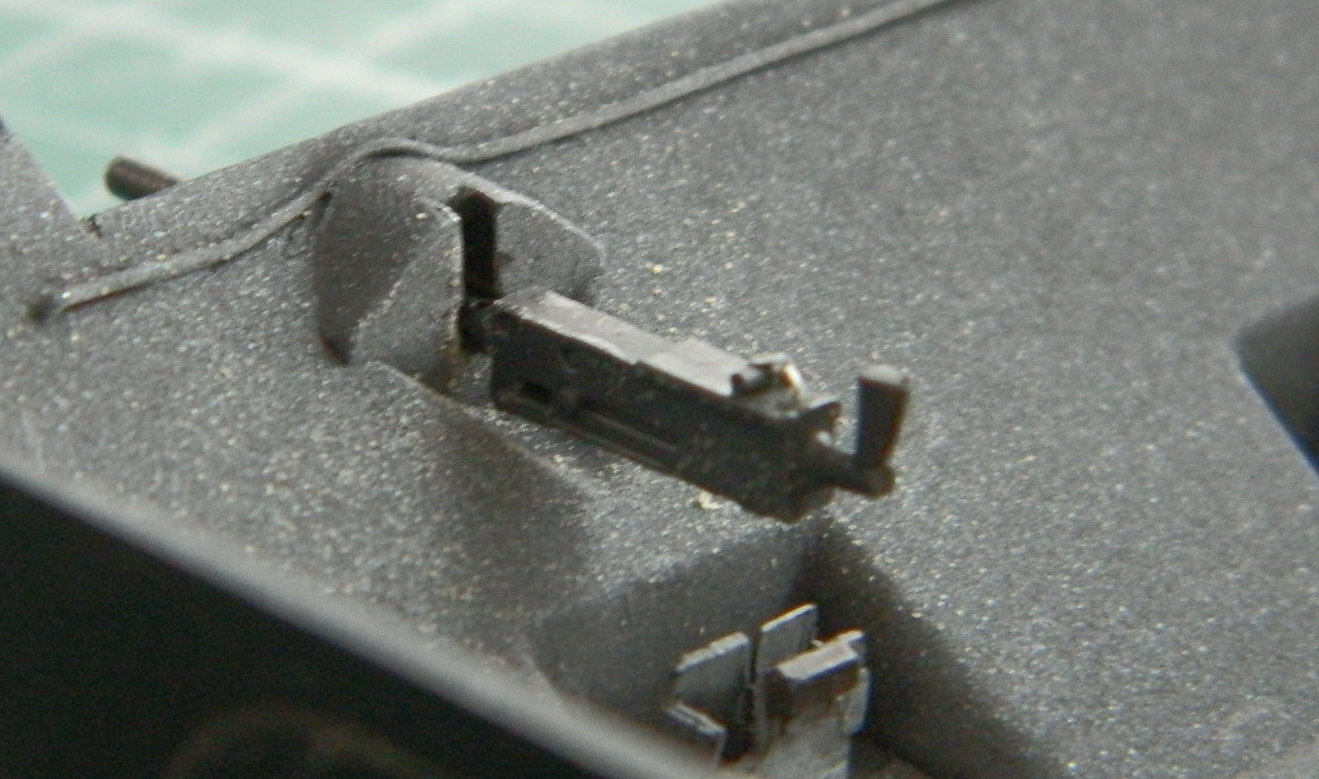
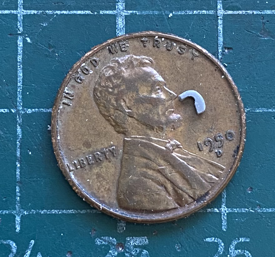
While the putty was curing, I added Grandt Line bolts and the locking pins to the gas cap covers:

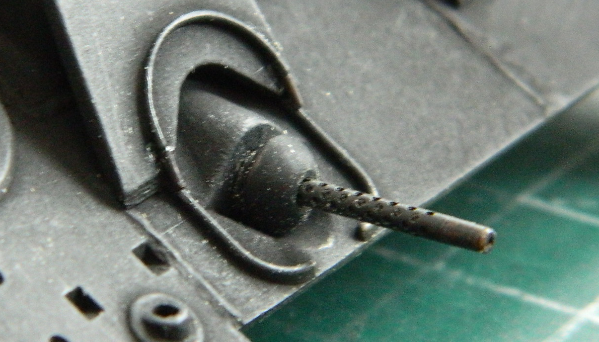
I also checked the exhaust tips of the auxiliary generator. The kit molded them as solid stubs. I found a piece of .020″ (.508mm) copper tubing that the Eyecrometer said would work, drilled out each end of the tubing to a more scale thickness, and then cut off each end of the tube. They were aligned and glued in place:
With the putty completely cured, this time there was more filing than sanding. Files have flat surfaces so I decided to use that property. And since I had pretty much bollixed up much of the added weld seam of the glacis, I replaced that as well:

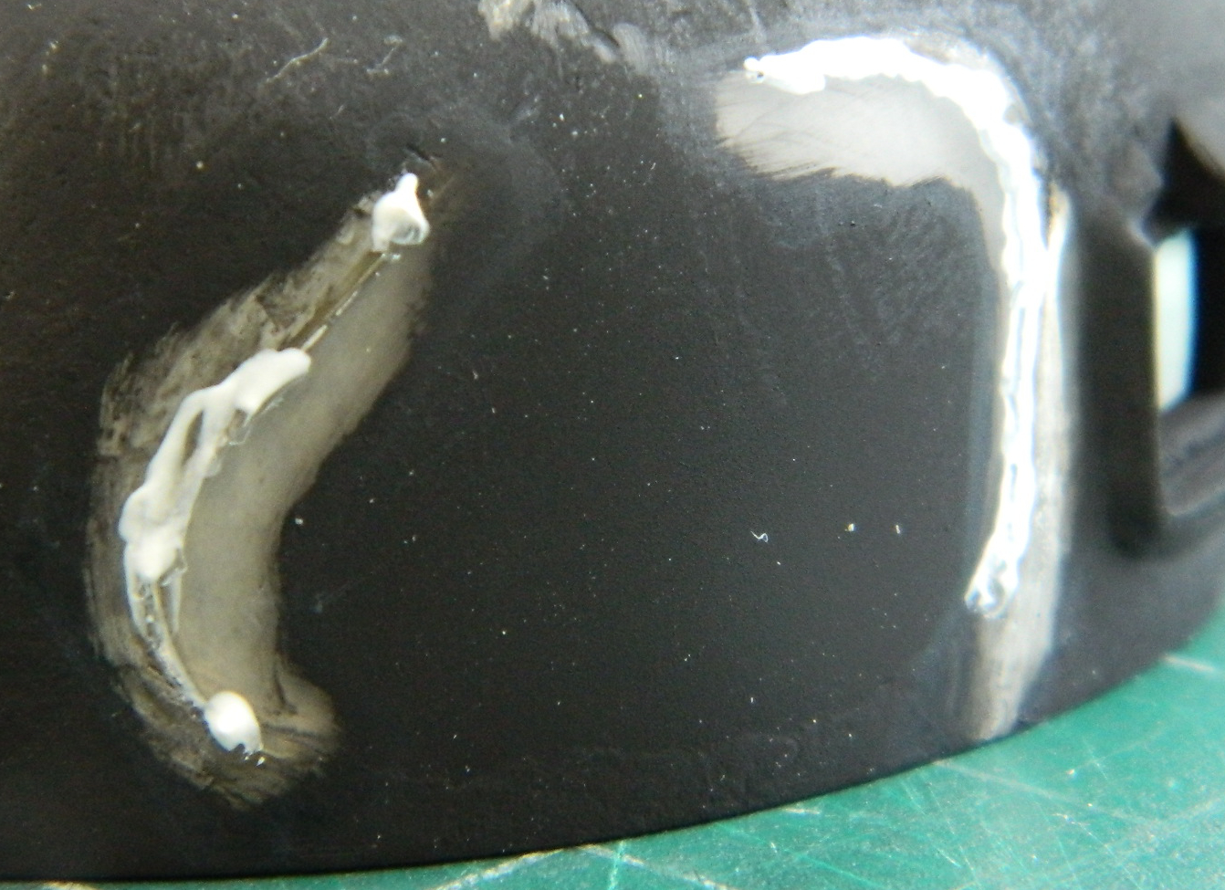
This time I had flat black in the airbrush cup so I primed the hull side again and this is when I (finally) realized that the depression I’d scraped into the side was of inconsistent depth. A wee bit of jiggery-pokery (evident at the left side of the clear panel) was required to get things to look like they were properly fit:
Close enough.
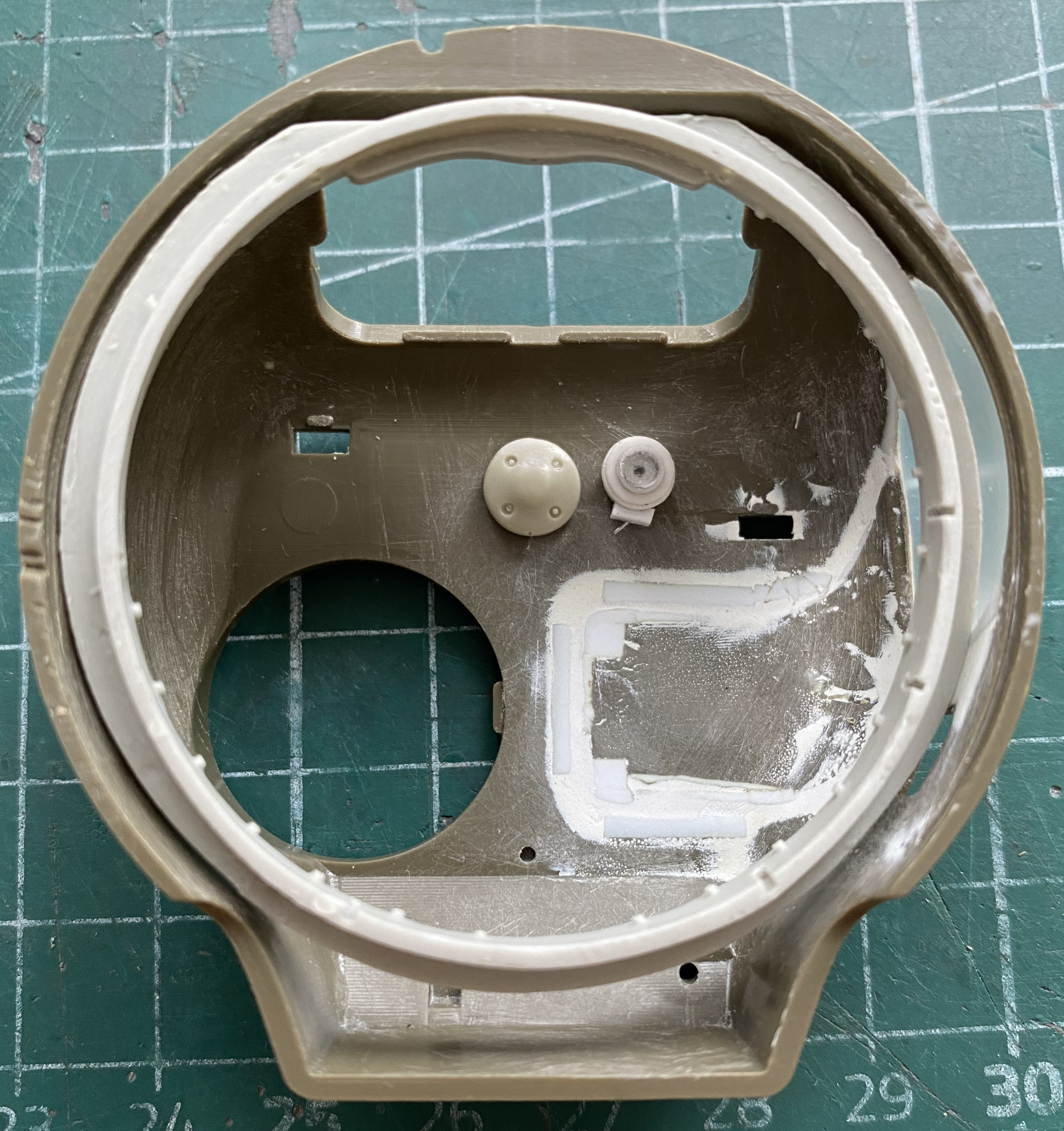
There are actually lights inside a Sherman so that the crew can see what they’re about with the hatches closed. The later lights have a changeable filter between clear and red (the latter to keep dark-adapted eyes dark-adapted), the early lights only have the clear. I decided that the demands of the day probably precluded mechanics from upgrading bits that weren’t essential…such as interior lights. I found a reference photo that I could pull dimensions from and scratch-built one:
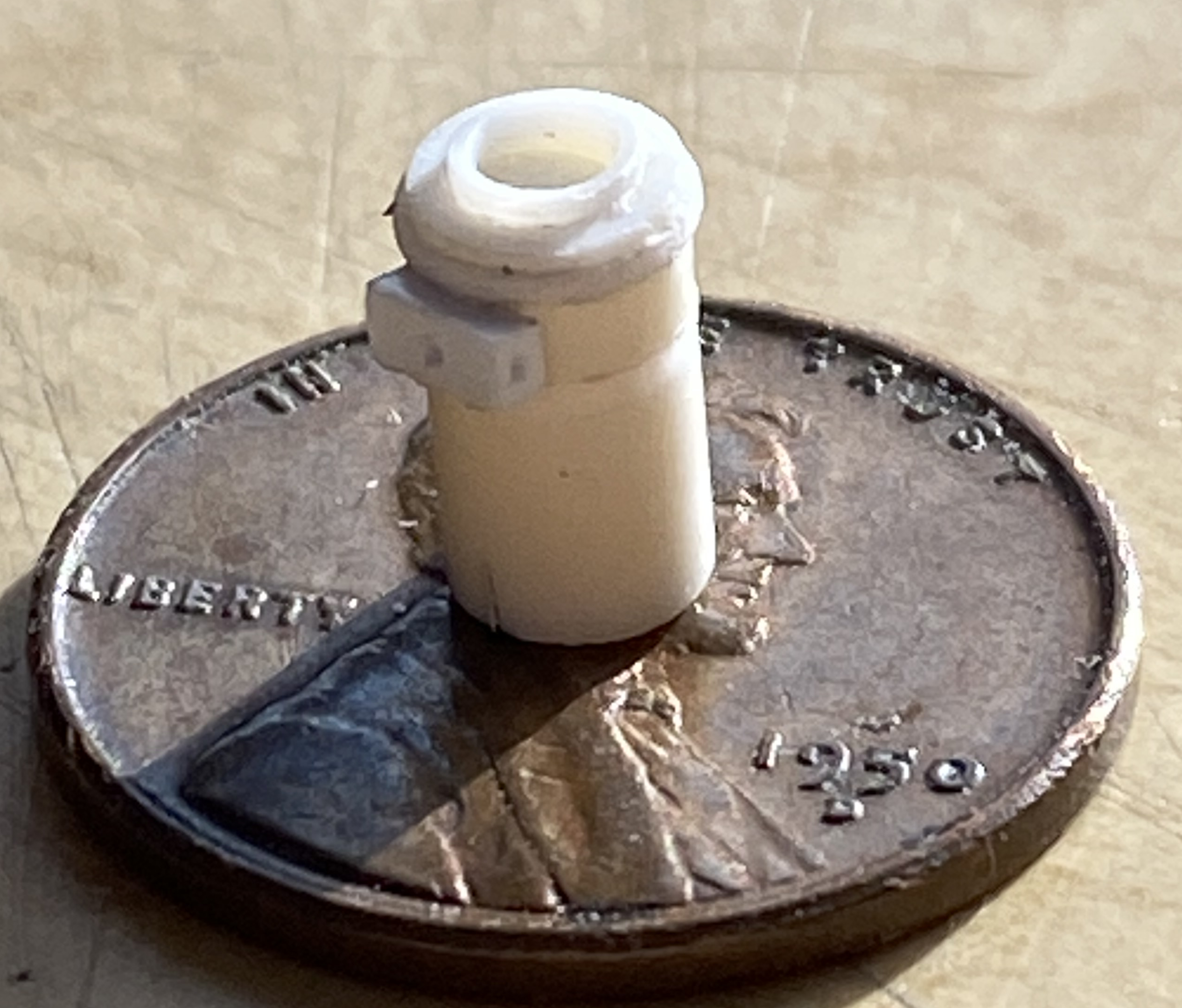
I can scratch-build one. I can scratch-build multiple copies. I just cannot seem to build the copies as easily (or as well) as I could the first one. So the one in the photo above is the first one…and I used silicone molding putty to make copies of this one. This is what I used and it’s available from Michael’s (at least in the US):
Mix equal weights of A and B, WORK QUICKLY because this stuff sets up quickly, and in 15 minutes there’s a mold. Since I need three lights, I made three molds and filled them with resin:

I wasn’t thrilled with how the casting on the left in the above photo turned out so I didn’t use it, I used the master instead. The pour stubs were cut off and 0.010″ (.254mm) solder used as toggle switches:
Time to add them to the crew compartment in front (two of them) and the turret roof (one, obviously). Of course I wanted to put them in the correct places, so I spent a couple of fruitless hours online looking for a photo of where they should go. Fine. I’ll guesstimate and put them where I would want them (and it wasn’t until I had the upper hull WAY past the point of removal before I found a photo…because I was looking for something else, of course…showing where they went) (I like where I have ’em better):
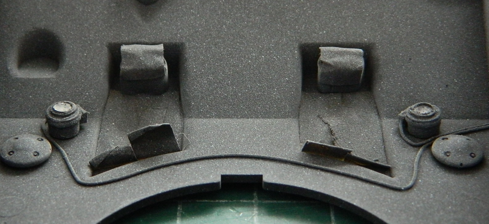
I was curious as to what the exhaust tips I made would hook up with so I dry-fit the upper hull to see what’s underneath them. As it turns out, there are two Mystery Objects molded onto the bulkhead directly underneath the exhaust tips’ location. So once again I guesstimated that these Mystery Objects were part of the exhaust pipes and added 0.20″ (.508mm) solder to represent them:

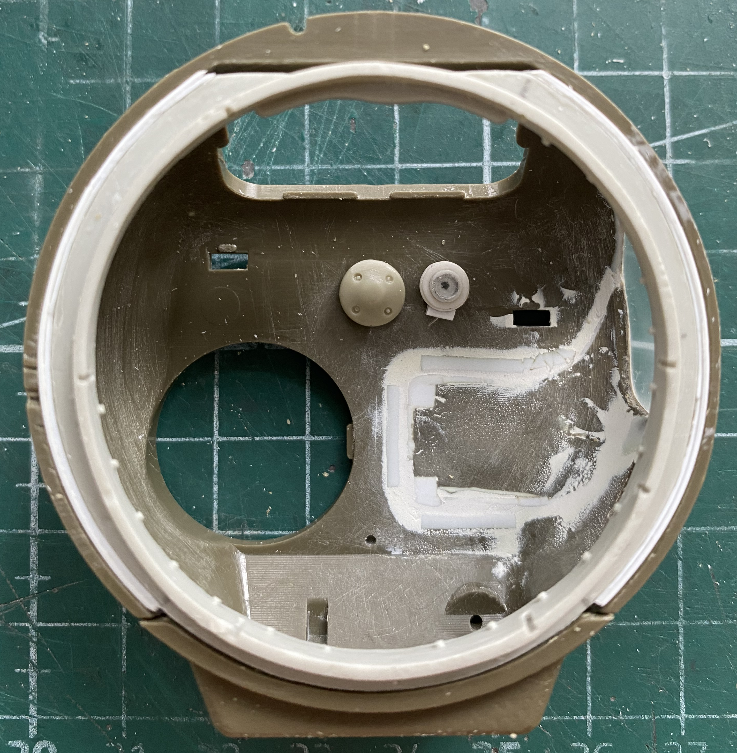
It was shortly after I redid the interior paint (flat black with flat white misted over it) that I found the correct location of these lights. Having decided to leave them, once the paint was redone I used a toothpick I’d carved a chisel tip onto to scrape away the paint on the area I want clear (it’s just easier than trying to mask something so small…I do the same thing with landing lights and periscopes):
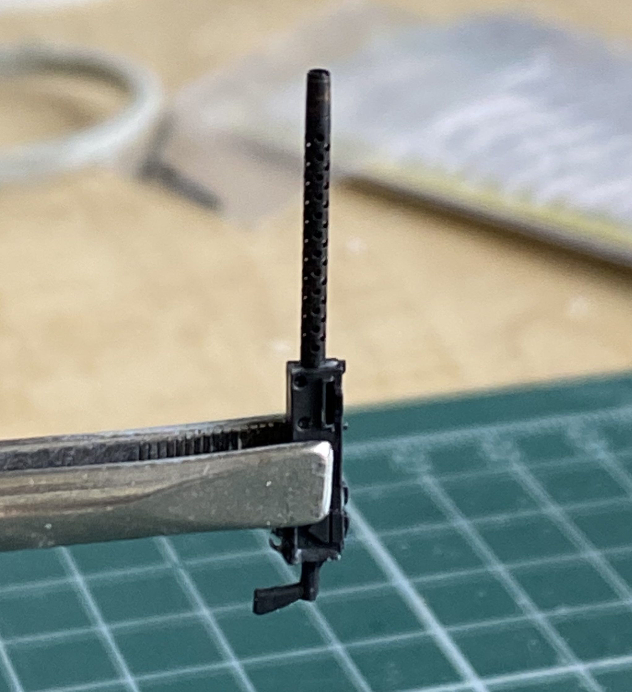
Adding the .30 caliber (7.62mm) machine gun will be much easier with the upper hull unattached. I painted the receiver my custom gunmetal (Tamiya X-18 Semi-Gloss Black 5 parts, XF-20 Medium Gray 4 parts) and added the Master GM-35-004 Brass Machine Gun Barrels that I colored using Birchwood Casey Brass Black Metal Finish (BRILLIANT stuff, that):
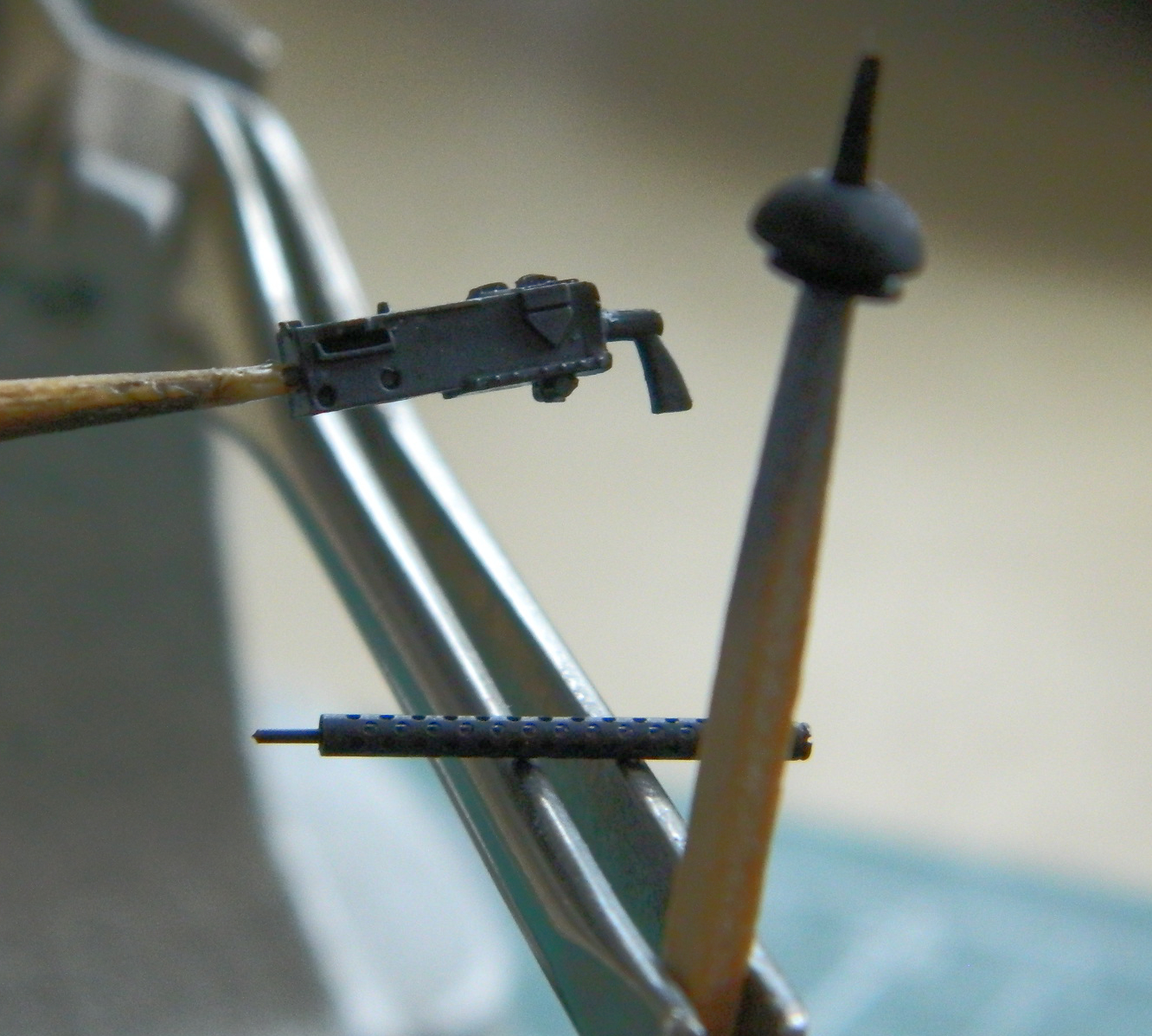
Then it was assembled:

No point in detailing the receiver because where it’s located the details won’t be seen.
With the upper hull still free, it was time to fit the turret to it. I’d checked the parts earlier and knew that they would need work to fit. These are the parts that have to play nice with each other:
They also have to play nice with other parts, as in, fit:
I can make that happen:
Often:


I also need to graft the bustle bottom to this part. It starts with tracing where I need to make the cut:

Then doing the fitting:
Fiddly but doable:

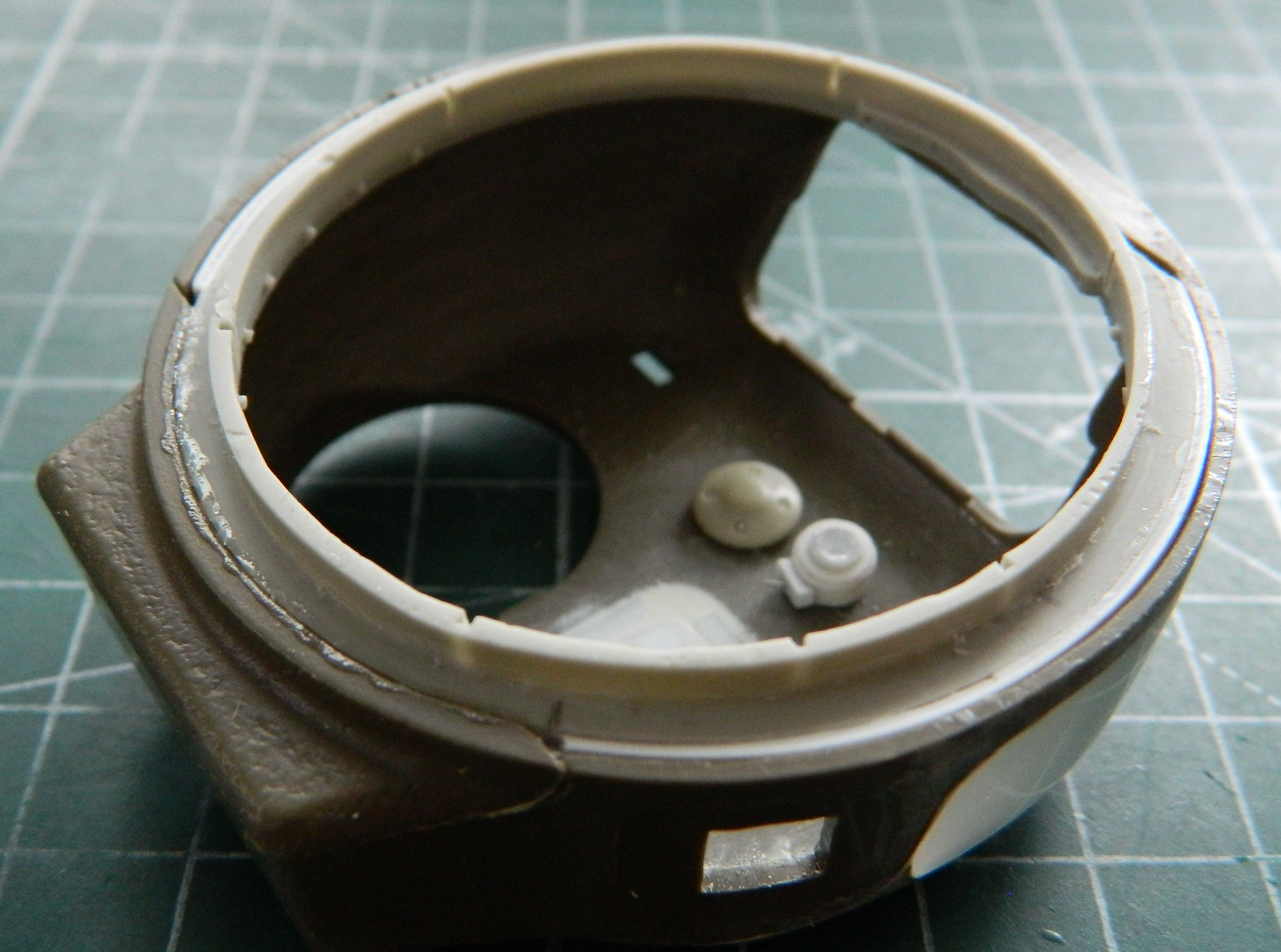
Tamiya used to mold the pistol port as an applique without the option to be opened. When I did the M4A3, I used silicone molding putty to copy the detail of the opening from a Dragon turret I have in my spare parts inventory. This enabled me to open Tamiya’s pistol ports with a bit of grafting, some putty, and cutting a hole. The resin copy was put back into the mold so that I could support it while I ground away resin to make this thinner. If I had tried to hold it in my hand to grind it, the warmth of my hands would have made the resin too flexible:
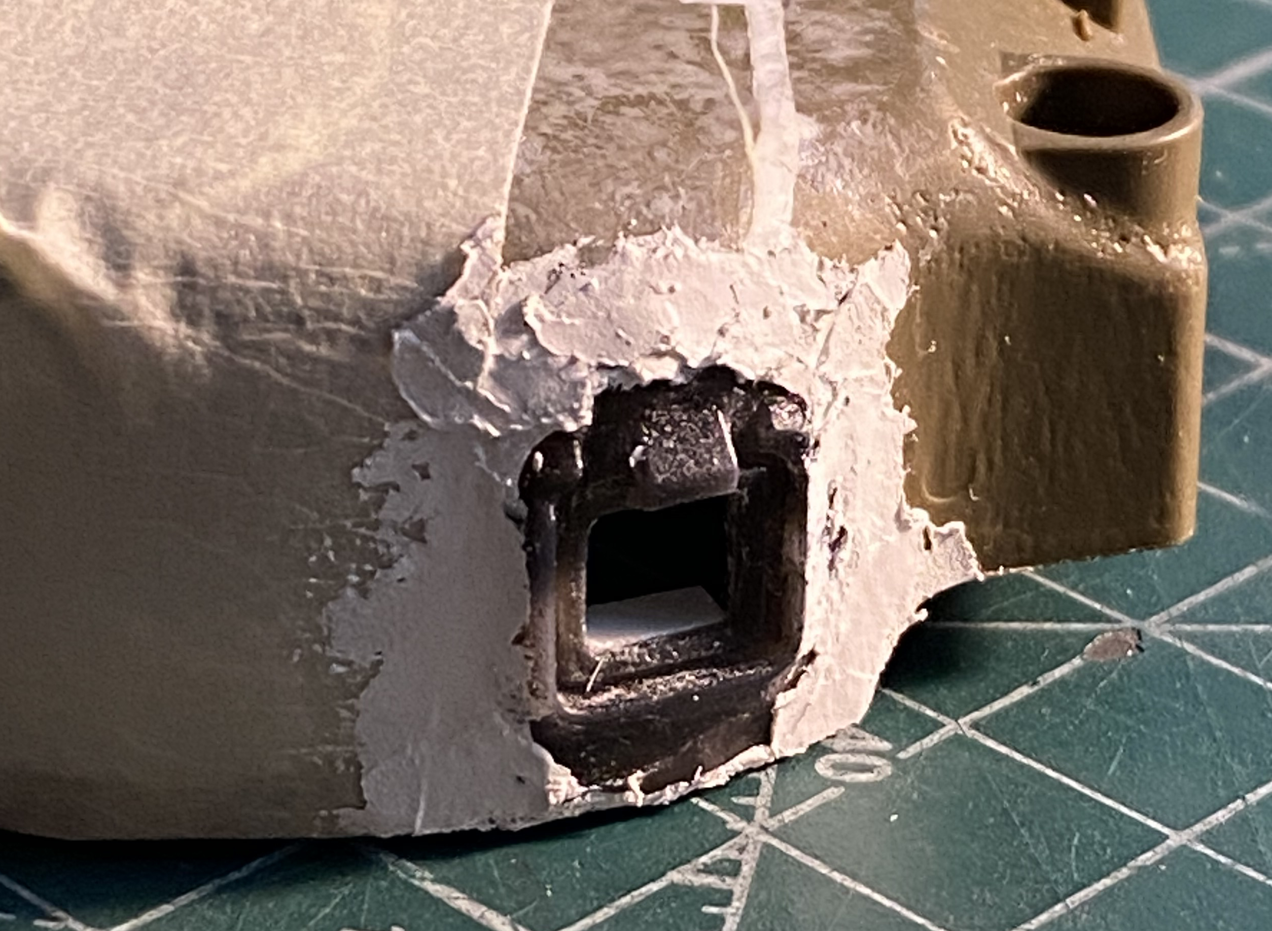
Once it was glued into place (but before the putty), I discovered that I’d misaligned it. It was easier to modify the hole than to try to pry the putty up (and have the resin part even survive):

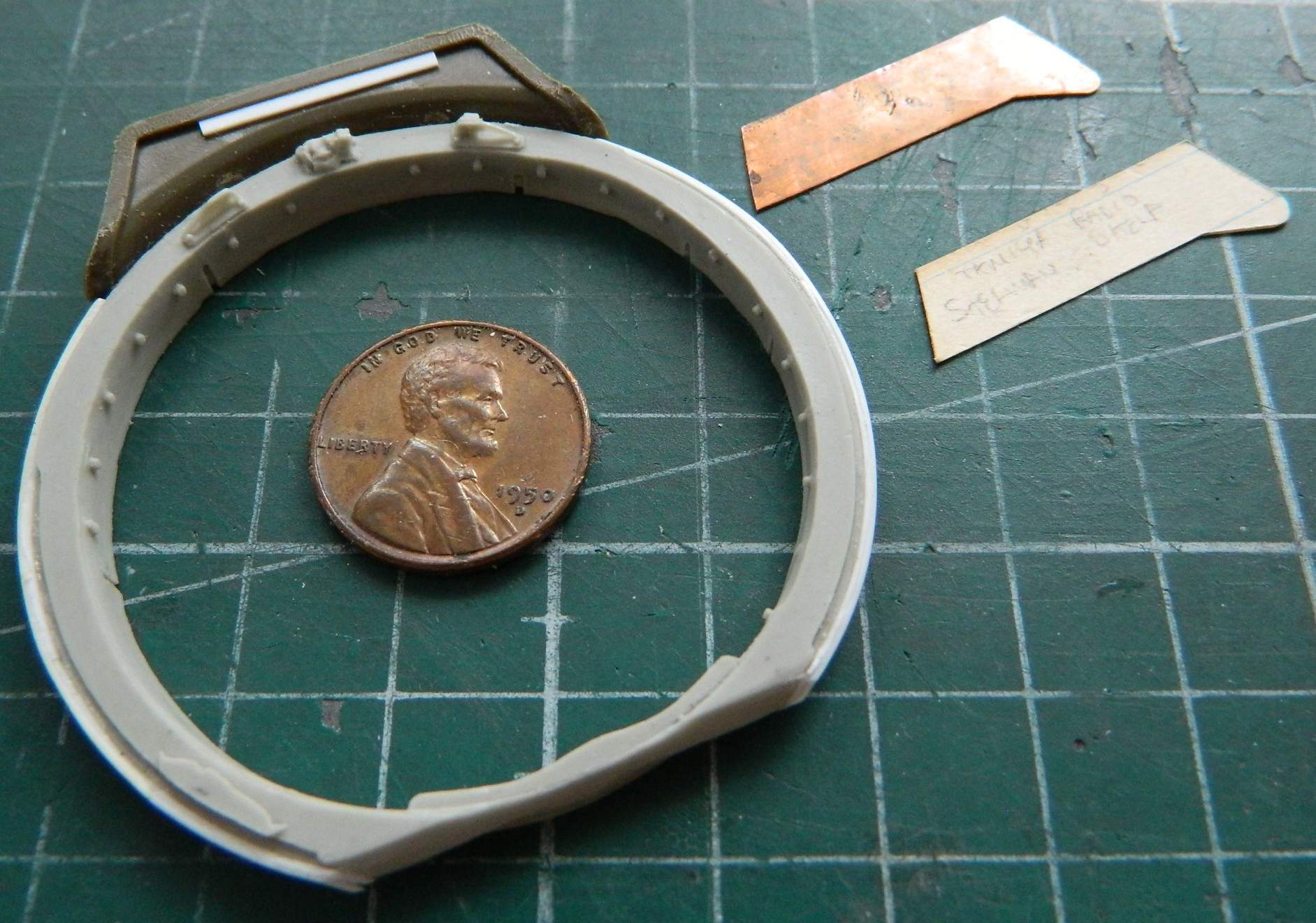
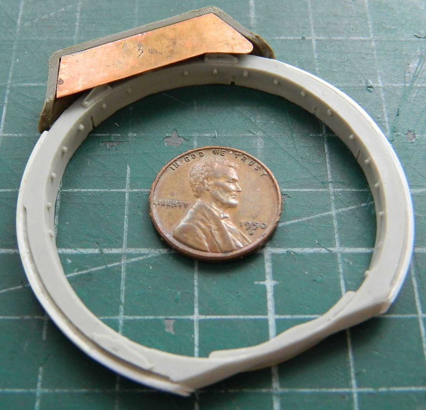
While the putty around the pistol port cured, I worked on the shelf the radio inhabits. The radio I want to use is resin, making it heavier than a plastic part is. I thought the PE shelf was too thin and that using 0.010″ (.254mm) styrene as a replacement would allow the weight of the resin to result in the shelf drooping (I assume). Instead I used the PE part to create a heavy stock paper template and then transferred that to 0.010″ (.254mm) copper shim stock. Dry-fitting showed that the shelf wouldn’t sit level, so I used a scrap of 0.010″ (.254mm) styrene to fix that:
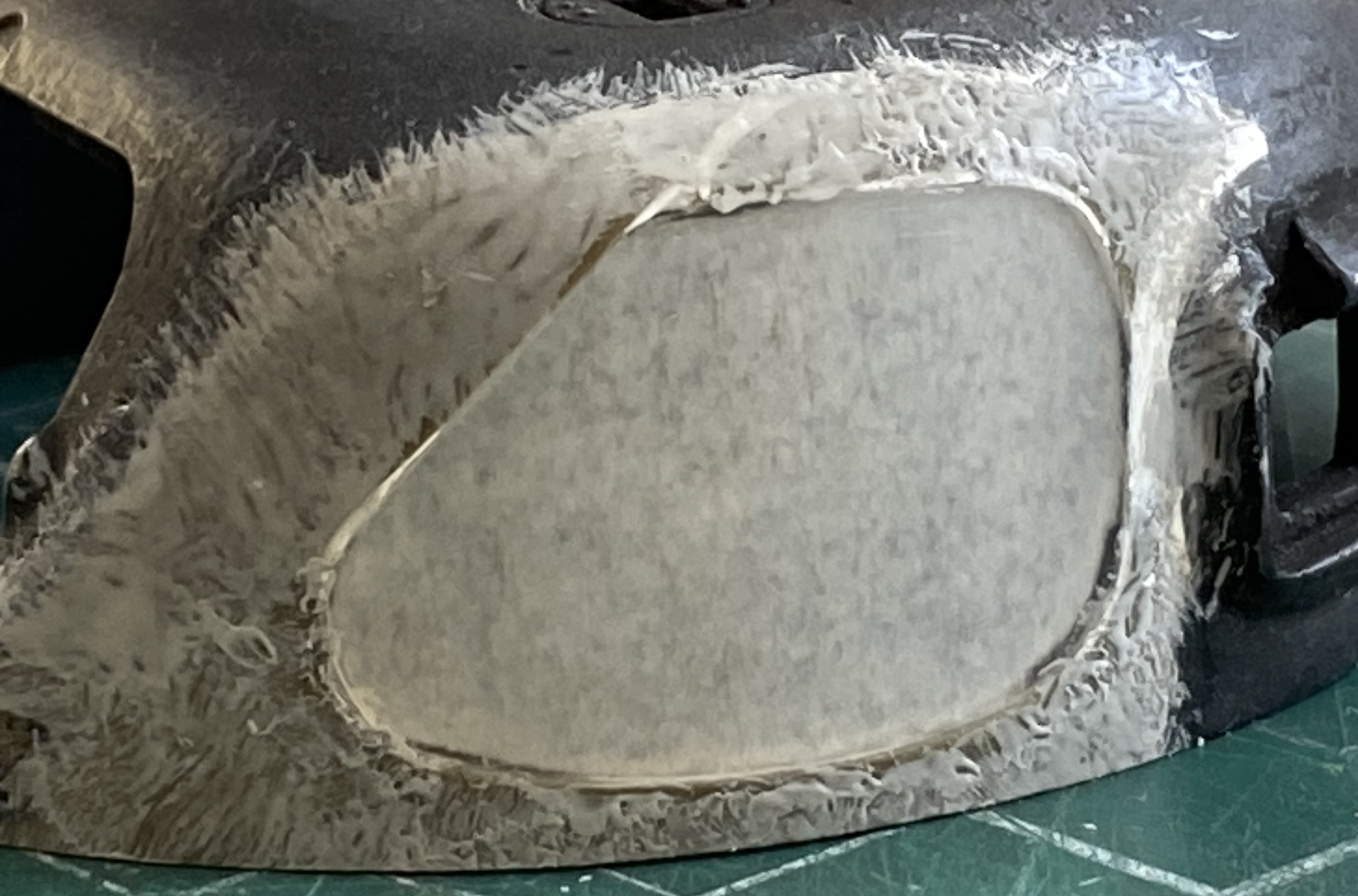
Once the resin cured, I masked over the clear panel and filed and sanded it to a precise (relatively speaking) fit:

All that sanding removed the as-cast texture which I replaced with Mr. Surfacer 500. A thin coat was put down with a disposable nylon brush and then the texture was replicated by stippling the surface with the flat tip of the brush:

And since the inside of the turret was never intended by Tamiya to be seen, it also got a Mr. Surfacer treatment:
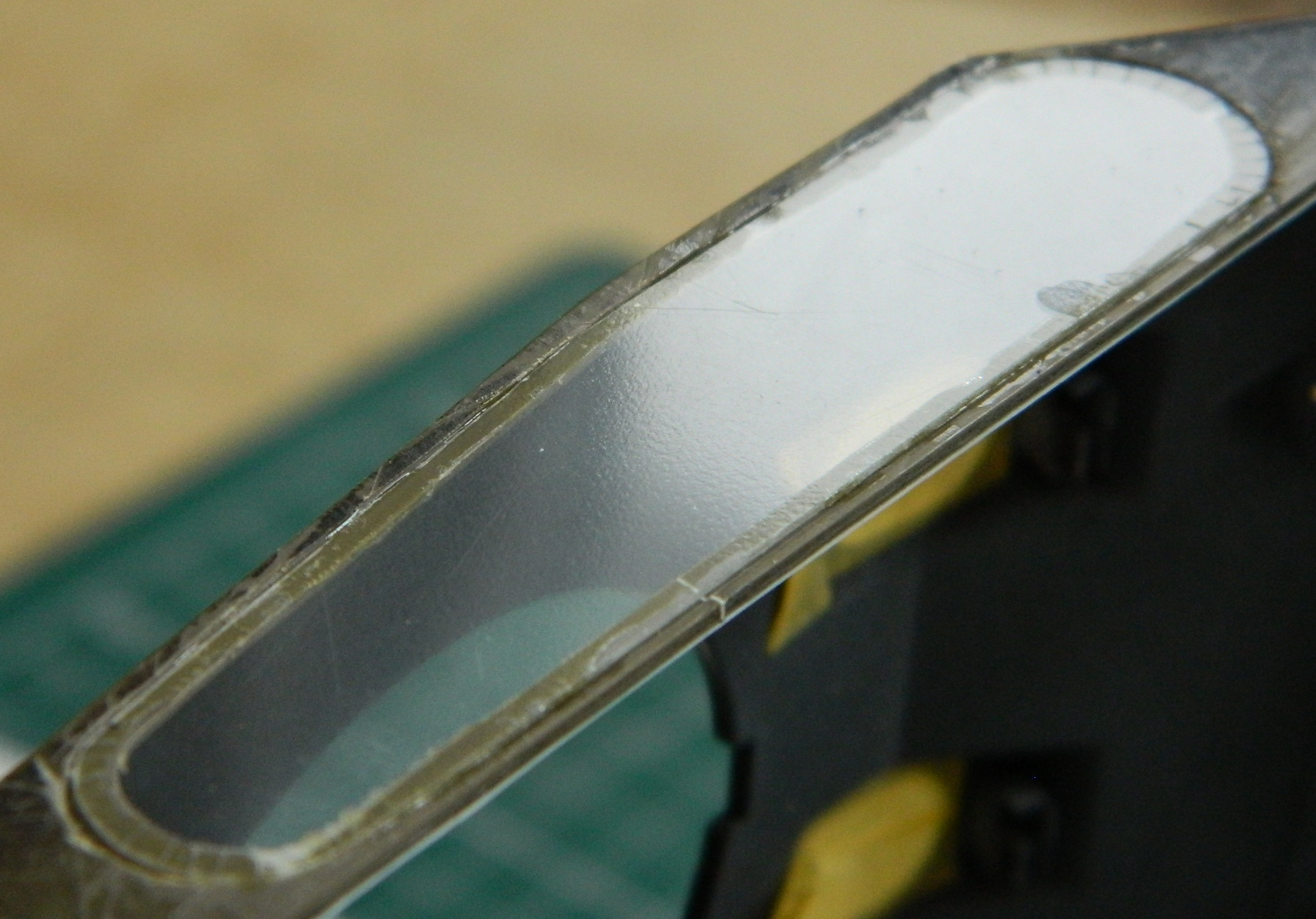
I primed the clear panel on the outside of the turret with flat black. I didn’t mask the clear because the tape doesn’t stick well to it, planning instead to remove the paint with denatured alcohol and a chisel-tipped toothpick after the OD Green is shot. The priming shows where there are still some little gaps:

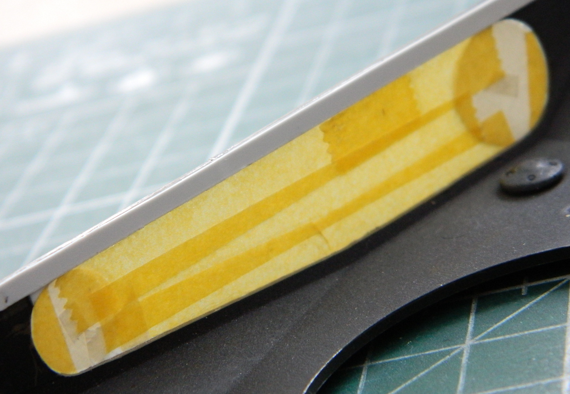
While I was here, I masked the interior of the clear part. Yes, the tape doesn’t stick very well, but it sticks well enough when tape is put in place where it will not be handled. Then denatured alcohol took off the exterior paint (easily, which is why I use it to remove paint, clean brushes, and clean the airbrush) and putty was laid down:
Mr. Surfacer replaced the texture that was sanded (and polished, of course) away:
Reapplication of primer shows that it all worked:

Before the upper hull can be attached, the .30 caliber (7.62mm) is attached:
These are about 99% of the parts that comprise the interior of the turret:
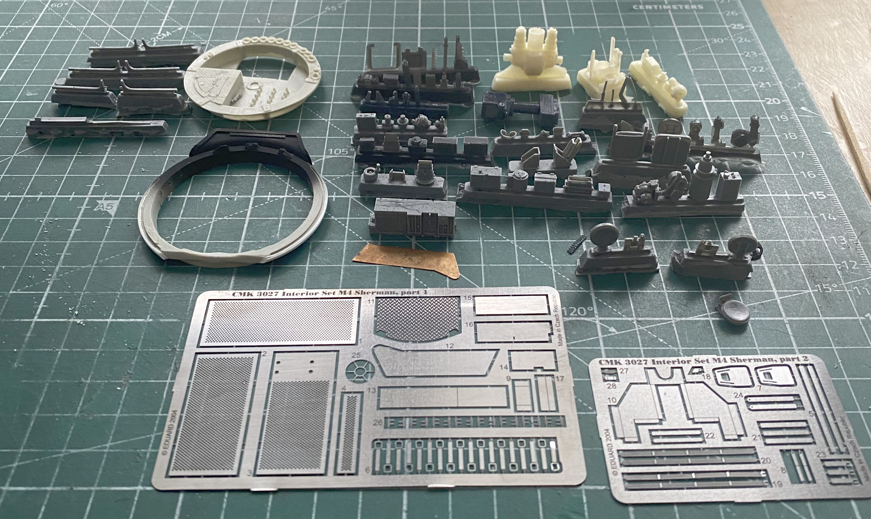
And this is what I’m replacing the kit parts with:
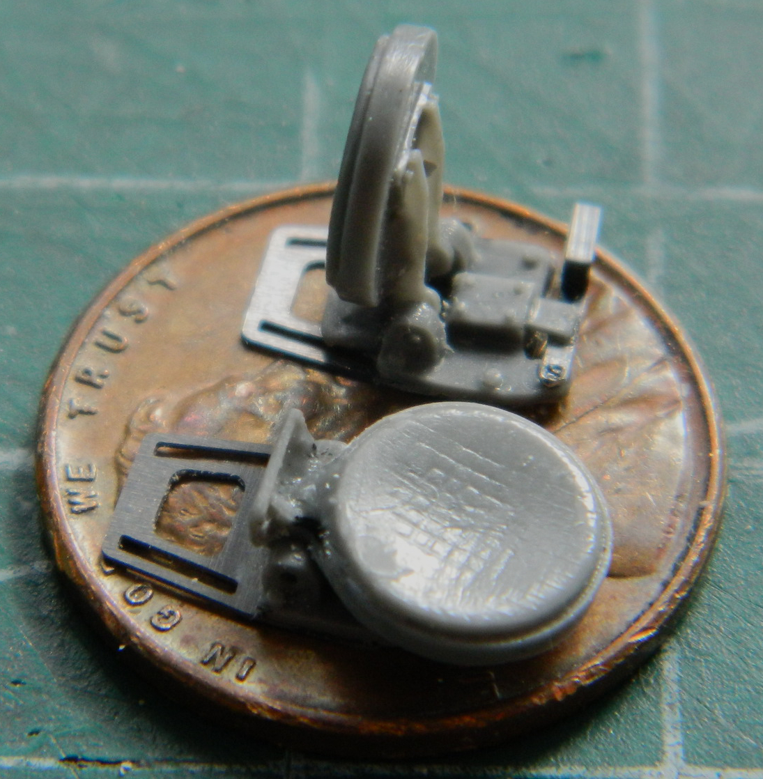
I started with the loader’s and commander’s seats. The commander’s seat is on a track that enables it to be moved up and down. Both seats also fold down (even though the directions of the AM set show them folding up) which enable the commander to have just the top of his head (at about eye level…go figure) exposed and folding down the loader’s seat gives him more room to maneuver during a fight:
The shortcomings of the Sherman’s design became evident in North Africa and emphasized during the Italian campaign. An interim measure, called “the blitz program”, was instituted to address some of these shortcomings without having to halt production to do so. This program added armor over the outside of the hull’s sides to add protection for the ammunition storage (the location of which is why a Sherman would explode and burn, not because they were gasoline powered), added armor to the turret in front of the gunner’s position, and angled plates in front of the driver and co-driver’s hatch hoods. These kits were also provided to be added at depots to upgrade tanks already deployed. Part of the blitz program was to address ill-conceived stowage of ready rounds along the periphery of the turret basket. A penetrating shot would cause the rounds to fracture, igniting the propellant, which would then lead to a catastrophic ammunition fire and explosion. The ready rounds were removed from the turret basket.
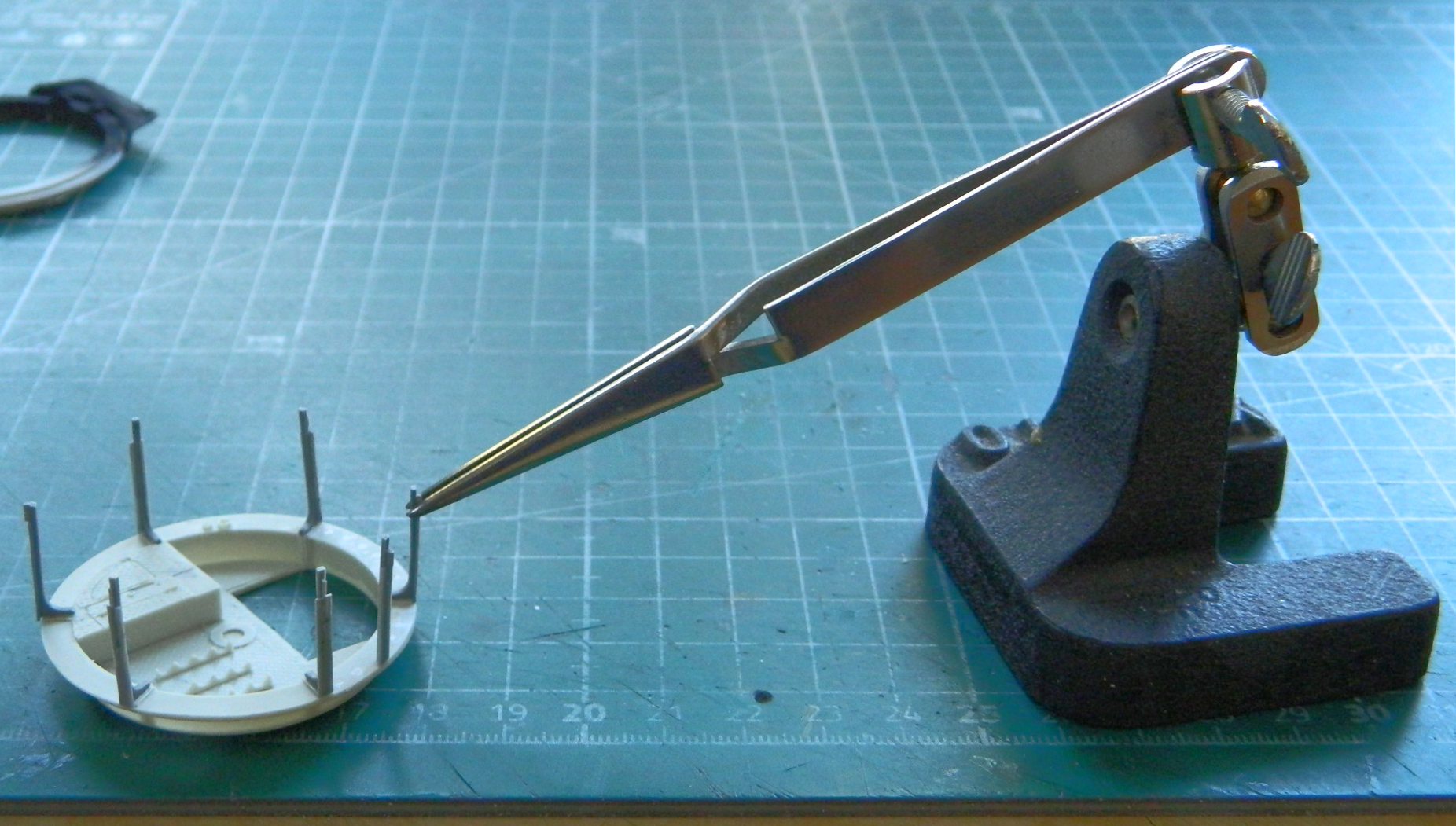
The resin AM part shows where the base of the shell would rest. Since I’m doing a “Normandy Sherman,” something that would have had the blitz upgrade, I removed those shell rests:

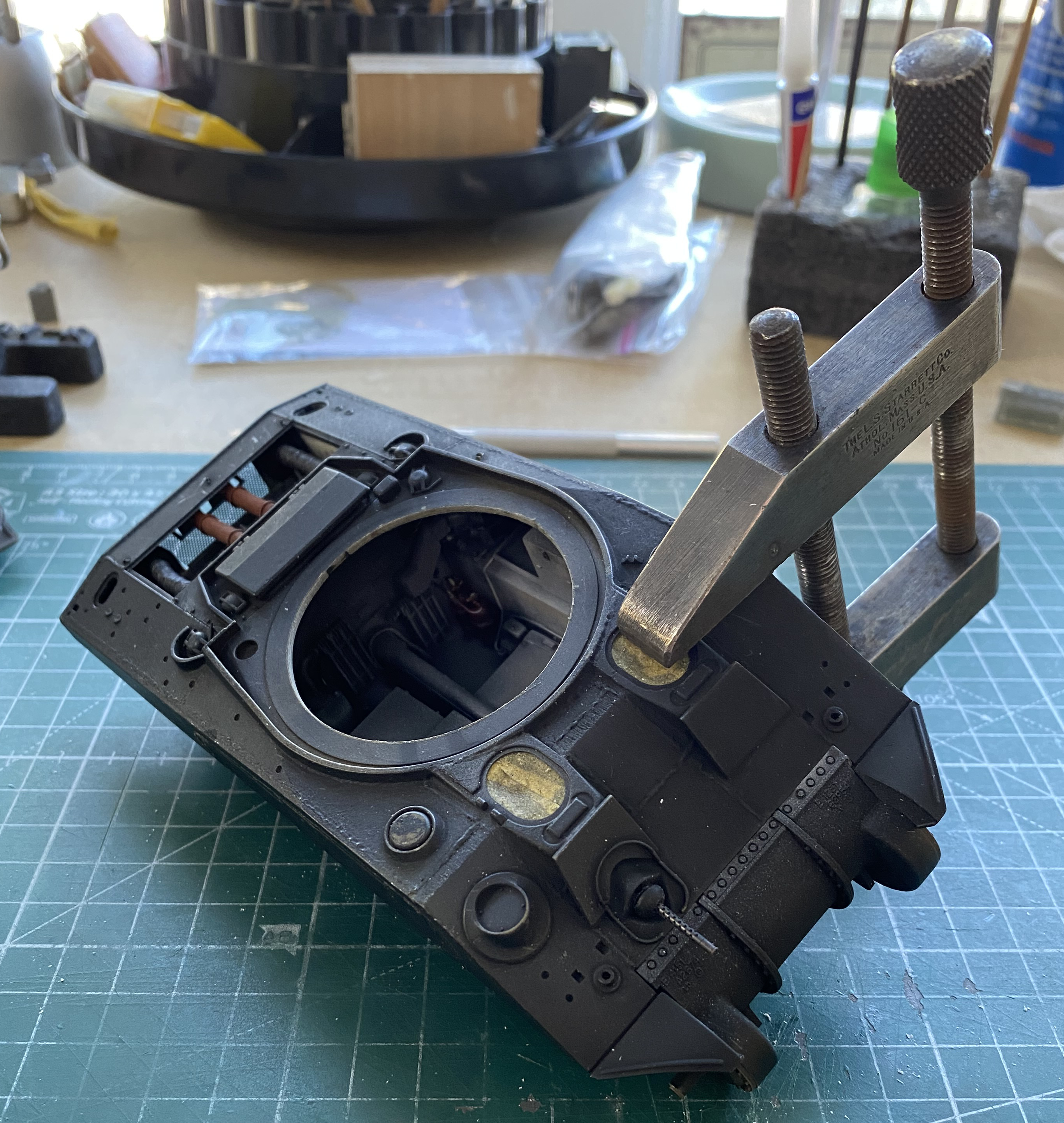
It was at this point that I realized that there really wasn’t anything stopping me, now, from marrying the upper hull to the lower hull. Dry-fitting showed me that there would be A LOT of tweaking and fitting necessary to get these two parts successfully mated. I went, literally, inch by inch. Fit, clamp, glue, go back to the turret basket. There was much rinse and repeating with that (made so much easier by the fact that little of the upper hull was parallel with the sponson bottoms):
Back at the turret basket, that all started with attaching the frame supports to the basket floor:
There were things that had to be added to the basket, much of which had to be assembled (and detailed, of course). This is the gunners turret control unit:
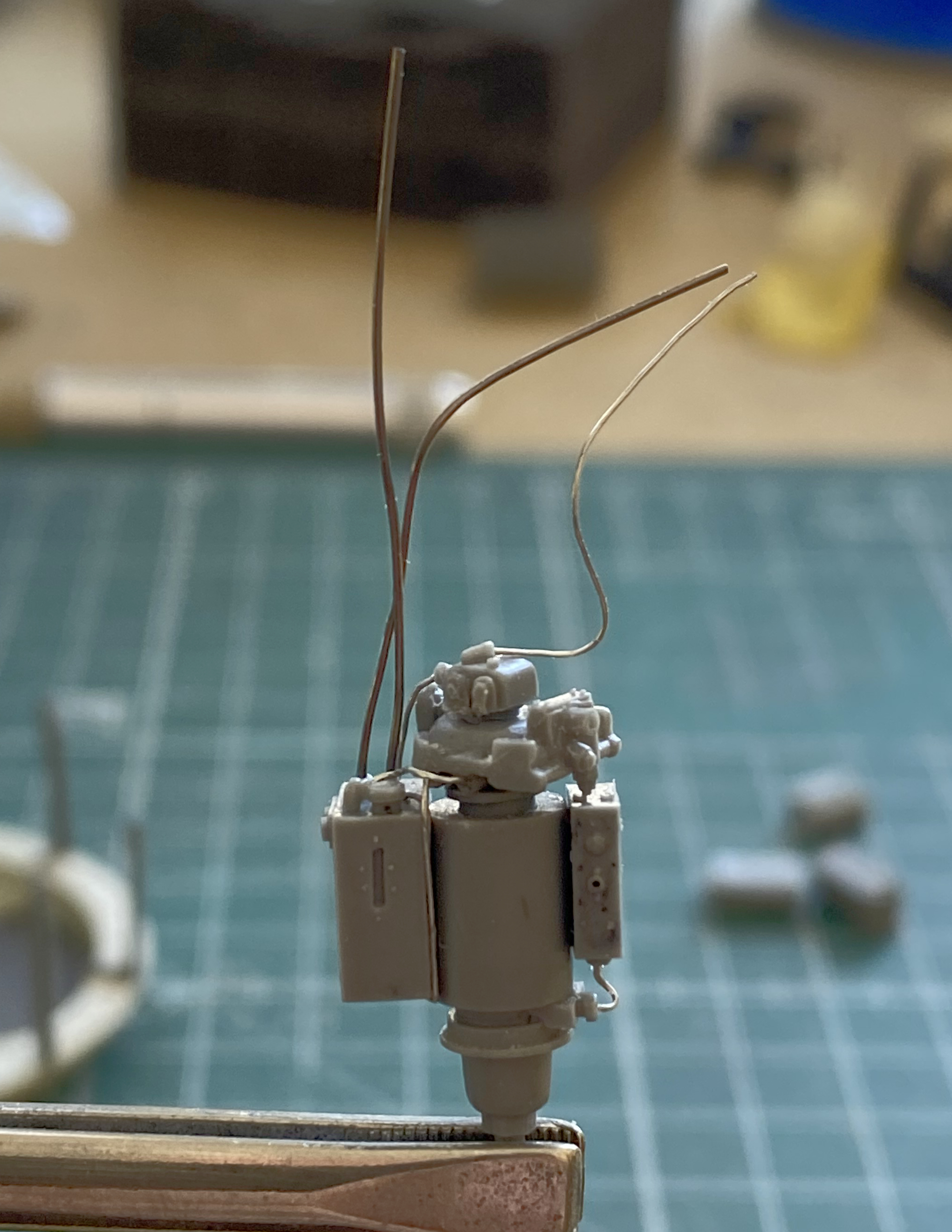
Most of which is there. One part failed to pour and it was the gunner’s control handle which was used to traverse the turret. So I had to make one. I used a piece, a very small piece, of resin from a pour block to carve it to size and shape:
And before that got lost, I glued it in place (the directions are also incorrect with this part…they show this part as upside down as well):
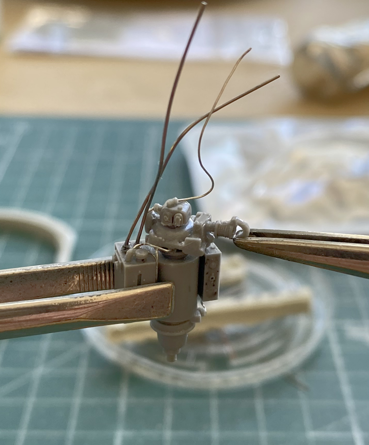
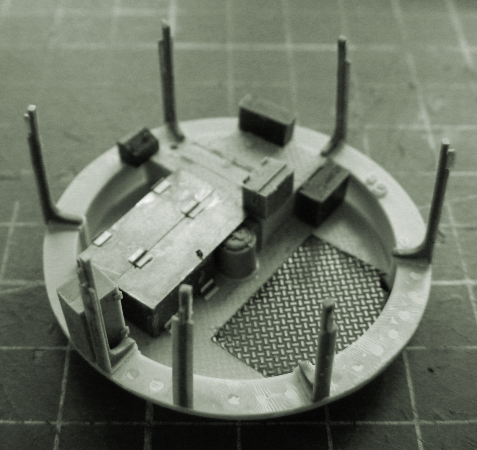
Lots of things were added to the turret basket:
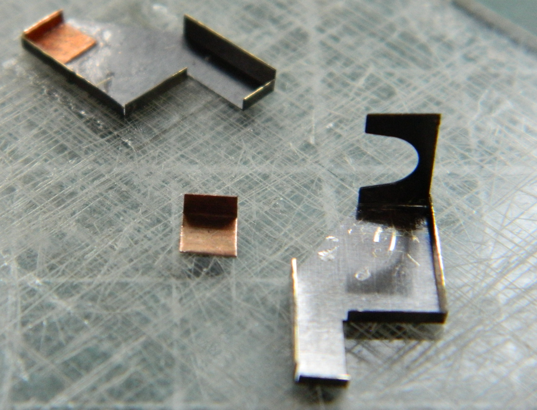
One of the things was a bit or PE that whoever laid this thing out GOT WRONG. There are 9 folds that have to be made. Two of them are attached poorly from the factory. This photo is from the AM set’s directions. Part 10 is poorly, ROTTENLY, laid out:

Between the two larger areas to the right and left, the center part has a large “U” shaped opening. The two larger areas on either side of it are connected to it by ONE TINY POINT on each side. Well, freaking, DUH, you sodding beefwit!! Rotate those two larger areas on either side 90 degrees. Doing it that way would have allowed a much LARGER area to connect those sides to the central part THAT HOLDS THIS WHOLE DAMNED THING TOGETHER. (I suppose it’s…heartening…to see that a beefwit that failed out of engineering school can still find work in the field.)
Fine. This is what they gave me to work with. Fine. FINE. I’ll fornicating work with it, then. I started folding and all was looking good until the last fold (of course). I had an errant hand twitch while hold this thing. (Next person who tries to float this whole “age is just a number” bullshit will be at the receiving end of another “errant” nerve twitch involving my elbow and their solar plexus.) Anyway, the damned thing tore:

And that was the end of that day at the bench!
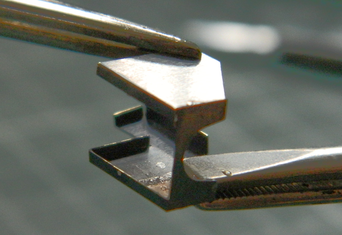
The next day I’d figured out a fix. A small piece of .005″ (.127mm) copper shim stock, bent 90 degrees, and glued in to serve as a larger anchor point (shown braced to a small machinist’s square to ensure that it is IN FACT at 90 degrees,with the part attached to the resin plate underneath it with double-sided tape to hold it in place):

And while I was in the process of doing that, I realized that just because the other side hadn’t ripped free, there wasn’t any chance that it wouldn’t rip free, so let’s fix that before it also breaks:
Then not only did I glue it together and attach it to the basket’s bottom…:


…the whole thing had to be done again because while using a hairdryer to warm the resin posts so I could position them correctly, it slipped out of my fingers and fell. Yep…it landed right on the PE part I’d repaired and came off the basket floor and apart from itself. So I got to do it all again.
‘Kin’ ‘ell.
[So. Do you remember the quiz I’d mentioned earlier? That whole thing about realizing something a bit…late? Here’s where I realized it! This turret basket being of early construction has screened sides. They block the view. In fact, the whole turret basket is going to block the view through the clear panel in the side. Well, well…talk about not thinking something through…sort of like the clear panel in the turret. Being unable to get both sides of that panel parallel, the sodding thing acts like a lens which distorts the view. Lessons learned.]
Clamping proceeded throughout all the above Modeling Magick:
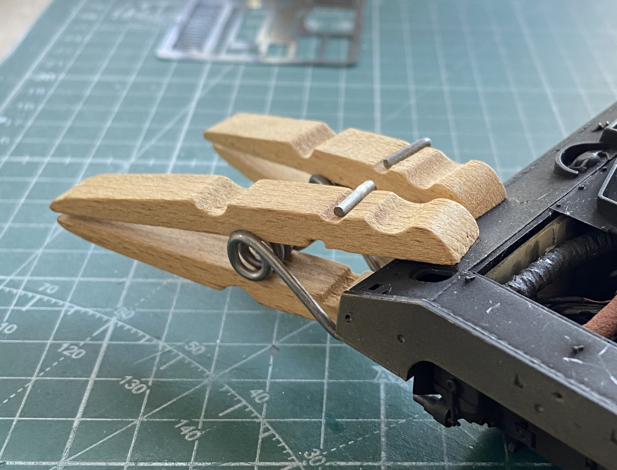
This process was approximate. It quickly became obvious that the best I could get out of this process was a closer approximation of alignment. It wasn’t going to end up being correct. The gaps between the sponson bottoms and bottom of the hull sides were between 0.005″ (127mm) and 0.035″ (.890mm). Most of the sponson bottoms are resin, the extensions at their rear are styrene. To fit scrap styrene into the gaps between resin and plastic required me to glue the scraps to the inside of the hull sides using styrene cement and between the scraps and resin with superglue. Then the clamps were removed, repositioned, and the whole thing done again. And again. Each side required four clamping sessions. This is the first side in process:

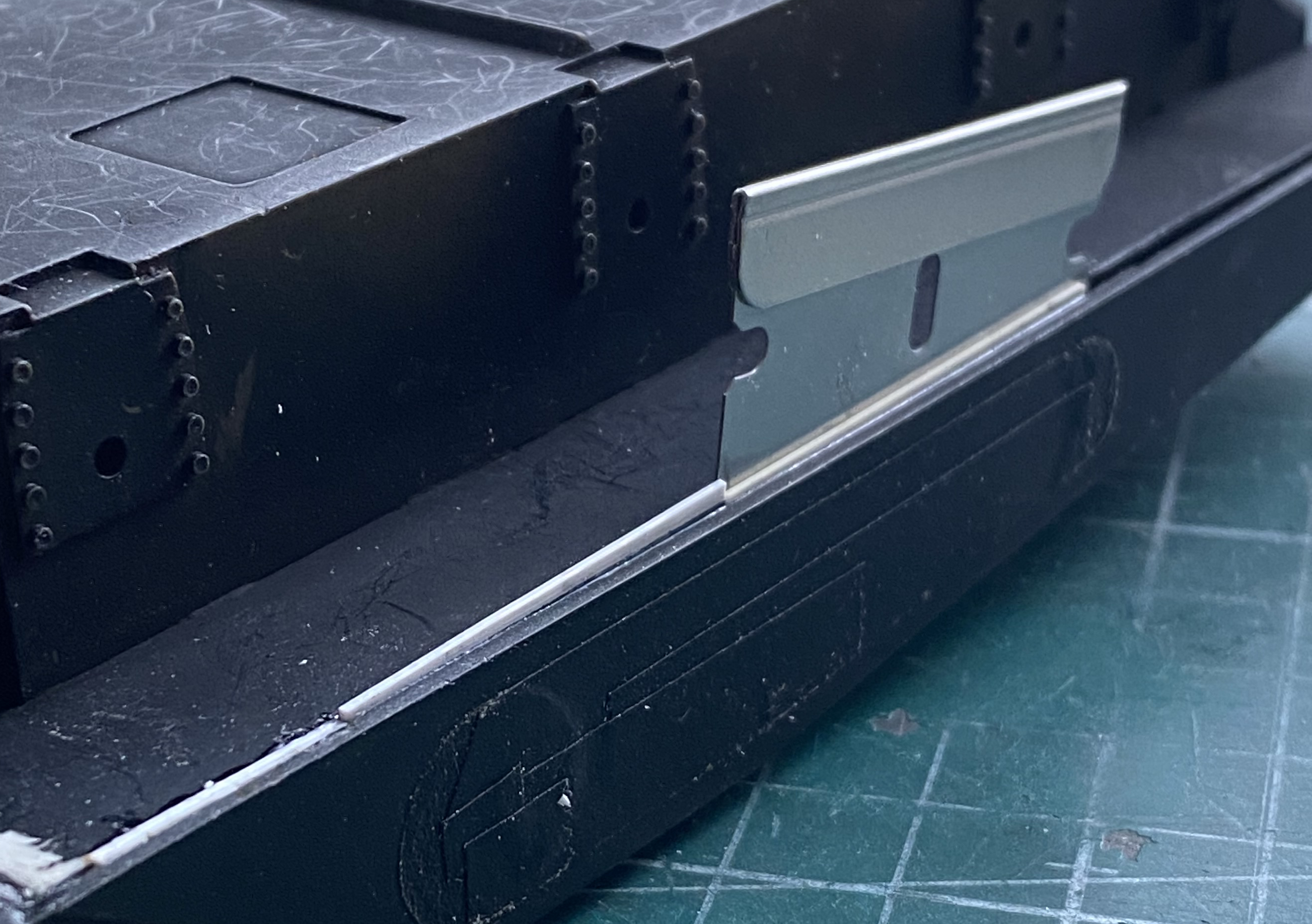
I remembered to take photos of the second side to show what I was dealing (successfully!) with. Gaps and a razor blade to apply pressure to the outer side where the scrap is pressed against the hull:
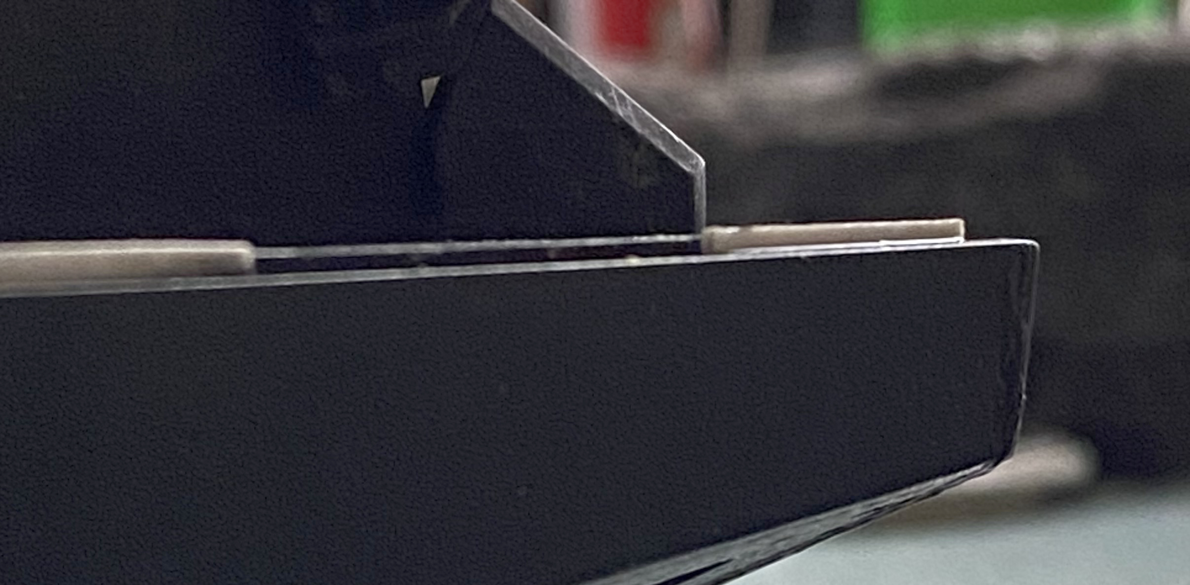
A better look at this gap (the other side was worse, if y’can believe that):

Not only were the sides out of alignment laterally, they were also out of alignment vertically:
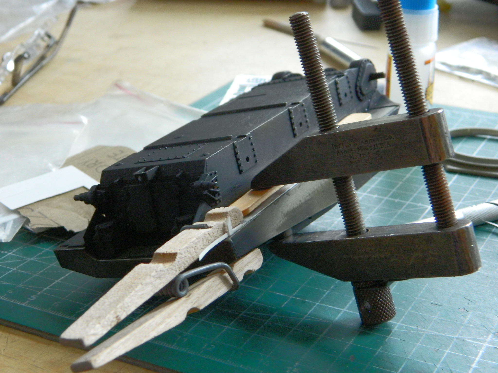
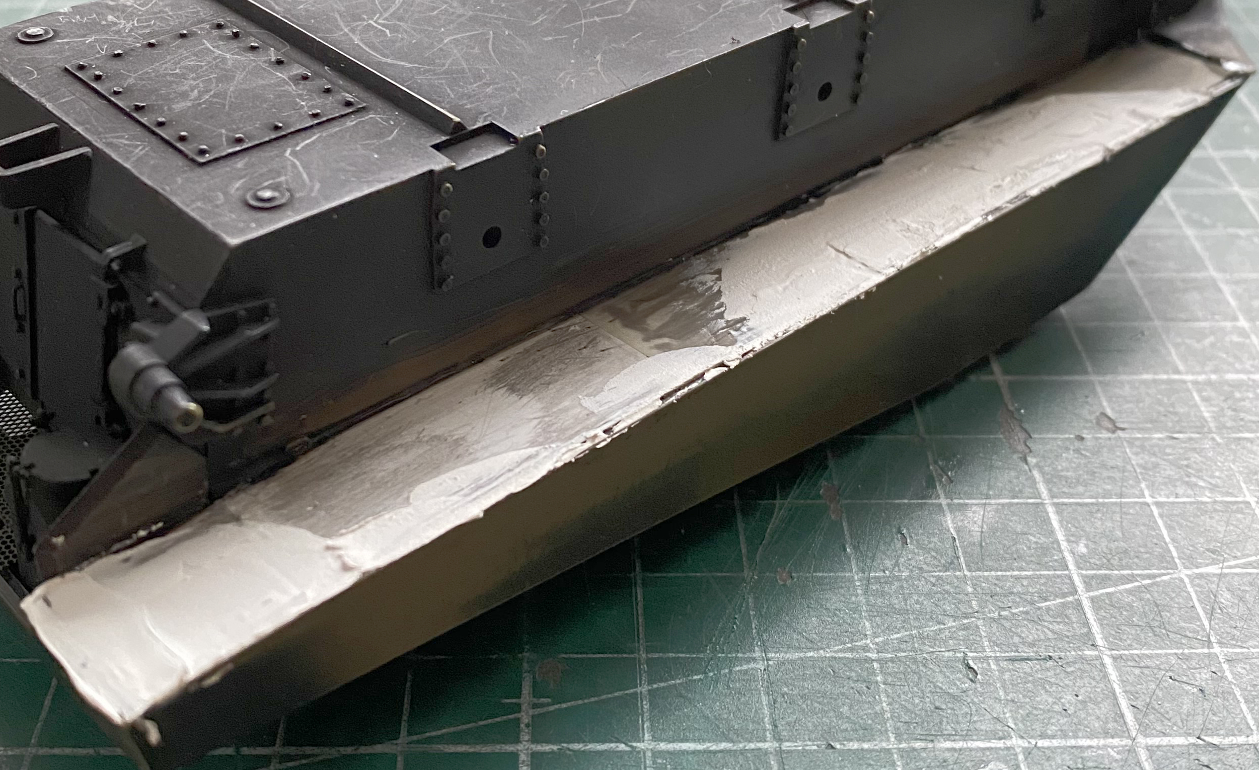
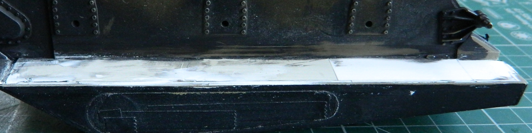
Clamping under significant pressure (I figure when the thing starts creaking it’s time to stop adding more pressure) and lots of filing (filed because the surface is supposed to be flat and a file’s face is flat), and several sequential applications of putty along the entire lengths gets to this:
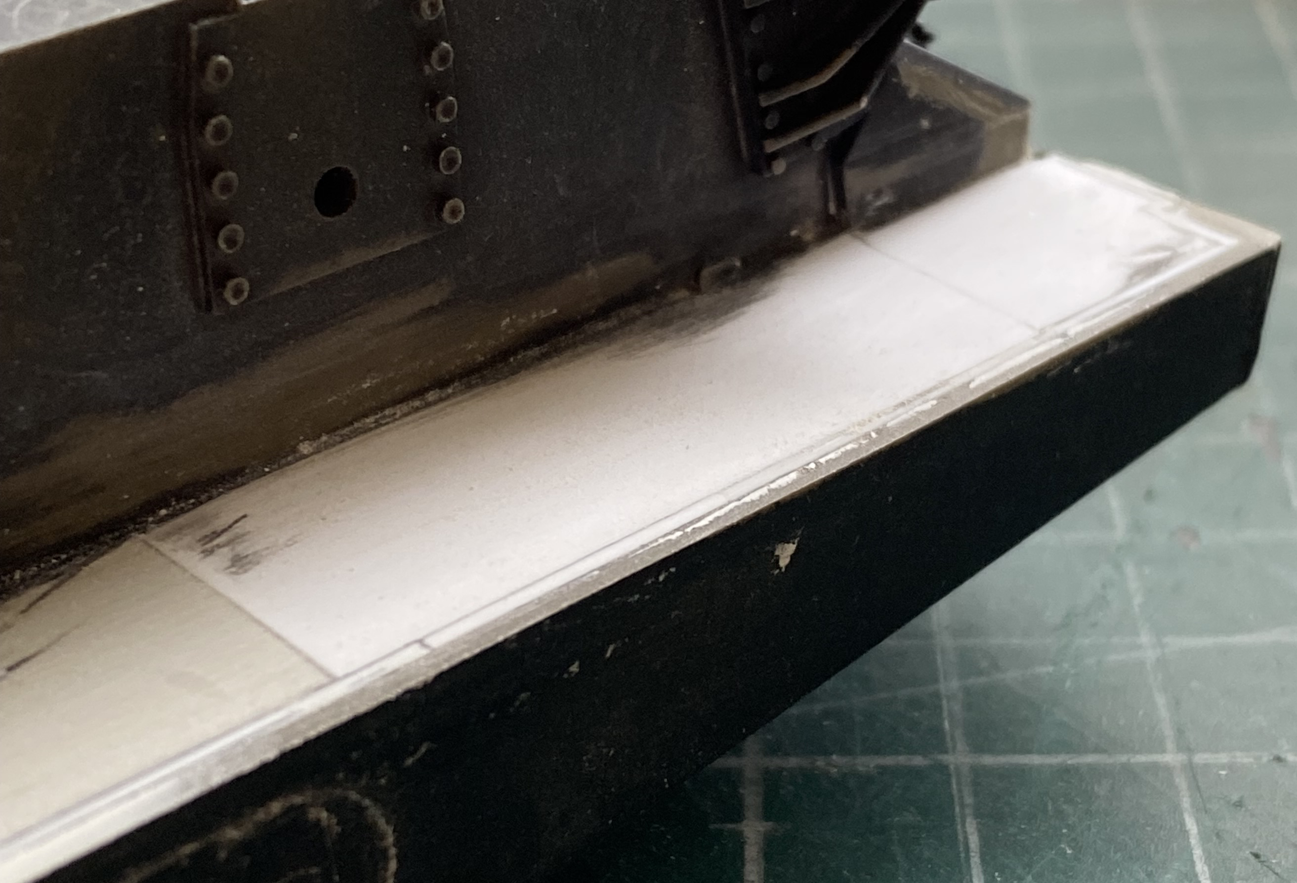

The sponson bottoms are supposed to be at 90 degrees to the lower hull sides. They aren’t. The sponson bottoms are supposed to be flat. They aren’t. But they look as if they are, and this is now before any application of paint. Both the lower hull and the sponson bottoms will be mostly flat black with a very faint misting of OD Green. Suspension, bogies, road-wheels, and tracks will fill most of that space. The end result (which is the goal, remember) will be that the sponson bottoms will look like they’re at 90 degrees to the hull bottom’s sides and look like they’re flat.
And that’s what Modeling Magick really is…making something look like something it won’t ever be.

Oh, the patience of a saint . . . Excellent work.
LikeLike
Yeah? Wait’ll you see next month’s post. In short, now that I have the basic shape/dimensions of the turret basket, I could check its fit. It doesn’t. One of the boxes in the interior had to be moved…except it will not budge. I have to figure out how to move it because at approaching 300 hours there’s too much time invested on it to walk away from it. So I’m temporarily stepping back until I figure out *how* to fix it.
LikeLike