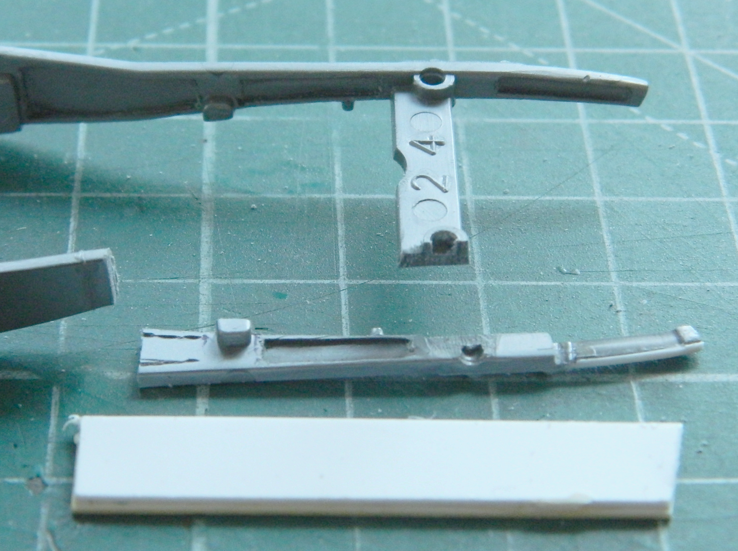
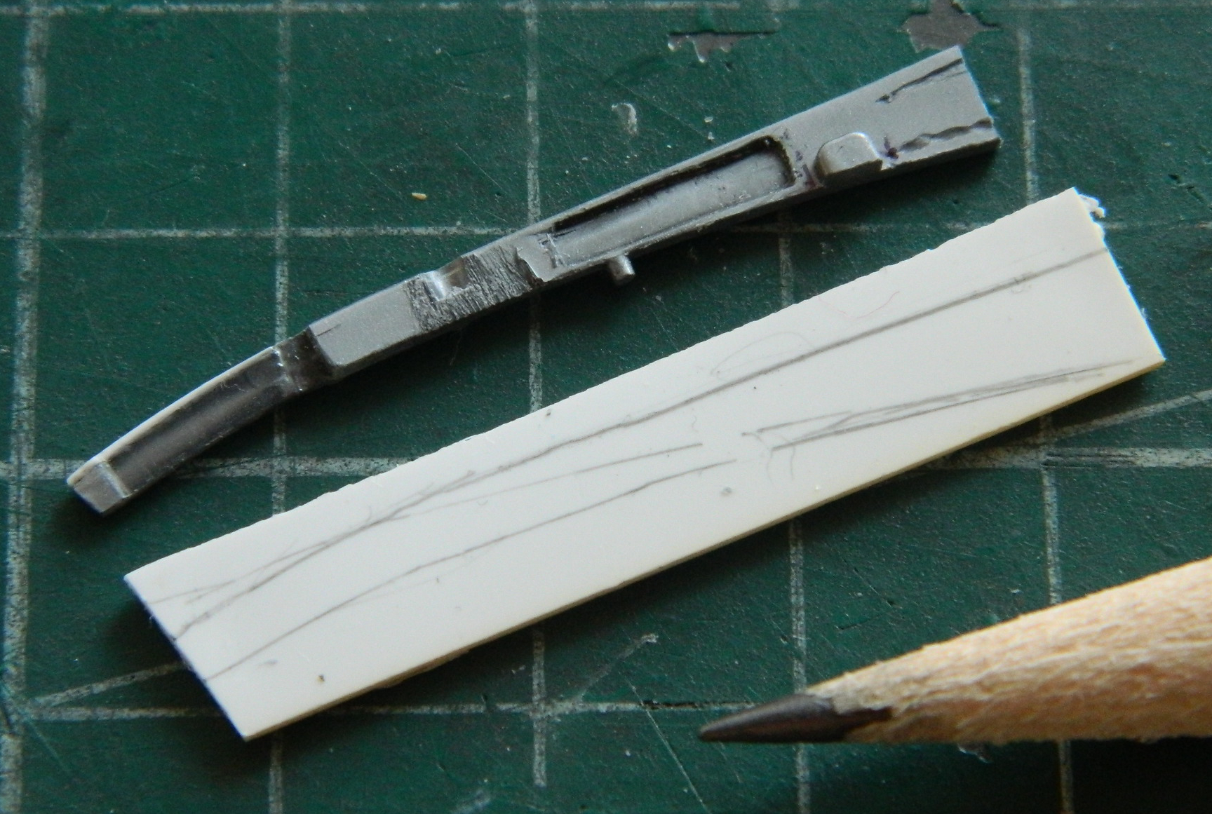
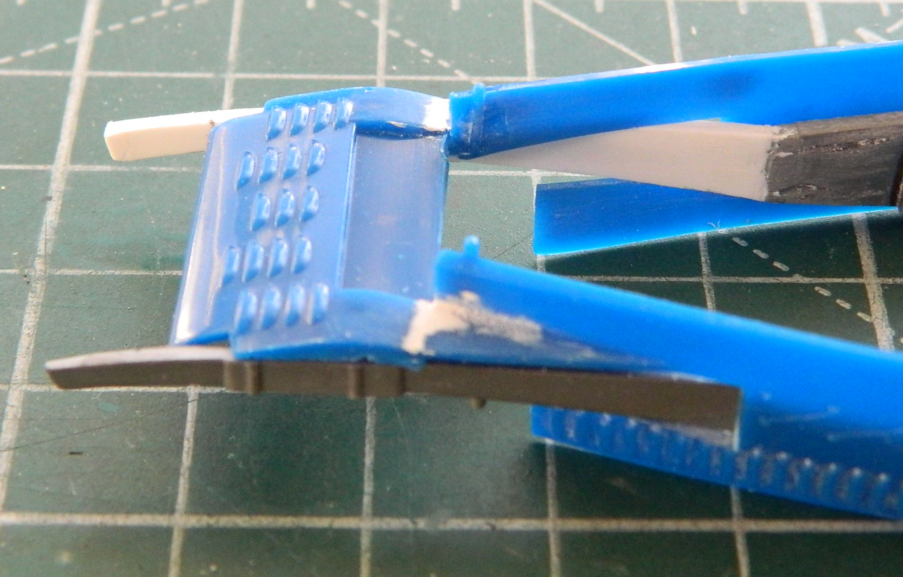
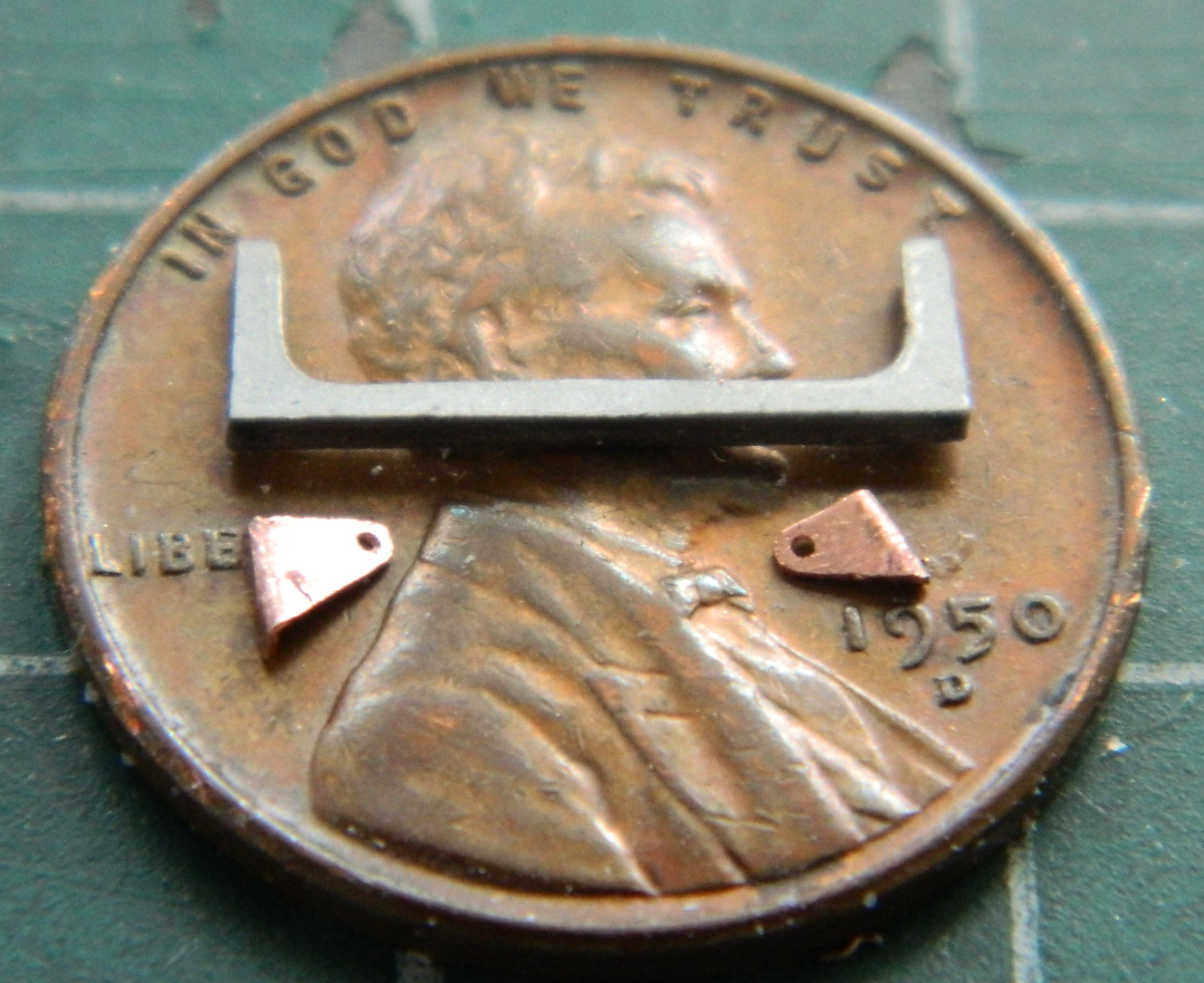
Having broken off the right front section of the frame, fixing that bit took my attention. I needed a section of plastic that was .050″ (1.27mm). To get that thickness, I used a section of .060″ (1.542mm) which I will sand down later and traced the section of frame rail I needed to replace. I had already determined that the part I broke off wouldn’t stay attached when glued (very small surface area for the glue) so I cut the damaged frame section back to an area that offered a greater surface area for the glue to work with, then I traced the profile of the undamaged section of frame to the new styrene:
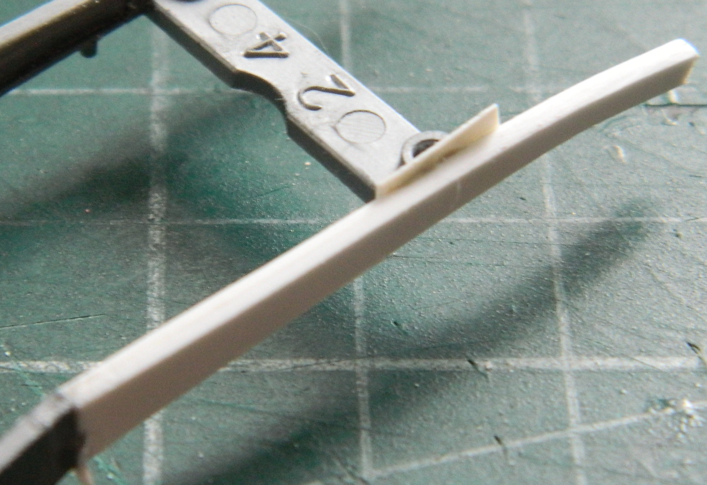
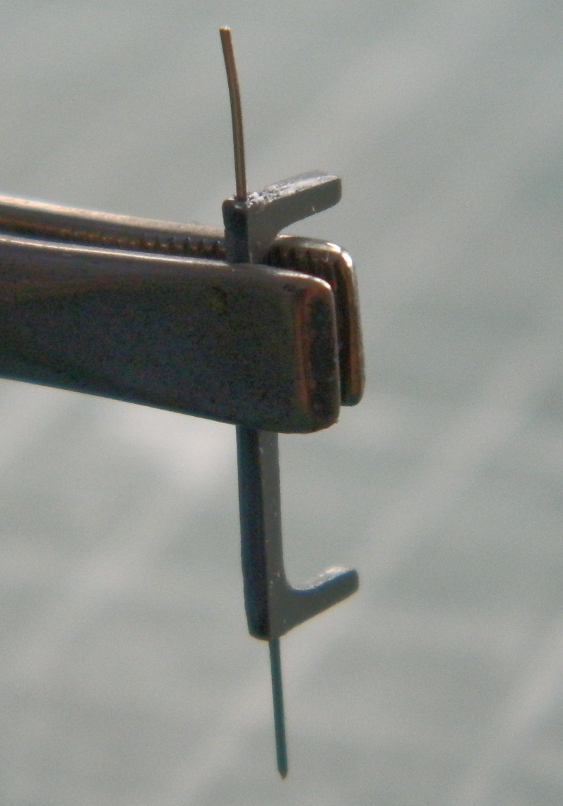
Once trimmed, I added a section of .010″ (.254mm) to where the cross brace meets the frame to replace the kerf where the frame rail had been sawed off:
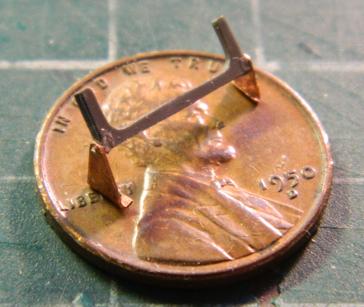
Then I used scraps of styrene of varying thickness to fill in areas that had gaps. I used the styrene scraps for strength; this time it had to look correct and be structural:
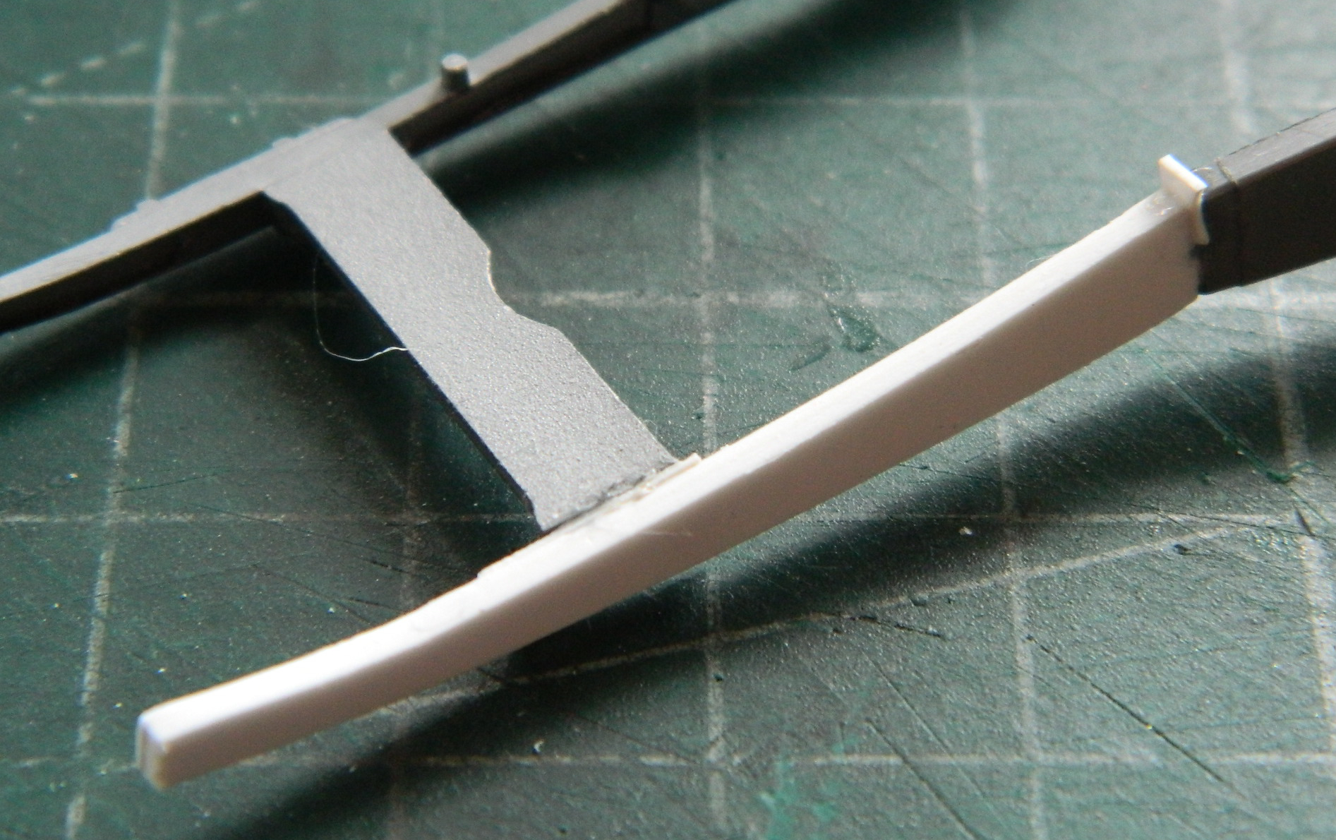
Then I put the frame into the body to see how well things lined up (fairly well):

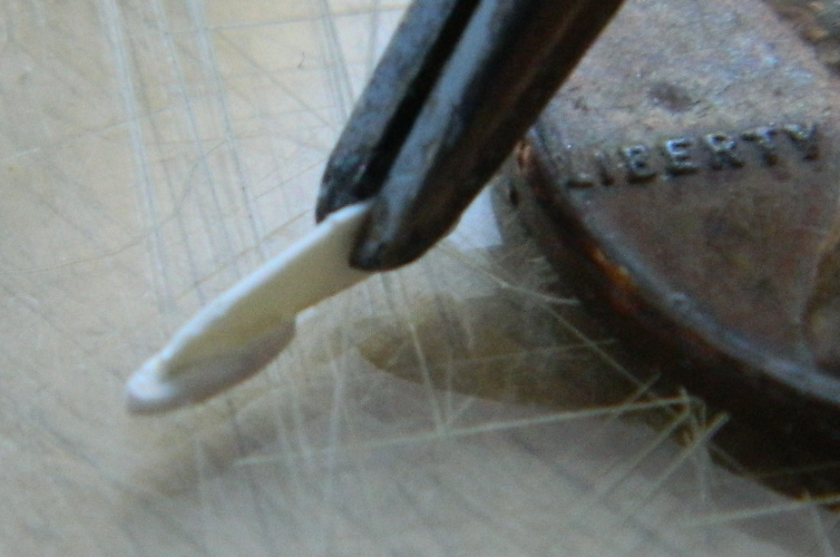
At this point I filed and sanded the profile of the new frame section to fit the profile needed more accurately and to bring the new section down to the needed thickness.
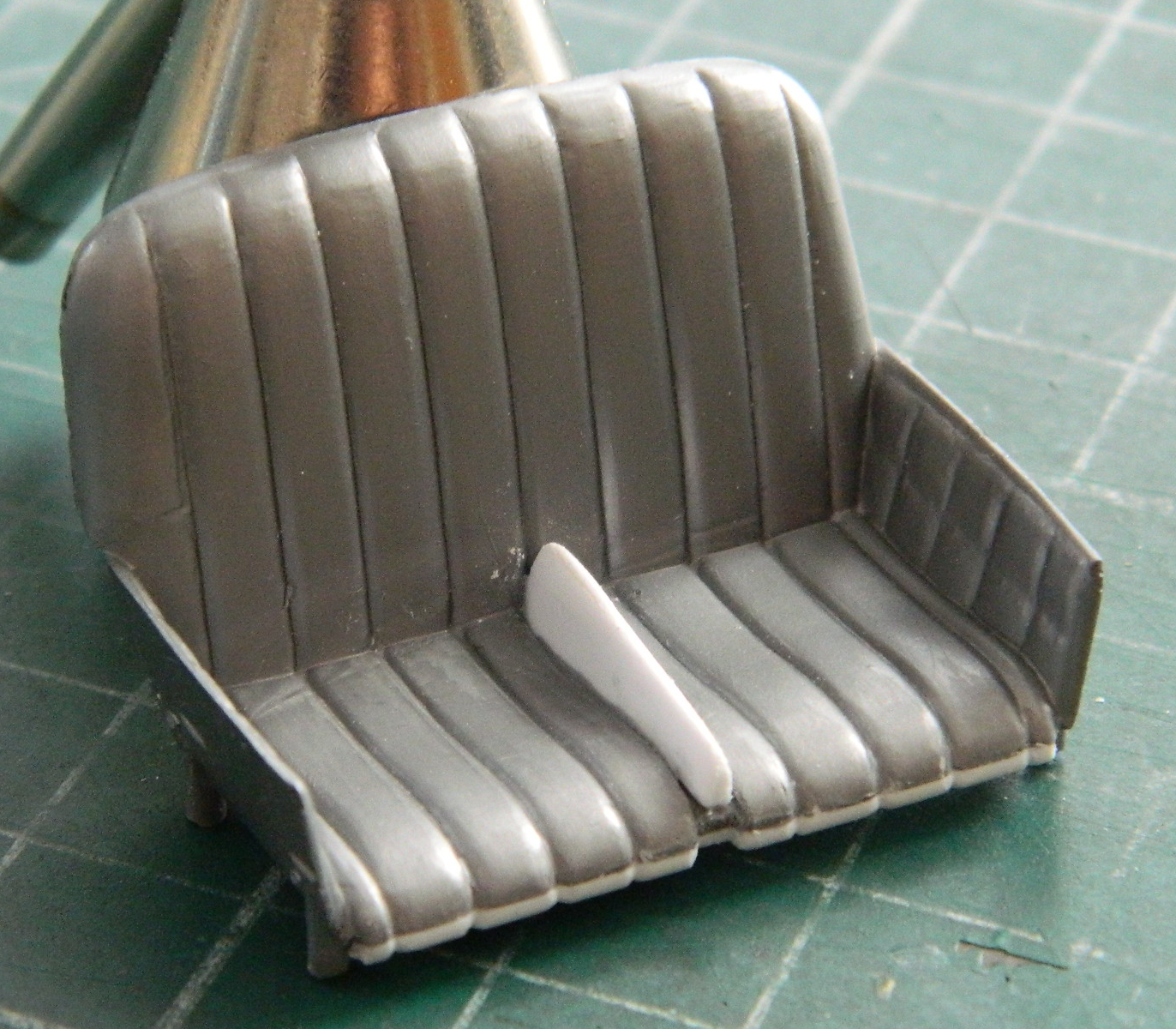
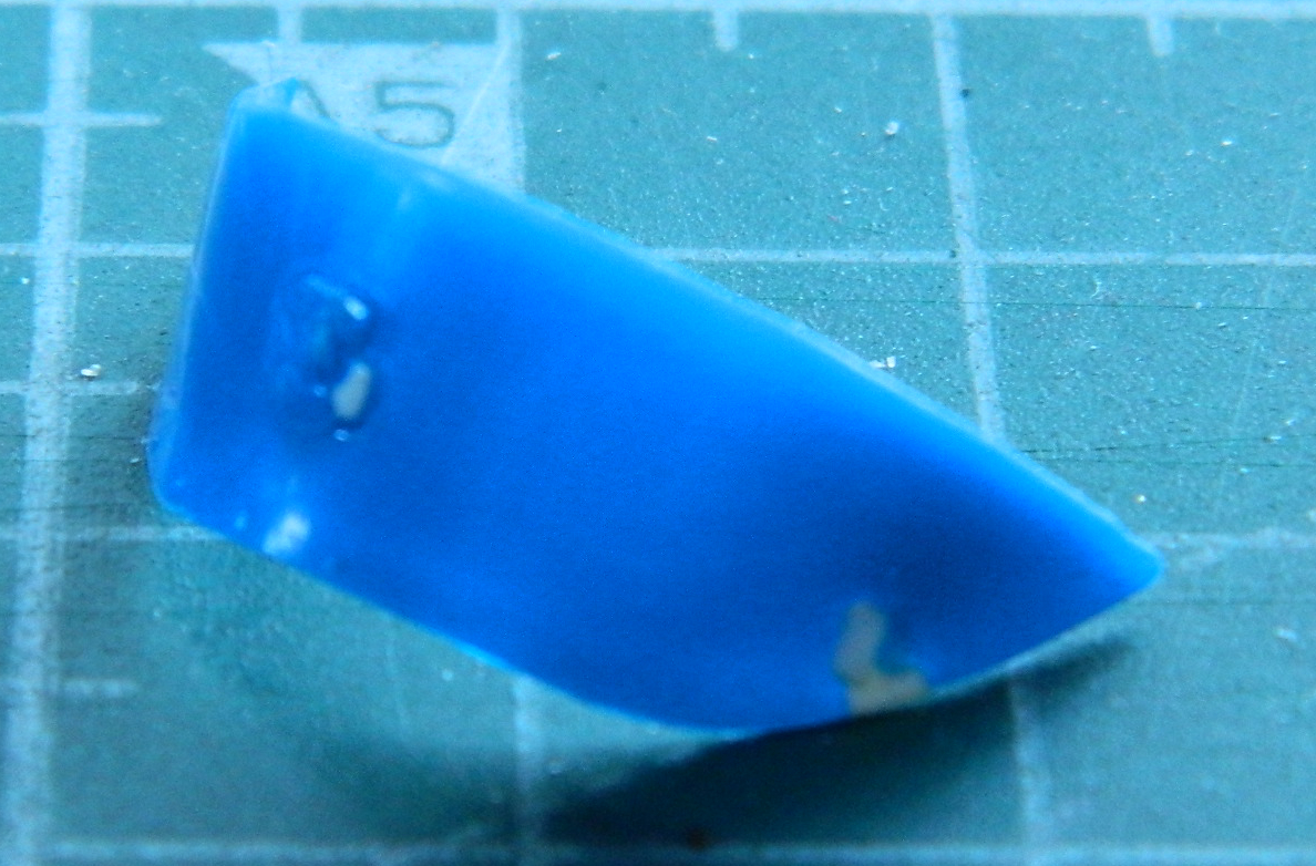
I started working on the seat that I had cut away the thermal blanket section off of. I added a strip of .060″ (1.524mm) to the lower front edge so that I had the material in place to create a more finished look for that section of the seat than the abrupt edge that resulted from removing the front of the seat left:

A little knife and file work finished that area (not the best photo of the results, unfortunately):

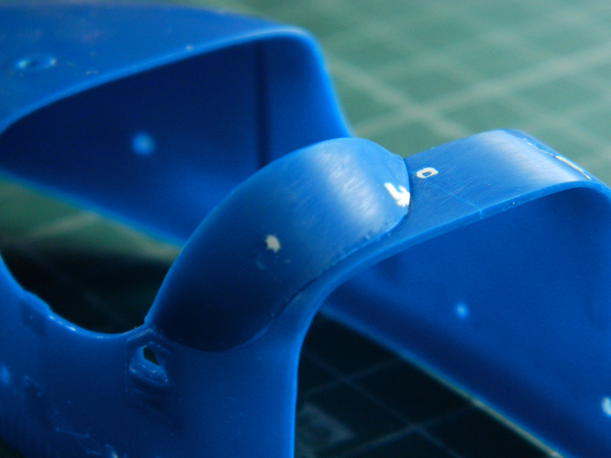
While looking at reference photos, I noticed that it was not at all uncommon for a partition to be added to the seat, evidently to keep the driver at the controls and out of the mechanic’s lap (before they stopped having mechanics ride with them during a race). I added .060″ (1.524mm) again by slotting the seat and then trimming the addition to shape (and though not evident, I also started adding “compression” to the padding by sanding down the areas where the drivers’ weight would cause the packing material…probably horse hair…in the padding to compress):
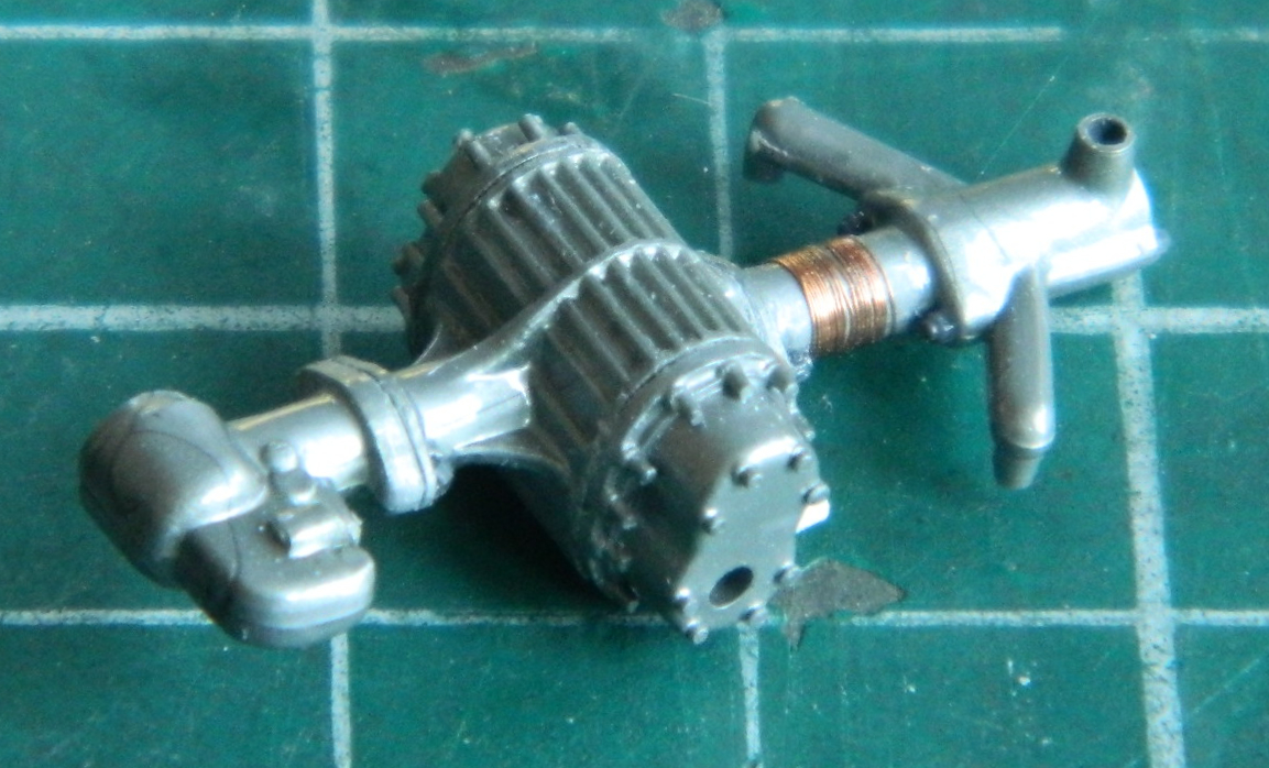
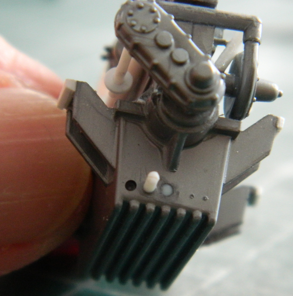
I started adding additional details to the supercharger by adding Grandt Line bolts, 48 gauge wire wrap around the tubing connecting the supercharger body to the over-pressure blow-off port, and running a panel line scribe where the parts of the ducting connecting to the supercharger would show a seam when parts were connected:
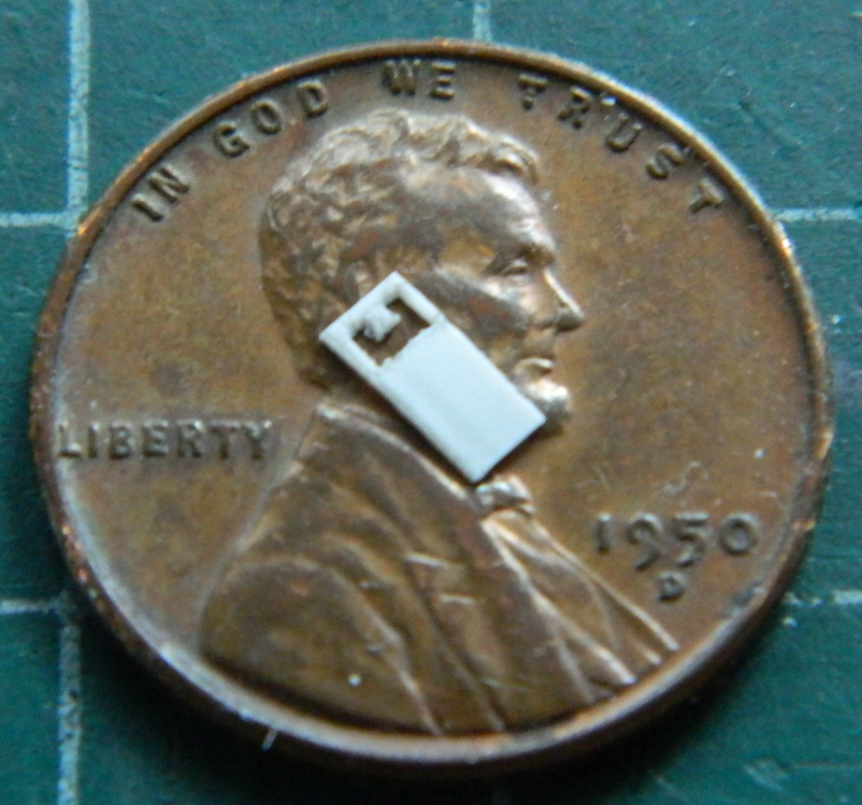
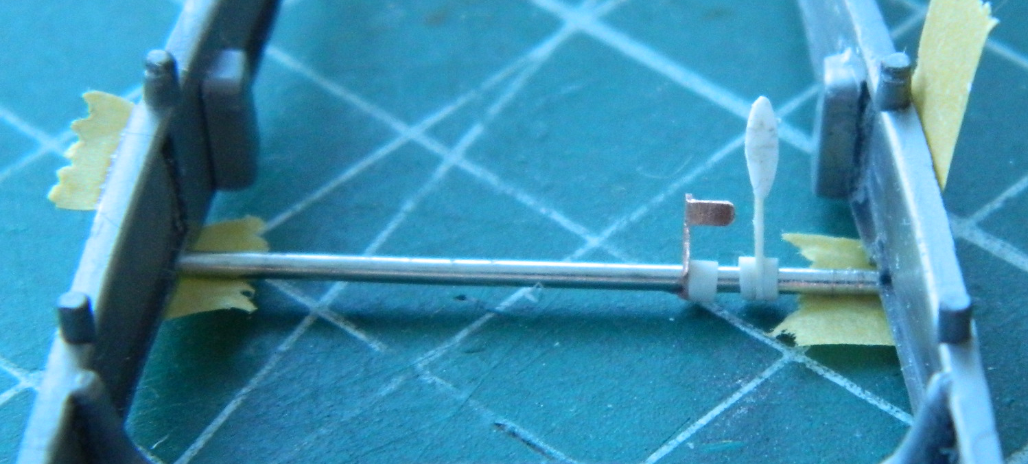
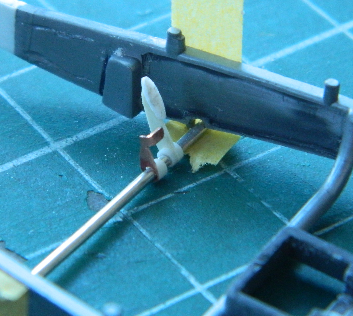
Then I started making the linkage. There are two linkage arms at each end of the blower body. I used .005″ (.127mm) aluminum foil to make the linkage levers. I drilled holes first and then used a straight razor blade to cut the foil around the holes. With the levers slid over the .010″ (.254mm) wire, a drop of superglue fixed them in place:

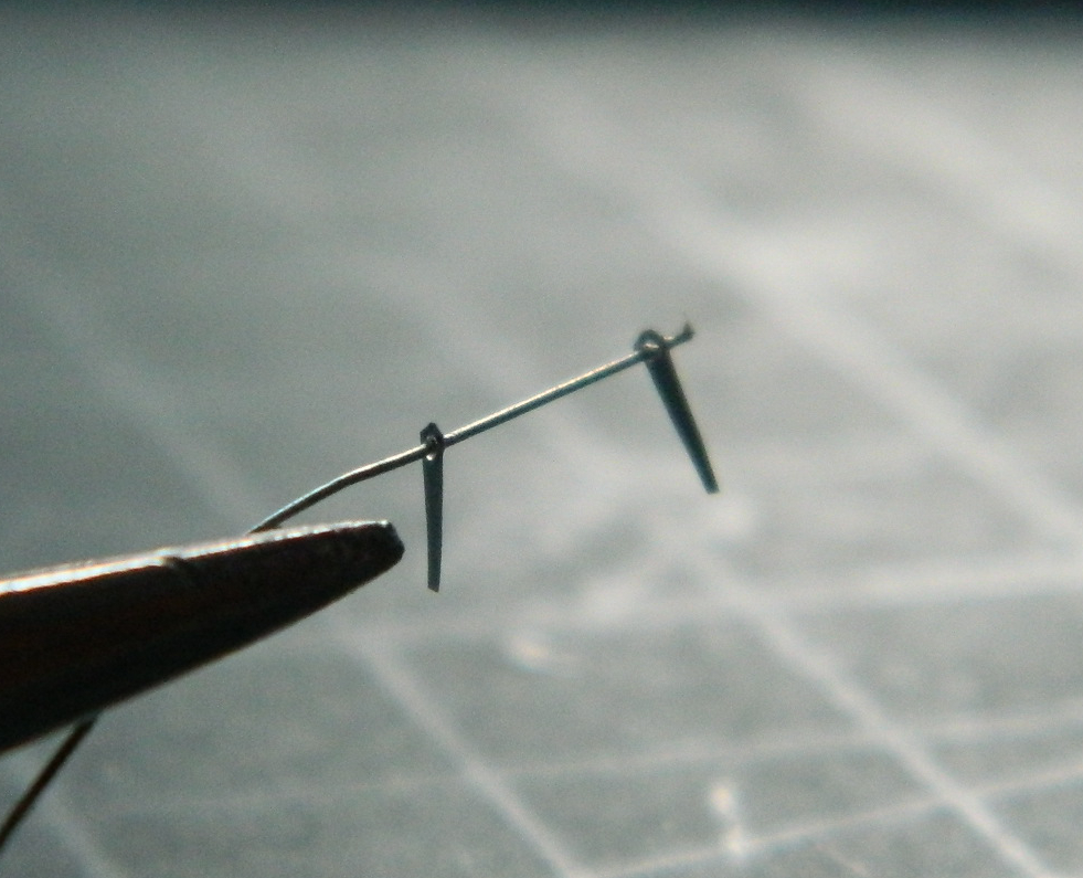
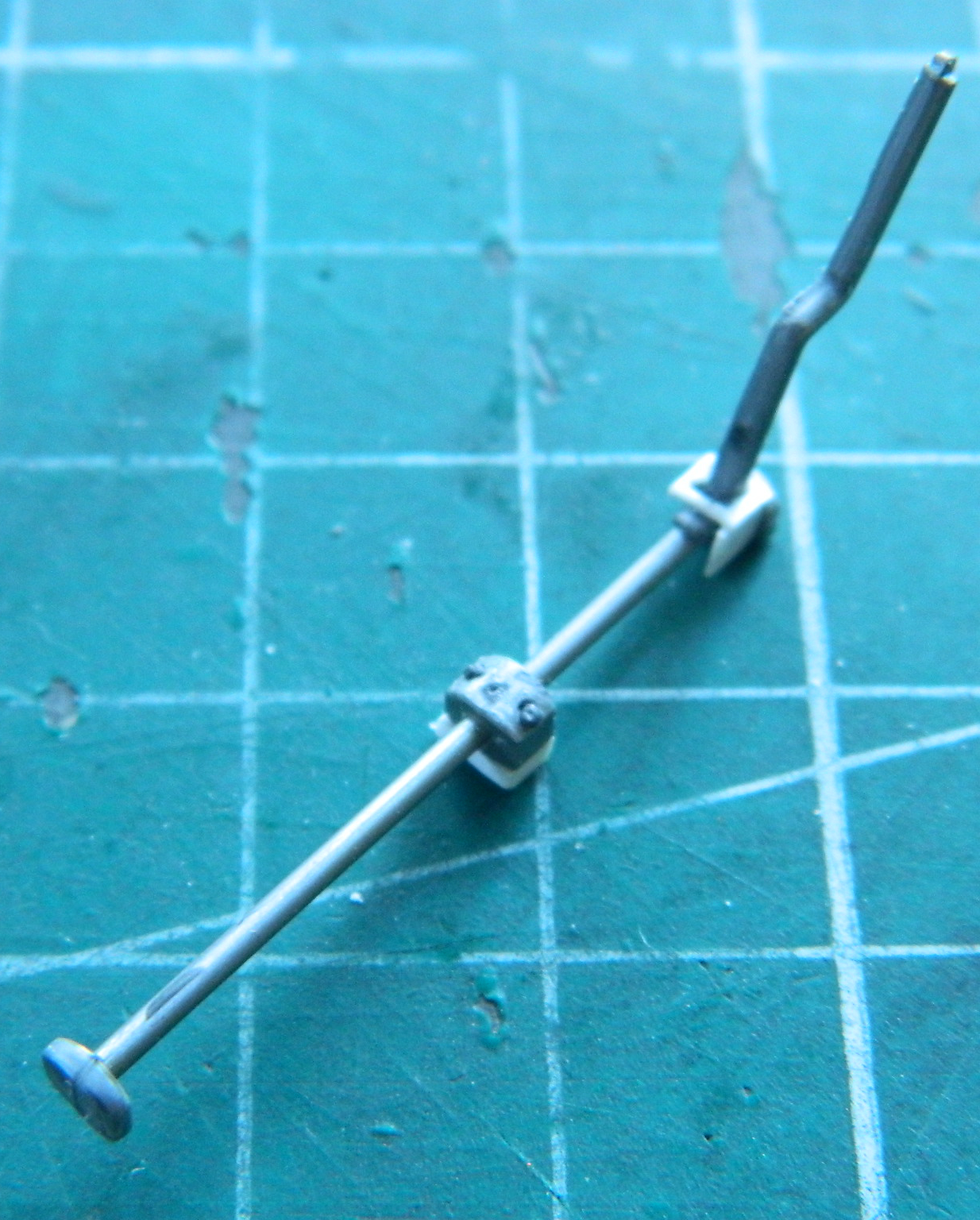
After letting the superglue cure overnight, I trimmed the linkage shaft to separate the two arms, added the resultant lever shafts to drilled out styrene rod I’d added to the body of the supercharger, then dropped another .010″ (.254mm) wire across the levers. I glued them in place and then used a nail trimmer to snip the excess aluminum from the levers:

The remainder of the throttle linkages will be added once the supercharger is added to the engine and then all that installed into the frame.
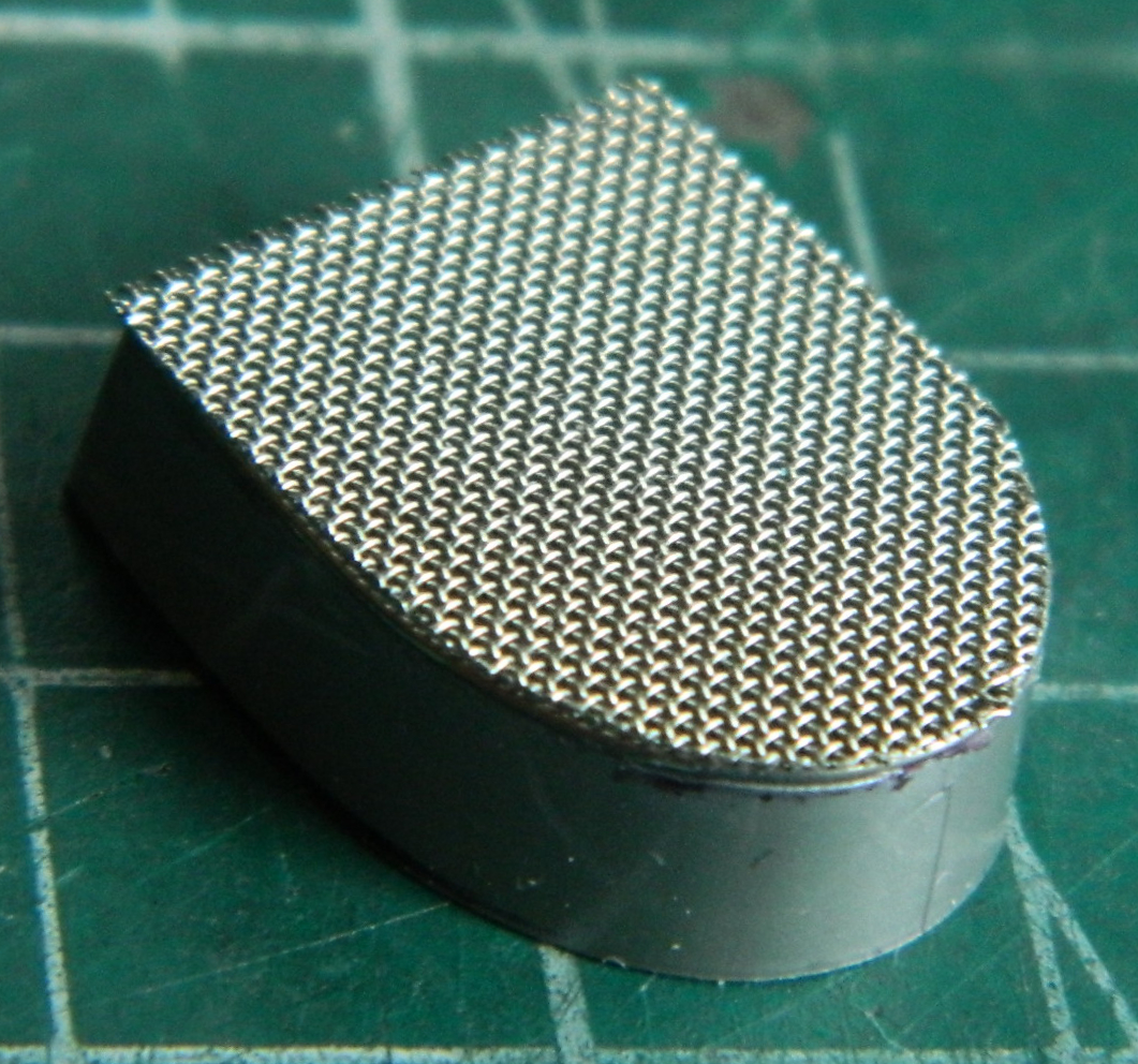
The race cars had a screen added in front of the radiator. I added a length of .015″ (.381mm) solder to the periphery of the radiator to serve as the screen’s mounting:
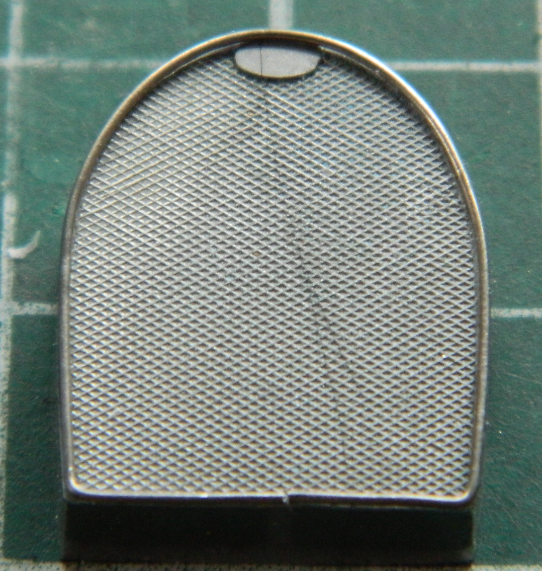
Then I trimmed some stainless steel screen I have to fit over it:
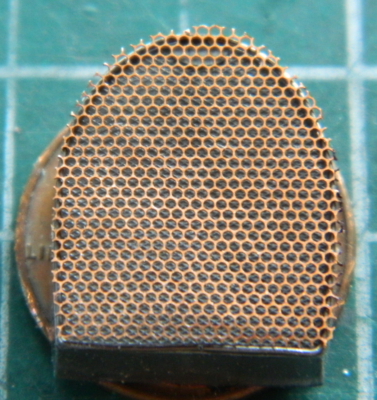
To my eye, the wires of the screen are too thick. I rummaged through my “stuff” supply and found a sheet of PE screen which was trimmed and fit (more trimming was done later than the photo below shows):
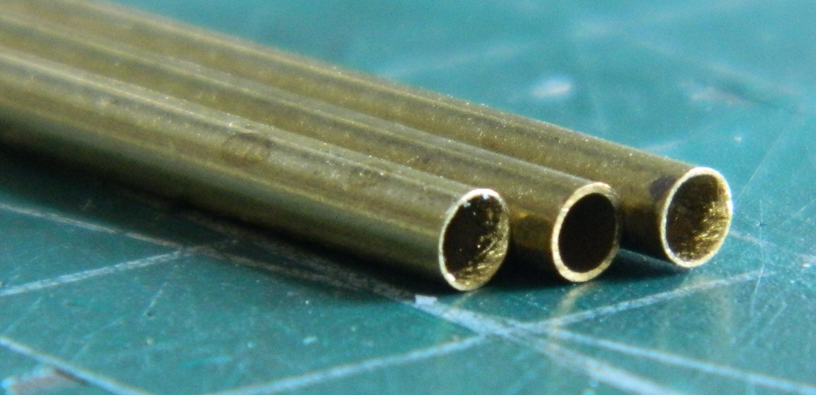
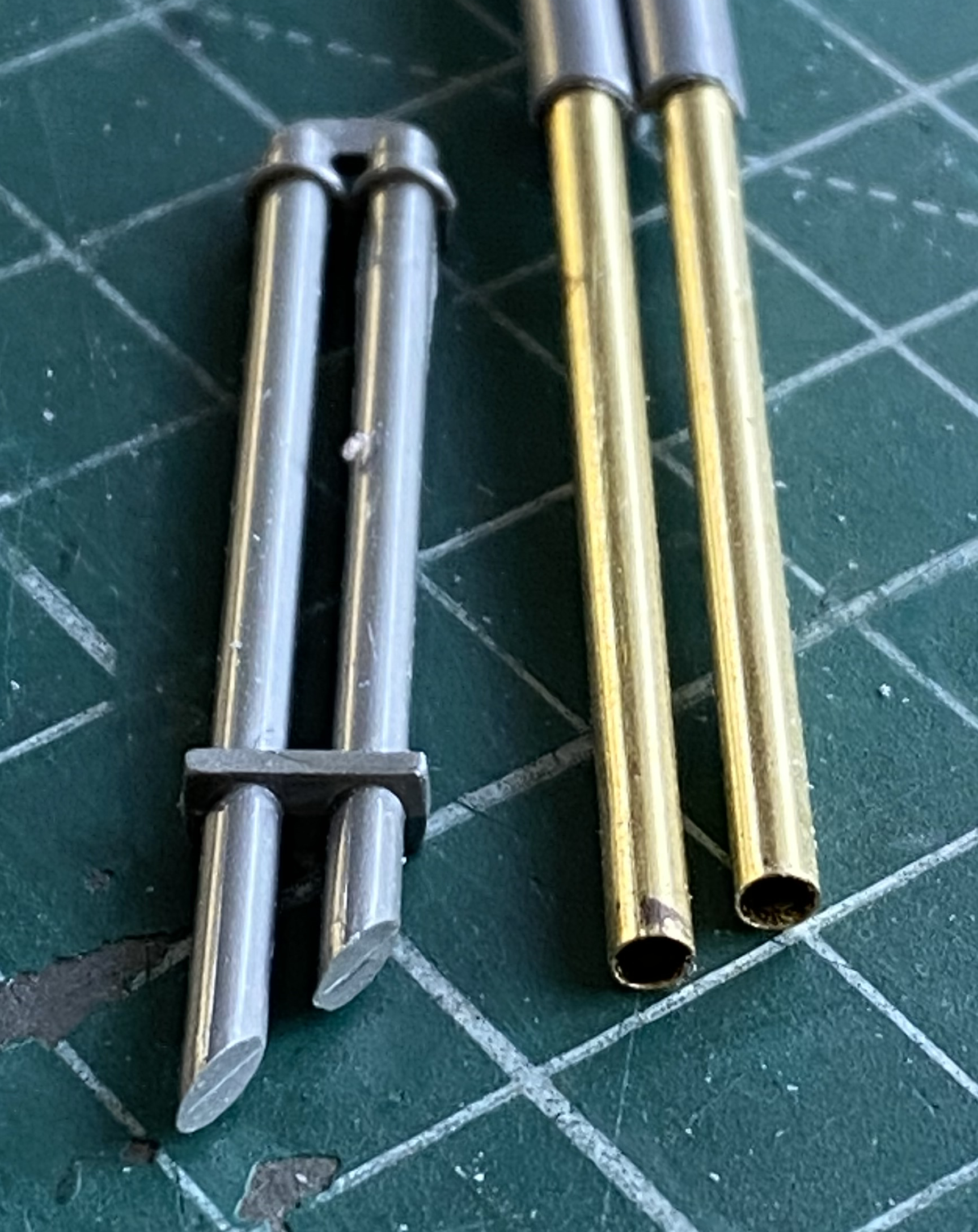
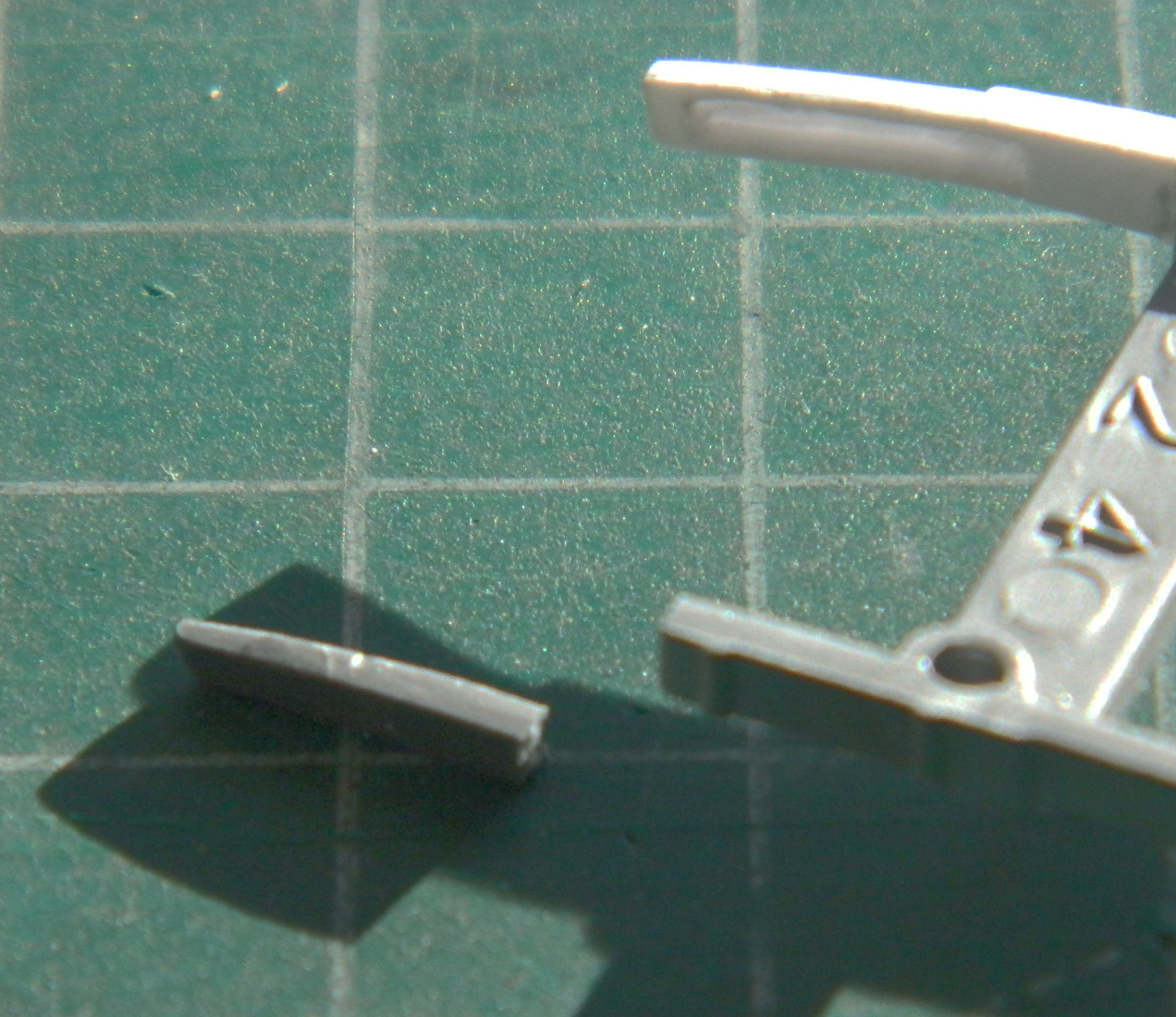
I had intended originally to drill out the ends of the exhaust pipes. Perhaps these type of pipes were used on road cars; they weren’t used (as far as my reference photos show) on racing cars. Luckily I had just enough of the correct diameter brass thin-wall 3/32″ (2.5mm) tubing to replace the solid plastic “pipes.” Even being thin-wall tubing, the thickness of the tubing walls needed to be thinned further. The unmodified tubing is in the center in the below photo. I thinned the walls to about .008″ (.2mm) using a very fine and pointed rat-tail file:
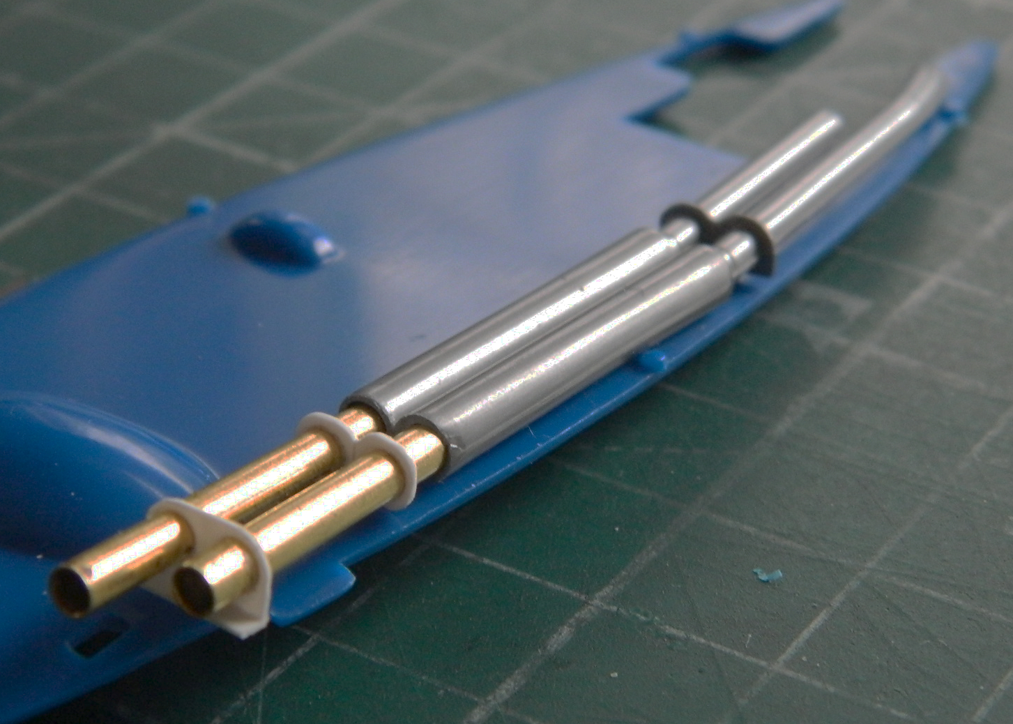
I drilled out the ends of the mufflers to accept the round tubing:
Reference photos show the pipes ending under the body of the car instead of extending past it so brackets and hangers had to be made and the tubing shortened. The bracket closest the muffler was made from .015″ (.381mm) styrene and the hanger near the tips made from .015″ (.381mm) for the mount and .010″ (.254mm) for the bracket:
The shifter, one of the levers hanging out of the cockpit on the right side (the other, taller one, is the parking brake), is a gate shifter (Ferraris frequently use those, if you’re interested) (and Ferraris frequently use those even if you aren’t interested). The kit kind of vaguely attaches the shifter arm to the shifter “linkage” without one, so I had to make one. I used .010″ (.254mm) scrap to do so:
I also added Grandt Line bolts to where the shifter linkage attaches to the transmission as well as the connecting housing under that section:
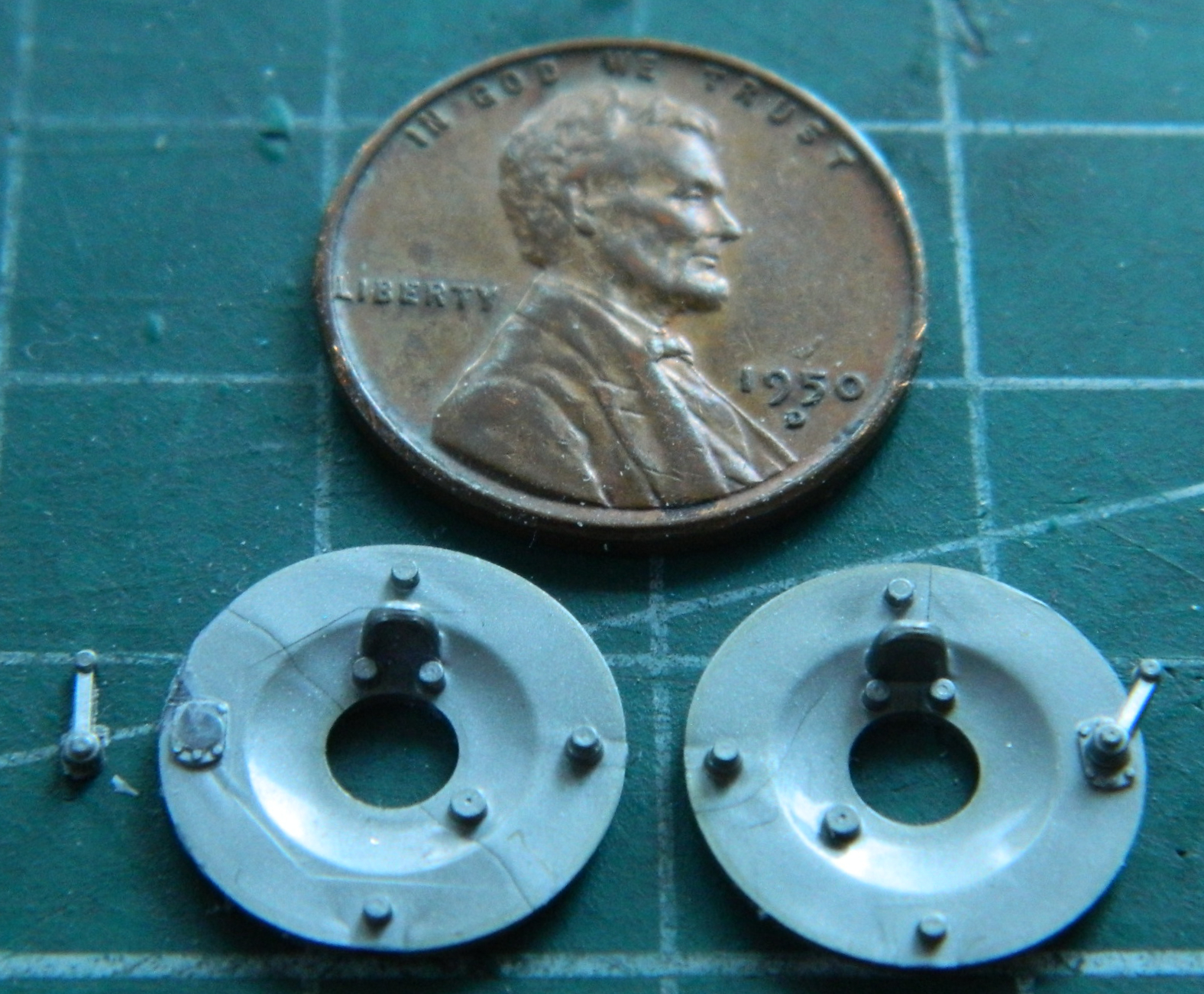
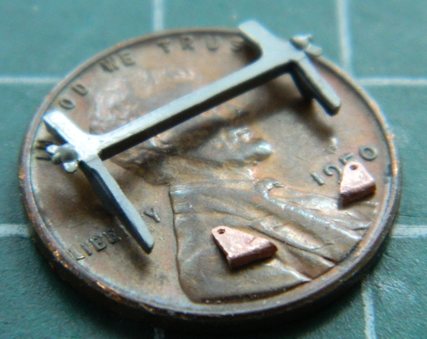
Earlier Bugattis used cable operated brakes instead of hydraulic brakes. Many early cars did, Bugatti was just one of the last hold outs to make the switch to hydraulic brakes (“I build my cars to go, not to stop,” he’s credited with stating). The levers for those cables on the brake backings were molded to the backings and should stand off of them on a shaft. The first step was to carefully cut the levers away from the backing plates:
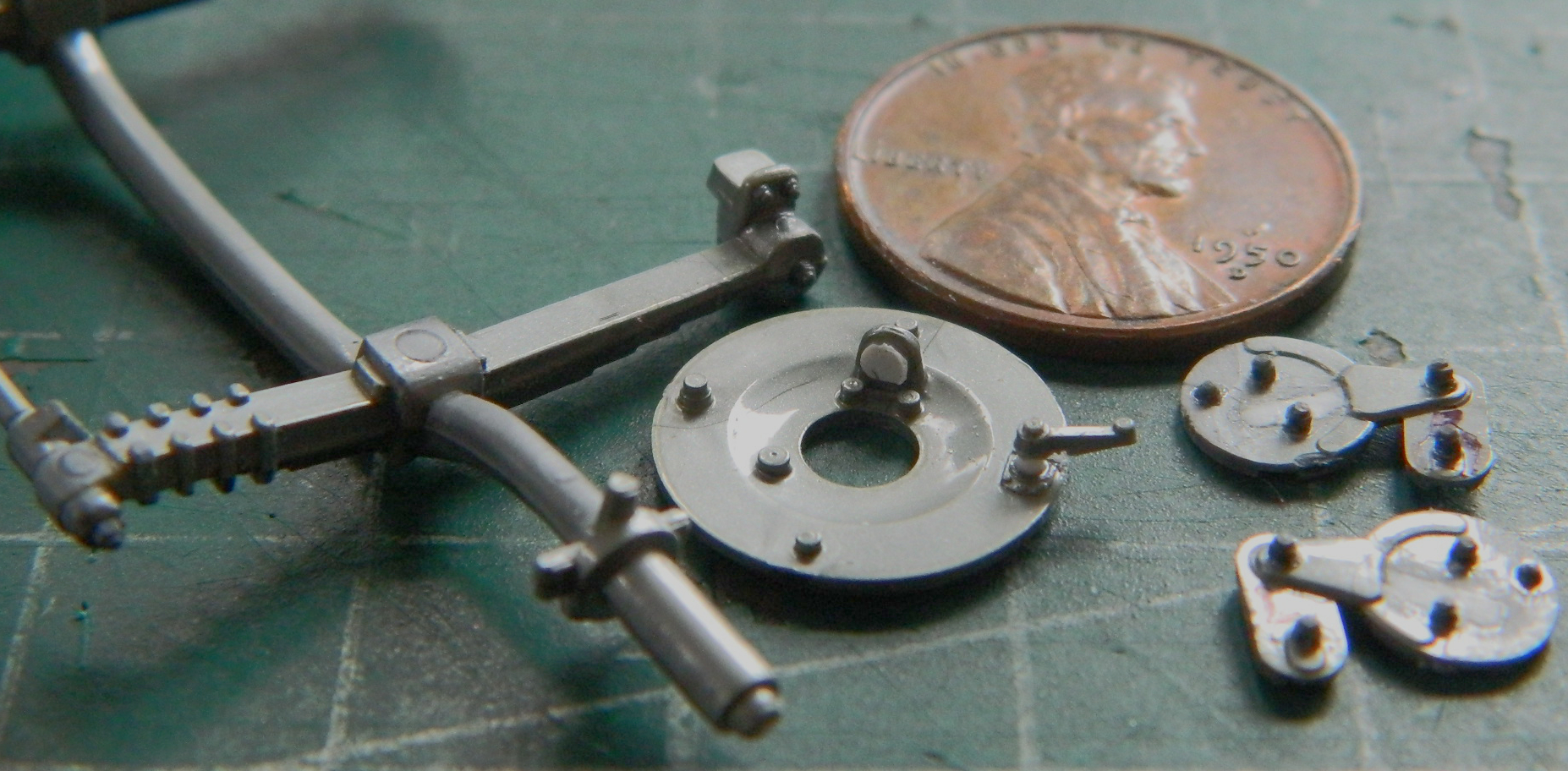
More Grandt Line bolt had to be added to the front axle where it mounts to the springs and where the spring brackets mount to the frame. I also added bolts to what I assume are the oscillation dampers (mistakenly called “shock absorbers” in the US…the springs absorb the shocks) which also needed large slots in them filled (I also punched out a small disk from .010″ (.254mm) styrene to replicate the pulley used with the brake cable):
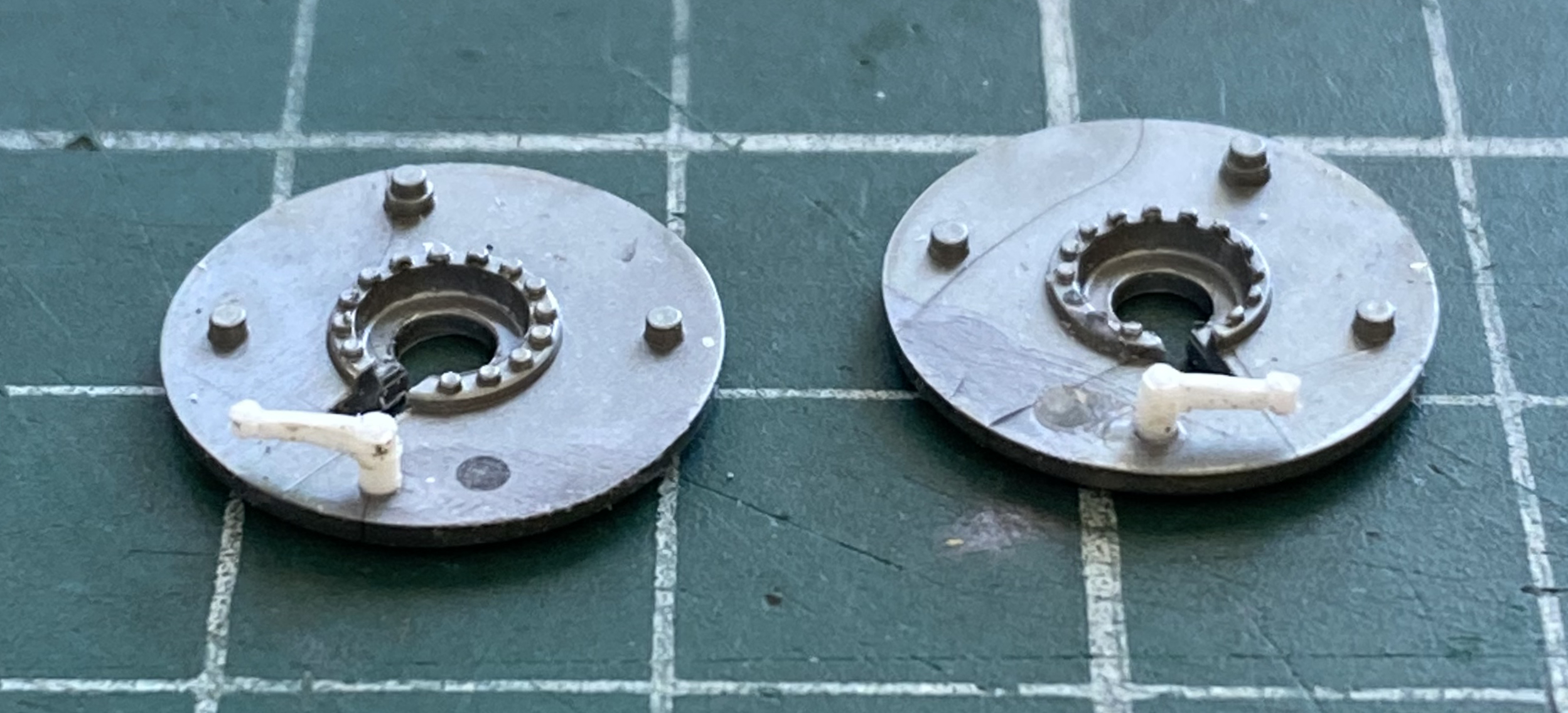
While I was thinking of brake cables, I built the levers for the rear brakes that the kit didn’t provide:
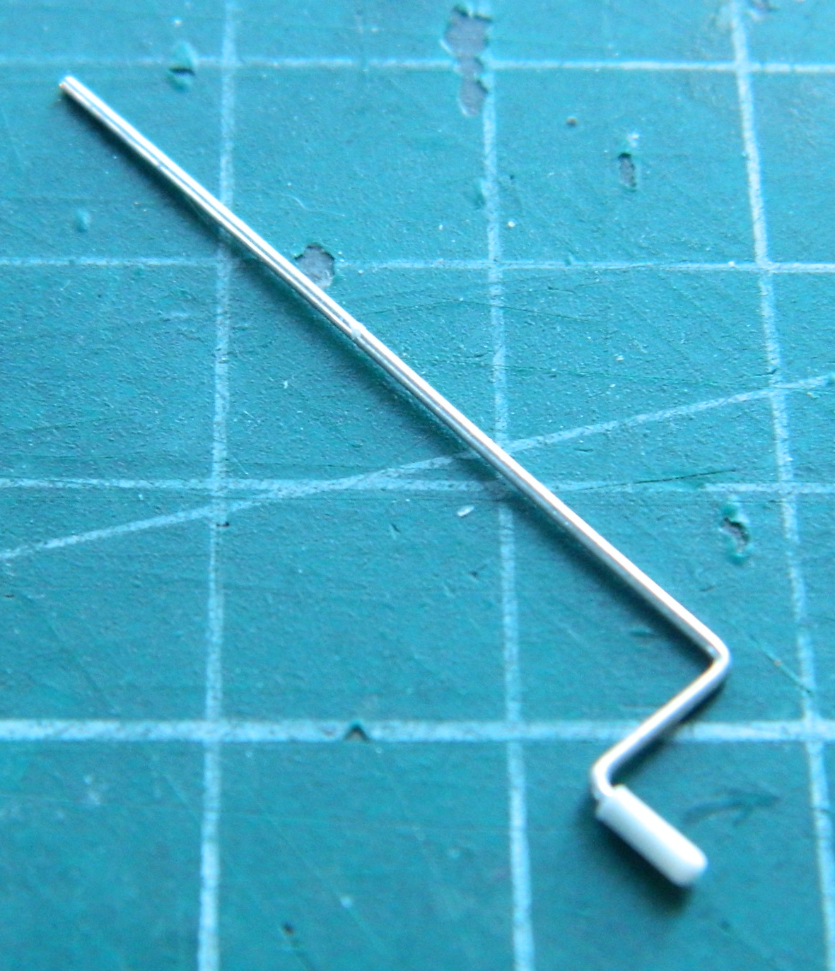
The starting crank was molded too thickly and in the wrong position. I cut it off and used 22 gauge wire and a drilled out piece of scrap styrene rod to make a replacement:
There were what I assume were cooling vents as part of the sump. I started drilling them out and realized that I’d used too large a drill bit so the holes needed to be filled:
The mounts for the windshield and the holes in the coaming were far too large. I started by filling the holes in the coaming (I’d also filled the mounting holes for the passenger’s windscreen):
The frames for the folding windscreens were inaccurate and out-of-scale. I annealed a piece of .010″ (.254mm) brass shim stock to drill, cut, and fold to make new mounting brackets for the frames that I trimmed (it turned out that the right brass bracket in the photo below wasn’t tall enough. I ended up using the left brass bracket and making a new on for that side):
The windscreen frame was drilled to accept .010″ (.254mm) wires that the brackets would mount to (none of my period reference photos show that the angle of the windscreen was set by using large wingnuts so I removed them):
It was worth the work:
Continuing work in the cockpit, I started making the clutch/brake pedal assembly as the kit’s part was wrong and out-of-scale. I started making the pivot shaft from a paper clip and the brackets for the clutch/brake pedal from drilled out styrene rods. The clutch pedal was made from .010″ (.254mm) shim stock and the brake pedal from .015″ (.381mm) scrap for the brake pedal arm and .010″ (.254mm) scrap for the brake pedal:

I thought I was just humming right along. I had to go out of town for a week and was looking forward to getting back to work. Got home, unpacked and did all the stuff one must do to get back to where one was before the trip, and then got to the work bench.
The first thing I did was this:
I broke the fornicating, sodomizing, tip off the OTHER frame rail! (See “Brain Fade” in “What the Hell Does That Mean?”)
Once I was done banging my head on the workbench, I aligned the broken part as EXACTLY as I could manage and then glued it. I’m going to go do something else today while the glue cures completely before I go back to it and see if the glue will actually hold this time (ask someone what the definition of insanity is…the answer is something of a cliche anymore) and, certainly expecting that it will not, I will make another frame rail.
::sighs again::

“I build my cars to go, not to stop.”
Don’t you have a story about a kid with a CRX that followed that philosophy?
LikeLike