Rather than thrash about the way I had been doing regarding the interior bits, I decided to structure events more logically and started with the front of the crew compartment. That starts with getting transmission parts ready to use:

Getting that part in the lower right of the above photo cut away from the pouring block and cleaned up was another exercise in trying to trim something with the consistency and structure of over-cooked spaghetti. (This is fun, right? This is why I do this stuff, right? Right?!)
Trimmed and cleaned up parts start getting added to the transmission body. Any modeler that’s reading this knows that another problem (not “issue,” because I’m not a publisher) we frequently, FREQUENTLY, have to deal with is a paucity of hands. We really need four instead of the stock-issued two. To get a couple of the tiny bits (lighter colored resin just about centered in the photo) showed me that I needed some way to keep them in place and apply superglue. Cue the Panavise! After (gently!) clamping the transmission body in the vise, I diddled and fiddled until I had the angle of the transmission such that gravity would hold the tiny bits in place long enough for a touch of superglue applied with the tip of a needle to set them properly in place:

The reason for the different colored parts was due to trying to add enough black dye to white resin to color it gray without adding too much and making them black (you’ll see those black parts later in this build). The dropper of the dye bottle doesn’t “drop” as much as it dribbles. I usually (in fact, almost always) mix resin in once ounce increments and the dye is VERY CONCENTRATED. Dribbles are not as precise as drops, resulting in varied coloration in the castings. The two levers at the rear of the transmission are the shifter (the long, lighter-colored part) and parking brake (the other one). The knob of the parking brake was not to my satisfaction so I used a tiny glass bead and replaced it:


[As an aside, I purchased this AM set in 2014 when I got back into modeling after 24 years. I was gobsmacked by the incredible detail provided. It wasn’t until about 20 minutes ago when I was editing the photos that I noticed the faint striations on the body of the transmission between the ribs. These parts were 3D printed! Given the state of 3D printers eight years ago, CMK did a great job producing these parts!]
On either side of the transmission are the seats for the driver and co-driver and I started with the co-driver’s seat. I used a 1″ (25.4mm) 90 degree angle to set the correct angle between the seat and seat back. Again, using gravity to keep parts aligned, I placed the angle and seat parts on an old resin cover to a welding mask and then elevated it just enough to align things while gluing:

The parallelogram base enabled the co-driver to ride with his head out (don’t go there) or drop him down into the hull so that closing the hatch didn’t result in a massive headache (and probably a concussion spiced with stitches). I assembled the base and then glued it to the seat bottom:

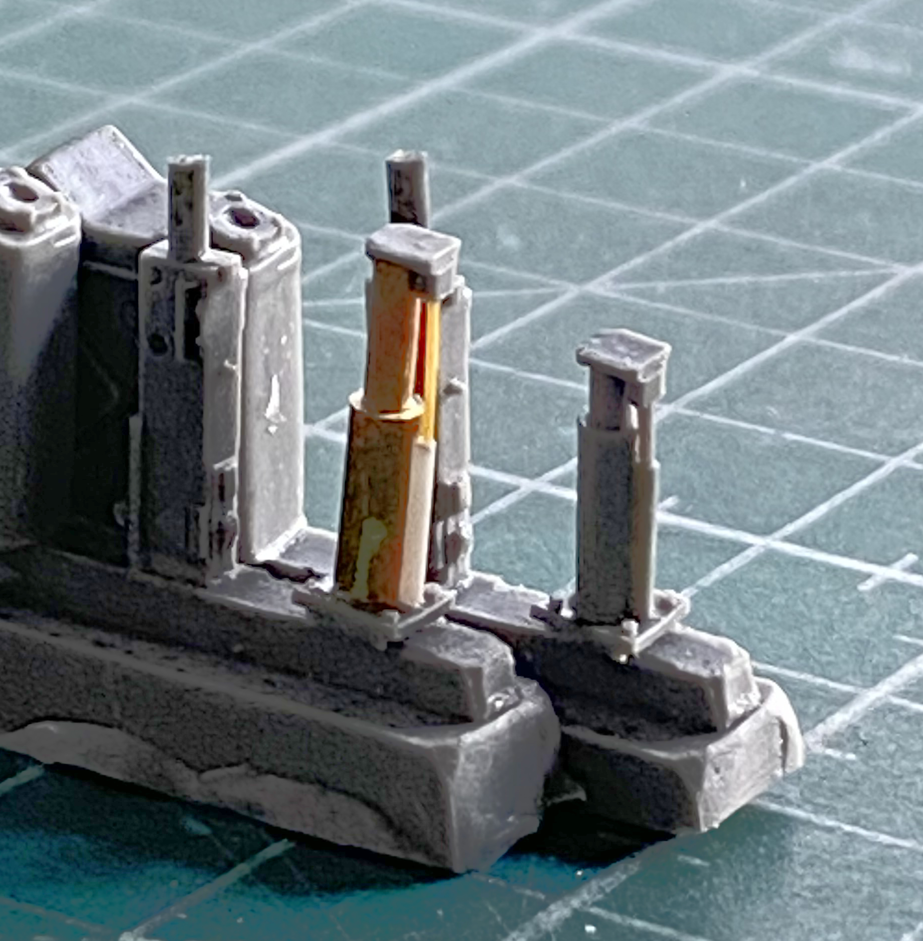
For whatever reason (craziness, perhaps?), I like altering the heights of these seats. The driver’s seat mount was utterly different from the co-driver’s seat mount. Instead of a parallelogram pedestal it was comprised of a telescoping column. That’s a lot easier to adjust than the height of a fragile and tiny parallelogram (#90 is the telescoping pedestal and the copper tubing and styrene rod made altering the height possible):

This is how far the seat was raised:
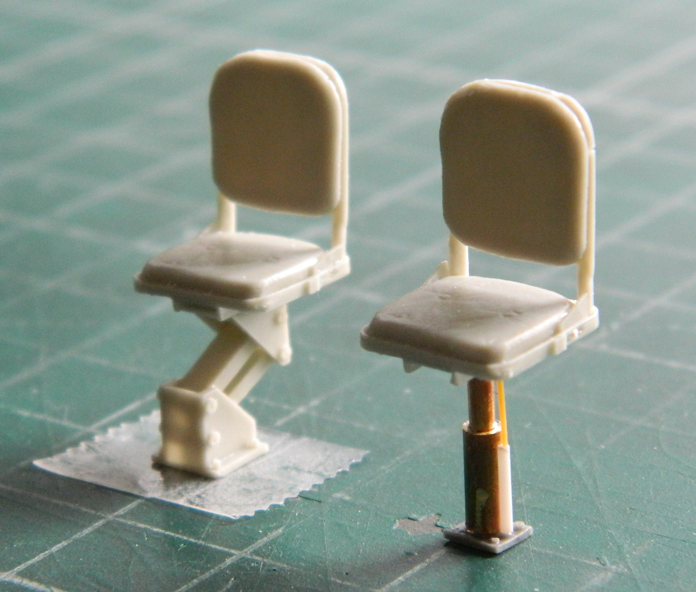
As you can (in a blurry sort of way), there really isn’t all that much difference between the height of the two. In comparing the as-provided height of the base and what I modified that height to be indicates that the co-driver’s seat was actually supposed to be (according the manufacturer) higher:
Well…so much for that.
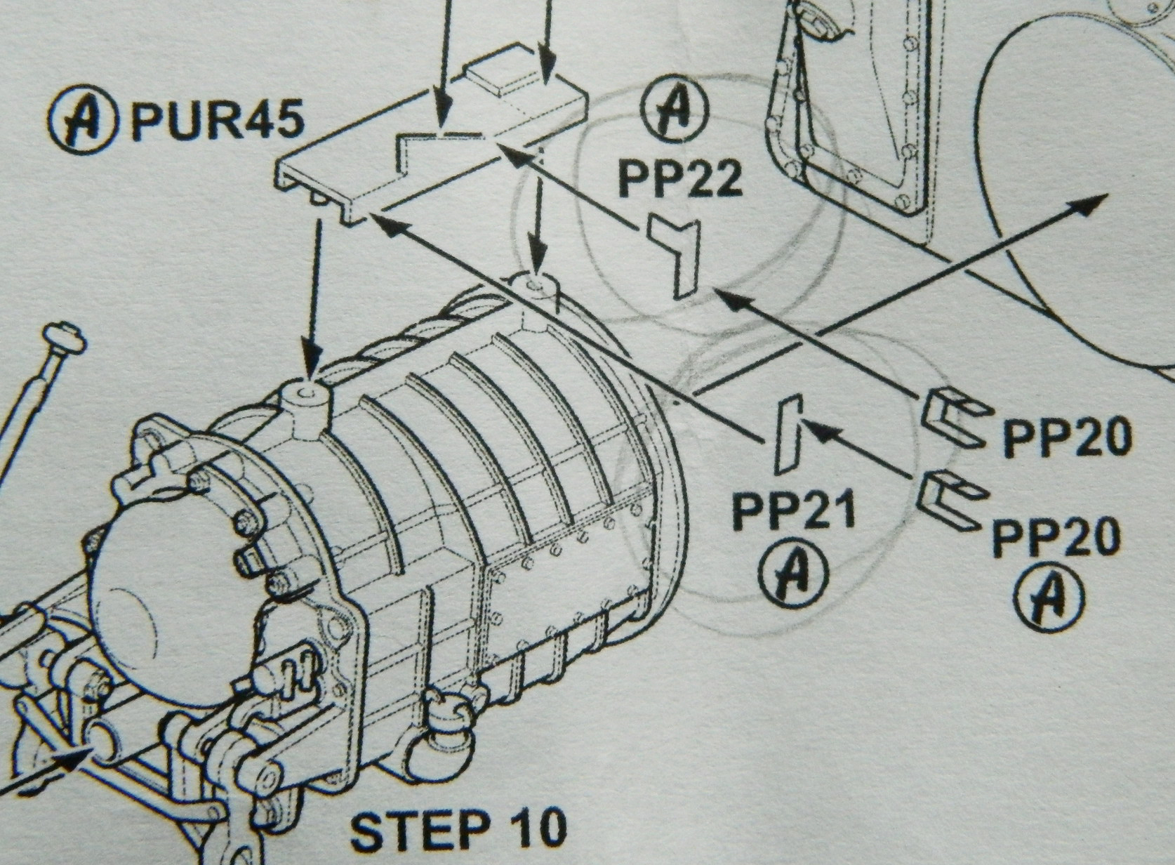
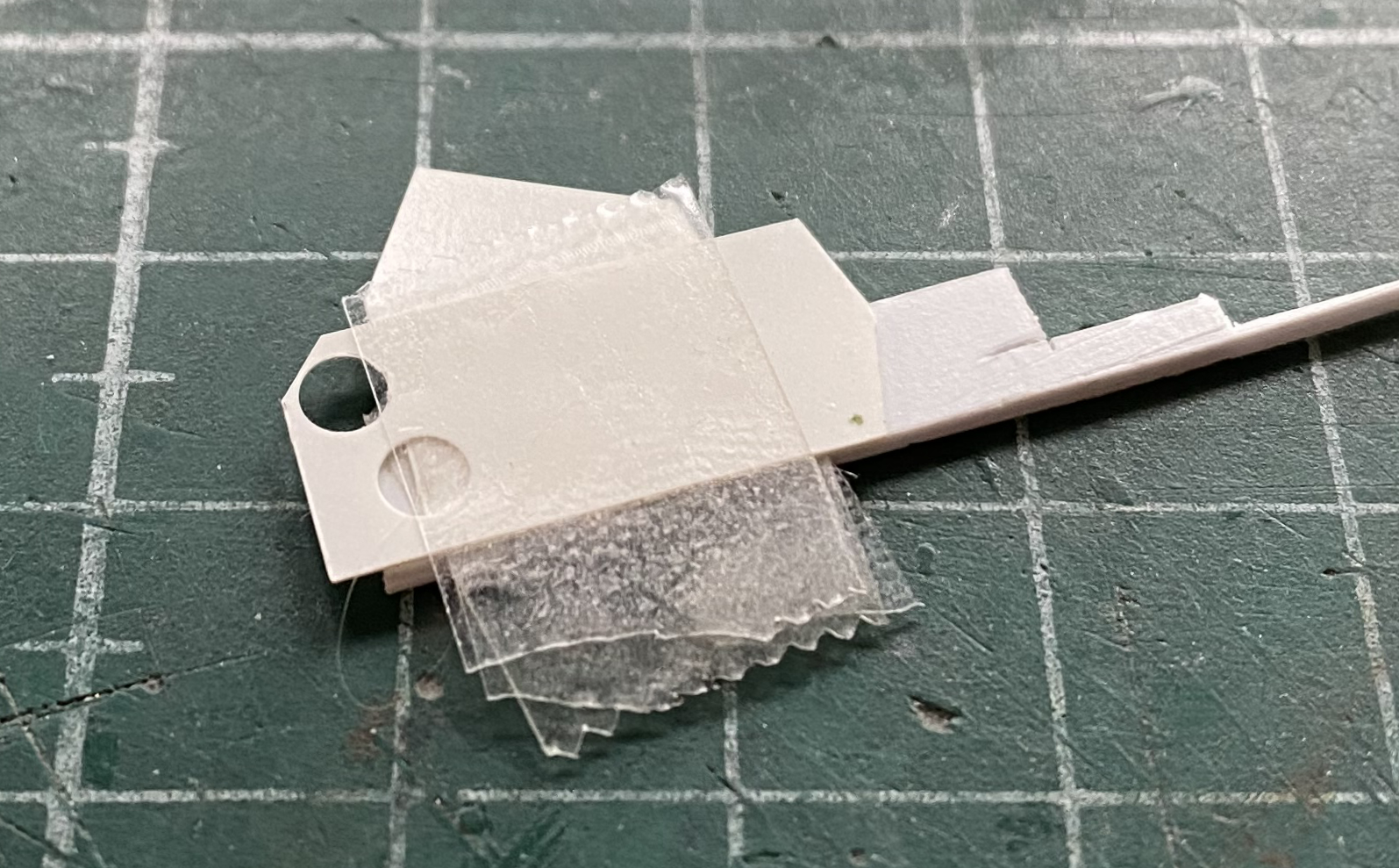
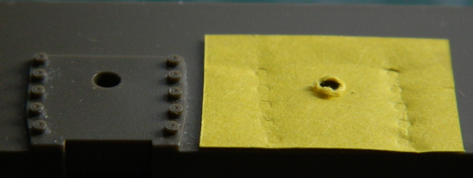
I went back to the transmission and copied some small PE parts using .005″ (.127mm). Simple parts, easy copy, but then I looked at the directions to see where they go. What I found was something a bit less than specific (the parts involved are circled):
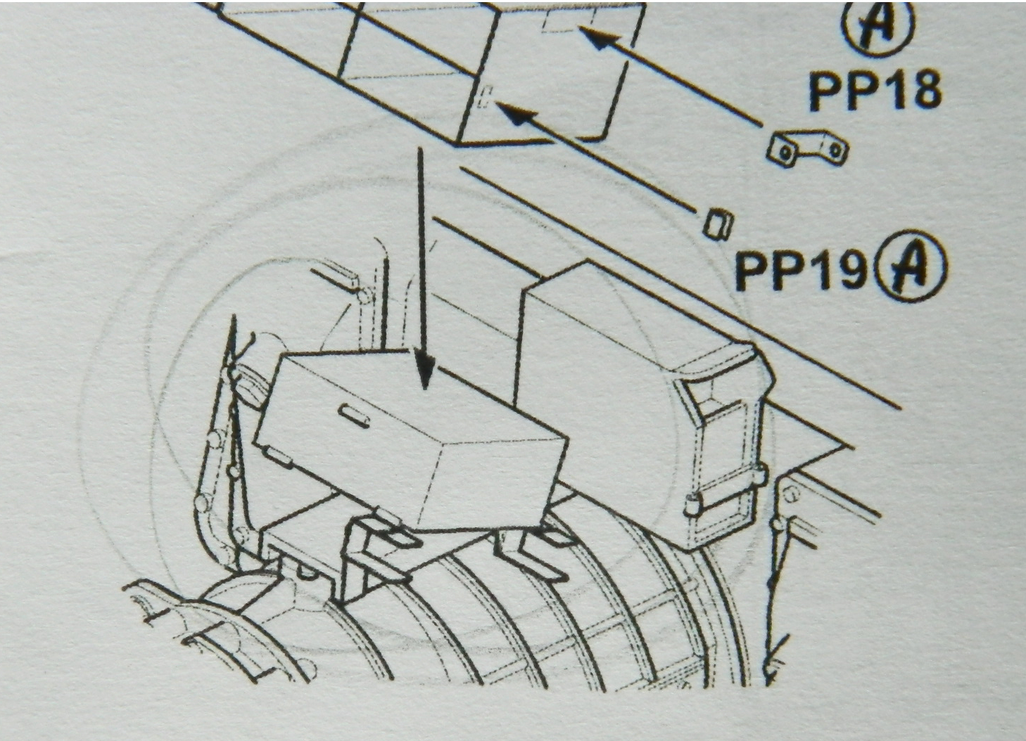
And while I was dealing with that little puzzle, I cut part PUR45, which is the platform the box mounts onto, from the pouring block. Did I mention warm hands and flexible-when-warm resin?:

Yeah. That was fixed:
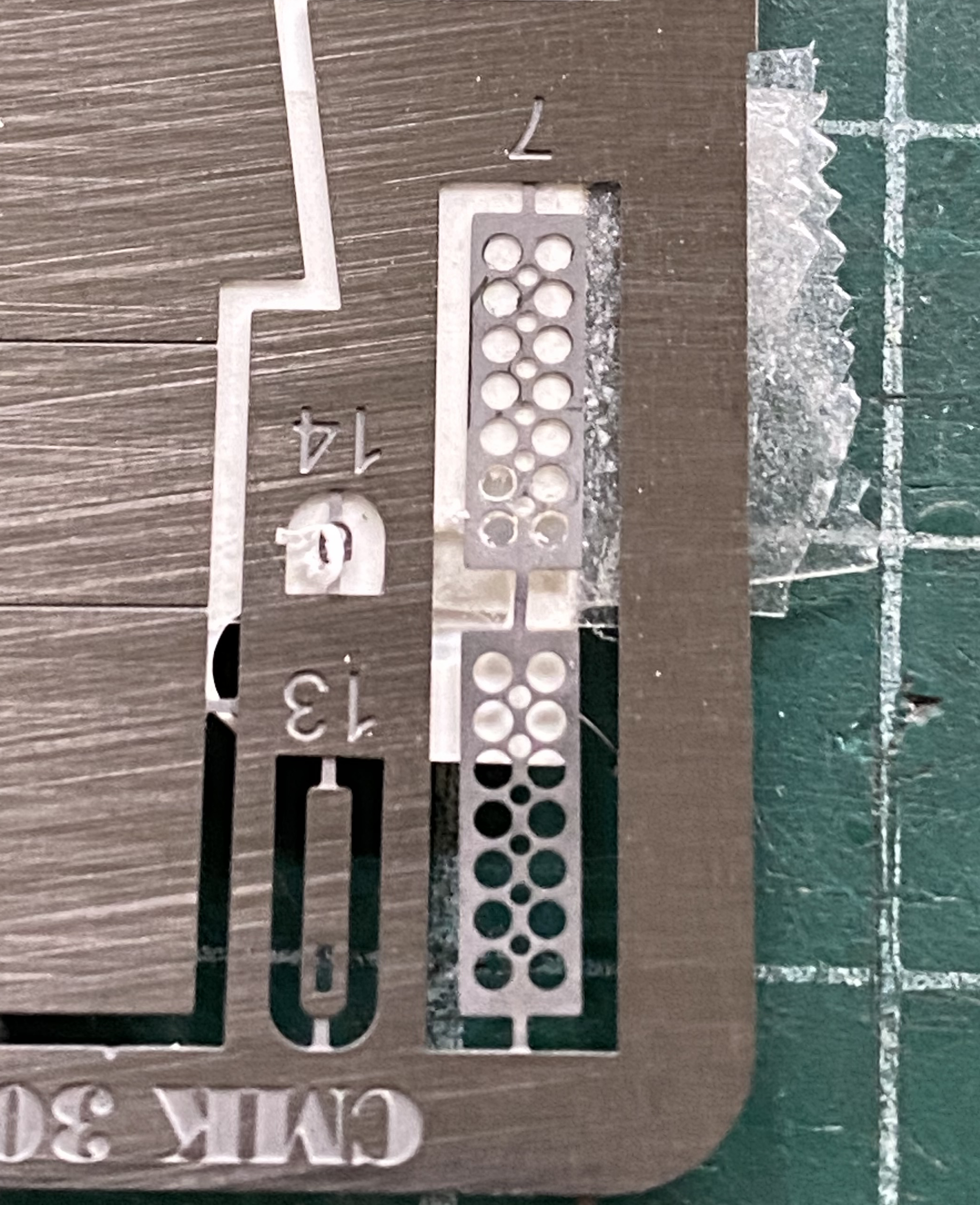
So far the instructions have been fairly decent. I decided to check later steps to see if perhaps there was an actual indication regarding the location of these small bits…and there is:
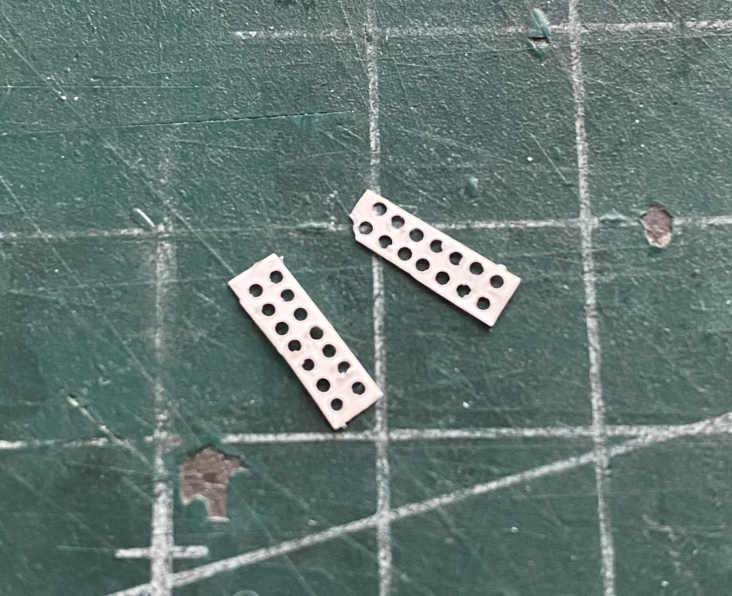
They were glued on and events proceeded with a flattened mounting plate (and yes…I know the partition’s sections aren’t square…that was fixed later):

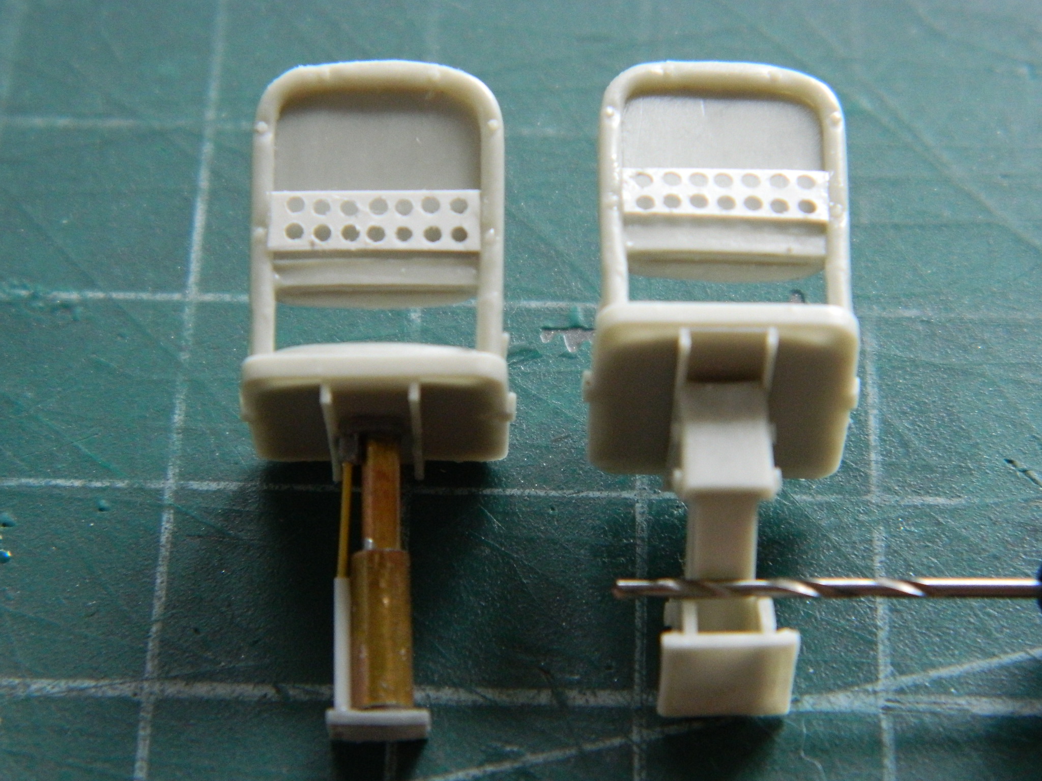
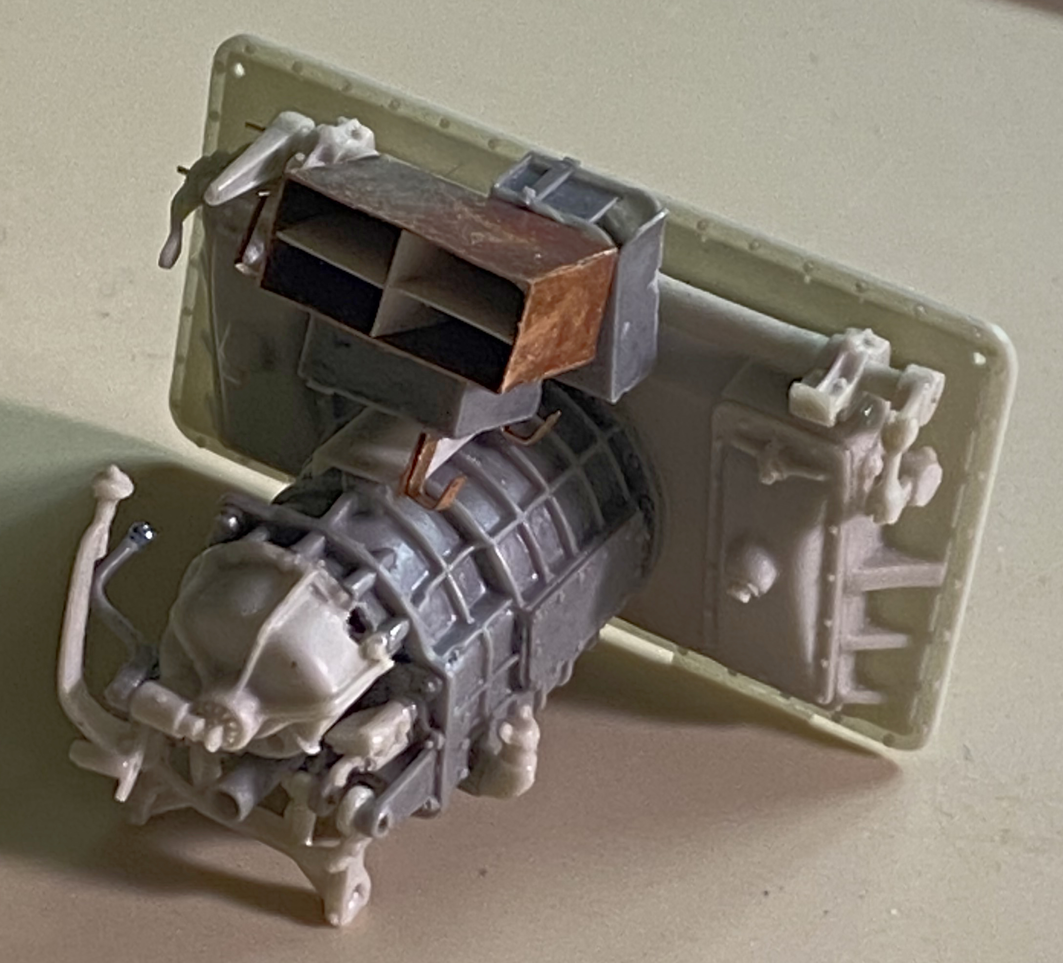
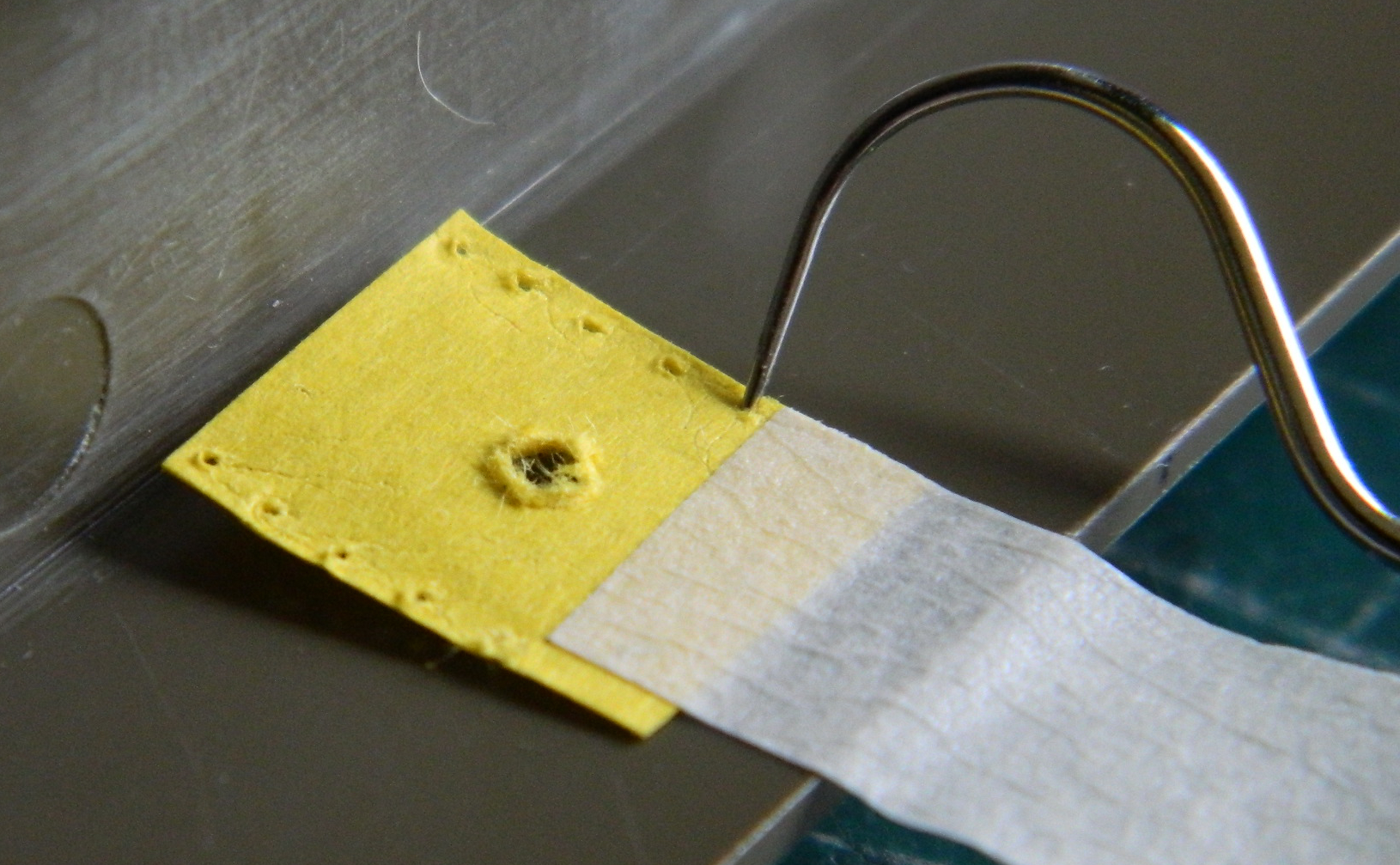
One of the tasks that was hanging heavily over my head was the reinforcements that were part of the seats’ backs. The AM set offered PE parts, but why do that at this point? Instead I figured out a way to do them in .005″ (.127mm) styrene. I had made the box itself from copper shim stock because that part has structural requirements (albeit slight). Rather than do the partitions in copper, I used styrene. But look at all these holes I have to drill:
Yeah…just try to get 28 holes that perfectly aligned. Pity that I couldn’t use the PE parts as guides…oh. Wait. I can! Drilling, however, tends to elongate holes in thin material as well as create all kinds of feathering on the reverse side of the hole being drilled. I minimized that by making a sandwich (or more accurately, a temporary laminate). The drilling backing was a scrap piece of .040″ (1.016mm) styrene onto which I stuck a piece of double-sided tape, then the .005″ (.127mm) styrene I wanted the parts to be, another piece of double-sided tape, and then a piece of .020″ (.508mm) styrene on top of it all. Then I used the PE parts as my drilling jig (I didn’t drill out the tiny holes because evidently even my nit-picking insanity has limits) (who knew?):
The downside to doing all that was the fact that I’d slightly misaligned the .005″ (.127mm) plastic and didn’t notice that a corner was missing:
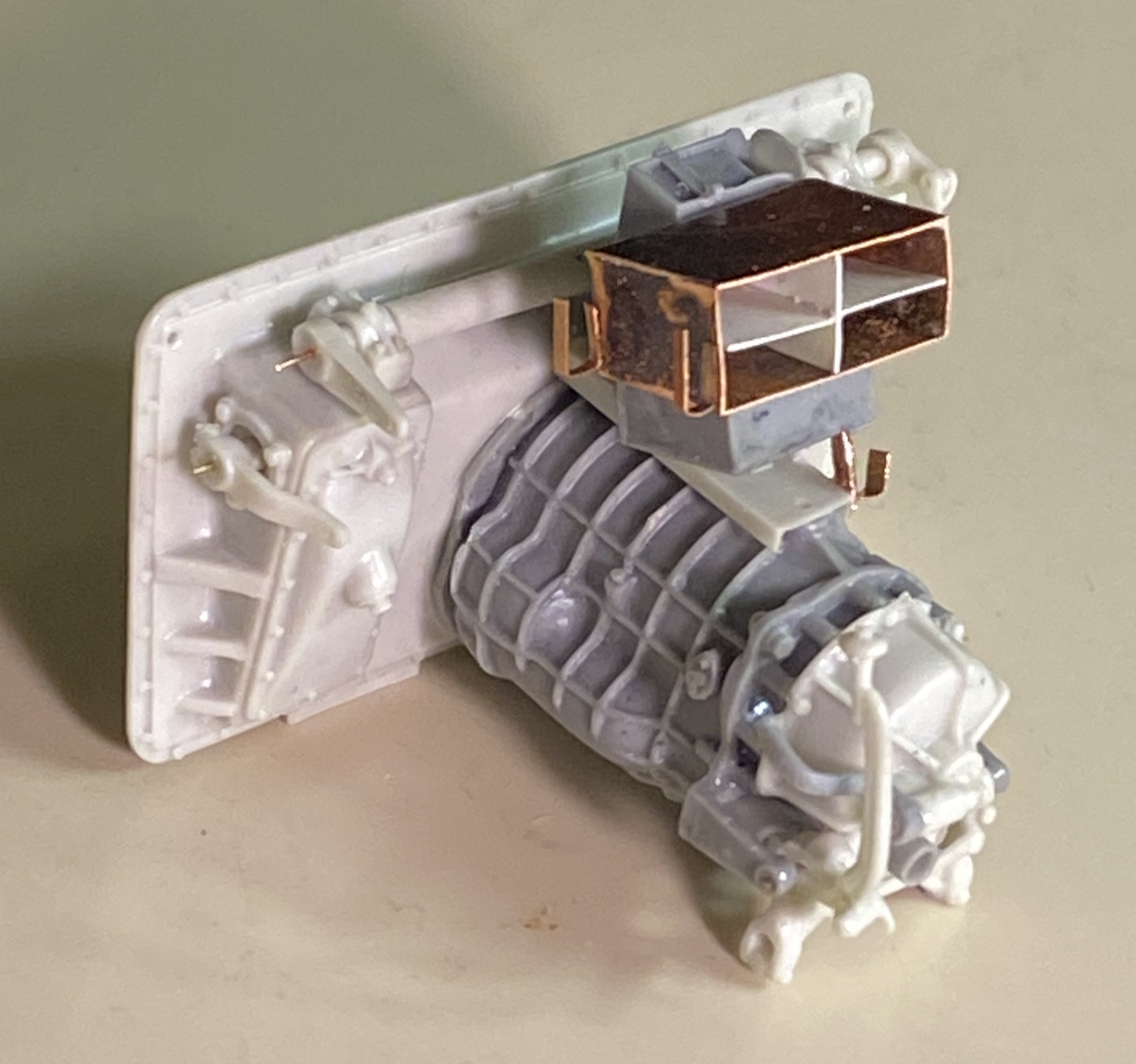
As you can see in the above photo, even by laminating the plastic, I still ended up with feathers or blow-out on the reverse side. While grumping about having to redo one of them, I stuck the piece that wasn’t missing its corner to double-sided tape and used a fresh single-edge razor blade to cut the feathering away. And then I had the notion that I probably could add styrene to the missing corner while that part was on the tape. So I did and it worked:
Even though my shop has no carpet that would morph into the dreaded Carpet Monster, small parts are SMALL. Many hours are spent per build crawling around looking for what the “tick” of my tweezers have told me has departed. And when I go looking for the part, I go looking for the part…up to and including moving EVERYthing:
Sometimes I even find the missing part (and as of this post, I’m adding to the After Action Report how much time during the build I’ve spent crawling around looking for things).
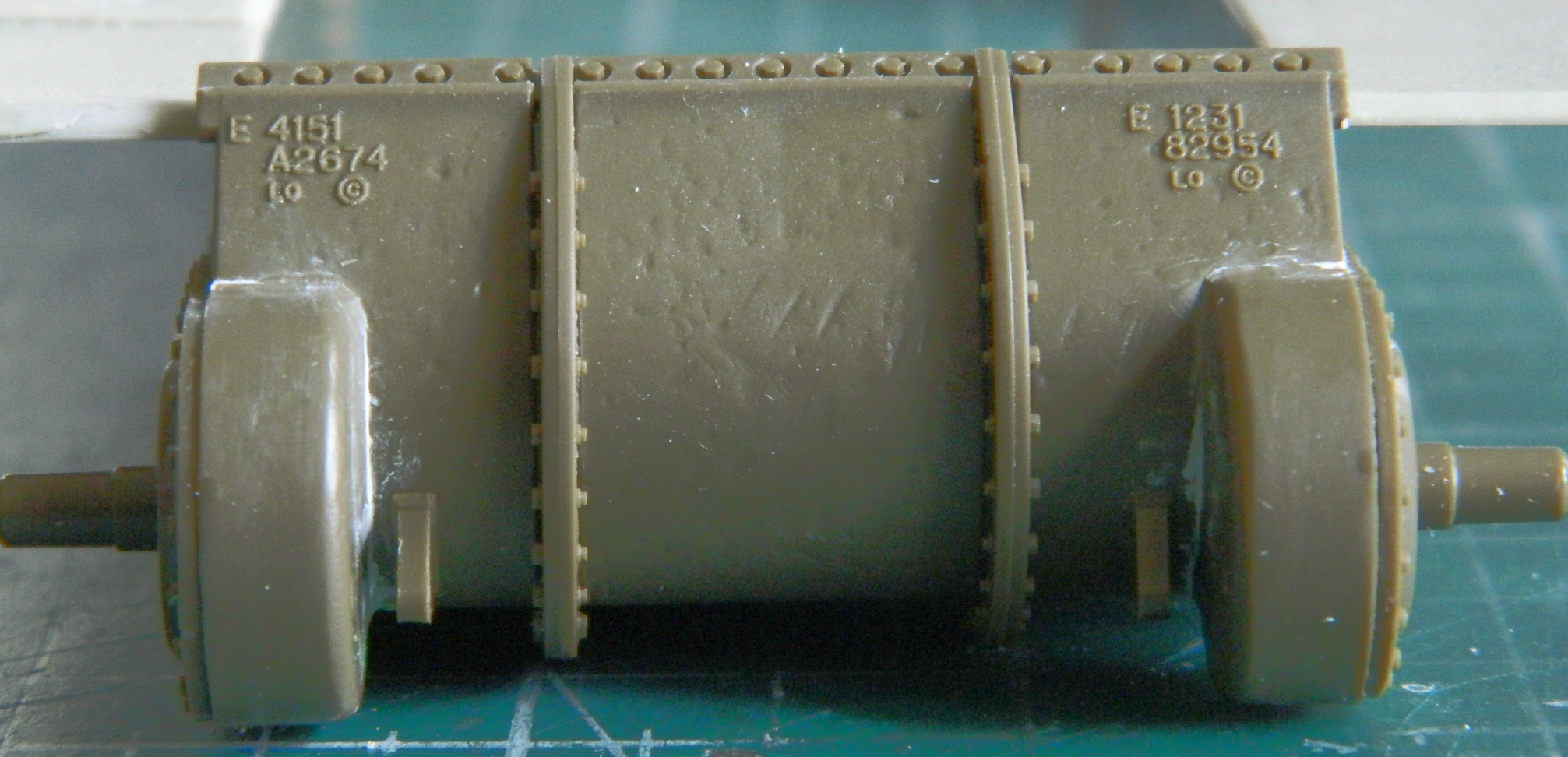
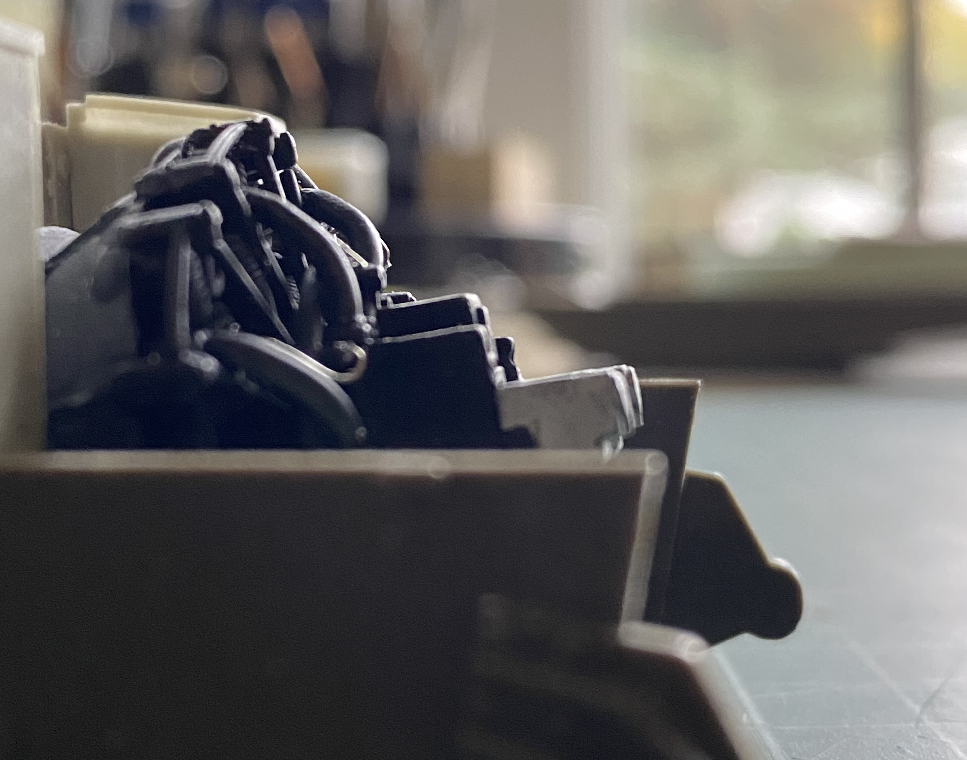
With the transmission mostly built and the glue totally cured, it was time to add the transmission to the back of the differential housing. That started with attaching the cross-tube for the steering brakes. Because there are very small levers attached to it, I drilled out every place a pin had to go and added pins (lessens the amount of hand required to assemble things down to the mere two I was issued):
Then the painstaking job of getting the transmission correctly aligned began. In the photo above, please note that there are no locator marks other than the easy-to-overlook flat spot at the bottom of where the transmission mounts to the differential case:
The mounting bulkhead for this subassembly was cast separately (not my idea…) so that had to be added. Once again, the part wasn’t quite large enough. So I clamped and glued it to the best of my (limited) ability:

When Tamiya cut the dies for this model, they had mistakenly added “cast texture” to sections of the multipart glacis. And while looking for something entirely different (casting marks of the many different subcontractors who made various parts), I noticed that the Sherman hull that Tamiya copied is an ALCO (American Locomotive) hull. When you look at the mount on the glacis where the bow machine gun goes, you will (or should, anyway) notice that the bulge isn’t circular overall. There are straight sides and a rounded top. This shows that this hull is an ALCO hull. The same diagram that showed the ALCO hull also showed how the different plates were welded together. Most of the glacis is rolled (aka flat) plate with just the crew hoods (the bulges around the front of the hatches) and bow machine gun plate being cast…and of course Tamiya had everything on the glacis with that cast texture. Oh. And they got some of the plates incorrectly as well. I used Dymo label tape as my straight edge and scribed the correct panel lines and filled the incorrect seam between the hoods, marking the rolled armor with an “F” (because I’m easily confused, as you can tell by the fact that after laying down the lines I still had to scribe them instead of using the tape as my scribing guide):
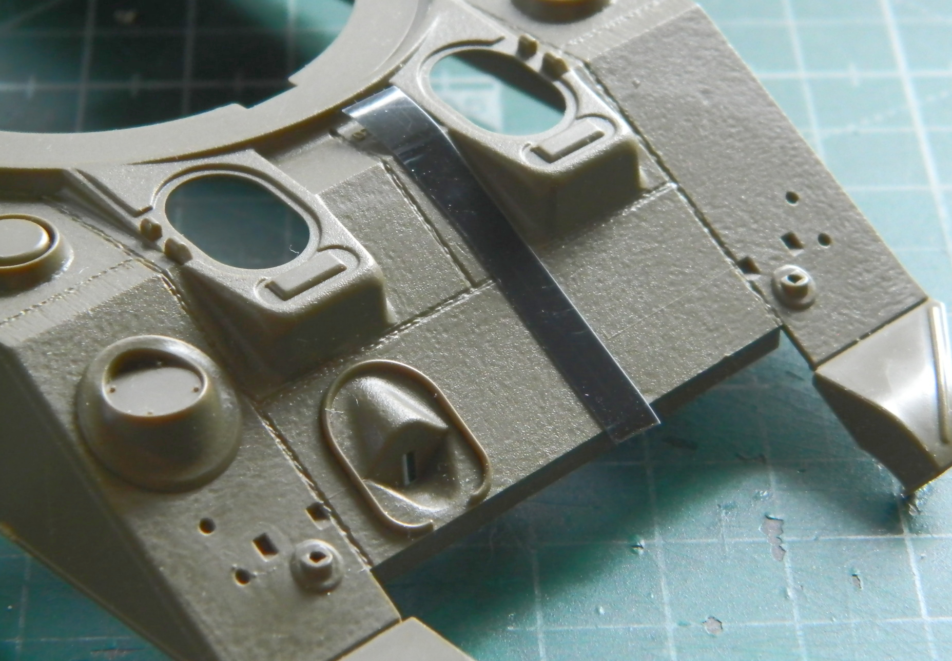
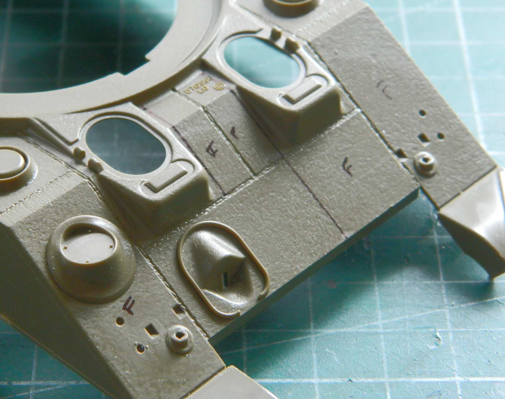
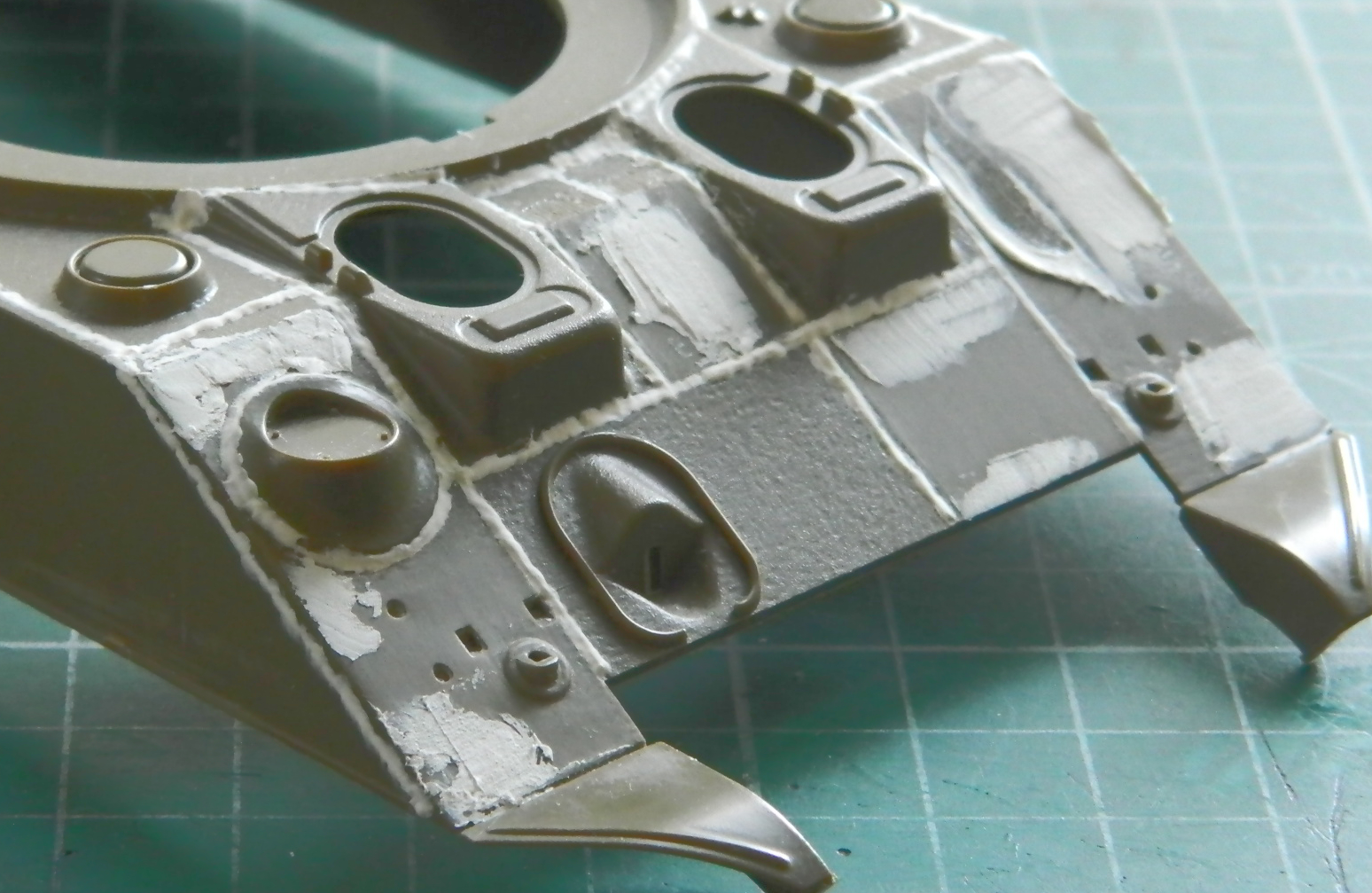
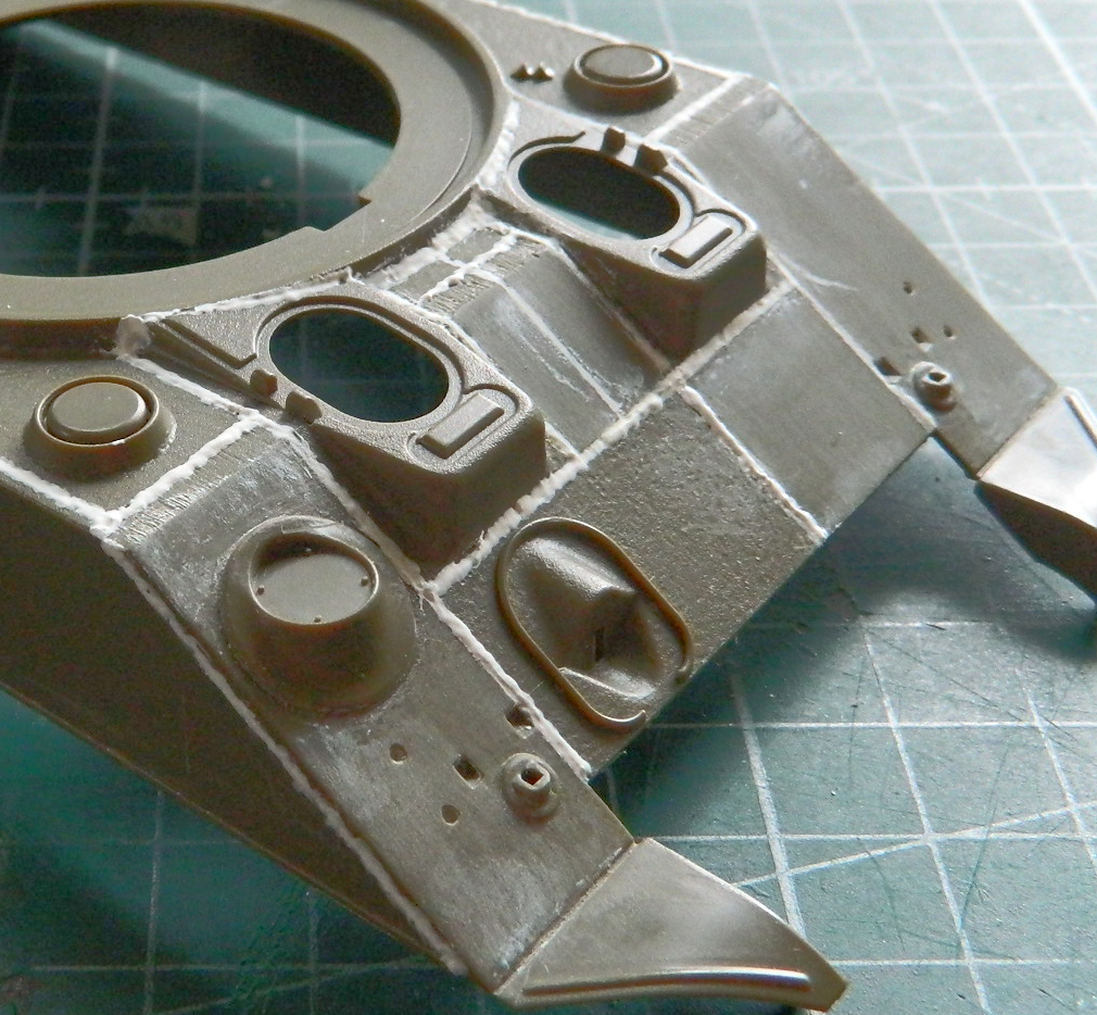
I used Vallejo acrylic putty (#70.401) to fill in the weld lines…all of them all over the upper hull, then I started sanding away the cast texture and used 3M acrylic putty to fill in the really deep areas of texture:
Dry-fitting the transmission assembly and driver’s floor showed me that I had the steering levers, shifter, and parking brake handles slightly out of position. Here’s where having resin that is flexible when warm came in handy. I used a hairdrier (LOW SETTING!) to make things flexible and coaxed them into their corrected positions:

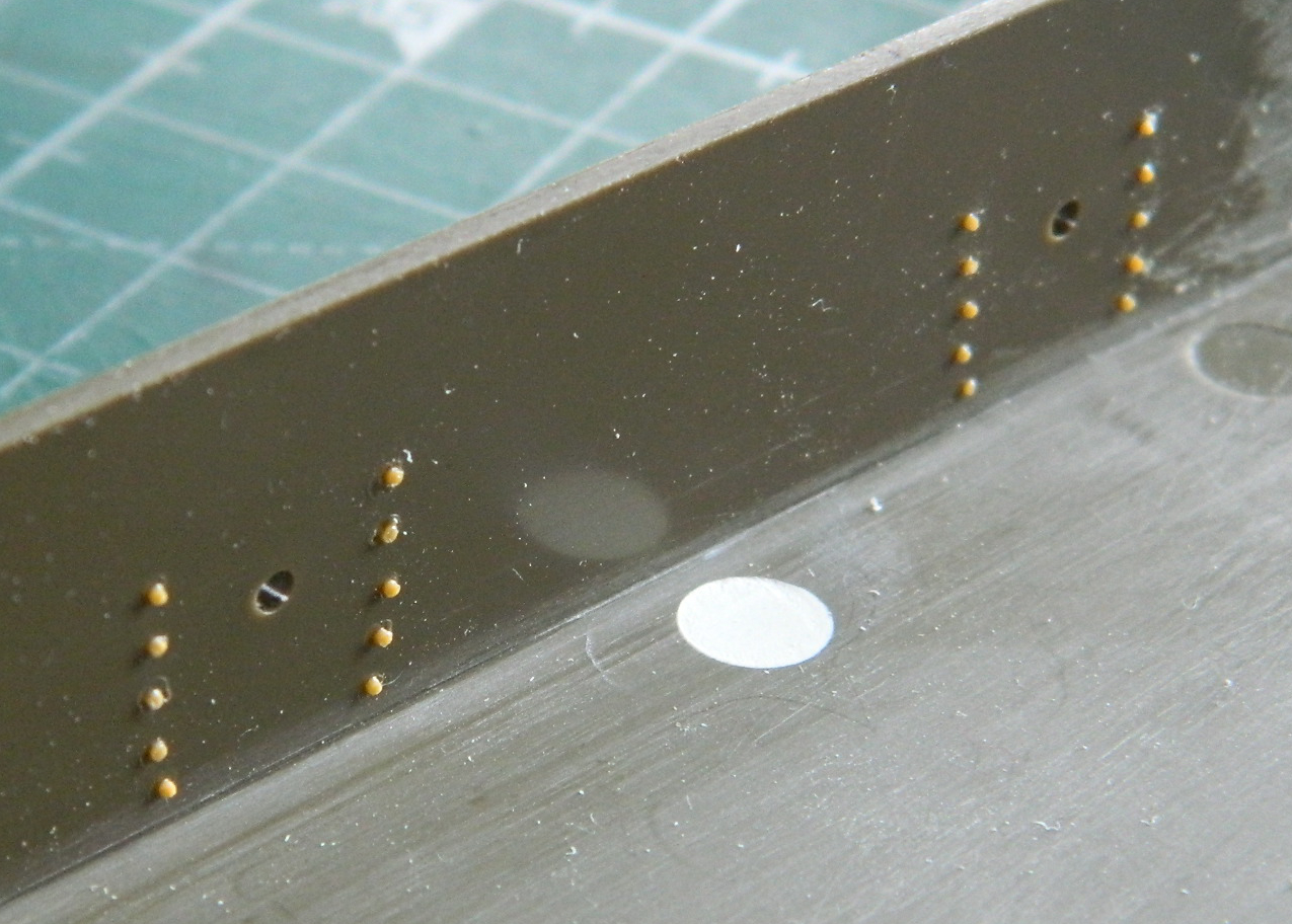
Back inside the hull, I wanted to replicate where the bolts that hold the suspension bogeys in place protrude into the interior. That started by making a pattern of the bolt pattern and location with Post-It Note paper using the locating hole for the kit’s bogeys for alignment:
Then they were aligned inside the hull and marks poked through the paper into the plastic:

None of the Grandt Line bolts I have are the correct size so I scraped sprue into an octagonal cross section and then stretched it:
Then the sprue was salami-sliced (why salami? Why not bologna, turkey, or roast beef?) and the “bolt” heads glued over the depressions poked through the paper (the bolts to the right in the photo are in the engine bay and will be covered by the fuel tanks so I’ll shave those off):
When these tanks were upgraded to increase crew protection, it had already been determined that the vertical faces of the crew hoods were susceptible to penetrating shots (like the rest of the Sherman’s armor wasn’t?!). Flat armor plates were welded in front of the hoods at an angle that was assumed would offer better penetration resistance (snicker). Tamiya also molded these add-on armor plates with cast texture so that had to go. Rather than sand them down, because being easily seen in position would probably make them noticeably thinner, I used double-sided tape to hold them while I used a skim coat of 3M’s putty to fill in the texture, sanded them flat, and then glued them in place on the glacis:

There are easily seen weld beads where the tops of the armor plates welded to the hood. Later I will use the Vallejo putty to replicate those.
Before I started hanging more bits from the lower hull, I added the tow hook mounts:
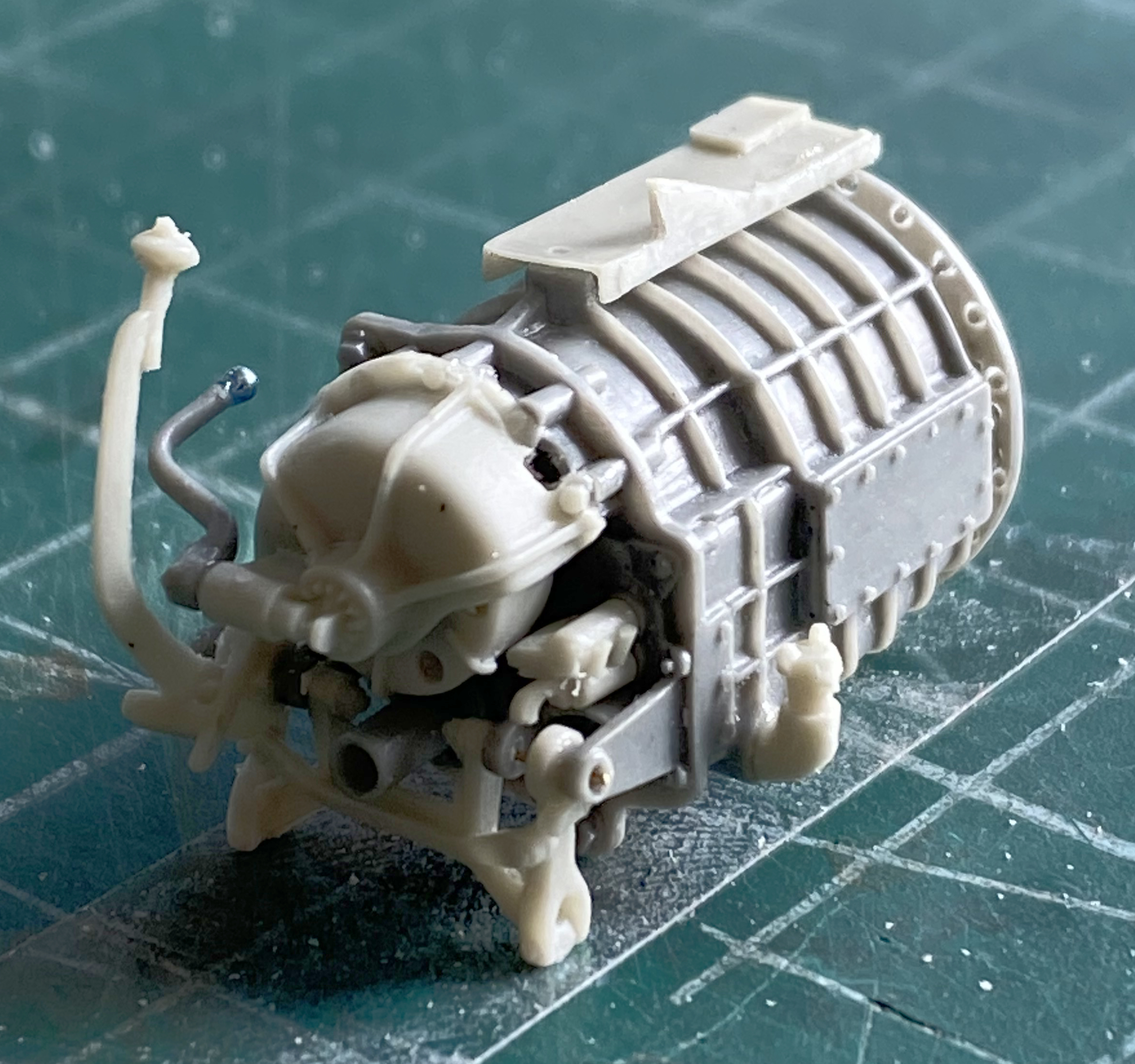
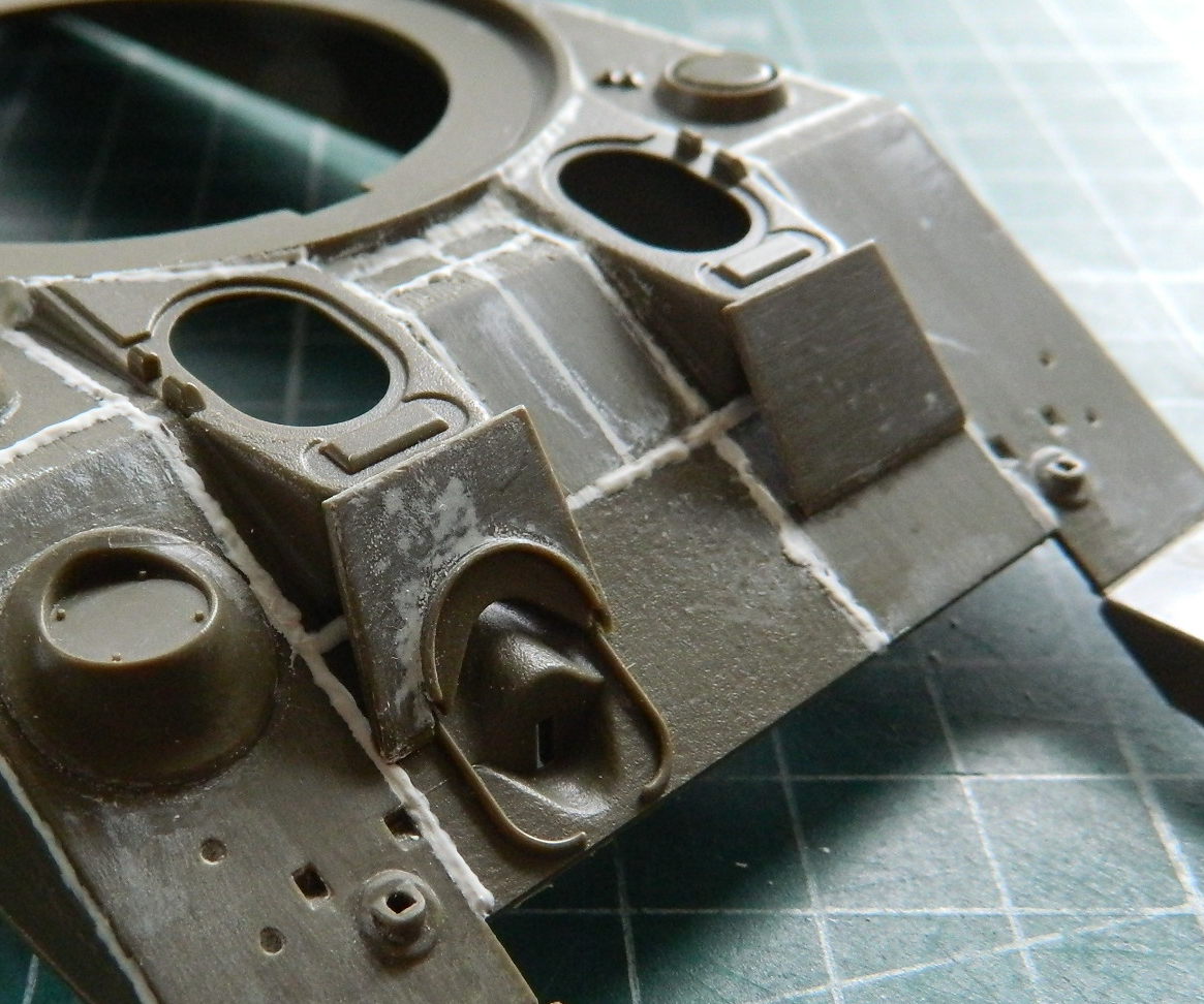
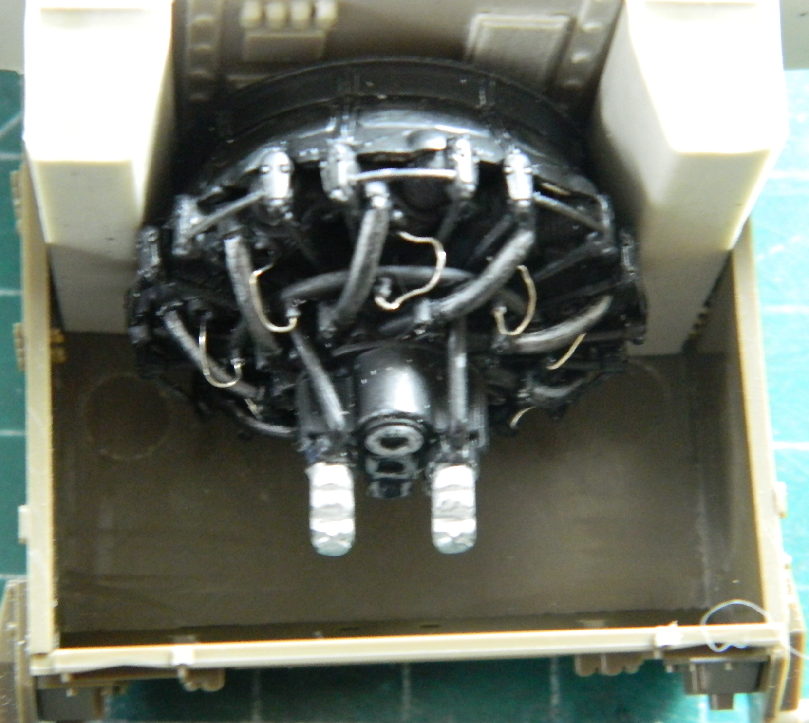
At this point I wanted to dry-fit the interior assemblies and check the engine for fit. Good thing I did because I found that it did not. I needed more room at the rear of the engine.
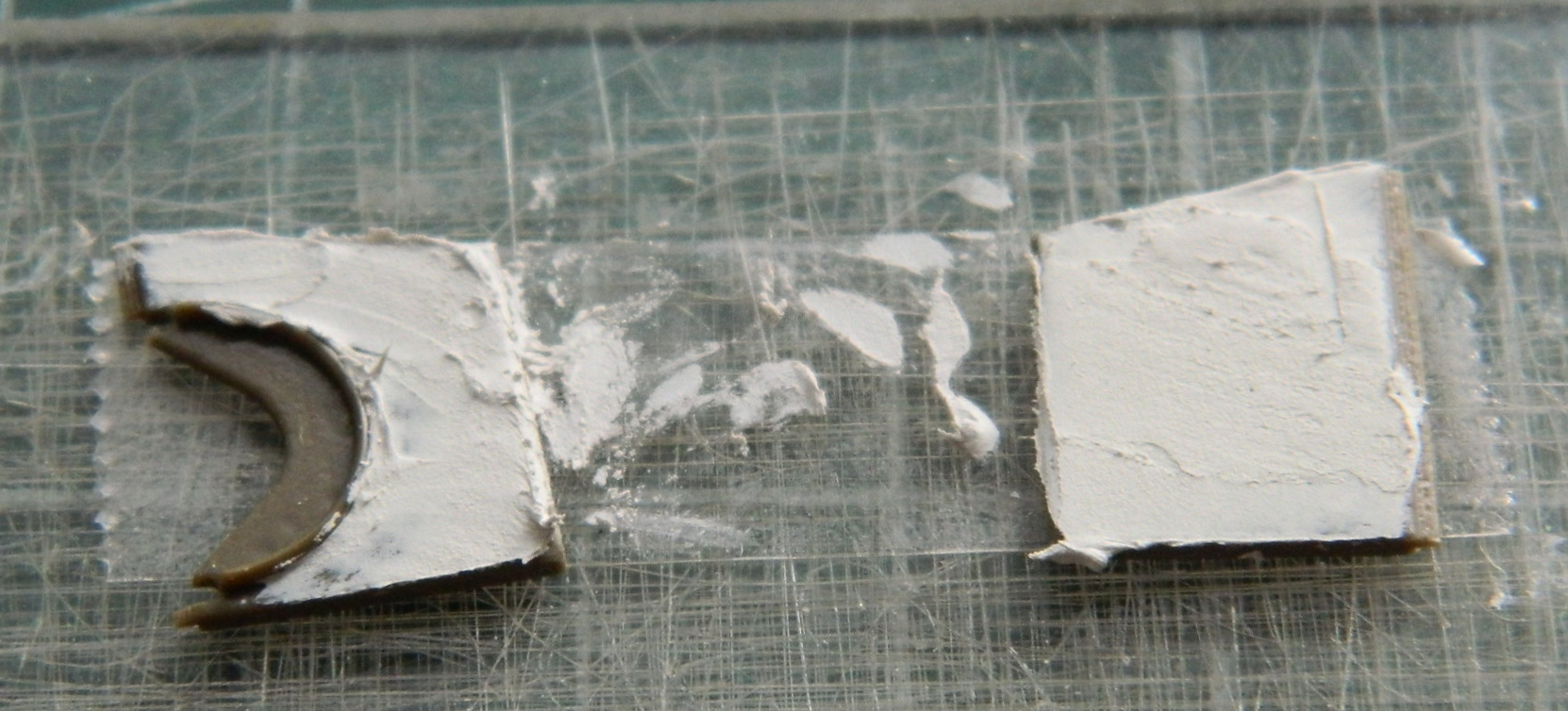
And while I’m touching on that subject, a word about mixing AM sets. CMK made the interior set and that includes the firewall. TWS made the interior set for the engine bay that also includes a firewall. Roughly speaking, that means I had (yes…past tense) double the thickness with the firewall. Tedium ensued as I filed, sanded, ground, curse, whined and whimpered each firewall to about half its original thickness. If each part is half its thickness, that means I have two parts that combined have a single thickness. Easy notion. HOURS of work followed…and remember, thin sections of resin don’t hold up dimensionally to warm hands. It was like trying to sand a latex glove at times. But of all the things I’m good at (both of them), giving up isn’t one of them. I got them thin, flat, and taped together before I tried dry-fitting (you can see the two parts taped together). And I still needed more room:
I know it looks like I have just enough room, but I don’t. The engine still has space-filling bits that hang off the back of it. I still need more room.
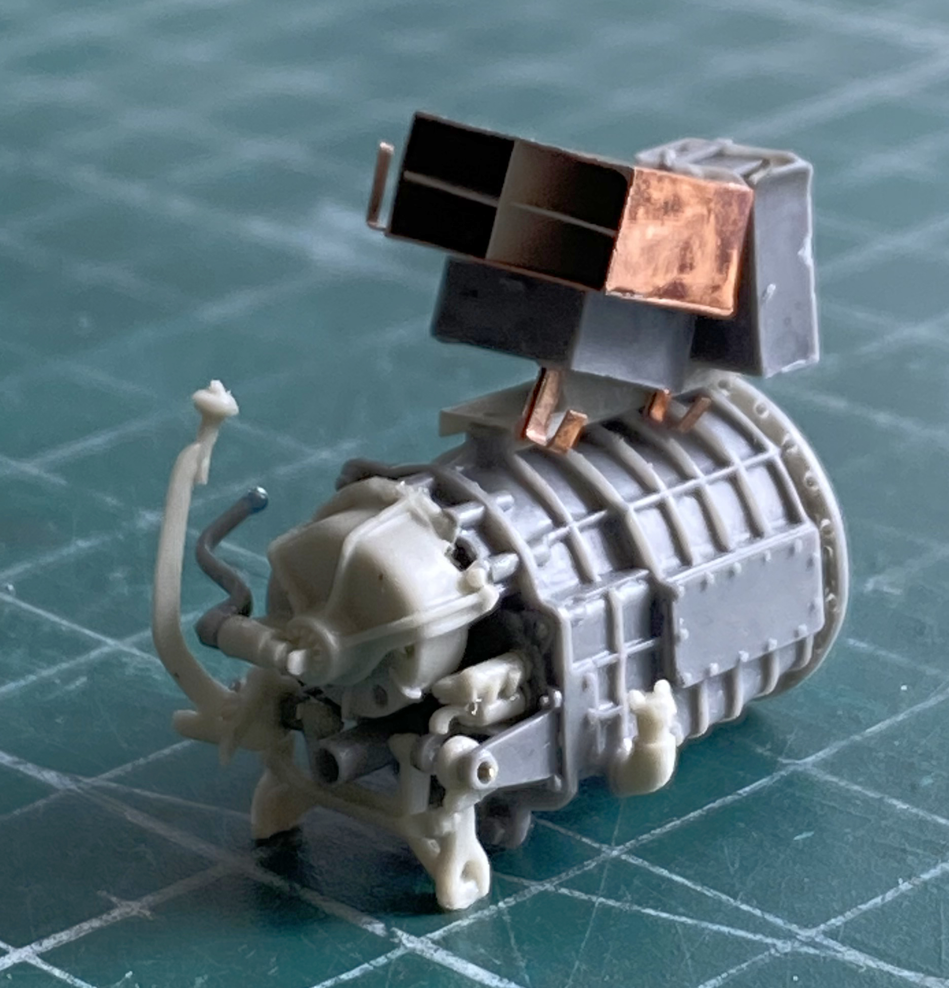
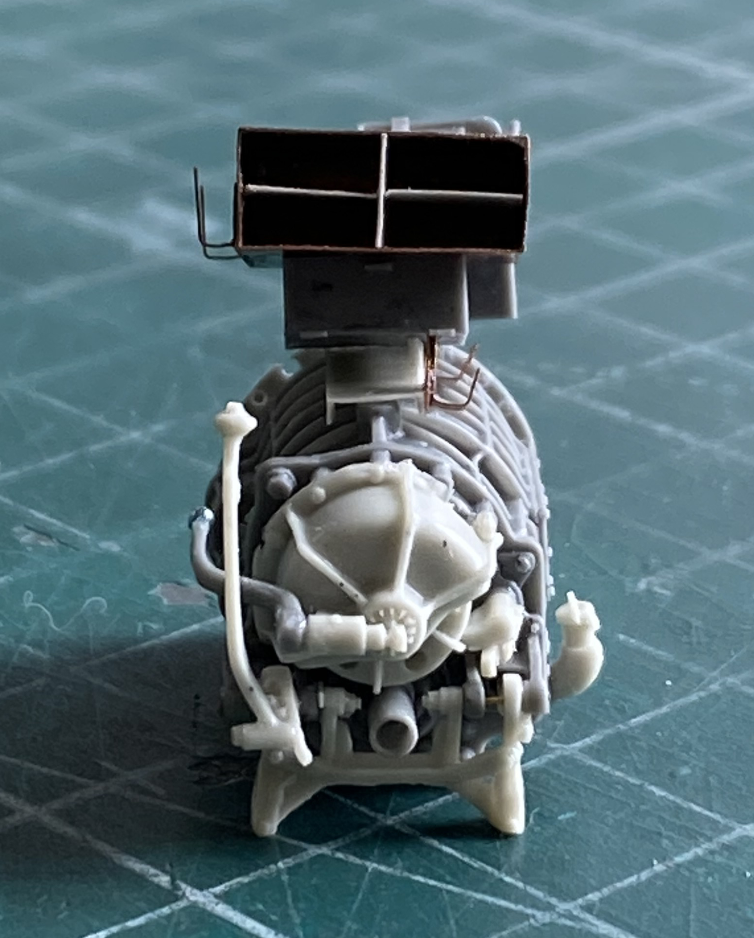
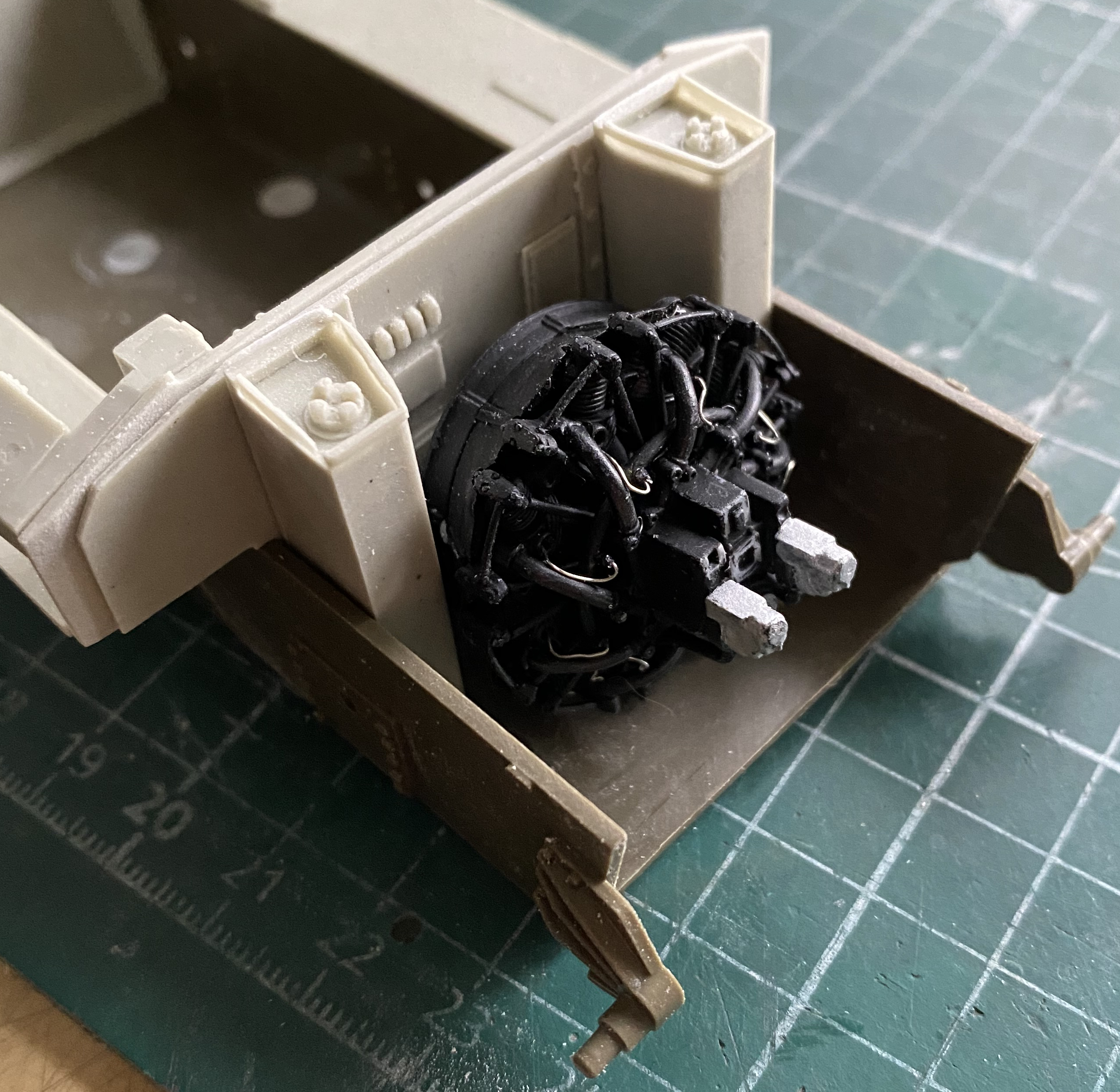
If you look at post #1, you will see a part sticking out of the front of the engine. This is the throwout bearing and driveshaft mount. Well, even on the actual tank, that bearing/shaft assembly is inside the firewall and will never be seen. I cut that piece flush with the engine and it worked…I have JUST enough room (I think…subsequent dry-fittings will tell):
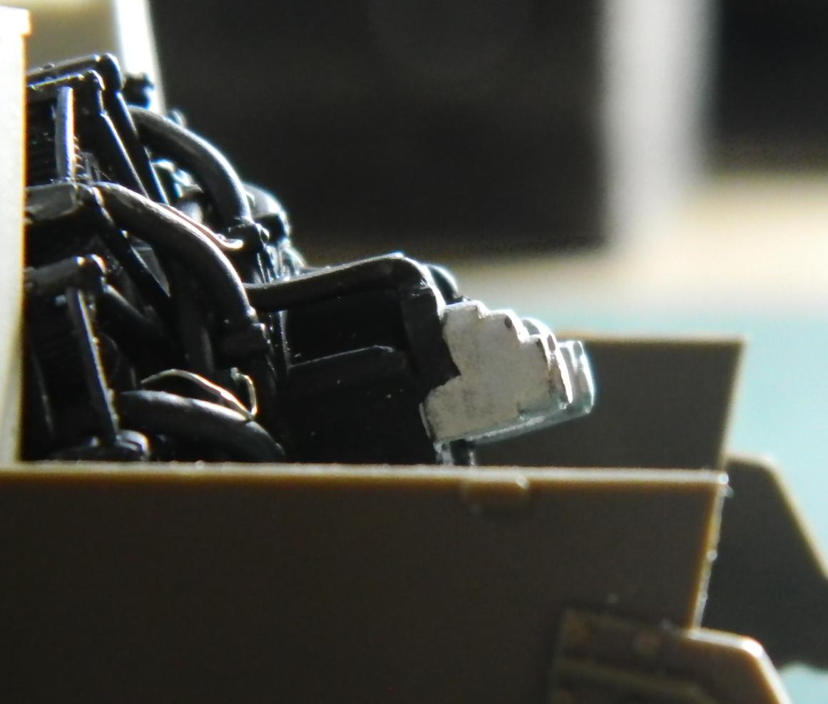
So as of this moment, it looks like everything will fit. Next month should give me that answer. If it doesn’t fit then this build won’t have its engine.
