I ended the previous post with “whew.” I was premature. Putting all the parts together was one (very small) step of a long walk. Now that the parts (sort of) fit, I have to make the parts fit. And I also have to get everything to look integrated, smooth, and have all the gaps filled.
One of the things I noticed when I was at the NASM was that the triangular sections of the wings were actually raised, so .005″ (.127mm) sheet was fitted and putty used to blend the ones that need to be blended:

Naively, I followed the raised lines on both sides of the wing. The problem with that is that the alignment of the lines on top did not match the lines underneath. Of course I didn’t notice this until I’d glued the plastic to the bottom, so I removed the panels on the underside and made sure to align them to the panels on the upper side:
When I separated the upper fuselage from the lower, a section of the elevator ripped out. That needed to be repaired and adding new plastic was the easiest path:

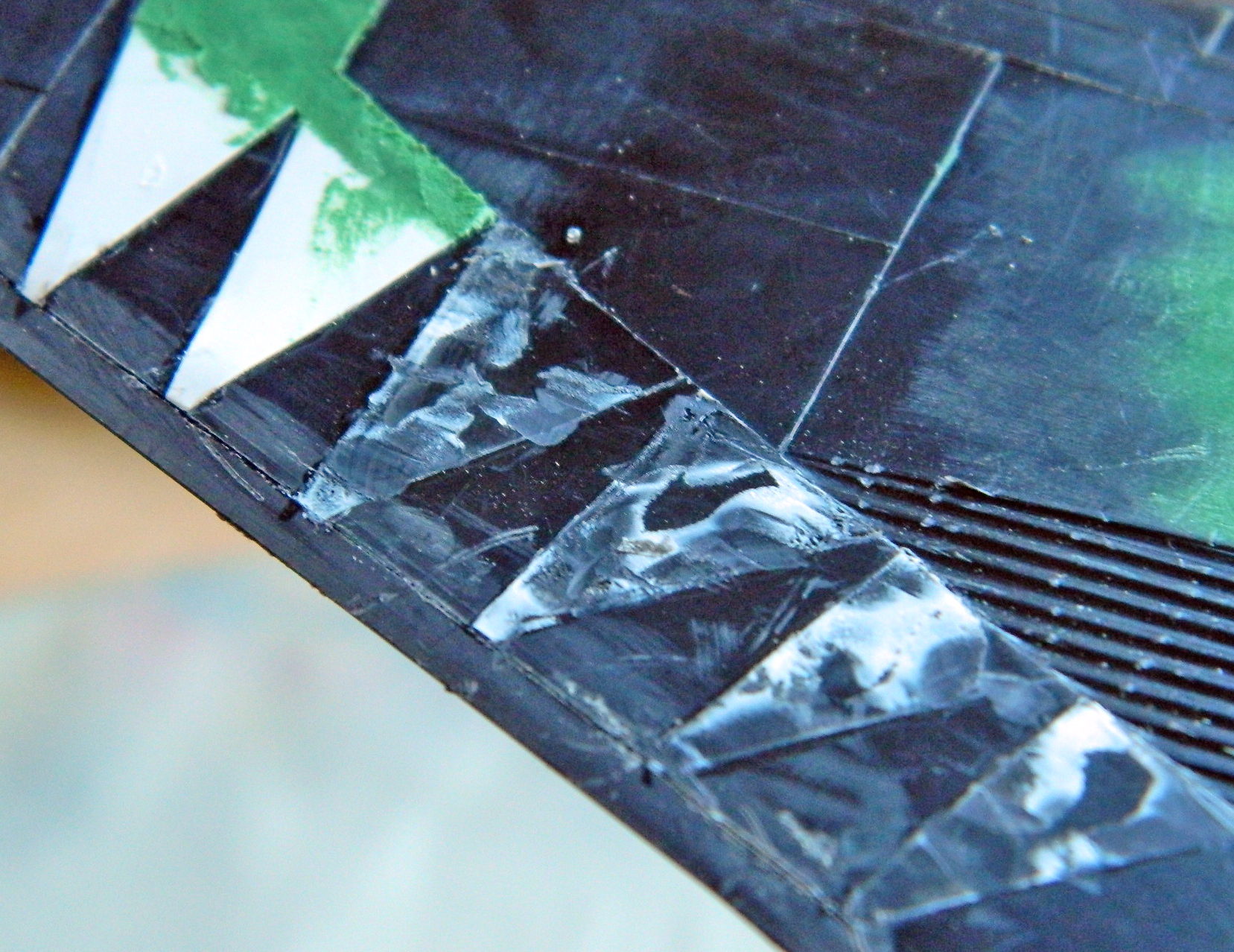
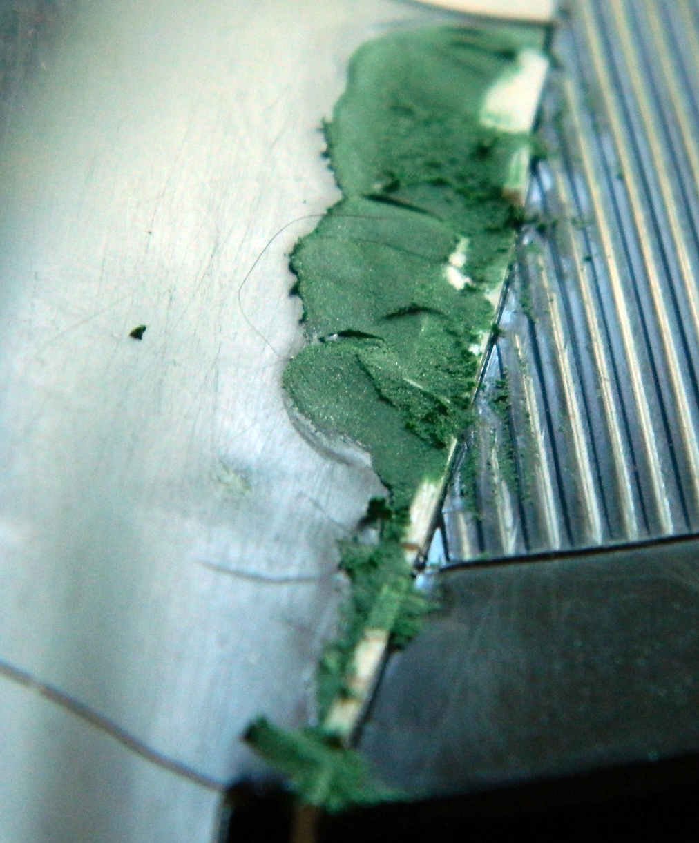
At this point I started scribing panel lines. Though I still don’t figure I’m good at scribing panel lines, I have gotten better at it (and this is good because I have SO much room for improvement!). One of the things I’ve learned with this build is that yes…adding sprue to fill large gaps can be good, and it can also be bad. Unless otherwise shaped, the sprue is round. This isn’t a problem as long as the removal process doesn’t remove more than half the diameter of the sprue. If it does remove more than half the diameter of the sprue, a gap is revealed (hopefully it’s obvious – there’s only supposed to be one line here). I cut away the dodgy section and replaced it with scrap sheet styrene:
Something I didn’t realize at the time is something I will now draw your attention to. Look in the middle photo of the three previous. See that dark, short, line in the area I’d cut flat? That’s a void; there’s nothing there. As I later found out, leaving a void in an area that is going to be both thin and scribed won’t work well. The scribing breaks through the thin plastic and has to be filled. Again.
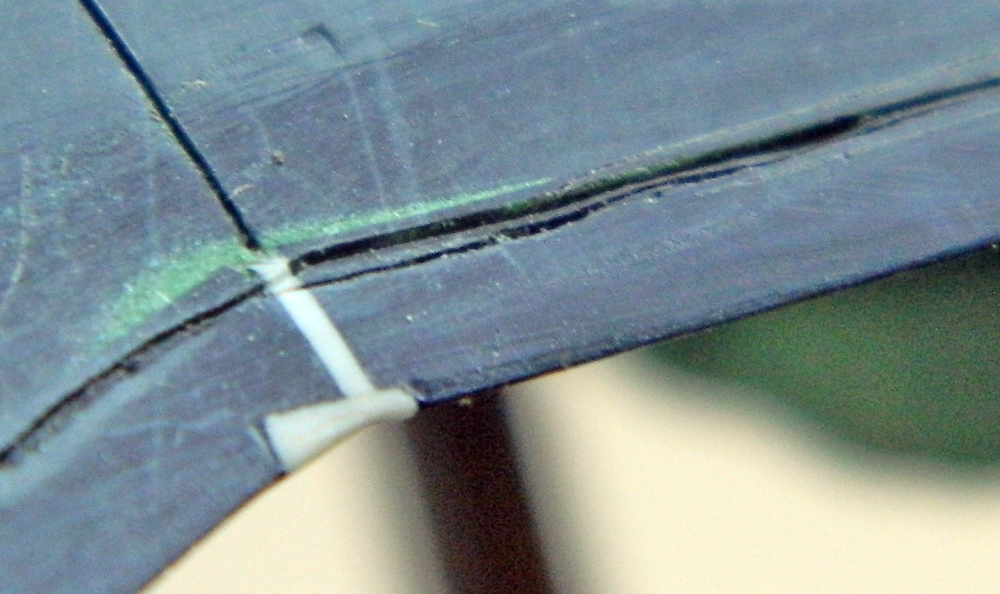
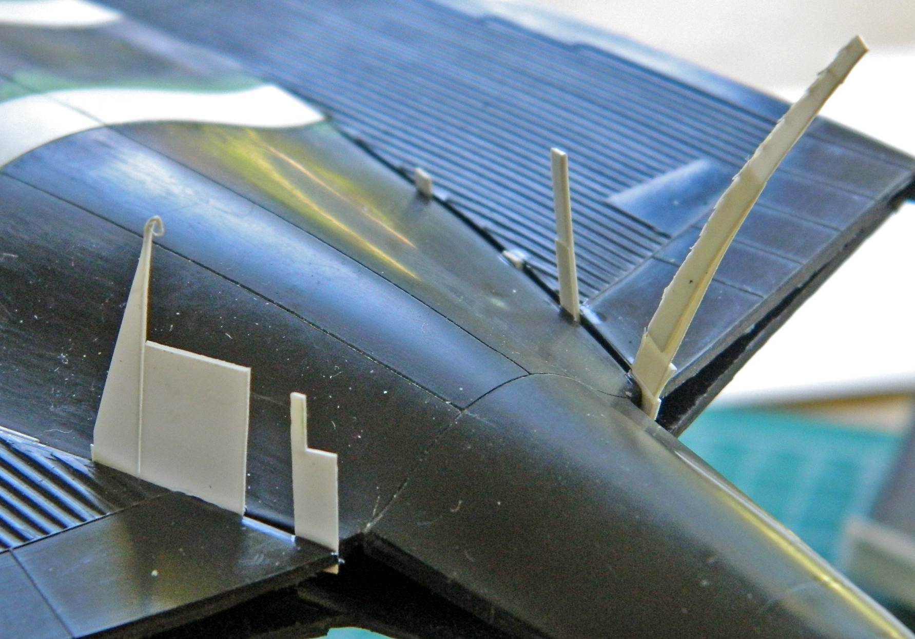
Sometimes scribing panel lines can be interesting. This is a raised panel line in an interesting place:
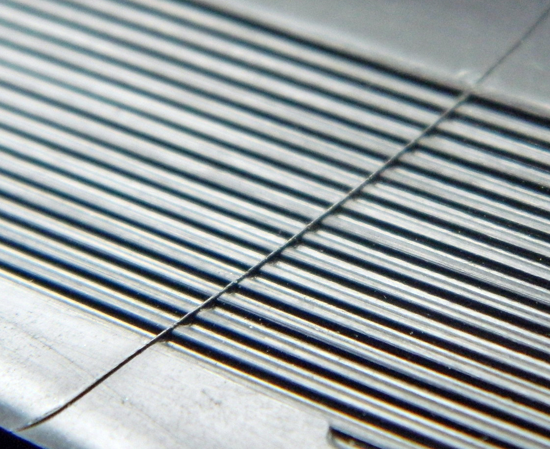
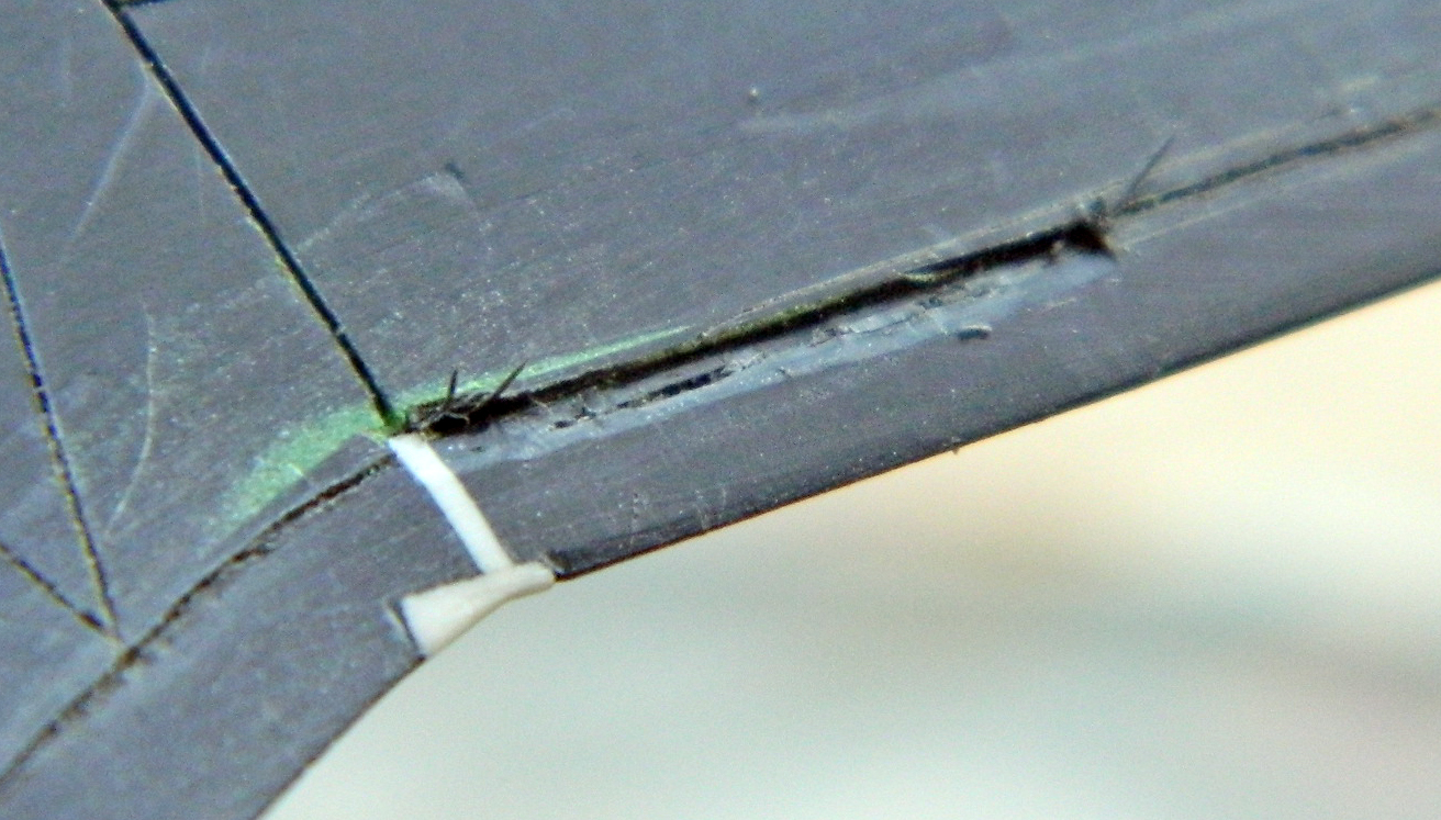
That line need to be recessed. To do that, I had to remove the line so that I could scribe the area:
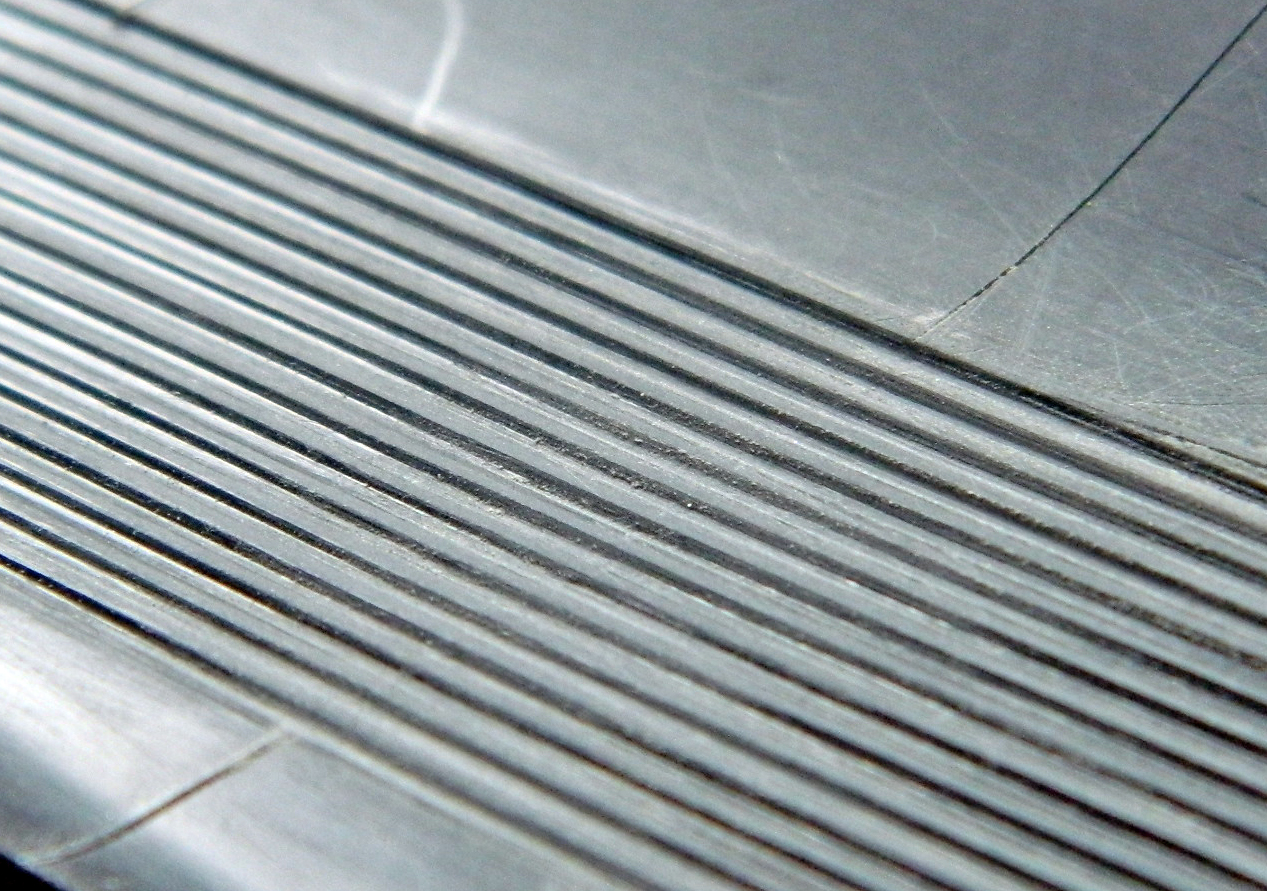

That had to be done again on the other side.
I thought I had already addressed a fit problem but where things actually went after assembly required me to rework the fuselage between the main landing gear openings (the added plastic was filed/sanded to fit smoothly):


One thing I noticed when I got the ill-fitting fuselage section to fit was that there were gaps. The procedure for this build is fill with plastic, shave plastic down, fill smaller gaps with putty. But this time to get access and to rework the elevators and fuselage, removing the elevators (something that was on the to-do list since the elevators droop as #972 is displayed) was called for:

These photos show how far from meeting the surfaces that are supposed to meet are:

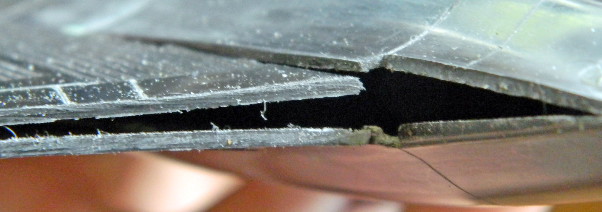
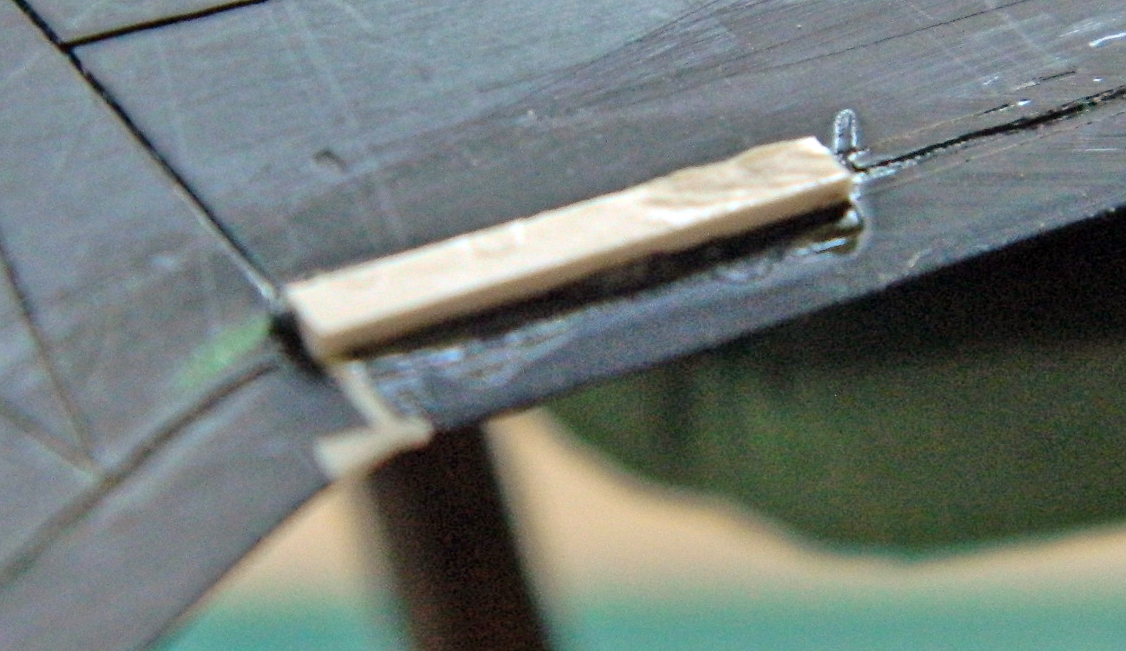
Scrap styrene acts as both wedges to keep surfaces aligned and fill for the gap (a file was used as a wedge to hold the surface in alignment):
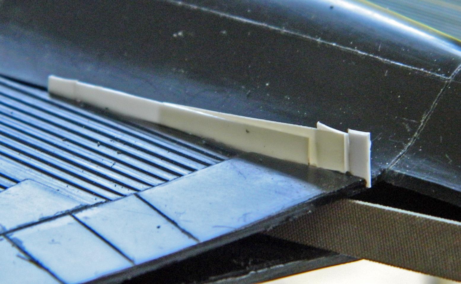
I also added flat styrene to the elevators to close the ends since they’ll be visible once in place:

Lots of plastic needed to be added and then puttied over:

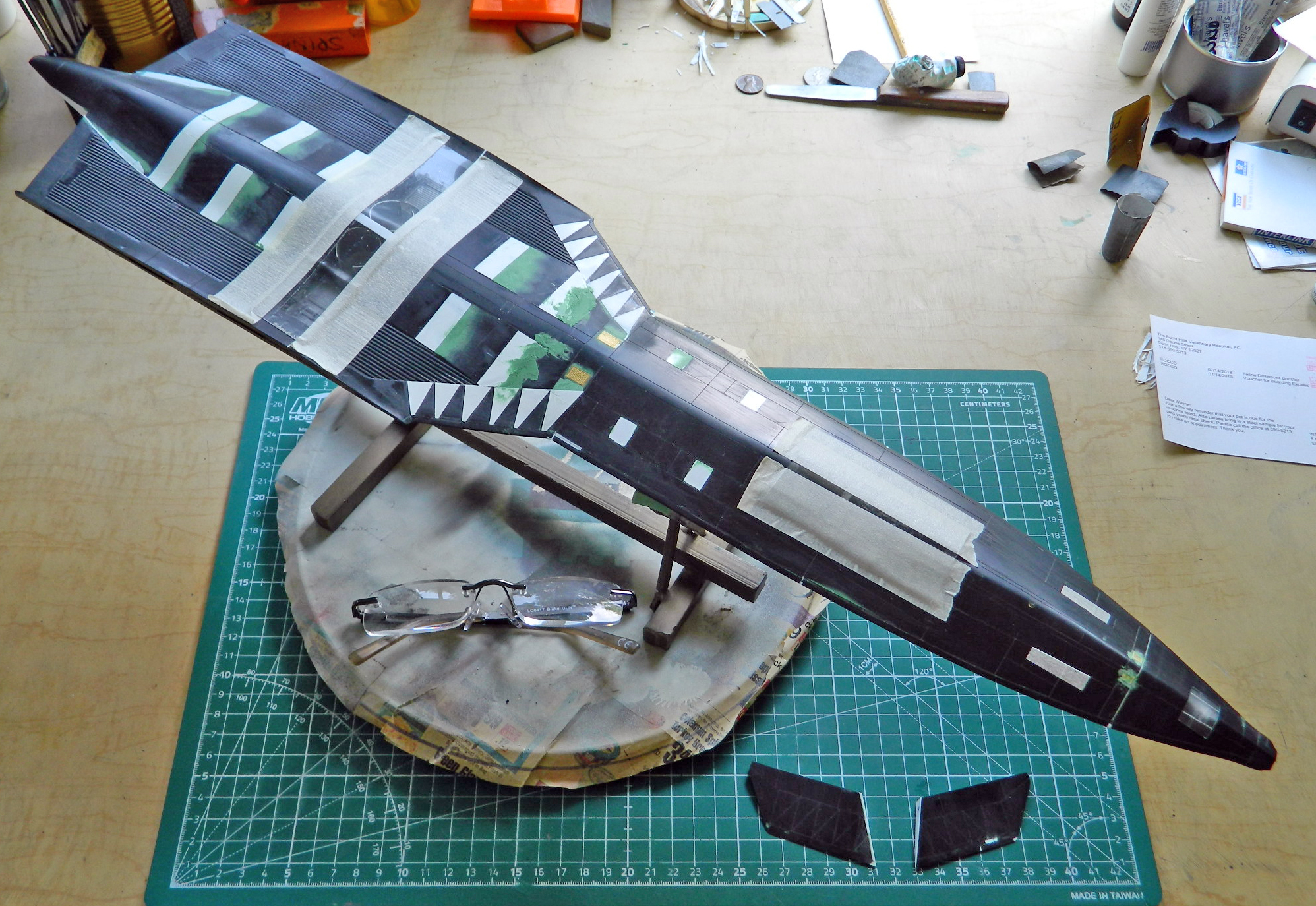
After these steps, days and days of sanding, adding putty, sanding, adding more putty, MORE sanding, ensued. I’m still not done yet and here is where things stand presently. All the white plastic areas are where I added plastic:
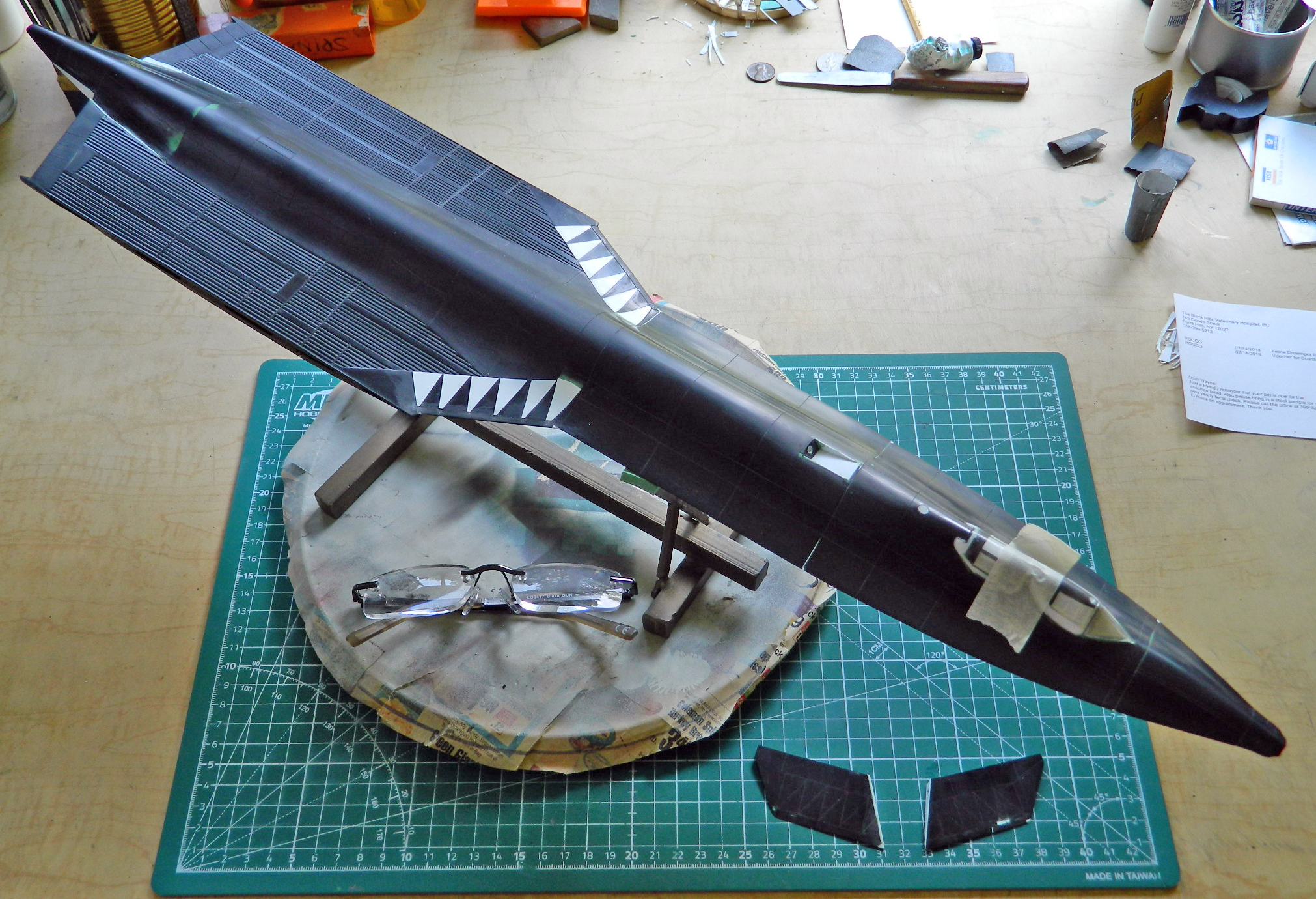
I haven’t even started on the engine nacelles and outer wingtips yet…

I was wondering how you sanded the raised panel line that cuts across the corrugated paneling. I’m building this kit right now and can’t seem to find the right method to sand the corrugated panel sections. I can sand the tops of the corrugated panels but not the bottoms of each channel.
LikeLike
It’s a tedious and annoying job, but you can sand the bottoms of the channels. I used 320 grit wet/dry sandpaper. I folded a small piece of it into a “U” shape, not a “V” shape, pressed it into the channel, and carefully sanded the line down. If the bottom edges of the channels are too rounded for your eye, you can sharpen them using a sharp knife and scraping the sharp joins back to a sharp edge. I didn’t, really, and it’s not especially noticeable. Good luck with your build…I’d love to see how it turns out!
LikeLike