I can often repeat myself. I’m about to do that again. The smaller the details, the longer they take to do. One of my original goals was to see if I could complete this build in under 50 hours. Nope. As of this writing, I’m at 85.75. It’s possible I may get this done in under 100 hours, but I’m not betting on it; you shouldn’t, either.
I finished masking the windscreen:
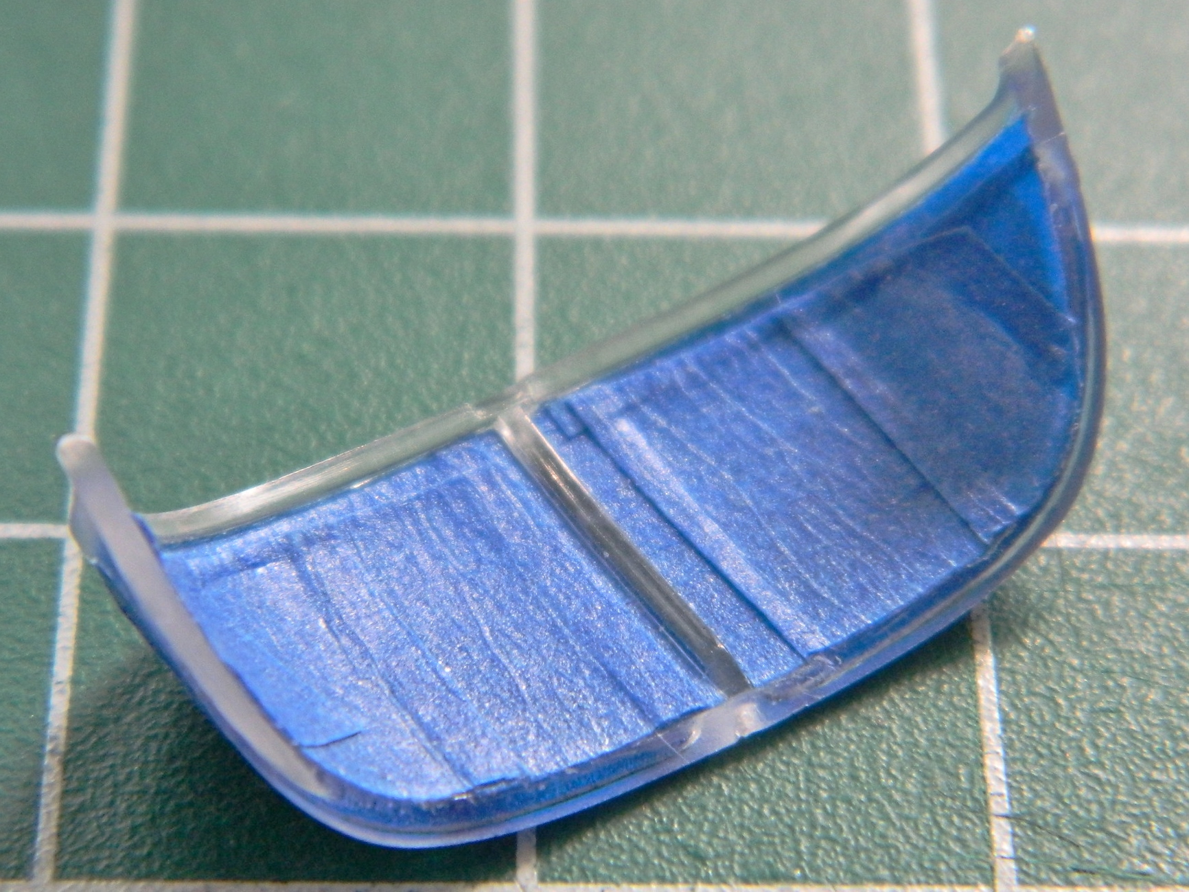

The canopy had rails had to be added:

The top canopy seen above was also masked inside and out. Once the masks were laid down, the interior color was painted on, inside and out. Why outside? Some of the external framing is larger than the internal framing. If, as would seem logical, I’d painted the outside color first, where the framing extends past the inside framing the outside color would show…and I don’t want that. So the inside color will show inside, and the outside color will show outside:
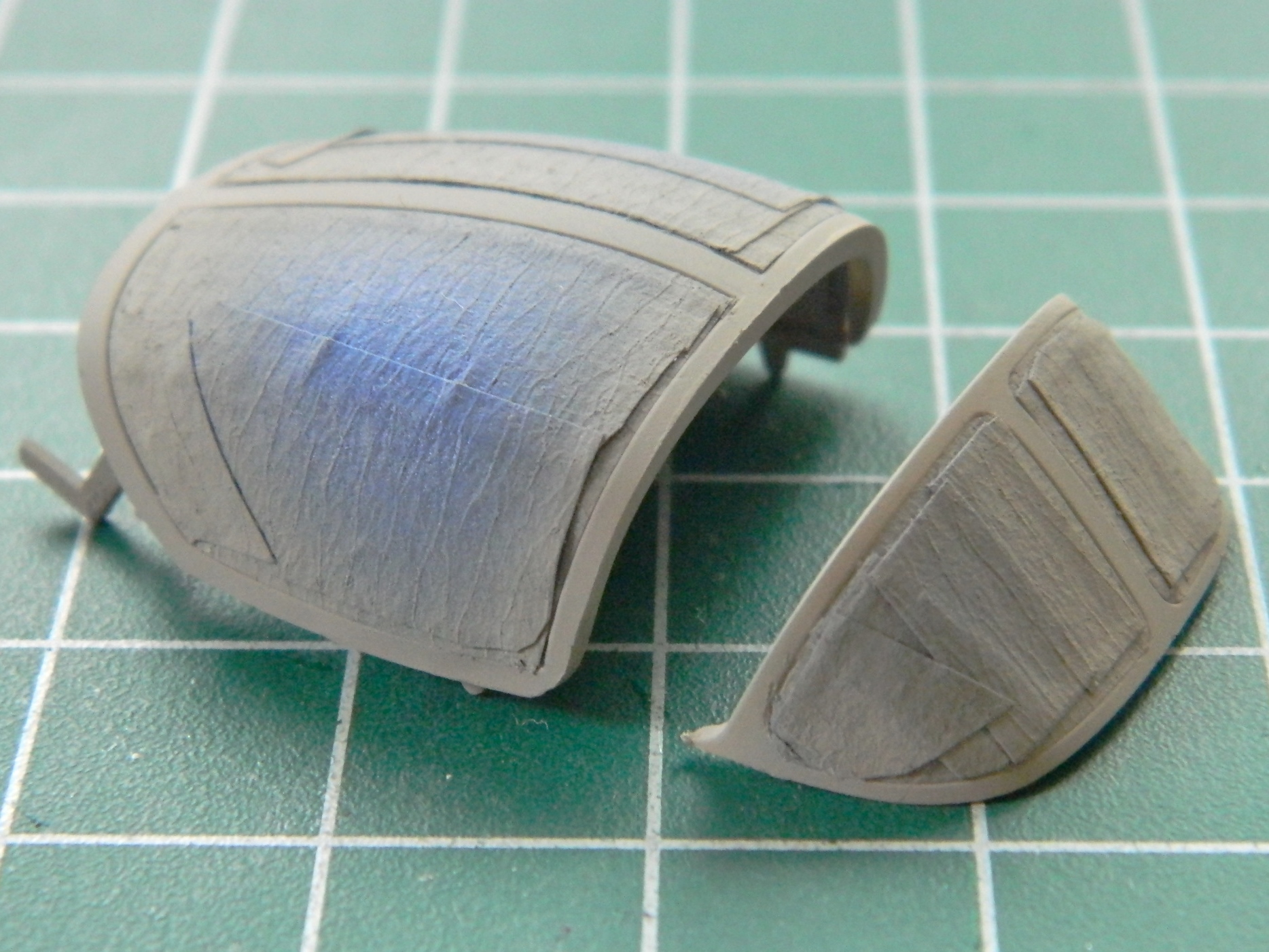
I added the magnetic compass to the top center inside the windscreen, painted it black, and glued the windscreen into position:

Then I fitted the canopy into the closed position and sealed it with white glue to keep exterior paint from infiltrating the interior:

The main landing gear struts have locking arms that keep the gear extended. The recessed rectangular area should be open as when the gear retracts, the brace leg to the left folds into that area, meaning that has to be cut out:

Starter holes were drilled and I used a piece of broken jeweler’s saw blade to connect the holes, then a freshly sharpened knife to smooth it all out:


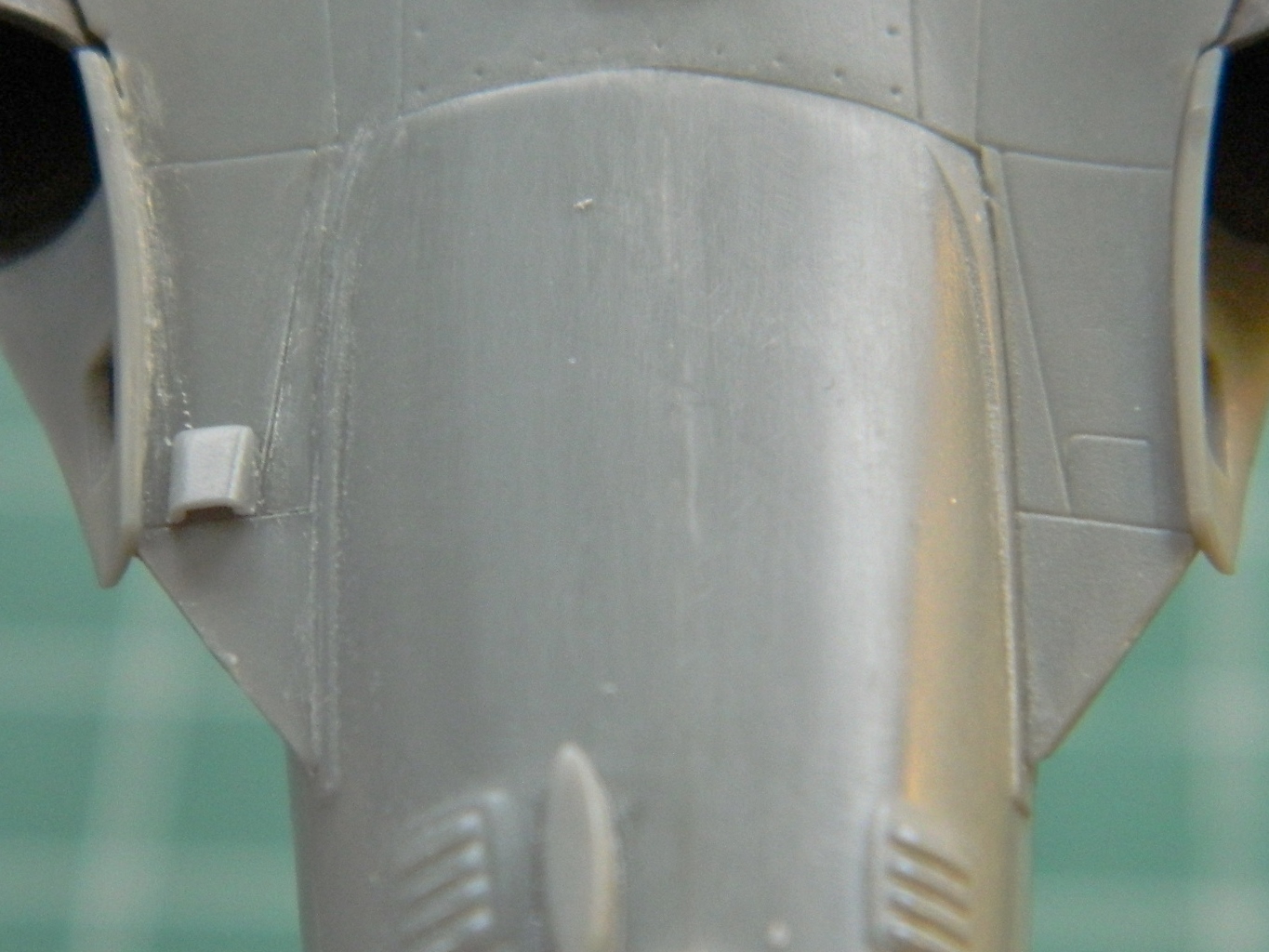
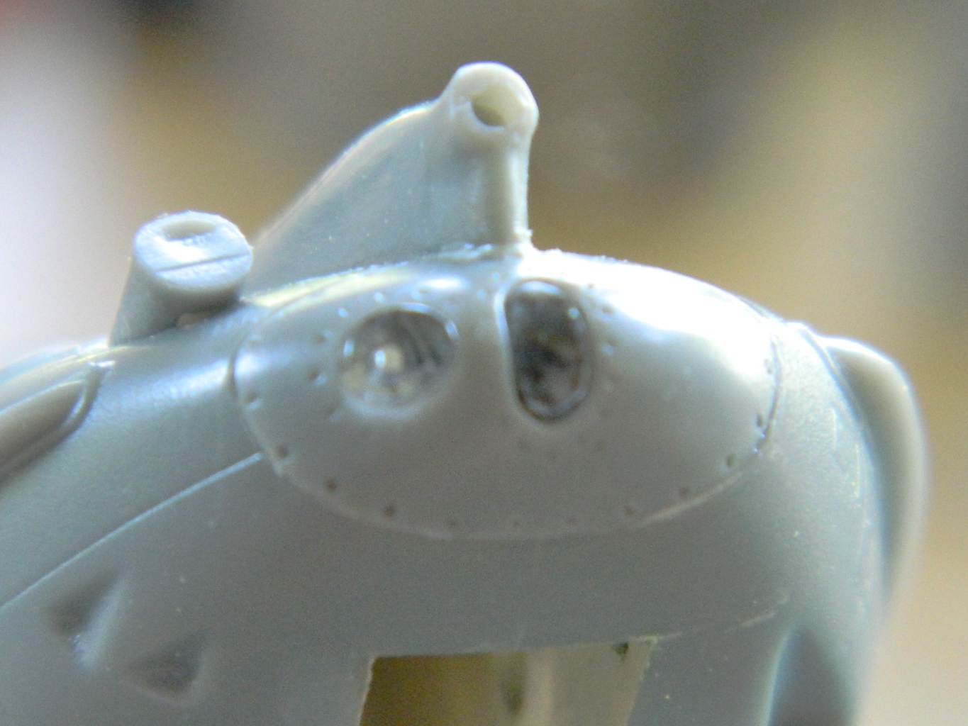
While dry-fitting the gun shroud, I found it didn’t fit correctly. It didn’t settle down into its recess enough and the oval ramp-like area to the left is why. That will need to be cut down (later). At the nose of the fuselage are areas that will be getting clear parts installed. The round area is a landing light and the oval area is…well…I dunno what it is. I just know it’s clear, it’s the size of a large grain of rice, and it certainly had me concerned (they both did, actually):
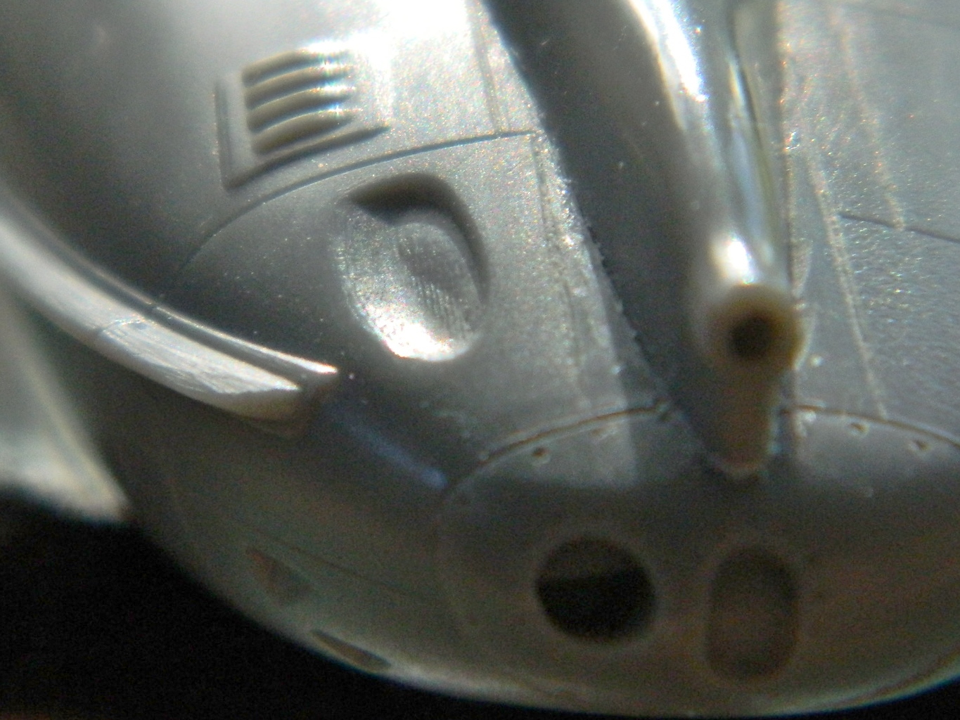
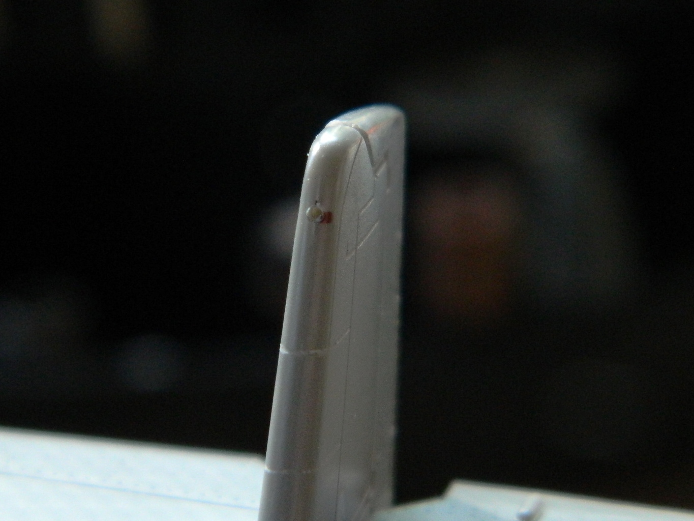
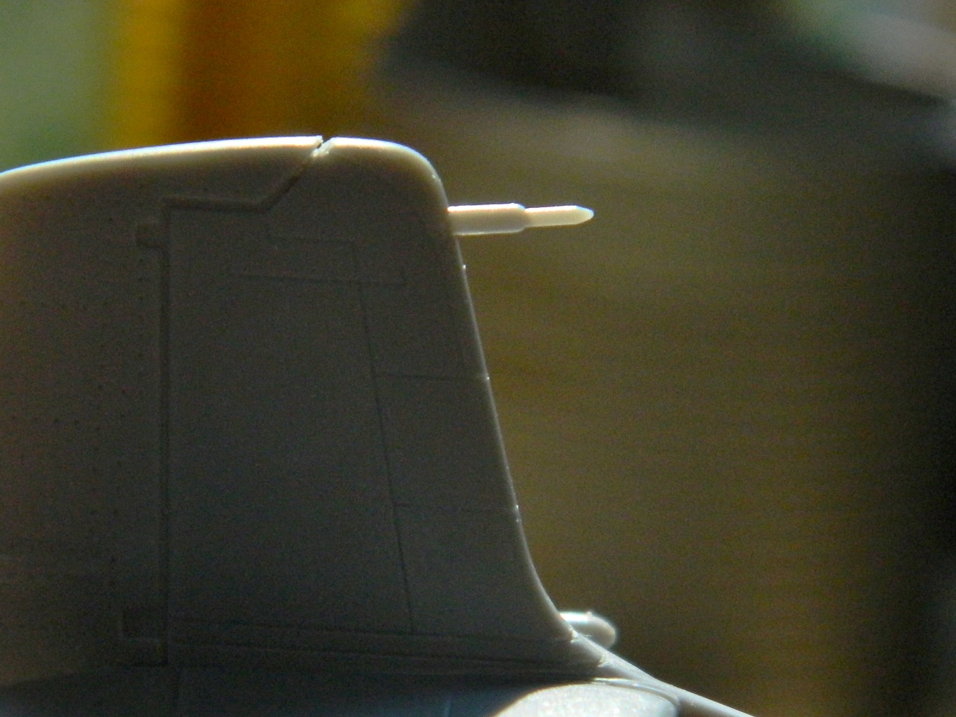
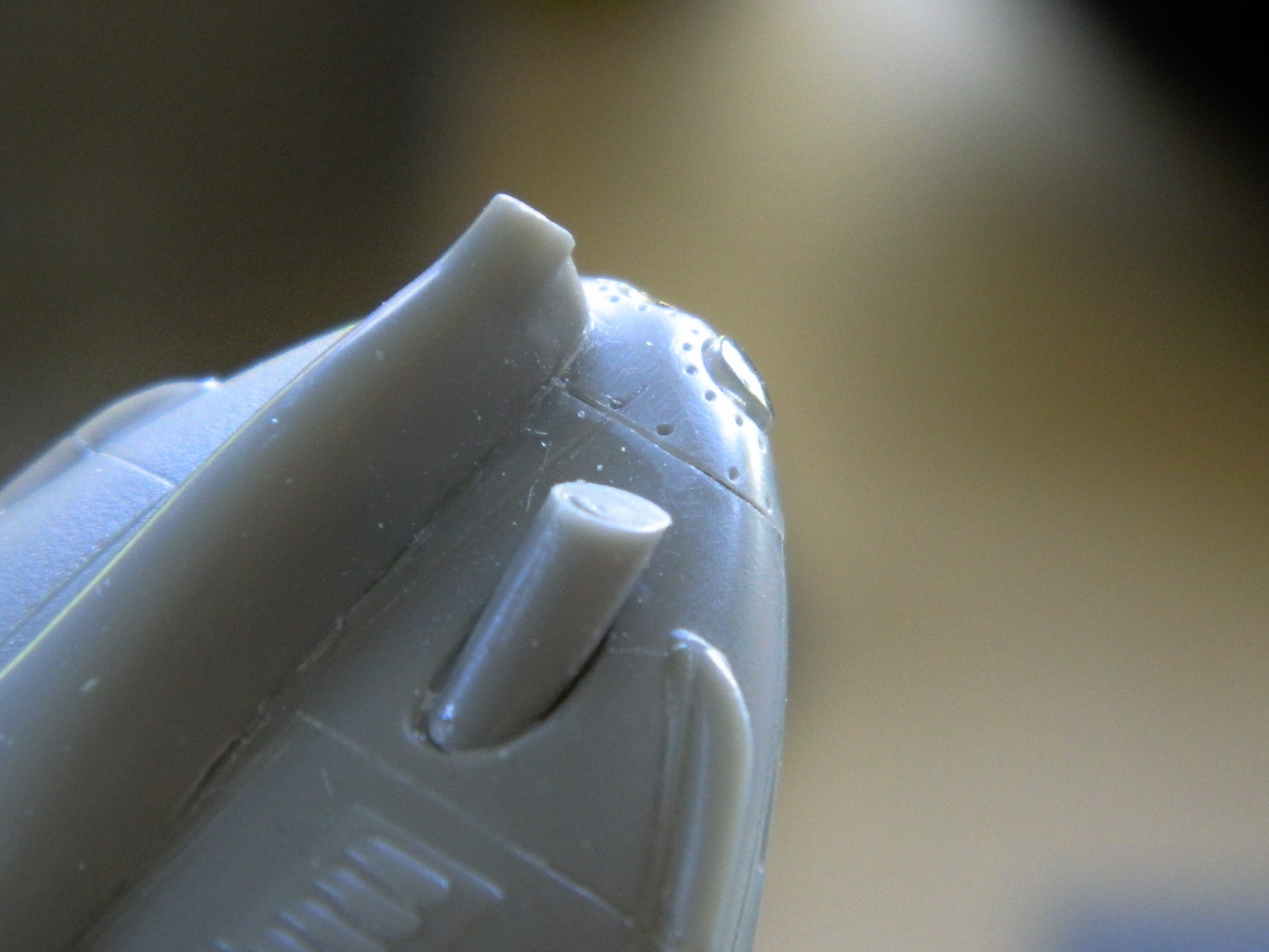
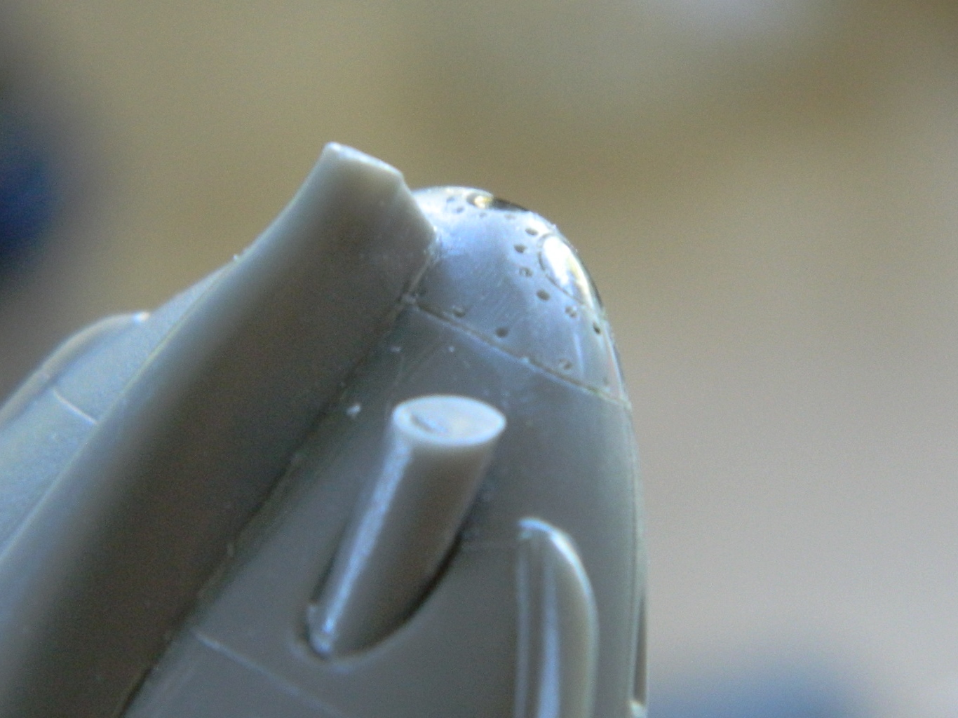
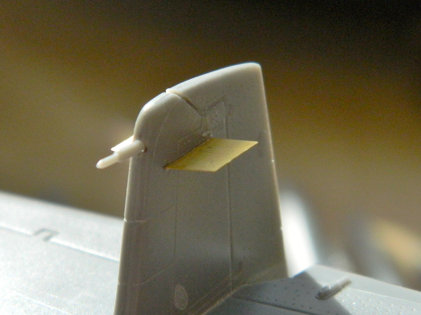
There is a curious omission with the kit’s directions. All my references show the pitot tube (a device that tells airspeed by the air pressure created by motion acting upon it). The kit supplied a pitot tube. The parts lists states it’s not used. That’s incorrect. Looking at the area at the top of the vertical stabilizer shows something else interesting. Most of the socket for the part to fit in has been molded. But the outside of that area is molded solid. Interesting… Also incorrect. I drilled out the socket and added the pitot tube (if you look closely at the first photo, you can see the area behind the black dot is lighter; that’s where the socket was molded in):
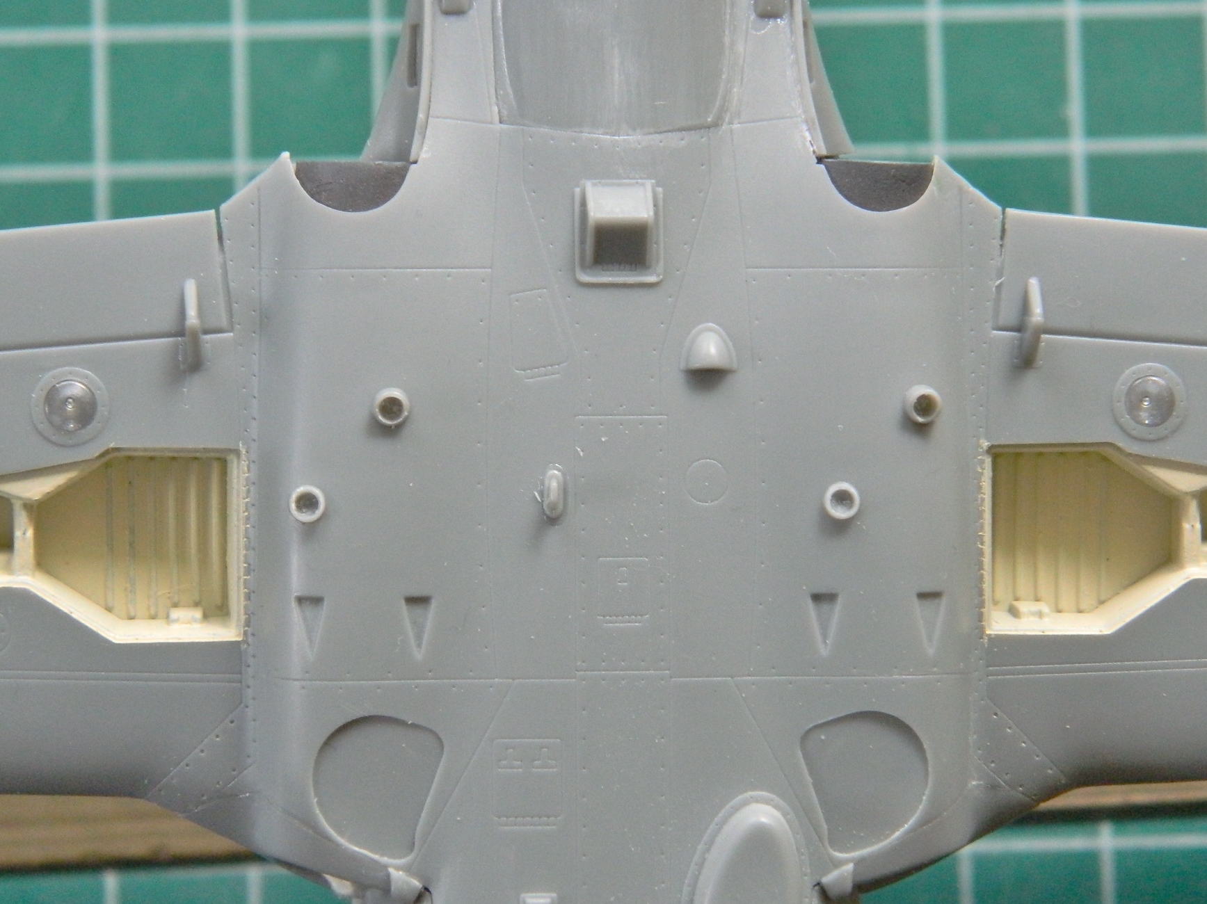
I flipped the model onto its back and started adding small vents and antennae.
I did mention “small,” didn’t I?:

The bases of all the fin-style antennae are too thick. I’d already thinned the ones on top, I also thinned the bottom ones:

The color of the nose-wheel bay needs to be brought down to the fuselage and to do that, I needed to fill that gap with putty and paint it:


There are round vents on the underside that were WAY too thick. They’re still too thick but since this is an OOB build, I won’t be replacing them with brass tube the way I’d like to. I drilled them out to improve the scale appearance:
When I started assembling the under-wing stores I noticed is that some of the stabilizing fins are far too thick. Those had to be thinned more to scale:

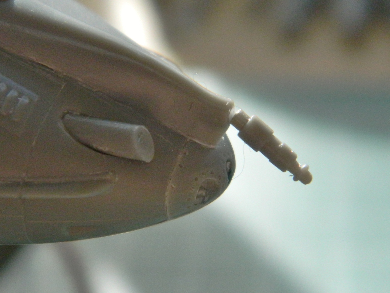
Then I had to ignore my apprehension about the clear parts that go into the nose. I got the oval-shaped part right the first time! (Considering how nervous I was, I’m surprised I didn’t launch the clear part into a multi-hour session of flashlight-in-mouth-crawling-around-on-the-floor-examining-each-square-inch fun). I had painted the area behind it black and the area behind the light silver. I wasn’t so fortunate with the fit of the nose light, though. You can see how far it sticks out and it’s supposed to be flush:
I filed the protruding area to fit the curve of the nose, then used successively finer sandpaper until I’d removed all the sanding scratches. (Had it been a canopy, the next step would be to polish it…for hours…but it’s not so I didn’t) (and also note how nicely the gun shroud sits in its oval mounting area):
I’m pleased with the end results:
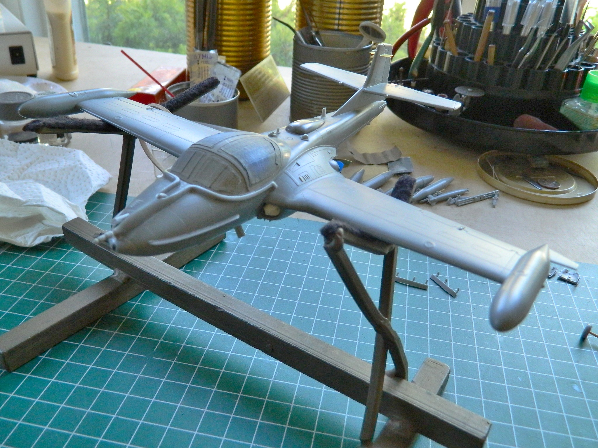
It took some time, but now all of the detail parts are about ready to start hanging onto the kit. The ordinance and drop tanks will be added after painting:

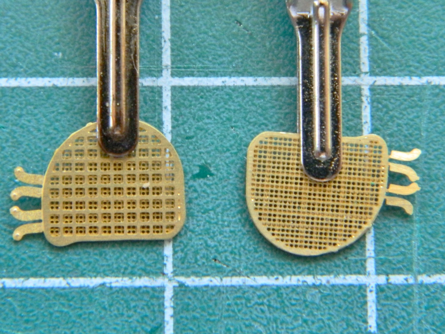
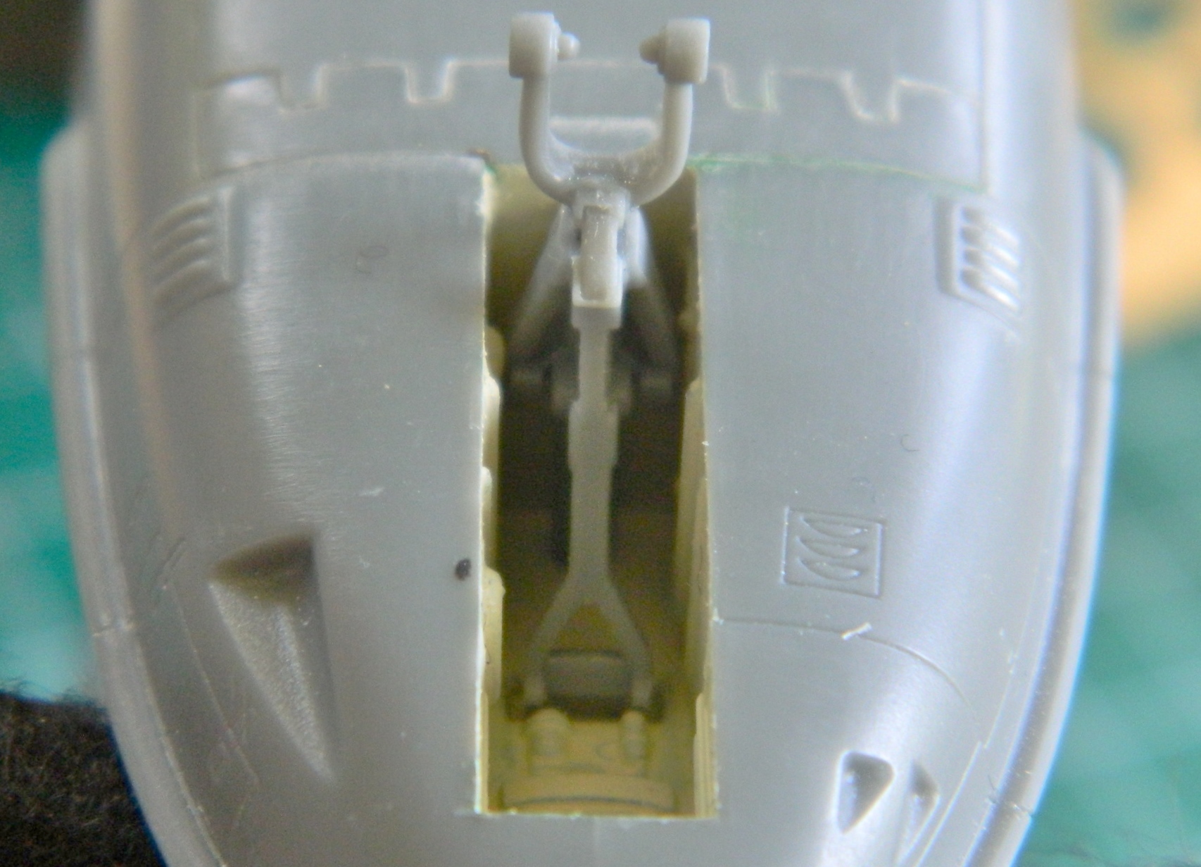
The A-37 sits so low to the ground that it was quite prone to sucking bits of crap into the intake. A jet turbine is a finely balanced bit of kit and does NOT like being unbalanced (unlike myself, who’s made a lifestyle out of being unbalanced) and quits in a huff when that happens. Sometimes it quit in something much more dramatic than a mere “huff.” The fix was to mount FOD (Foreign Object Damage) screens. The pilot(s) could raise or lower them at will from inside the cockpit. The kit offers nicely done two-part FOD screens that had to be assembled. I briefly considered soldering them but realized that was taking things too far; superglue would work just fine:
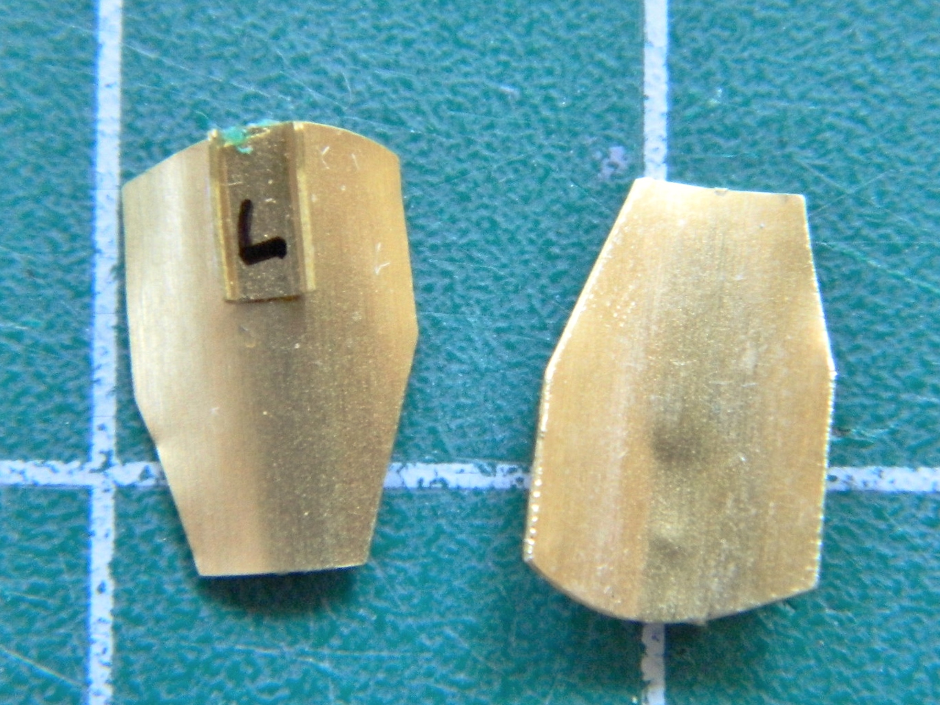
Next, I had to curve the exhaust deflectors and glue the mounting brackets to the back of them:
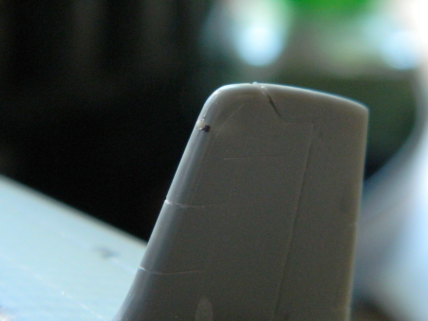
At the top of the vertical stabilizer a pair of antennae are supposed to be attached. There’s a problem with that…the antennae that are supposed to be mounted to the plastic is .005″ (.127mm) thick. That’s not enough surface area to keep them there (a gnat landing on it could cause one to pop off), and the attachment point is a very fine recessed line which helps as much as a screen door on a submarine does:

One of my line scribers actually cuts plastic away leaving a slot and that’s what I used to cut slots the PE parts will be glued into:

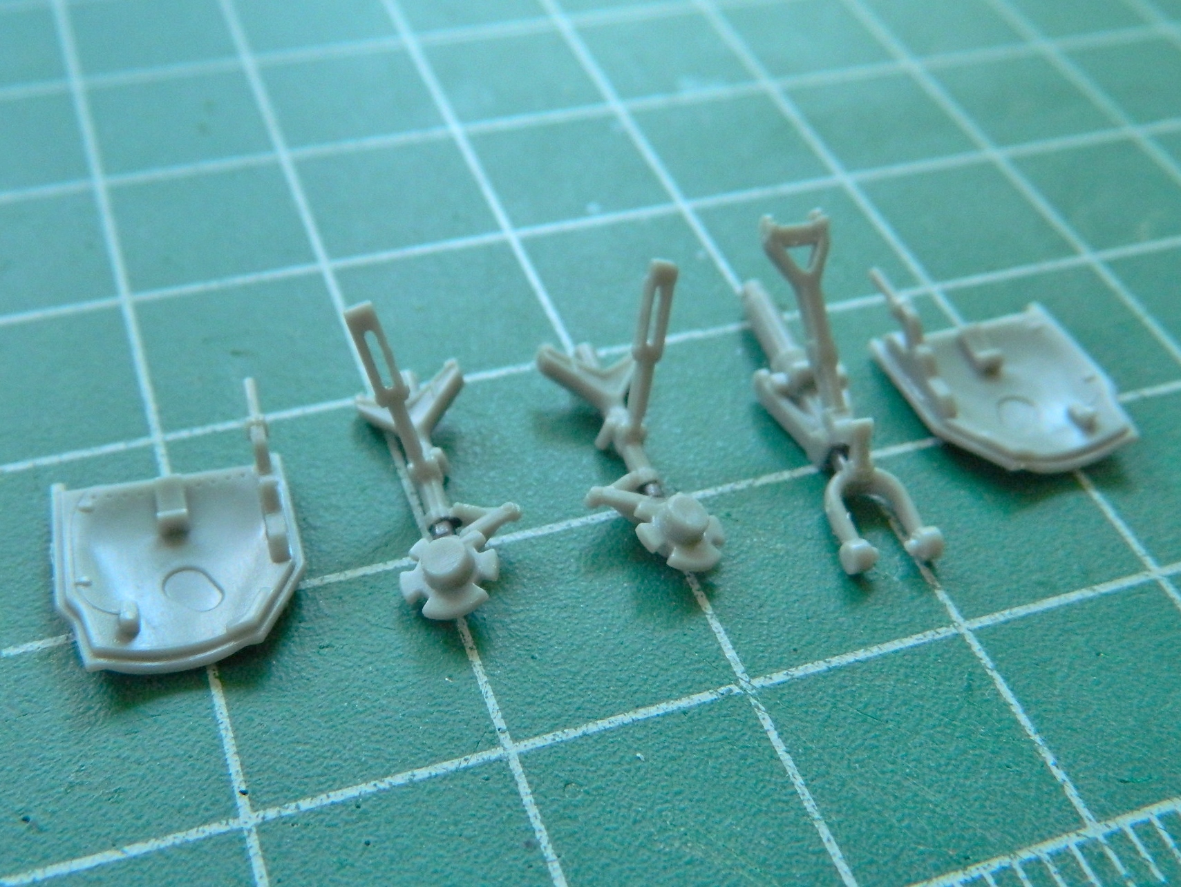
While I’ve been working on the larger assemblies, I was thinking about how to paint the landing gear parts. Some of them are very small and not only would they be a bitch to handle while painting, the airbrush would blow them off the painting backdrop if I wasn’t holding them. My solution was to attach them to the parts they get attached to which are larger and easier to handle. That meant I had to dry-fit the parts and align them:


This I can work with:
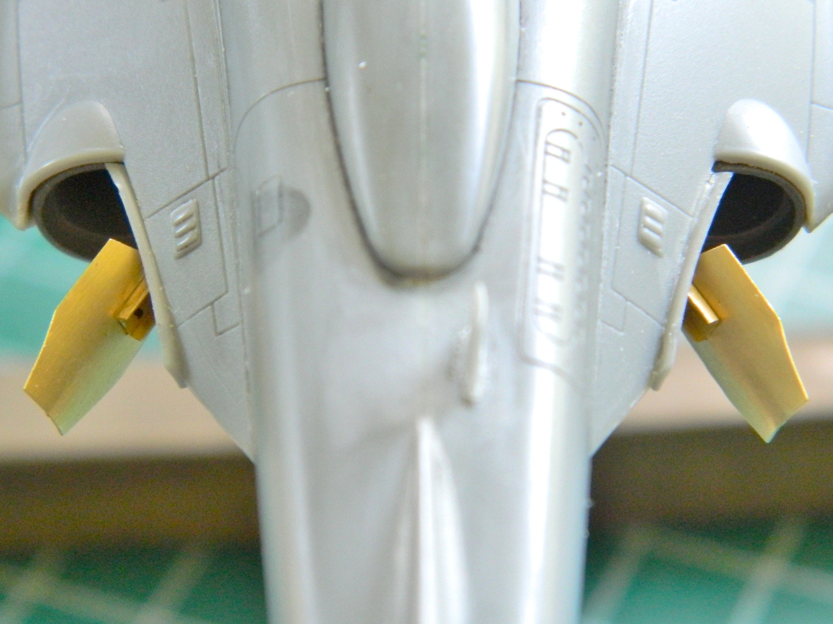
Then it was time to start hanging the last of the PE parts onto the model. First I did the exhaust deflectors:
Then I did the fin antennae on the vertical stabilizer (and the FOD screens):

And then I managed to knock the damned thing off the stand and snapped the refueling probe off:
So that got glued back in position. Thank you EVER so much, Eris and Loki.
To keep the exterior color out of the differently-painted landing gear bays and off of the exhaust nozzles, they were all masked off:

And y’know? I think I’m ready to start tossing paint at this thing:
Next is airbrushing…
