Having decided to scratch-build the sides of the cockpits, I needed to know exactly how the cockpit tubs were going to fit into those spaces and have all the details added so I could get an accurate read on what needed to be where so it would all fit. This is what I started with:
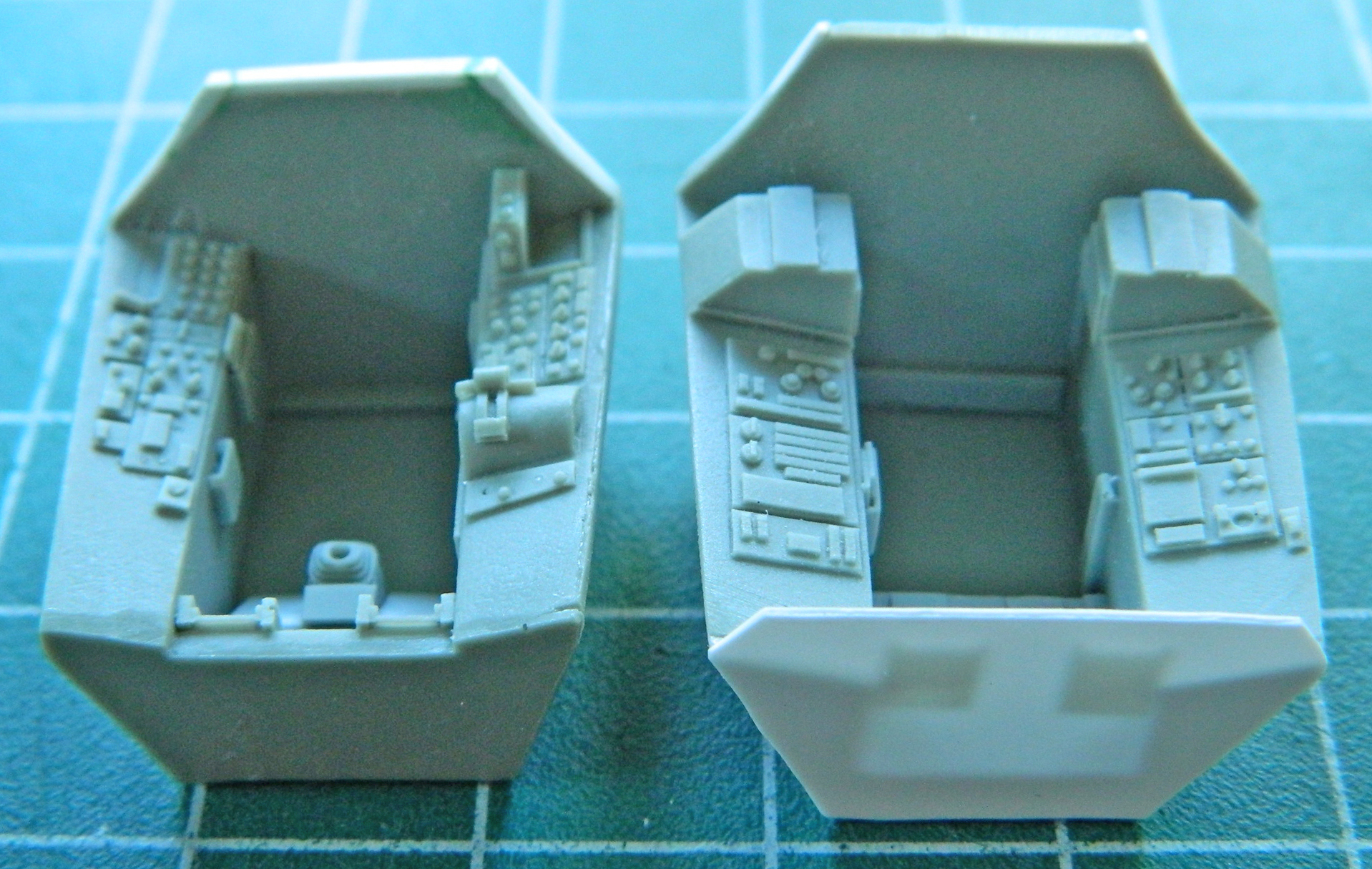
Neither tub is 100% accurate. Unless I wanted to entirely scratch-build these tubs, AND I DO NOT, it will do. Reference photos showed me that this section of the side needed to be removed so I could put less inaccurate stuff in there. First I went at the RSO’s cockpit and made vertical cuts to define the amount of resin that had to go:

Then I hogged it out with my Dremel:

With the bulk of it removed, I refined the shape with a sharp #11 and backed it with a scrap piece of .010″ (.254mm) styrene:

Then I removed the forward section of that pedestal to allow room for the bits that I want to put there:
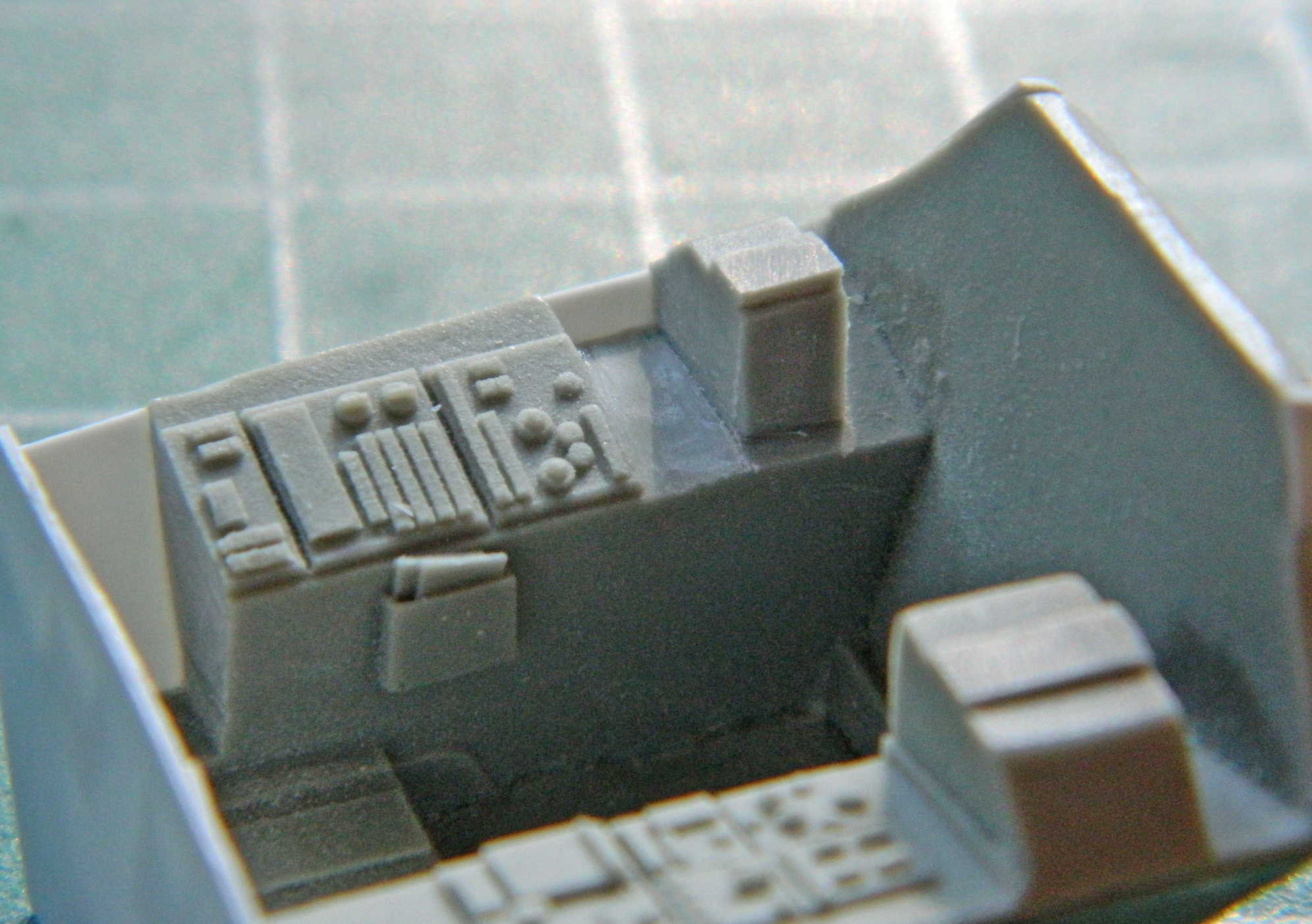
Now that there’s space, time to fill it. Using more scrap styrene I built the stack of Mysterious Bits that go there, detailed them, and then used the aluminum duct tape again to create the housing I needed for the stack:

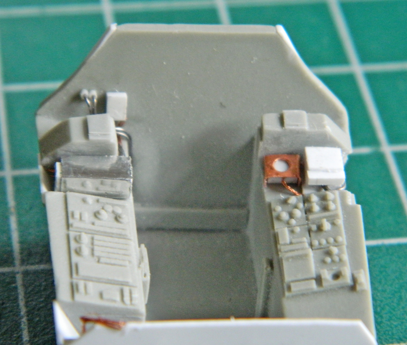
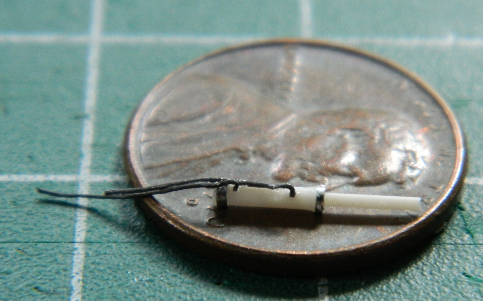
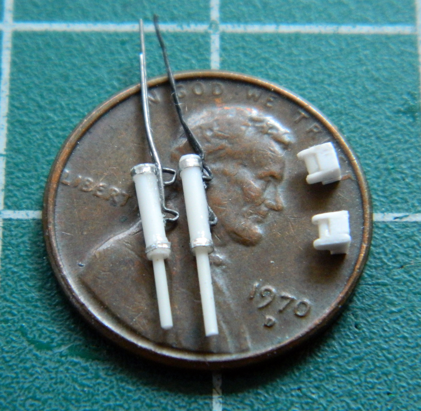
The completed bits get installed and wiring added. For the small part at the lower left I used 40awg wire to create the harness…then cut down the other pedestal to have a place to put more Mysterious Bits:
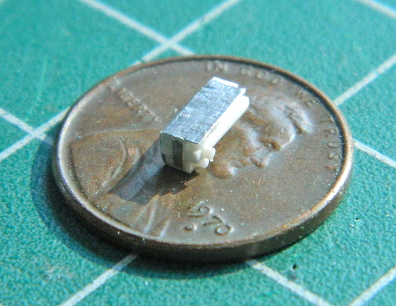
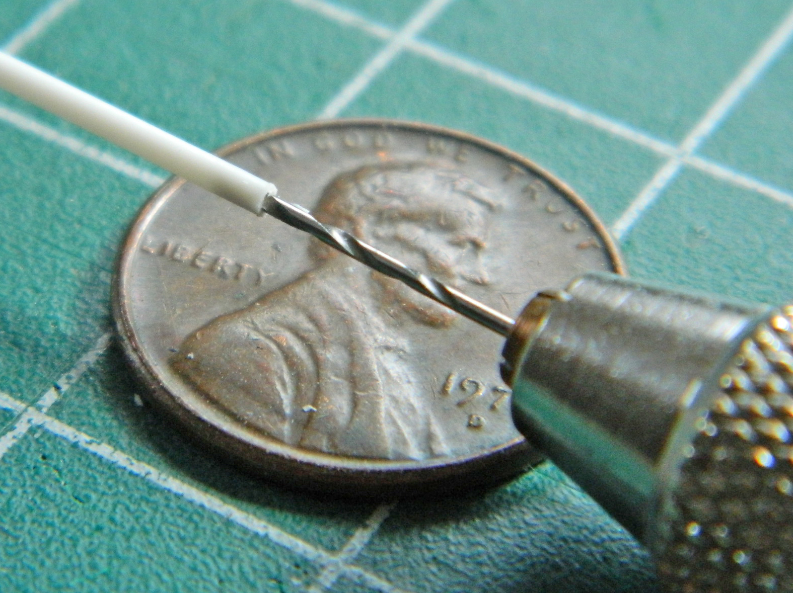
Then the Mysterious Bits were made. I used .010″ (.254mm) copper shim stock to make the housing for the one Mysterious Bit, using the punch/die set to create the round opening at its top and added more 40awg harness:
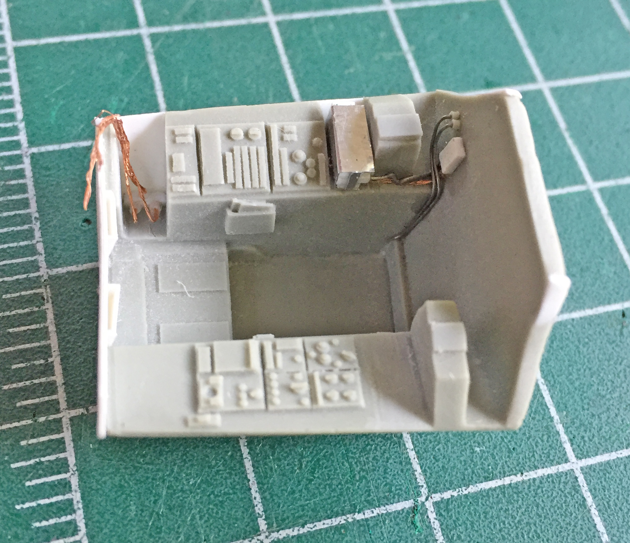
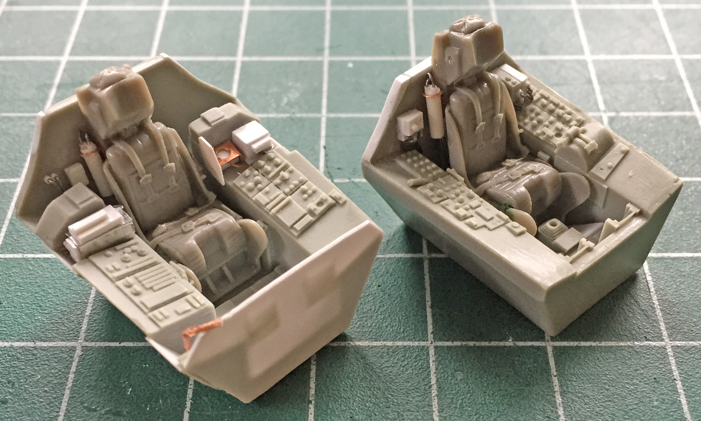
I repeated the process for the pilot’s cockpit…and didn’t take any photos until it was done. There will be a couple of more items added, such as the mount for the canopy opening cylinders, but this is the basic redone cockpit tubs (with the seats just placed in to see how it all fits…and it does) and how it looks:
First I did the mounts that go on the rear bulkheads of the cockpits using scrap styrene:
I used .062″ (1.57mm) styrene rod to make the cylinder and .035″ (.890mm) styrene rod to make the rams (the rod that moves in and out of the cylinder). The cylinders are a bit short so that I can adjust them later to fit into the available space. Fitting these things has the potential to be a bitch so I wanted to build in some adjustment. Until all the associated parts are actually mounted, I don’t know exactly how long the finished sub-assemblies will need to be. This started by center-drilling the .062″ (1.57mm) rods to accept the .035″ (.890mm) rods:
That will enable me to slide the .035″ (.890mm) rods out if the end parts are too short and I can always trim the .035″ (.890mm) rods if they’re too long.
I added the bands using the aluminum duct tape (love that stuff) and .010″ (.254mm) bits of lead wool to replicate the hydraulic lines:
Then I did that all again for the other hydraulic unit and ended up with all of these (on the second unit I used .010″ (.254mm) solder to see which I like better…and the solder is the winner…it’s less fragile than the strand of lead wool is):
Now that I know what will fill the cockpits, it’s time to start by building up the cockpit walls (and I’m not unmindful of the irony of having to put back plastic to the areas I’d carved away to use resin parts I’m no longer using). These are the rough blanks for the RSO’s cockpit:
I started this process by making the main body of the side panels, gluing it into position, and then engaging in styrene mosaic to get mass built up in the areas I wanted it, starting with the RSO’s cockpit:

Next ensued much filing, sanding, scraping, and a little bit of putty:

And then I did it again for the pilot’s cockpit:

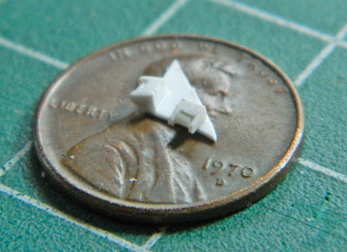
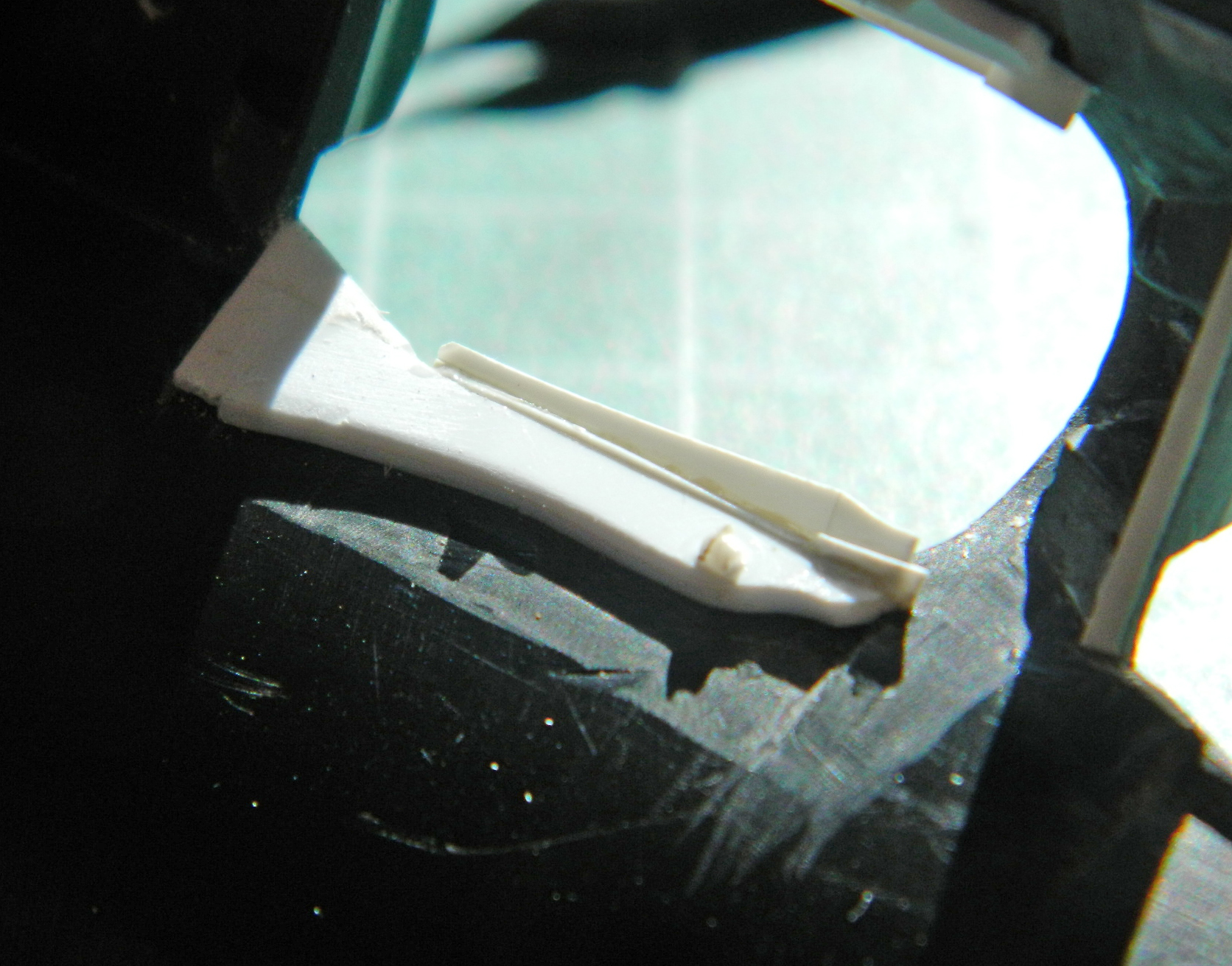
One of the things I noticed about the True Detail cockpit parts was the “fit” between the pilot’s instrument panel and the coaming that goes over it. In short, they didn’t really fit with each other. At the top of the panel is a gauge with a square bezel and it’s supposed to fit up underneath the coaming…and the resin part does not. I decided to see if I could use the .010″ (.254mm) copper shim stock and make one.
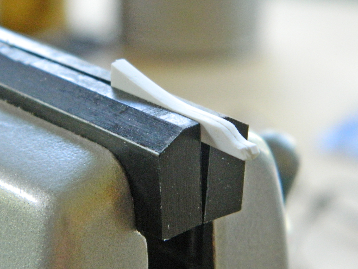
I transferred dimensions from the resin part to the shim stock and roughly cut it out. Because I was going to have to make tight bends in a very small area, I decided to anneal the copper before trying to bend it and thereby remove its resistance to bending. I got it to work:


Satisfied with the result, I added the details with scrap styrene:

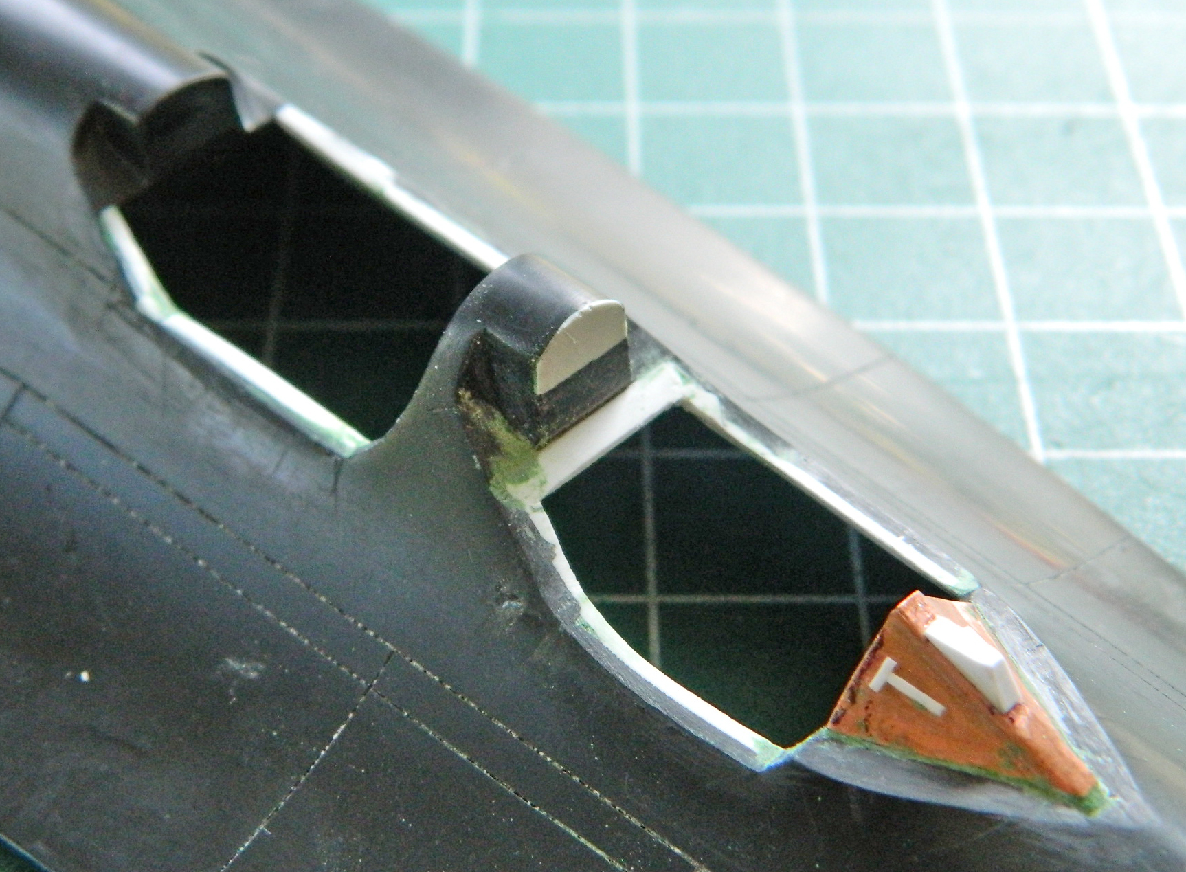
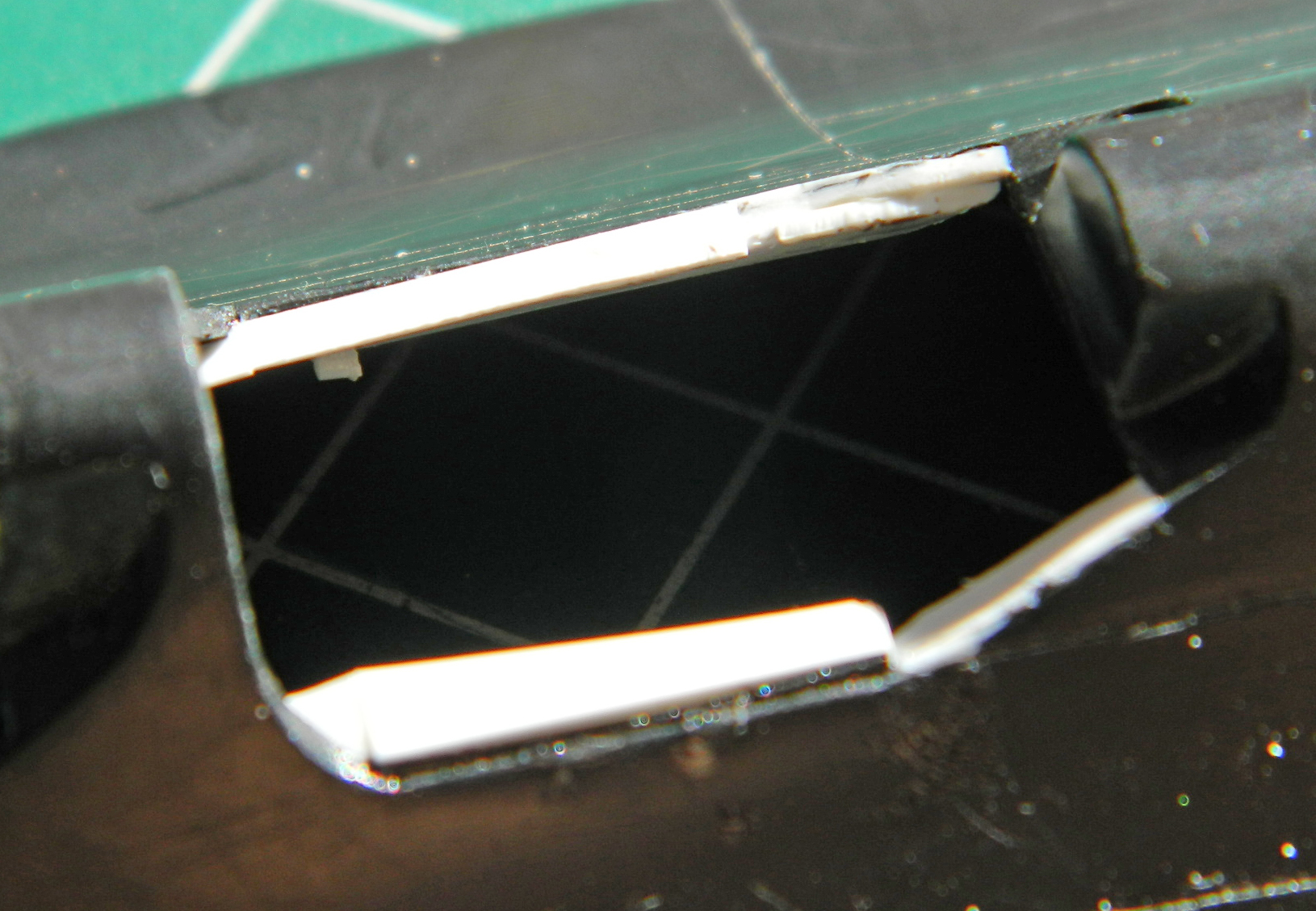
With that all done, I decided maybe it was time to see if things fit…and they do. Putty was added at the edges of where the coaming mounts:


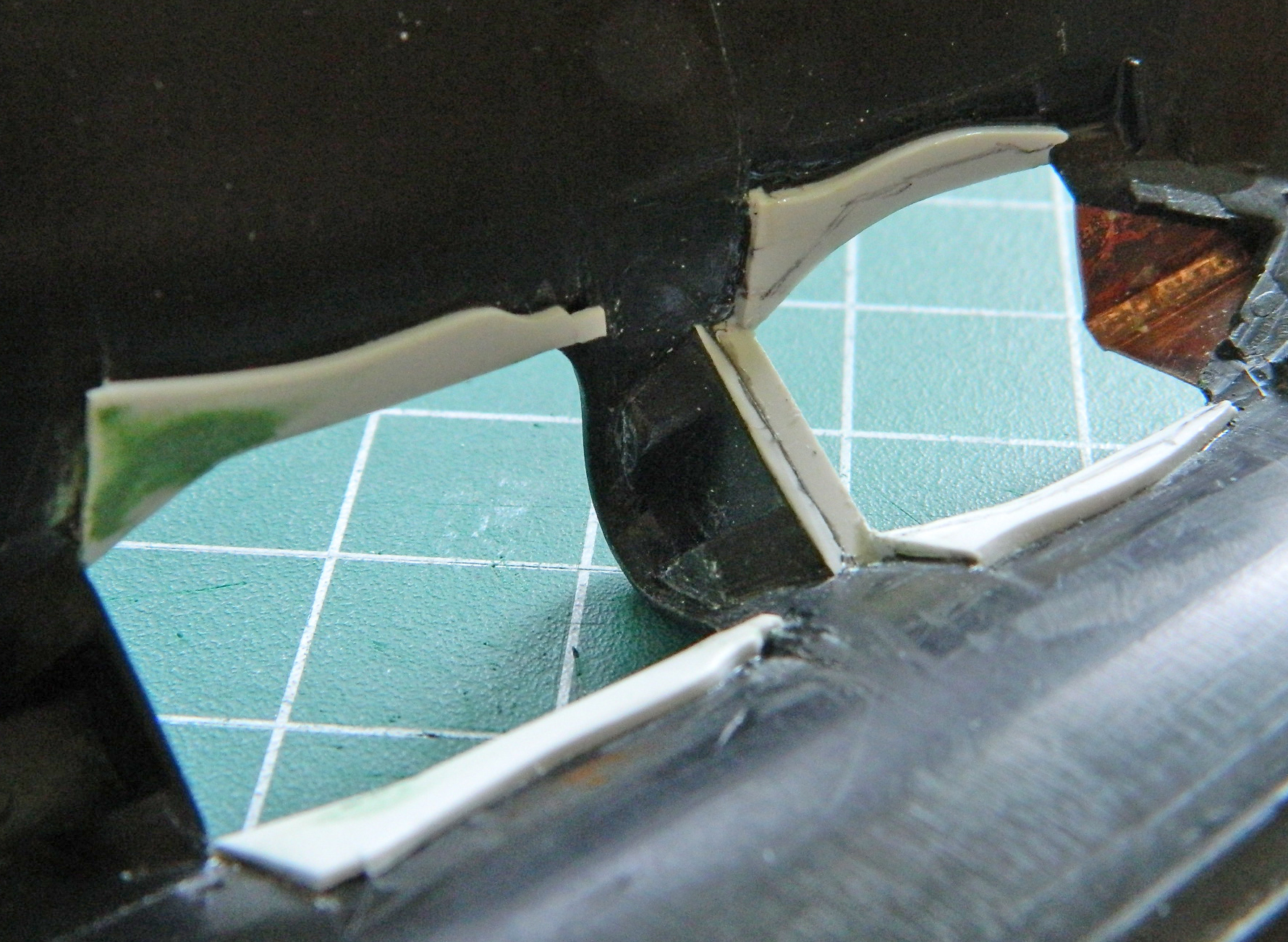
Dry-fitting the cockpit tub showed me that I had to add more styrene to replace what I’d already removed. The result isn’t 100% accurate due to the a-bit-too-short overall length of the resin tub but it’s much better than not doing so:
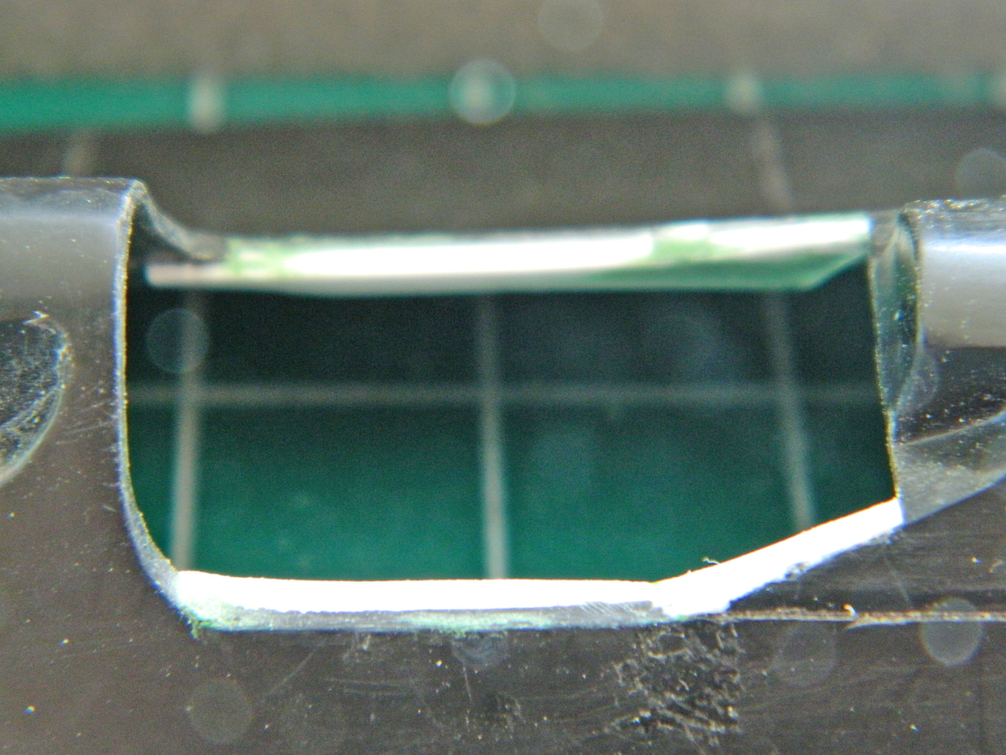
I started by penciling the outline of where the styrene has to be shaped to something less inaccurate:
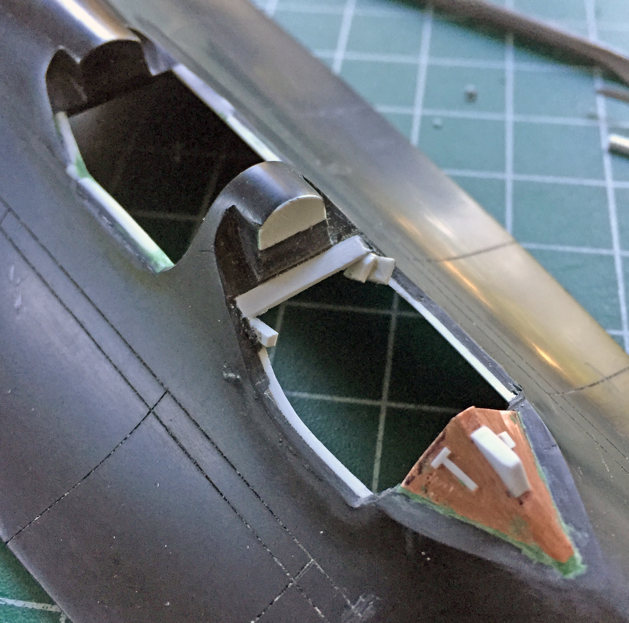
With the styrene mosaic filed/scraped/sanded to dimension, next up is getting the added styrene to its final shape and adding the details needed: