With the springs for the latches wound, I made a simplified version of the shock absorber that slides into them. I punched out a couple of discs, glued rod to one, then slid the spring down, trimmed the rod, and added the second disc:
After wrestling with the alignment of the second disc, I realized these discs don’t have to be opaque…I can use clear styrene which will make for much easier alignment. And since these things are so small, I used a piece of rolled masking tape to hold ’em while I glued the second disc on:


There is a lever that attaches to the latch that one end of the spring is attached to. I made those and added the levers and the springs:

With both latches made, they were glued together:
Then I had me some fun. When I tried to fit the assembled latches into the nose gear box, they didn’t fit. They didn’t fit by a great deal, but not fitting is not fitting. Much scratching of head, kicking of cat, being clawed by cat, wandering around muttering ensued. Once that was out of my system (temporarily), I realized that rather than modify one area/section to enable this sodding thing to fit, if I took a little off each area it just might fit in there (the alternative was major surgery in a cramped space). So file, sand, pray, dodge lighting bolts created by praying (and thereby giving away my position), fit, file, sand (avoiding prayer…I can learn), and repeat several times until the bastid just fit…but fit it did:


Whew…
Now that I have all these bits, it’s time to stuff them into place. So that these things would go in at all, it was time to add the nitrogen tanks:
Then the spaghetti panel:
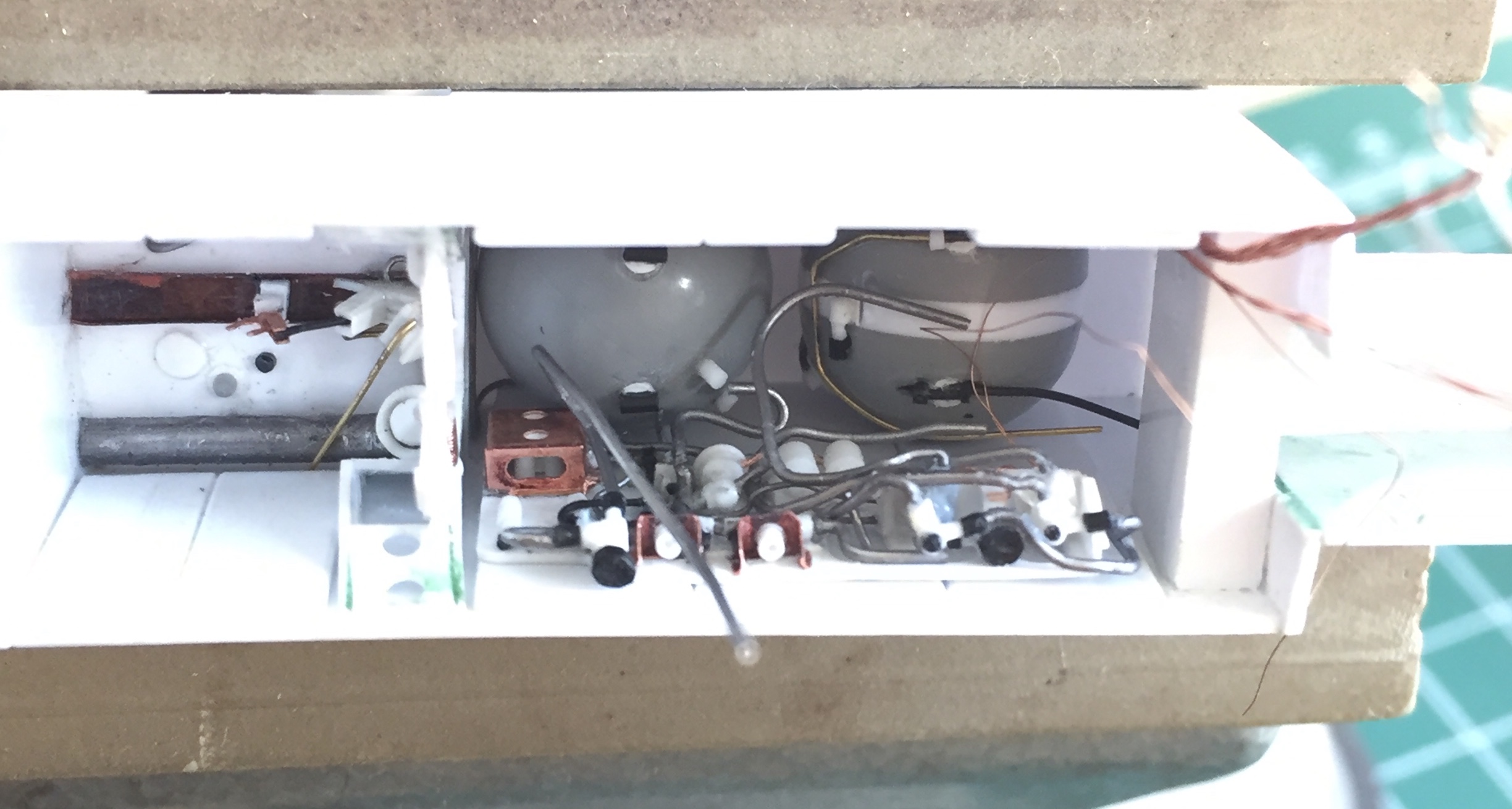
Then tie the spaghetti panel lines to the tanks:

The next step is to start scratch-building the front landing gear strut, but before I can do that, I have to wait for my new micro-lathe to arrive. Having NO shortage of things to do, I put this assembly to the side and did something else.
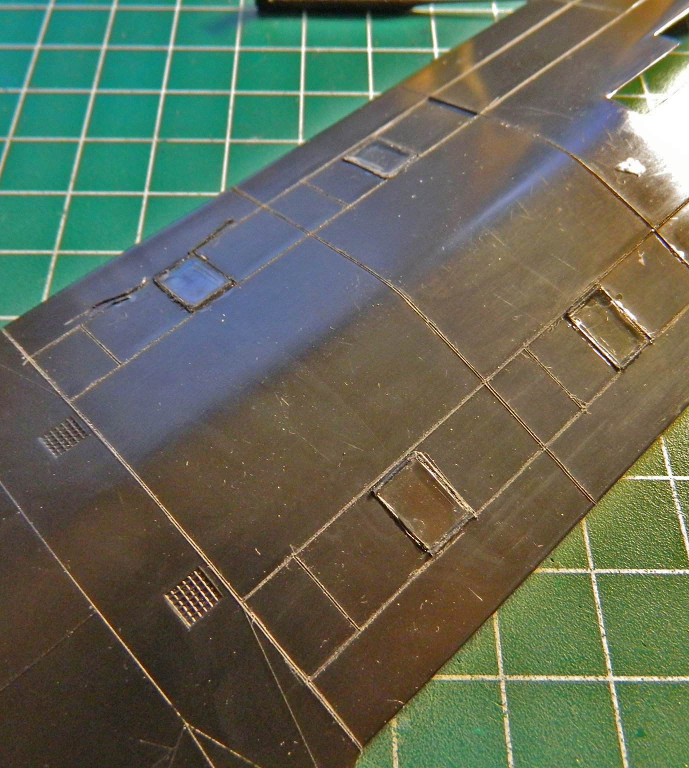
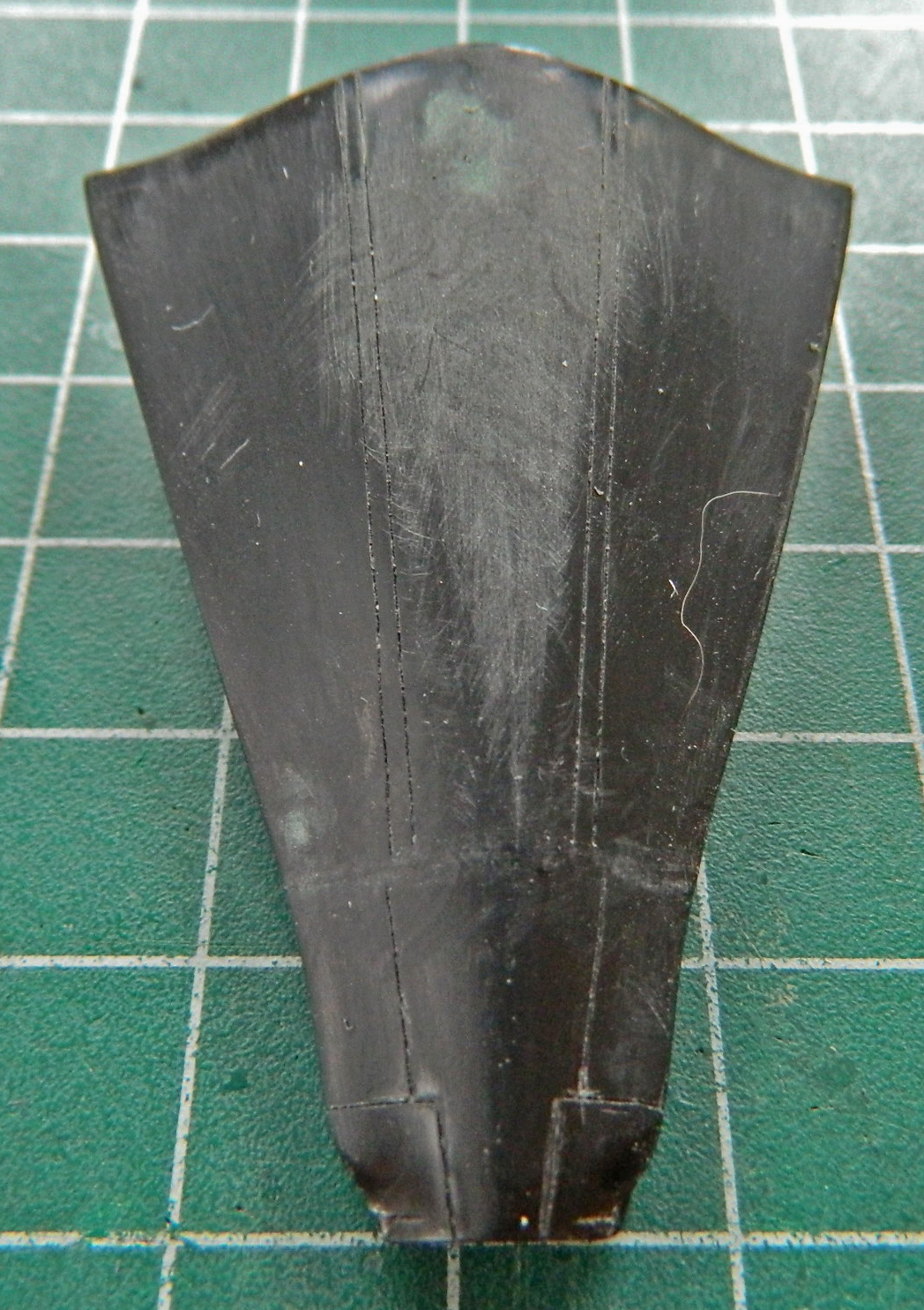
Tail #972 doesn’t have camera ports and the kit does. I used the clear ports as plugs which will get painted over. That started by gluing them into the openings and then gluing the nose halves together:
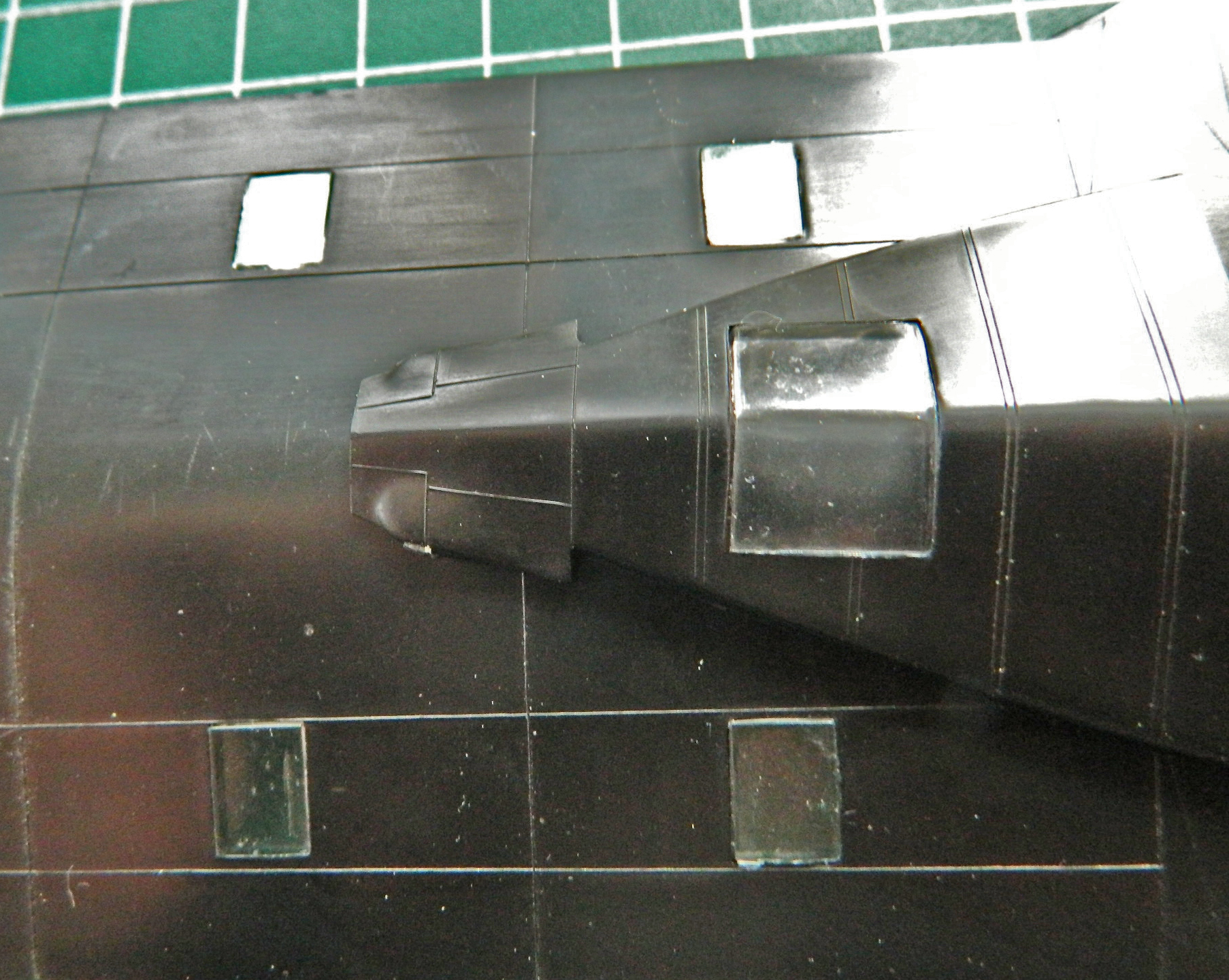
While the glue set up on the clear parts, I added sprue to the LARGE gaps between parts (evident on the right in the photo):
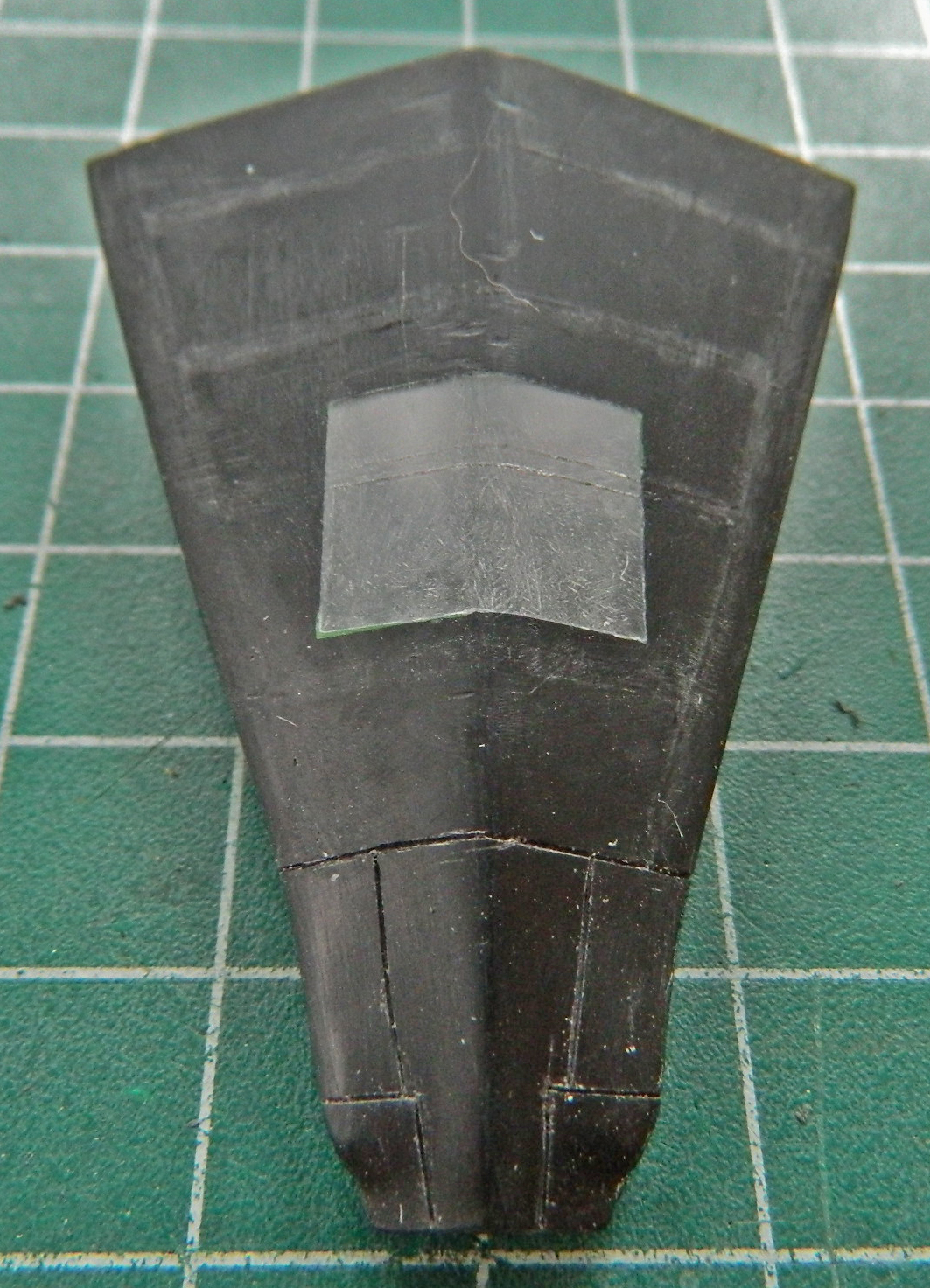
The rectangular ports are in the wrong position, even faired over. I scribed new panel lines to the left of where the kit put them:

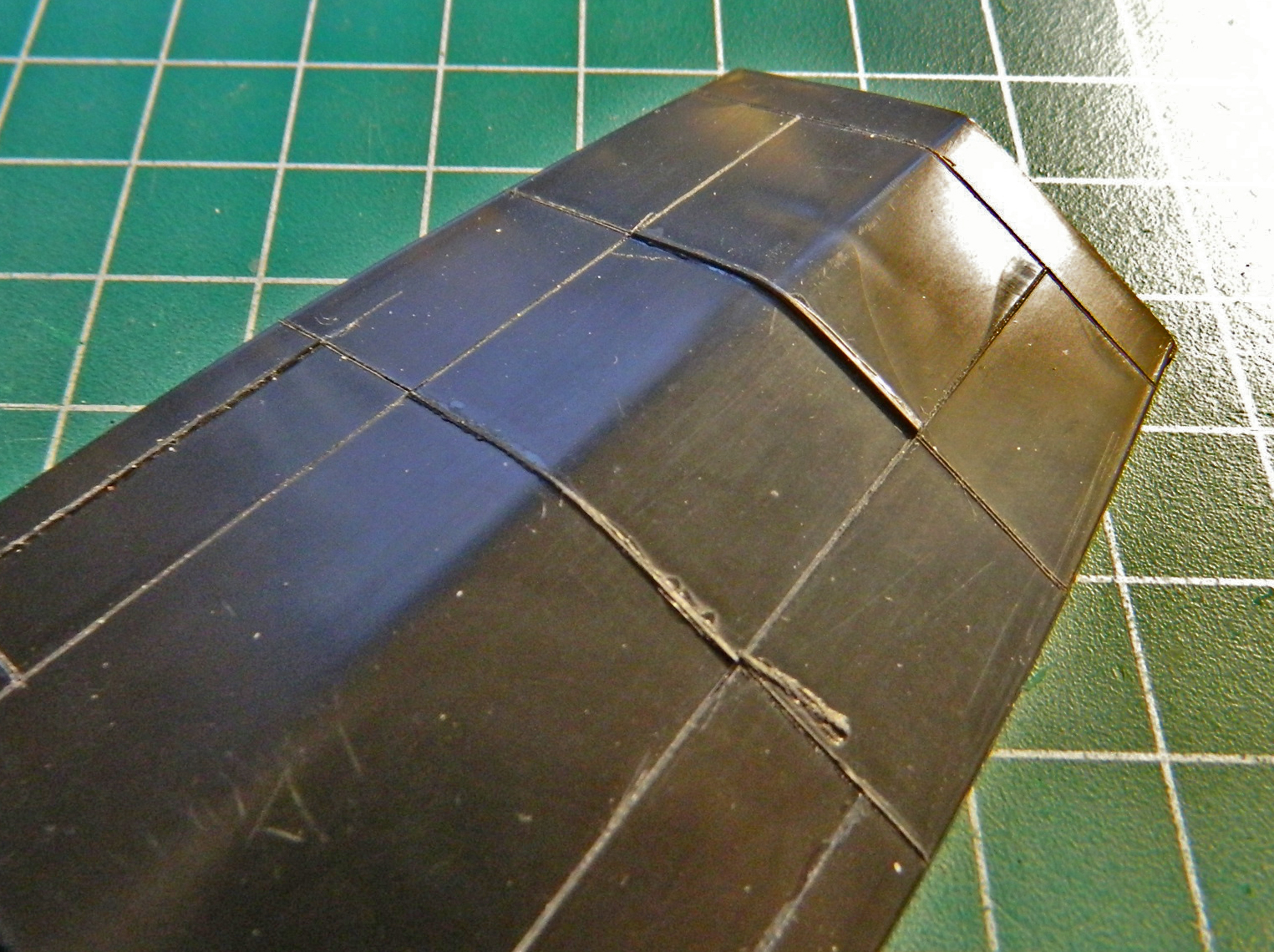
Since there was to be a lot, A LOT, of sanding to this area, and I was going to have to do it anyway, I screwed up my courage (or the bravado that passes for courage) and started scribing panel lines:

There are probably those out there who just scribe, re-scribe, and add scribed panel lines as a matter of course. I ain’t one of ’em. Since I really am so poor at this aspect of modeling, I take my damned, sweet, time with it. And even THEN there are numerous oh-goddamit moments where the scriber (in this case usually needle) skips and adds a groove where I don’t want a groove…which then needs to be filled. If I get lucky, the oh-goddamit groove isn’t where I have to scribe over it. In that case, I can just add putty. If I do need to scribe over it, then I have to add sprue. Adding sprue means I have to let it sit overnight before trying to work it. Rushing it results in the scriber running into plastic that’s still gooey and that leads to more oh-goddamit moments…and tasks.
So there I am, merrily (merrily?!) scribing away. Pity I didn’t check references first. Some of the panel lines are in the wrong places (which of course I scribed in before noticing that). So I added sprue in several places as well as puttying the oh-goddamits and gaps between the clear part and the rest of the nose:

While that was all curing, I flipped the nose over and scribed lines and filled in large sink areas with putty (as well as filling a TOTALLY blown panel line with sprue):
Then I went and watched snow melt while the glued sprue cured.
Back at it the next day, I noticed that the panel lines under the nose where the big camera window would be was flat out wrong. So all of that got filled with sprue:
While those areas were curing, I sanded the top of the nose:
Then next day I filed/sanded down the sprue:
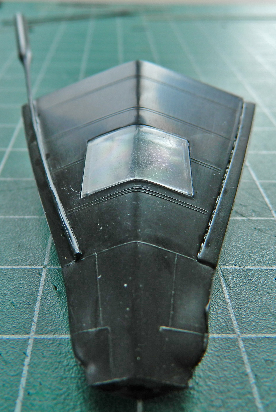
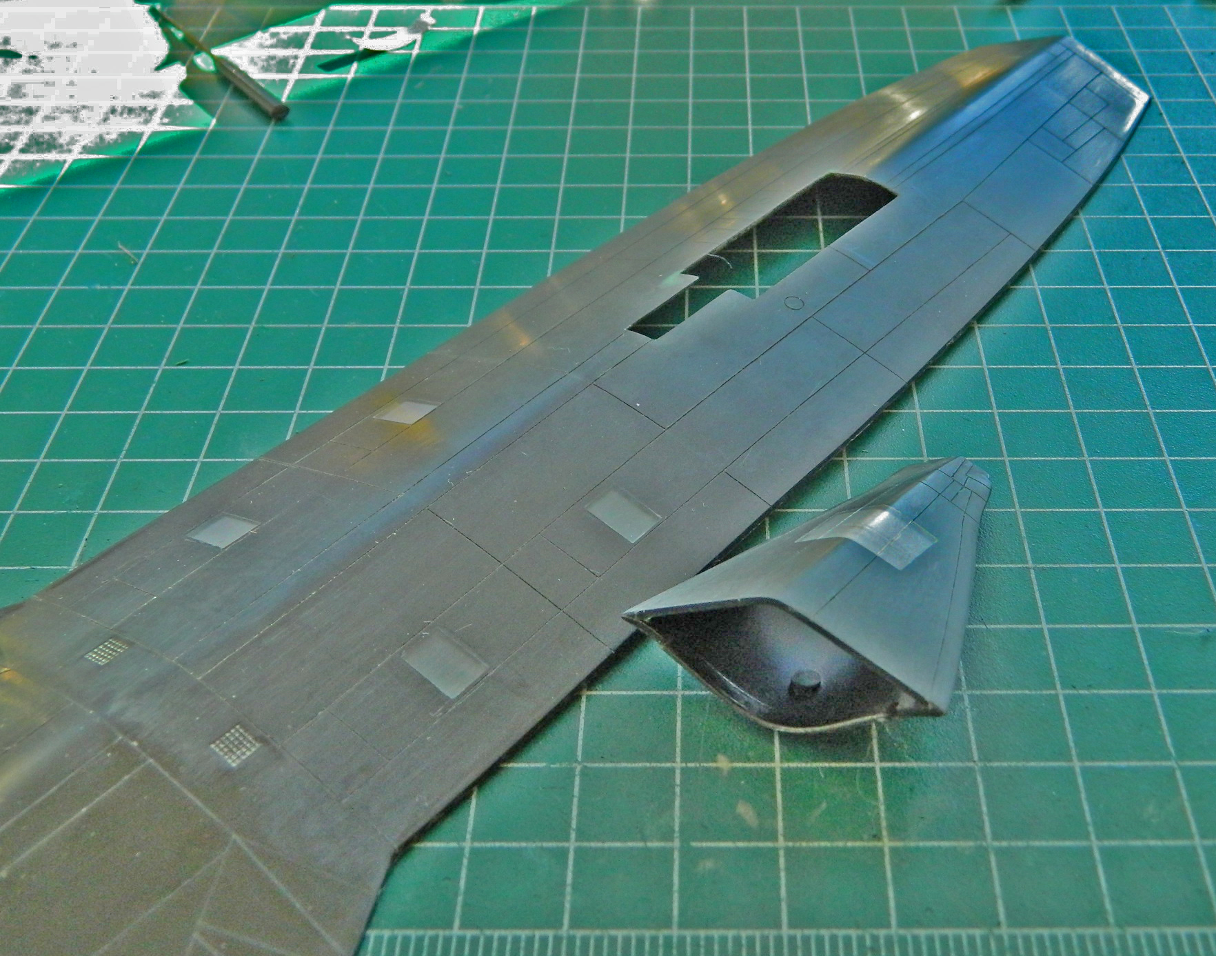
Finally (which is actually a joke…”for now” is probably more accurate) checking references, I saw where missing panel lines had to be added, incorrect panel lines filled, so I started that and found a conundrum. Nothing is quite lining up! Yeah…these two lines go here. And they’re supposed to line up with this part of the nose gear bay opening. So why don’t they line up?!
They don’t line up because when the dies for these molds were cut, someone was either having a very bad day or the supervisor had an apprentice make the cuts. They don’t line up because the ENTIRE opening is about 1/8″ (3.18mm) to 3/16″ (4.76mm) of an inch TOO FAR TO THE RIGHT! The [DELETED INVECTIVE] is off center. The tape added to the fuselage section is centered to the wide end of the opening:
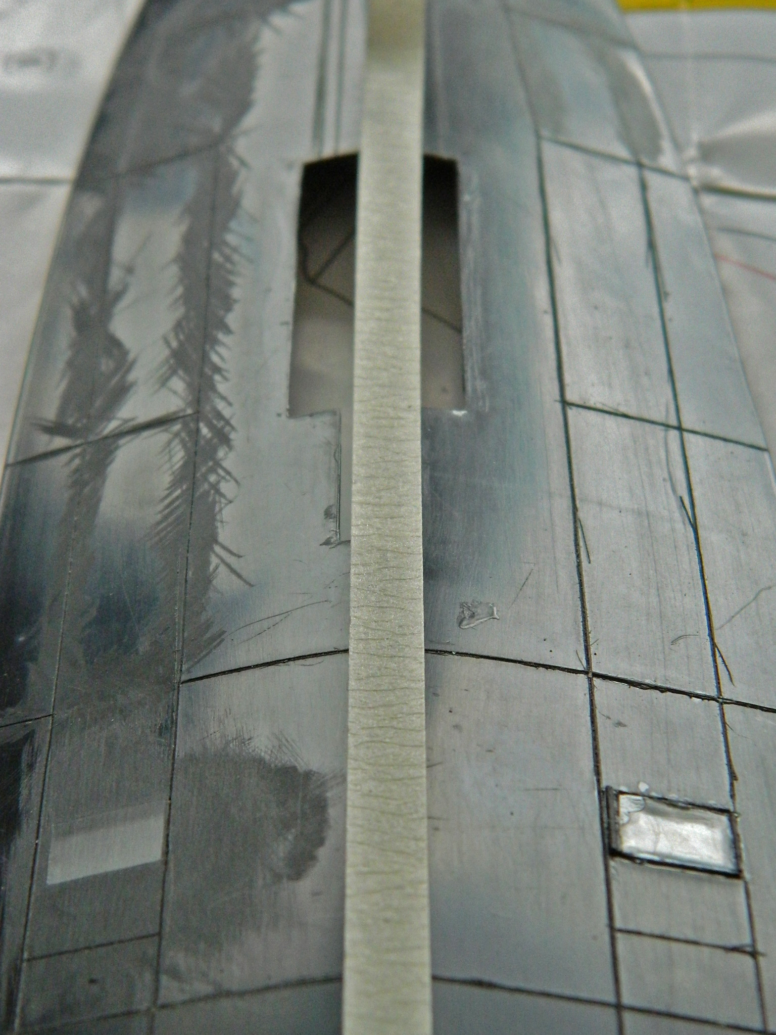
All sorts of depraved fantasies traipsed through my mind, not the least of which was to reposition the opening. Uhm…NO. No, no, NO, no, no!! The landing gear box I made is dimensioned to this opening in this position and to relocate the opening means making a new landing gear box! Y’know…I think I’ll pass on that one. It means I have to jigger a few things that come next, which means they won’t be entirely accurate, but I think my 90-95% mandate covers this.
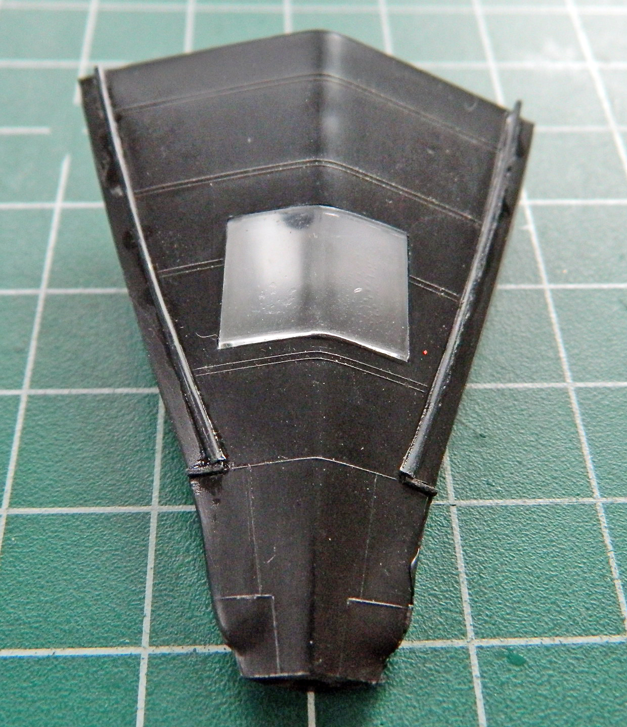
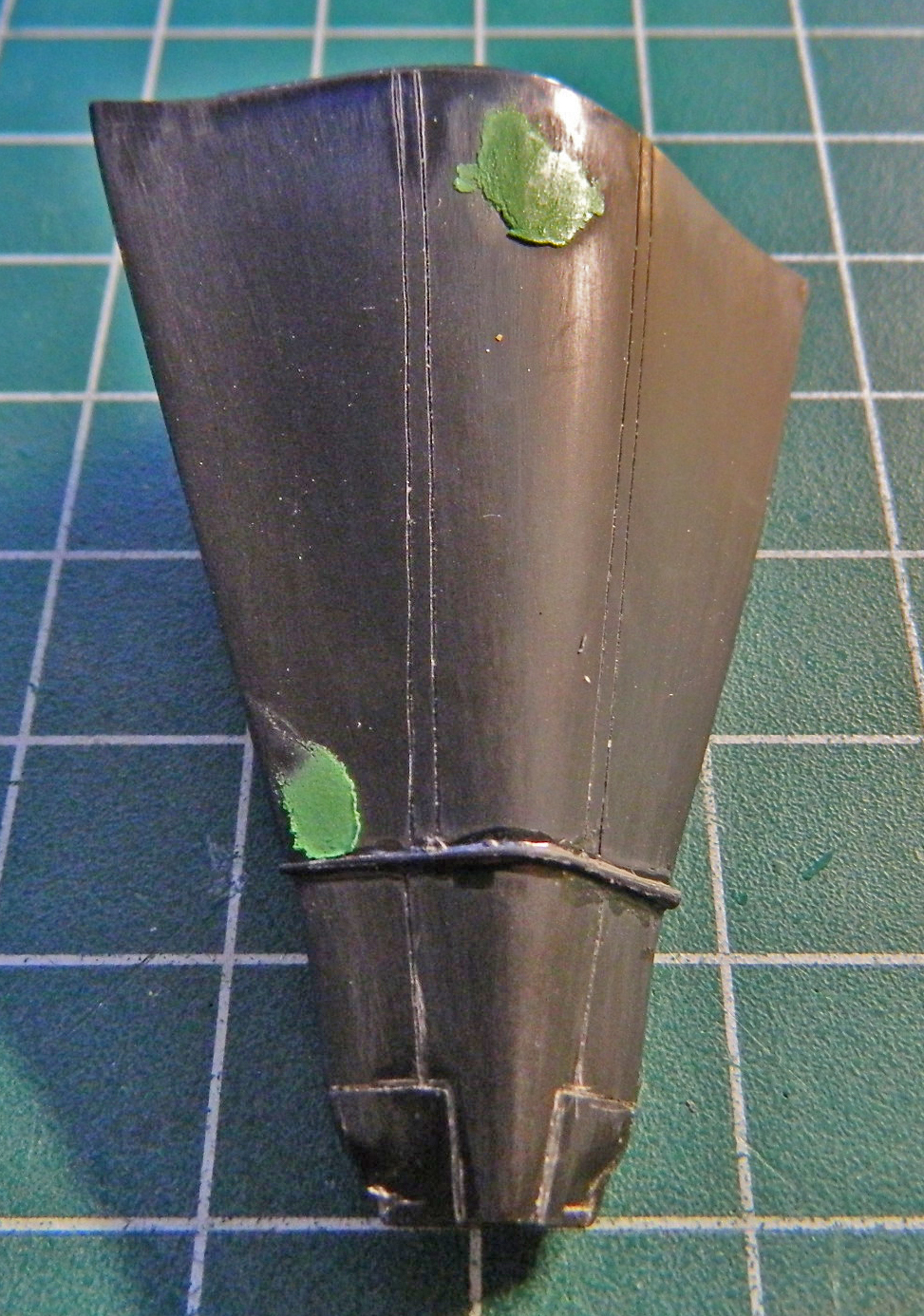
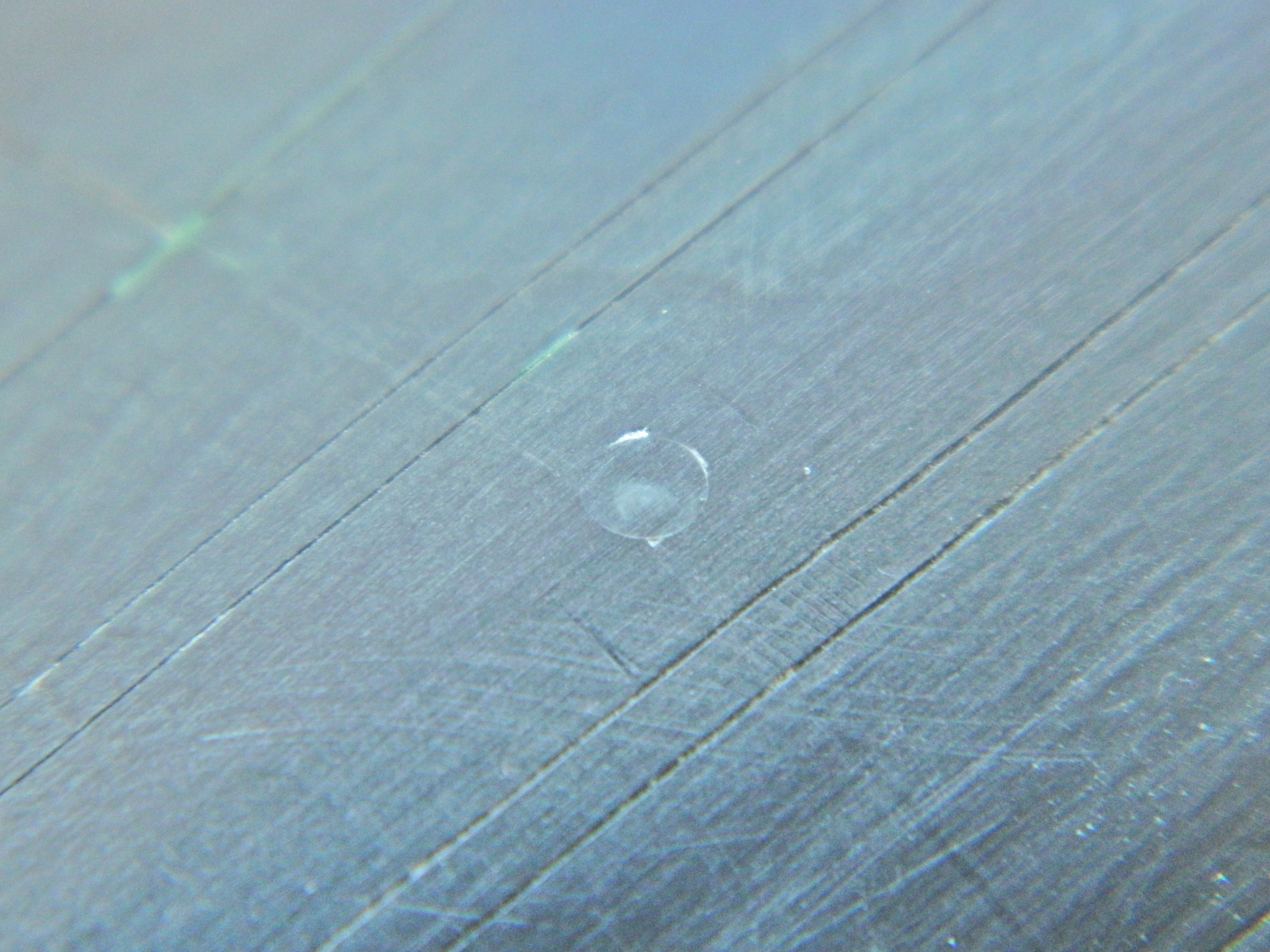
One of the things that had to be jiggered is a sensor port in the belly that the kit didn’t model. It’s supposed to be centered between the panel lines I had to add, and sit right on the center line of the belly. Yeah. Well, it’s gonna be one or the other…unless I put this port just a little off center. I realized that if I centered the port, it would be off center of the scribed lines. That misalignment is more obvious than the port being off center of the fuselage. Right…centered to the lines it will be. Mostly.
It started by drilling a small pilot hole. I took a section of clear sprue and chucked it into a variable speed drill set on LOW speed, and used files, emery boards, and sandpaper to reduce the sprue’s diameter slightly. I decided which drill bit to use relative to the diameter of the sprue and widened the hole in the fuselage. While I still had the sprue in the drill, I used a smaller bit to replicate the detail in this area, then stuffed the sprue into the hole, glued it from the inside of the fuselage, and started trimming, filing, sanding, and polishing:

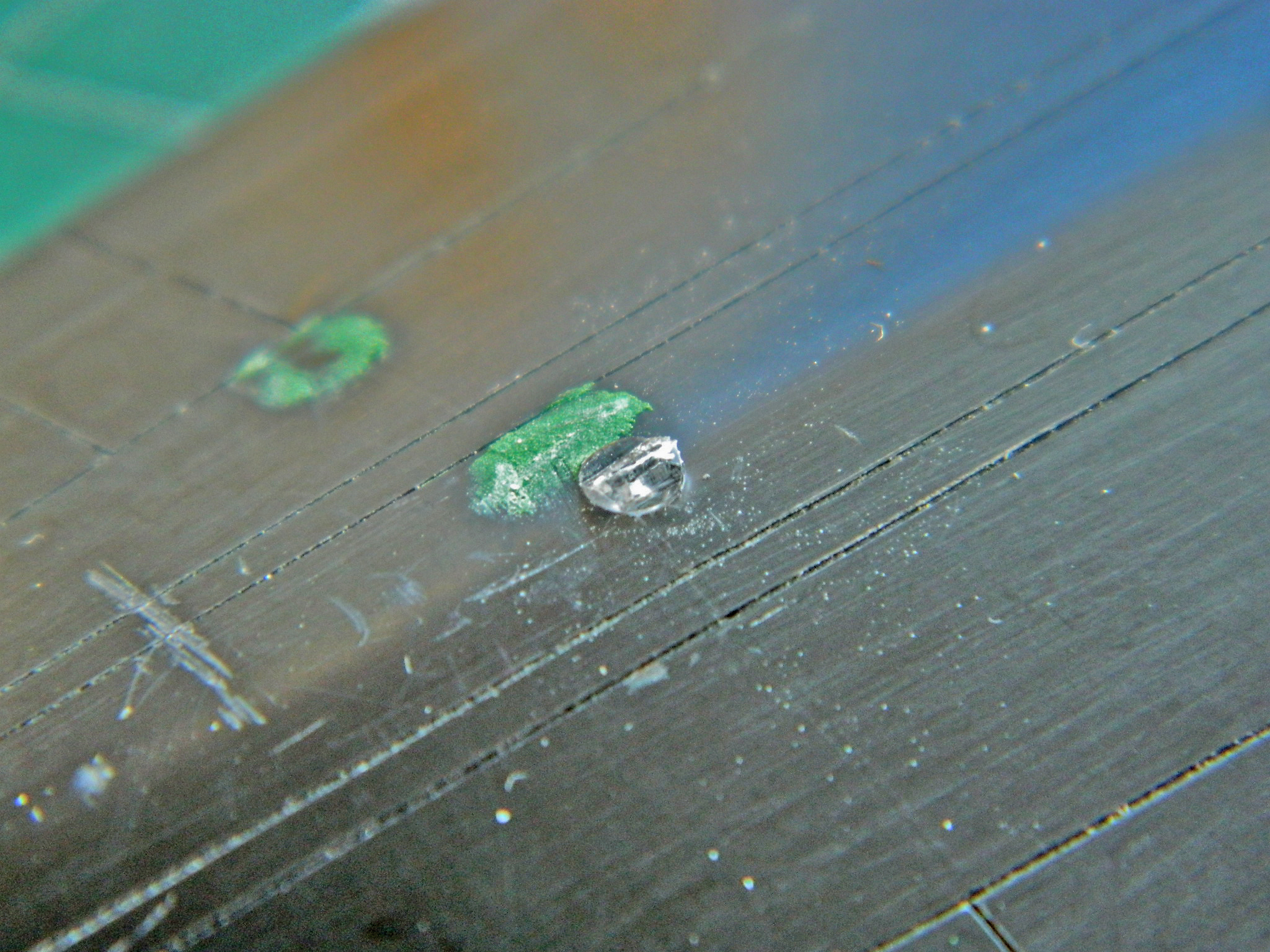

I back-painted the sensor using three parts Tamiya’s Chrome Silver (X-11) and one part Tamiya’s Flat Yellow (XF-3) for the surround and Tamiya’s Flat Black (XF-1) for the center:
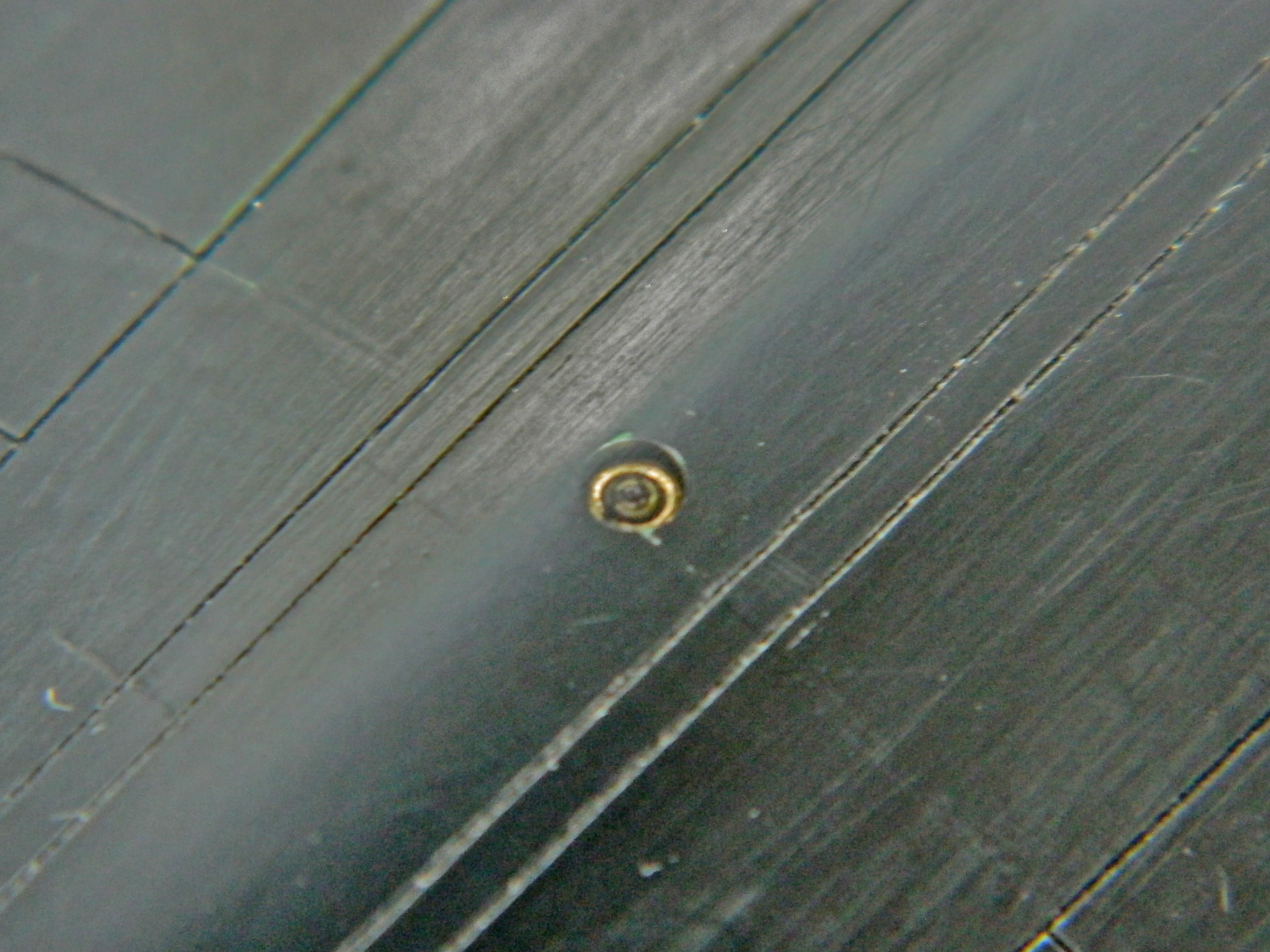
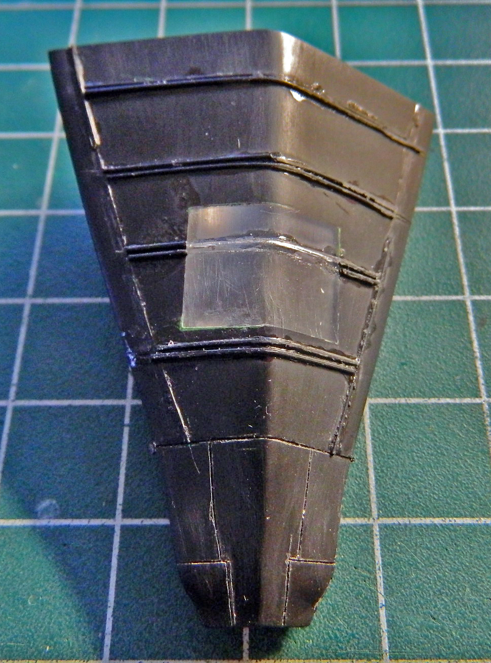
Several days of chasing oh-goddamits, scribing, RE-scribing, deepening scribed lines, sanding, puttying, sanding some more, and finally this section is done (I think):
And as I was wrapping this up (I think), I got a notice that the micro-lathe I ordered from Grizzly Tools (part #G0745) arrived! Oh goodie…more insanity on the docket!

Hey love the build I haven’t read from the beginning but I have read sections great build. Question what source did you use for panel lines ?
LikeLike
Thanks for the kind words, Alex. I’ve used a few sources, mostly photos…some from online, some from magazines. Last June I went to the Smithsonian National Air Space Museum to take some reference photos of tail #972 (which is the particular Blackbird I’m modeling) and a took a metric butt-load of photos. So I’ve been able to figure out (I HOPE!) what’s accurate for this air-frame.
LikeLike
Hi !
I’m currently working on this. Do you have references pictures to share, specially yours ! Here in France, SR-71 is just a well-kown plane but never-seen too 😉
LikeLike
Greetings, Florent!
I compliment you on your English; I speak no French and lacking ANY facility for language, I’m impressed by those who have that ability.
I will shortly compile a LOT of photos and send them via email. Look for an email from “TrampRoyale.”
LikeLike