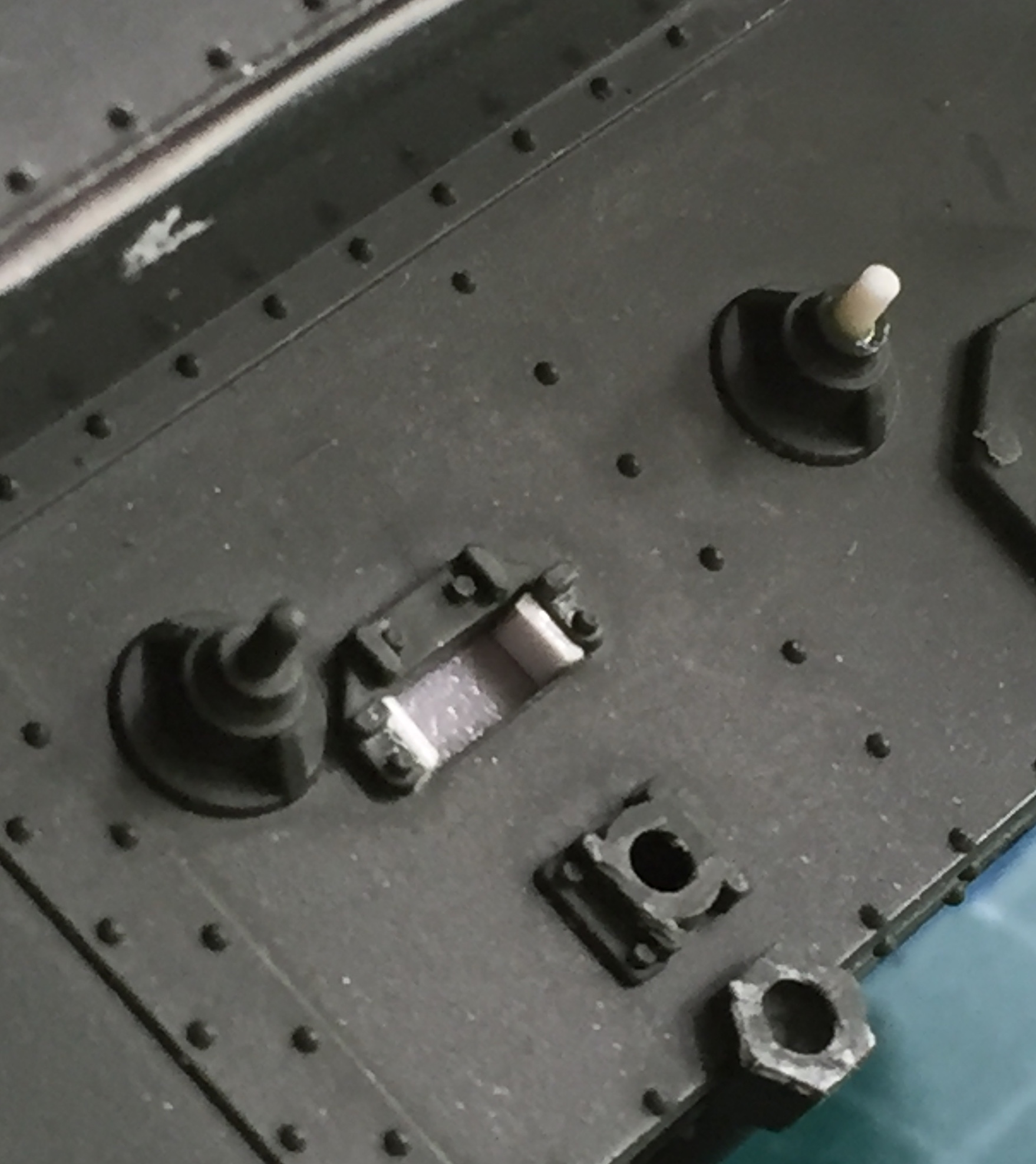
I installed a piece of plastic under the rear of the upper hull to block off the interior and then used Tamiya TS-6 Matte Black rattle-can to paint that section. I also painted some things that needed to be flat white:
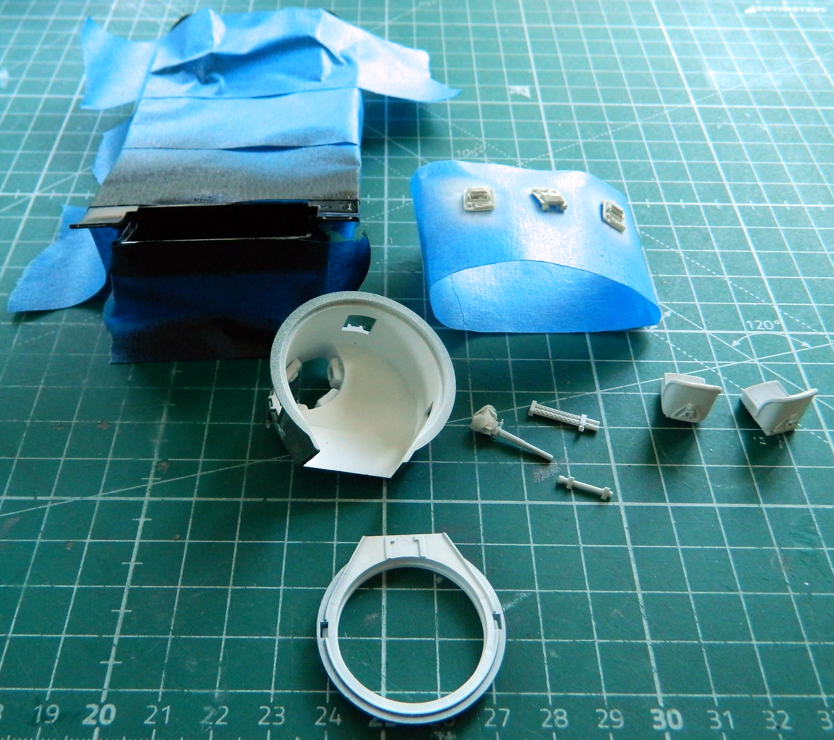
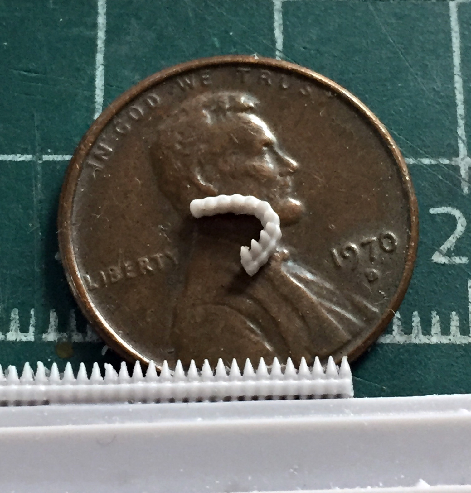
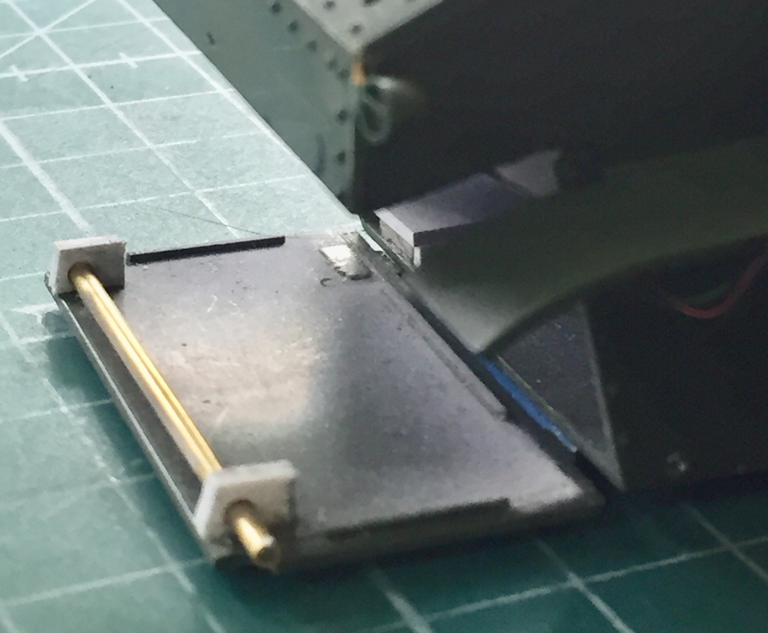
The operating mechanism for the M3’s pistol port hatches needs to be built as well, so I started trimming some .010″ (.254mm) scrap for that:
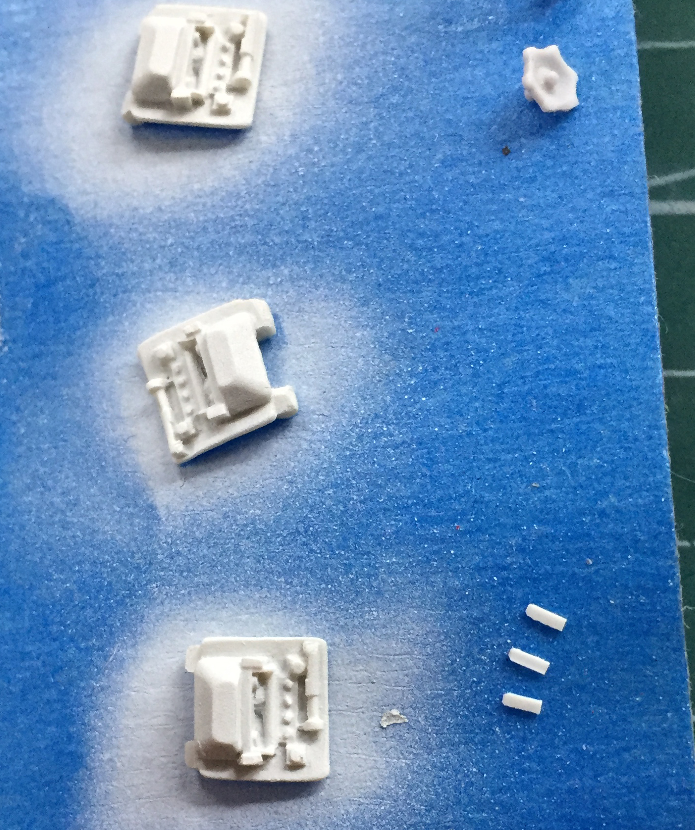
These parts aren’t very big:

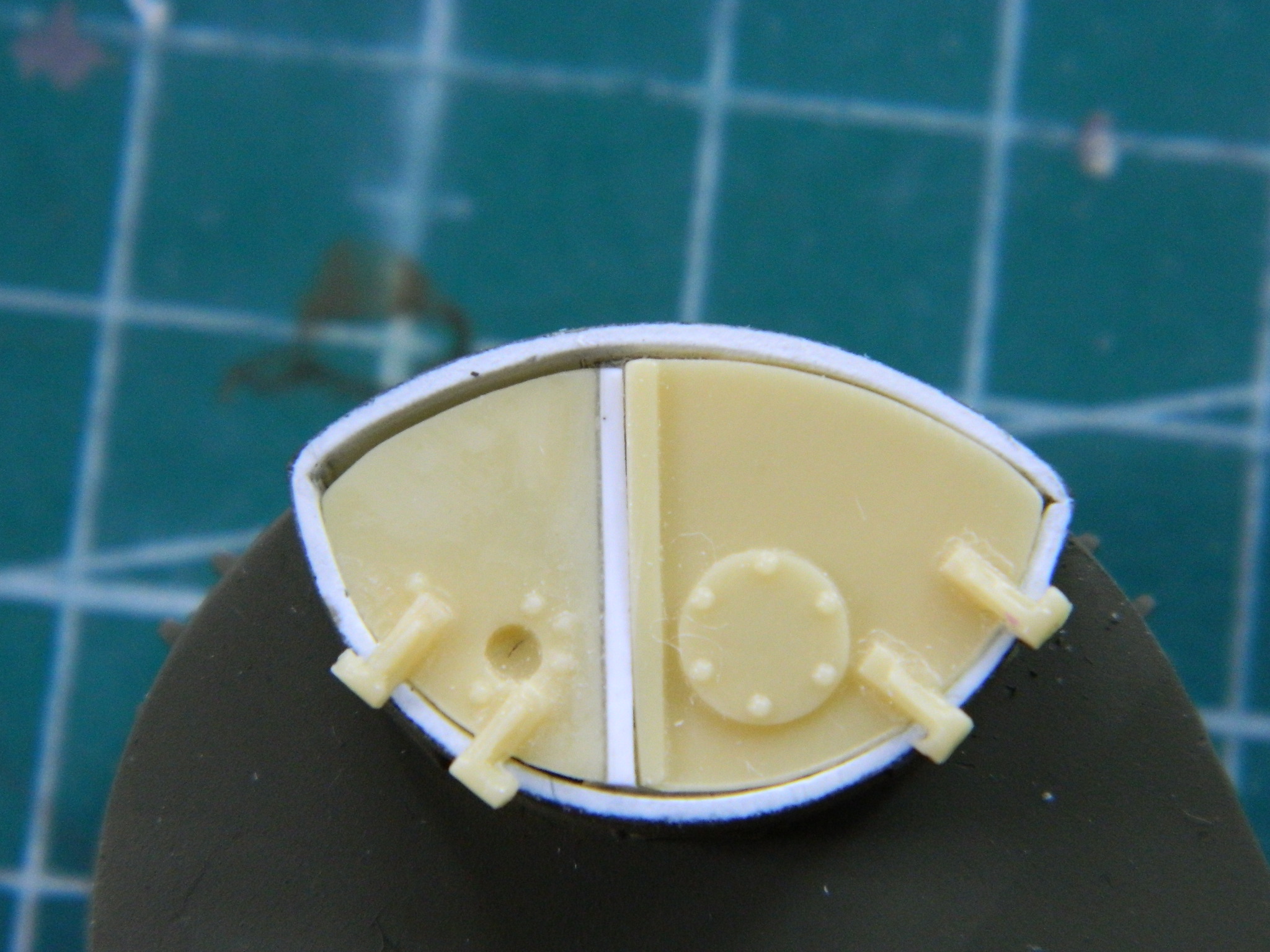
The aftermarket resin set was intended to be used with the earlier turrets that had flat sides either riveted (D37812) or welded (D38976). I’m using the “horseshoe” turret (D39273) that has curved sides. This means that some of the turret parts will need to be adjusted accordingly. This example is of the map case:
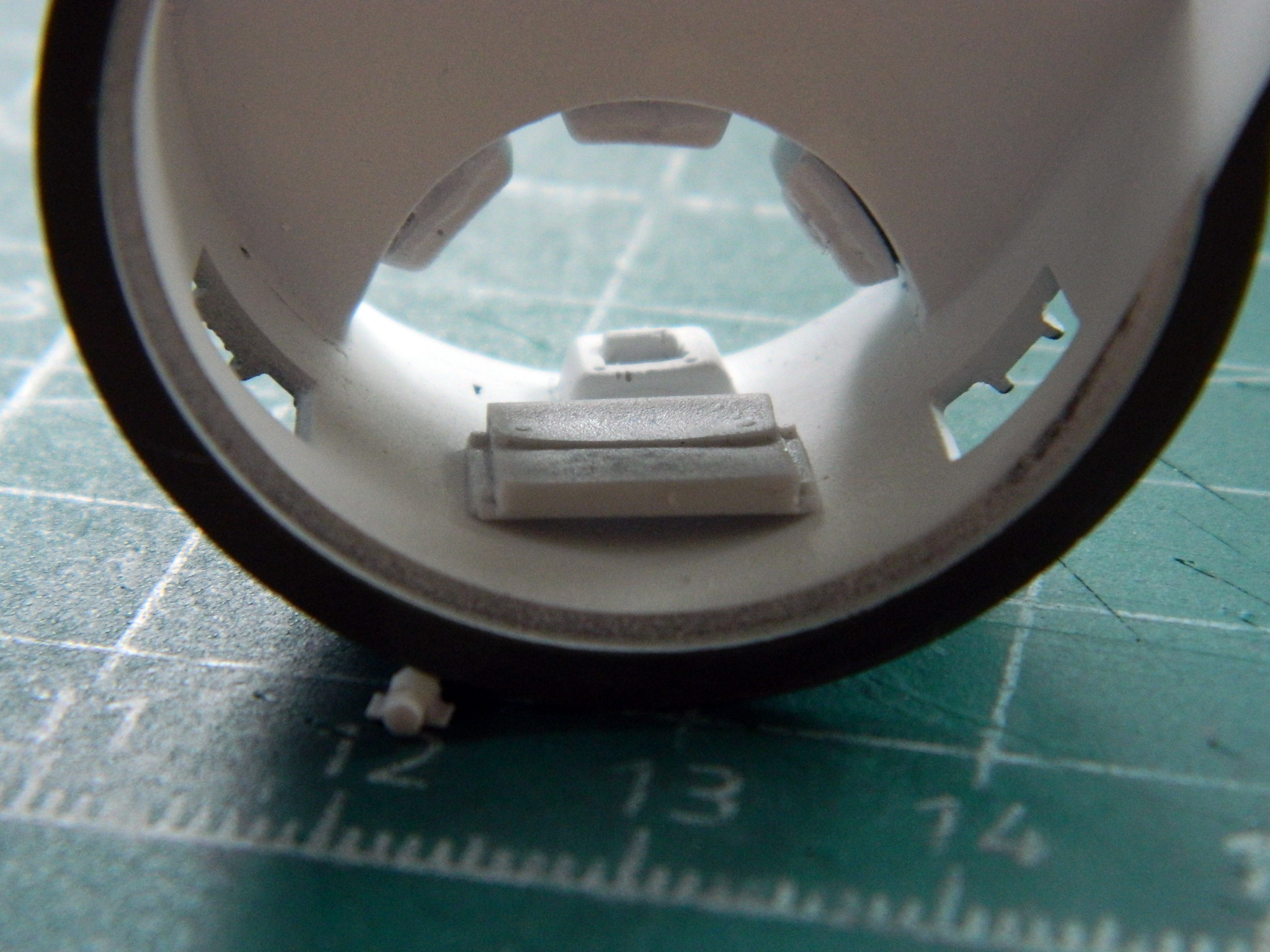
This isn’t the first time I’ve used Tiger Model Design’s (TMD) parts. They’re well made and nicely cast. What’s surprising me this time is the fit isn’t very good. This isn’t the first time during this build that I’ve found myself having to adjust things to make some sort of fit. This example is of the driveshaft cover. It’s simply too short. If I used it as it was produced, I would not have enough room to fit what must go in there (and forget what I’d like to put in there because those won’t fit). Note the gaps on either end of the cover; that’s how much more room I needed:

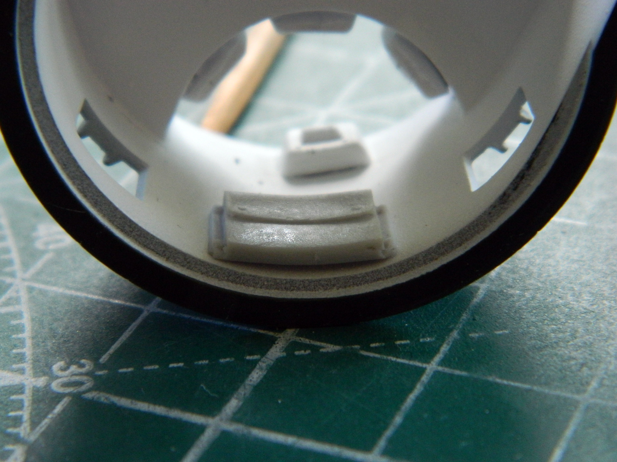
For this size/scale, that’s just too far off, which required me to add .060″ (1.524mm) styrene sheet to both ends of the cover:
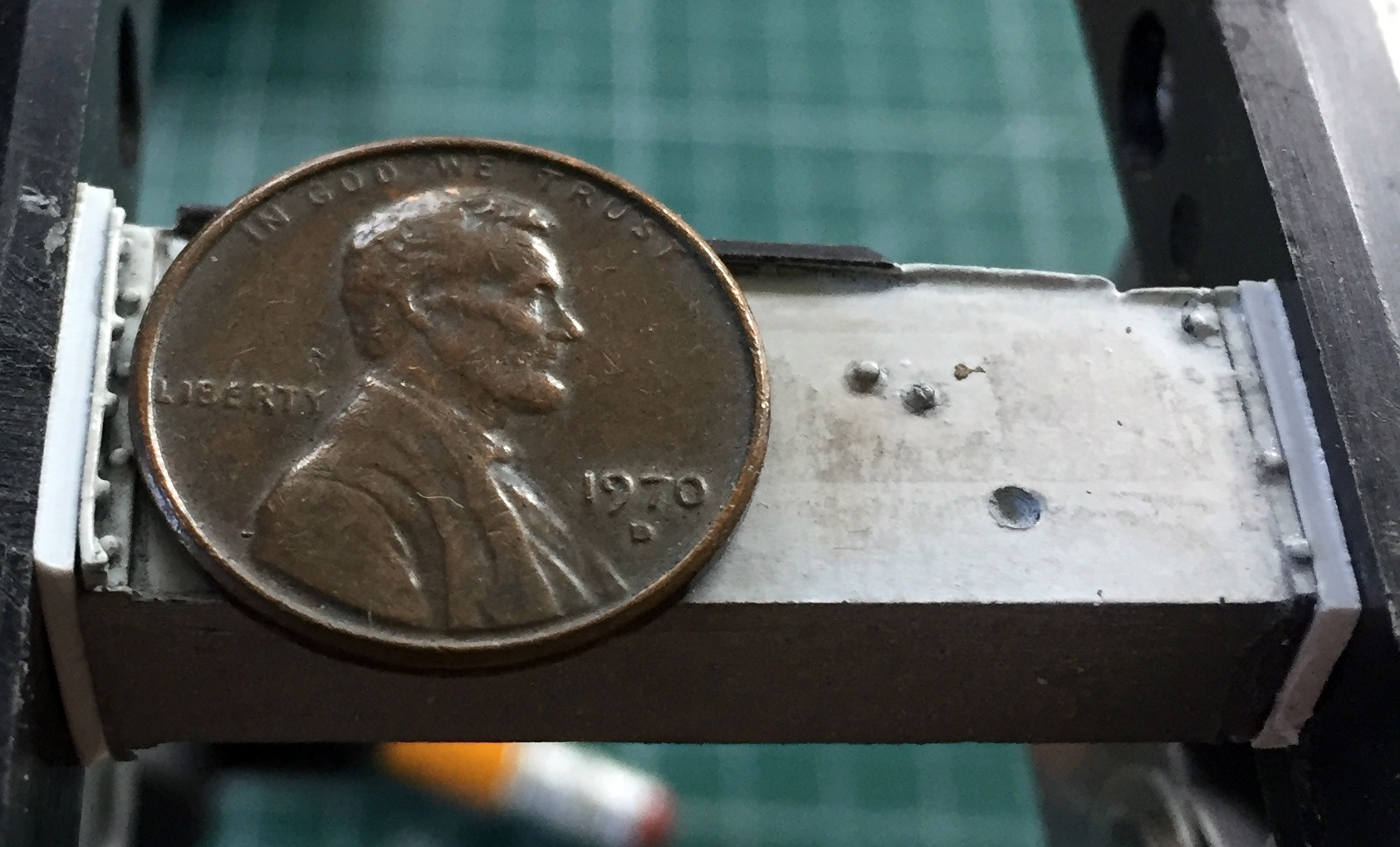
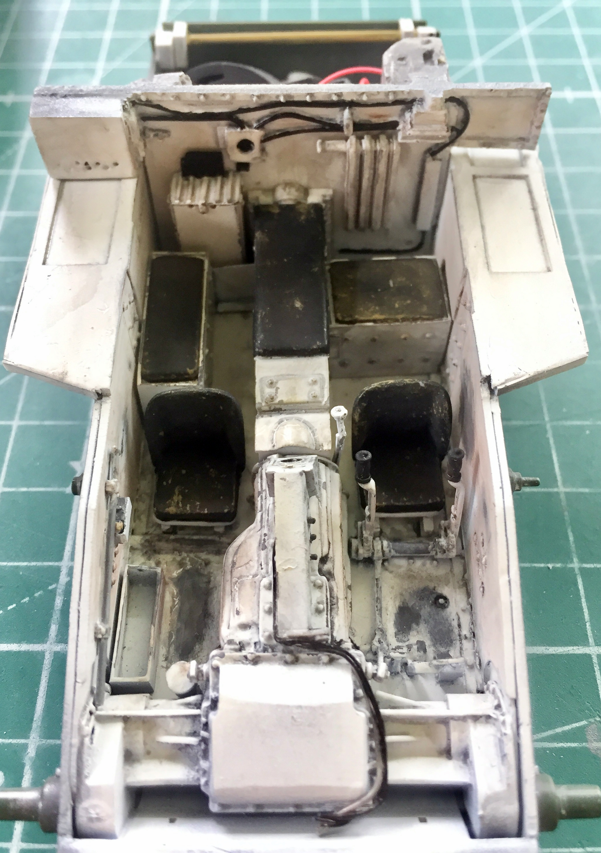
It fit better after that (the ammo stowage boxes are shown here without the pads that go on top of them to create the only seats the commander, on the right in the photo, and the gunner, on the left in the photo, have) as dry-fitting showed:
With the length of the driveshaft cover adjusted, putty was added to the additions. That needed to be sanded smooth and the paint and stains needed to be touched up:

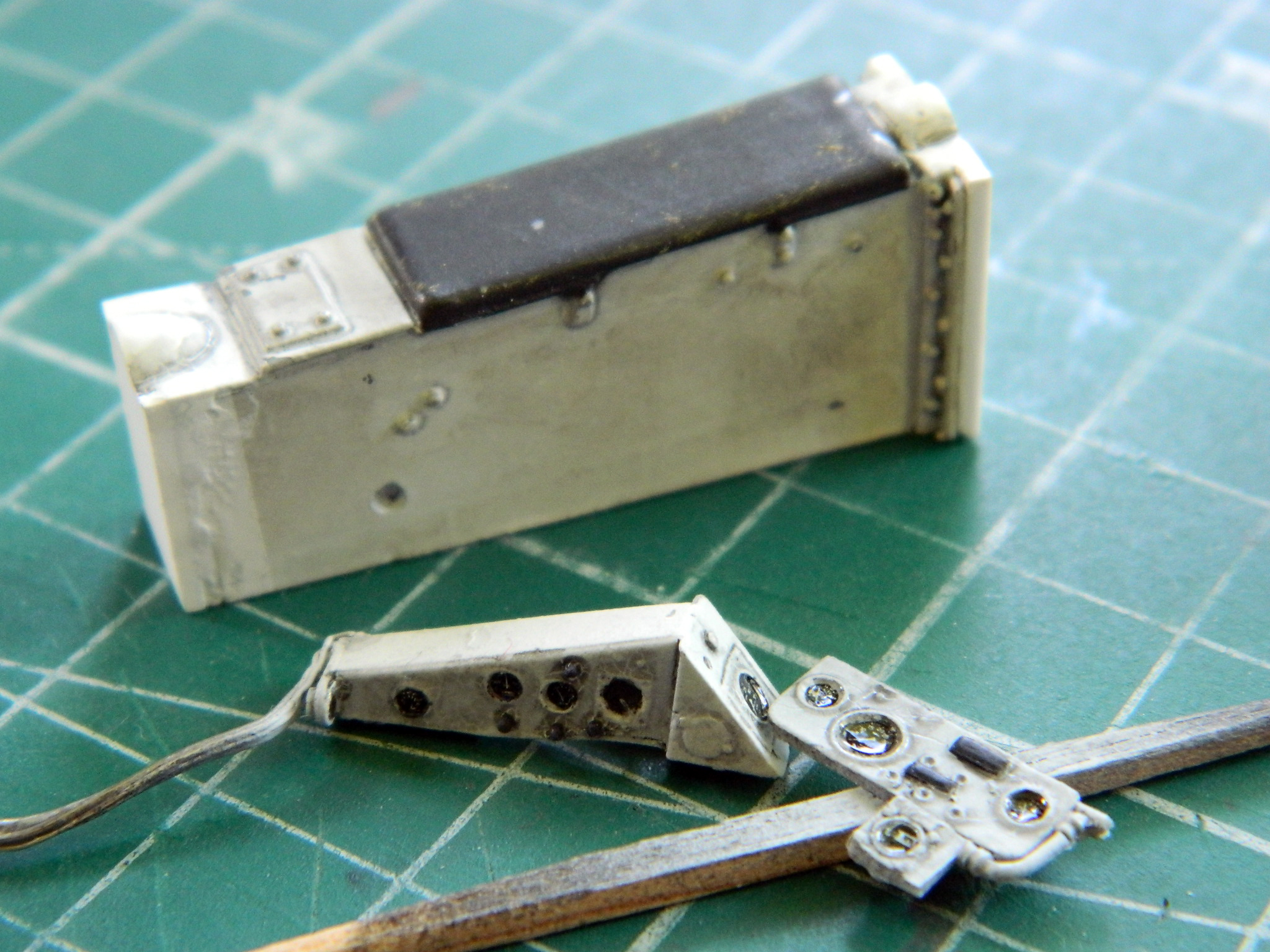
While I had the airbrush loaded with flat white, I also did the instrument panels. Once the instrument panels were painted, I added the instrument faces using Archer’s “U.S. Gauges and Interior Stencils,” #AR352098. I just wish these old eyes, even with magnification, could see better so the transfers were more centered:
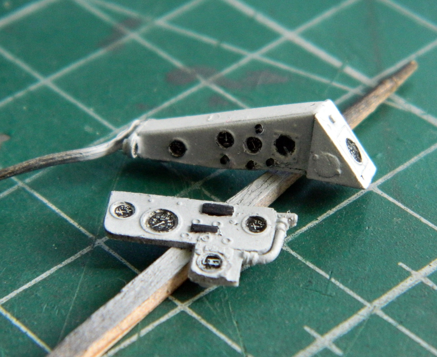
Having gotten the panels as well as I could, clear gloss was added for the dark wash to sit on, then clear matte was laid down:
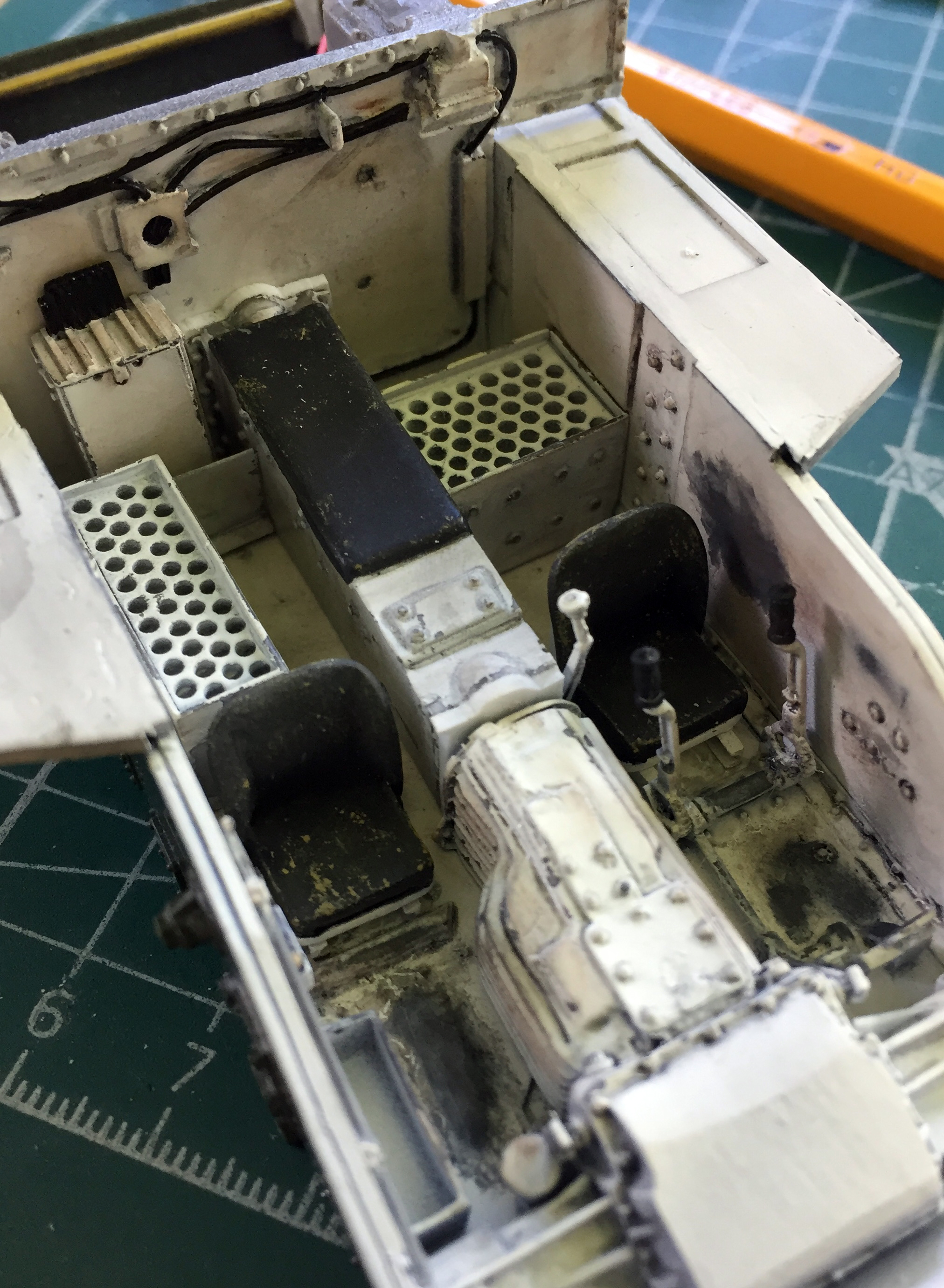
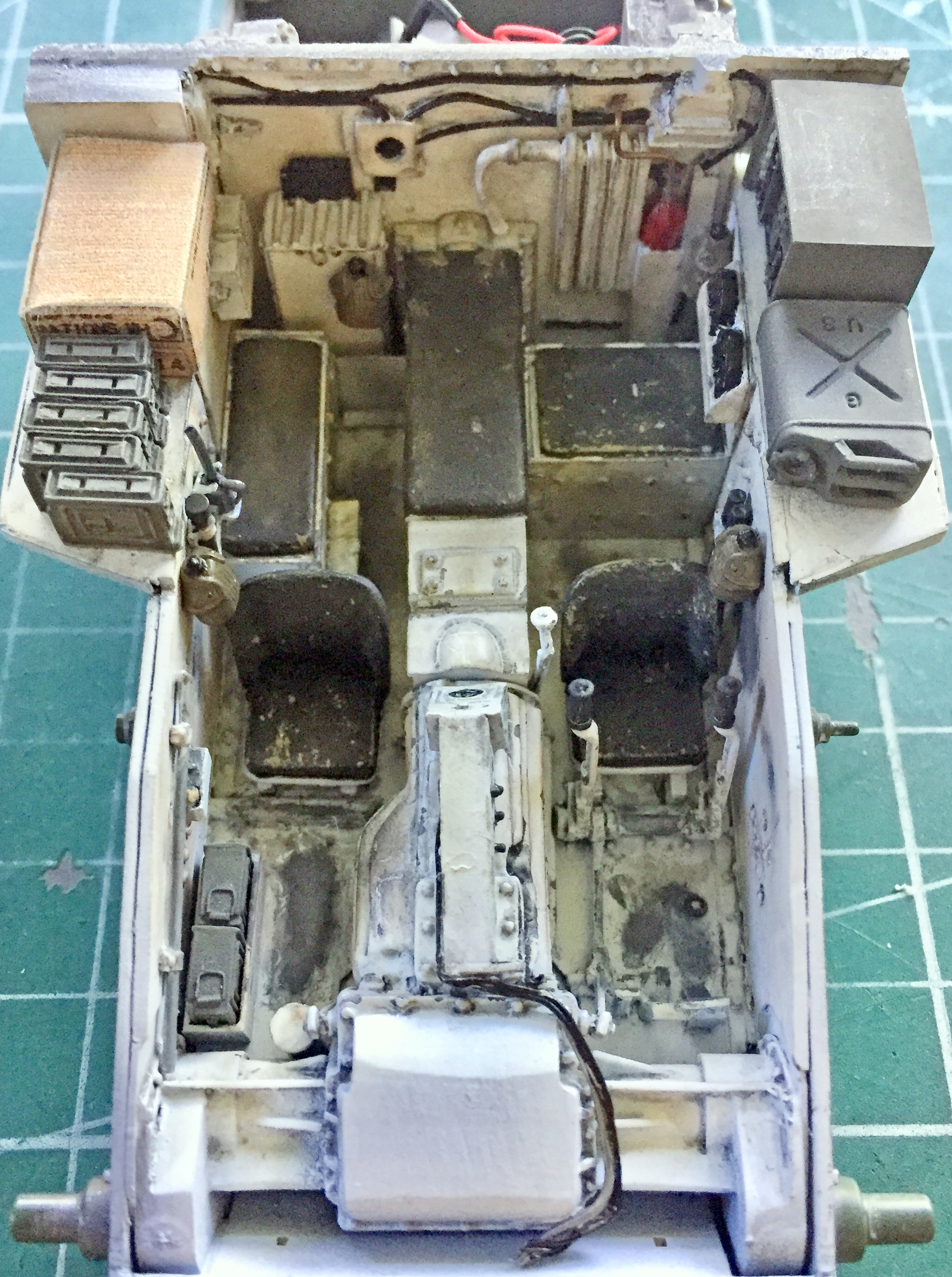
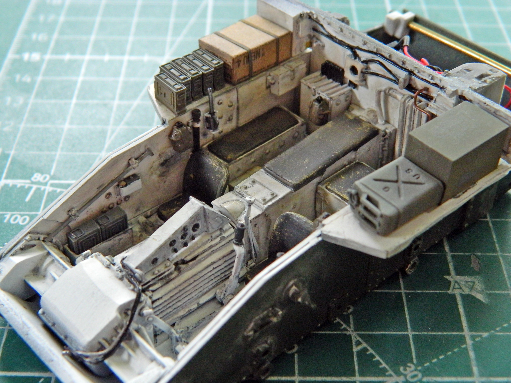
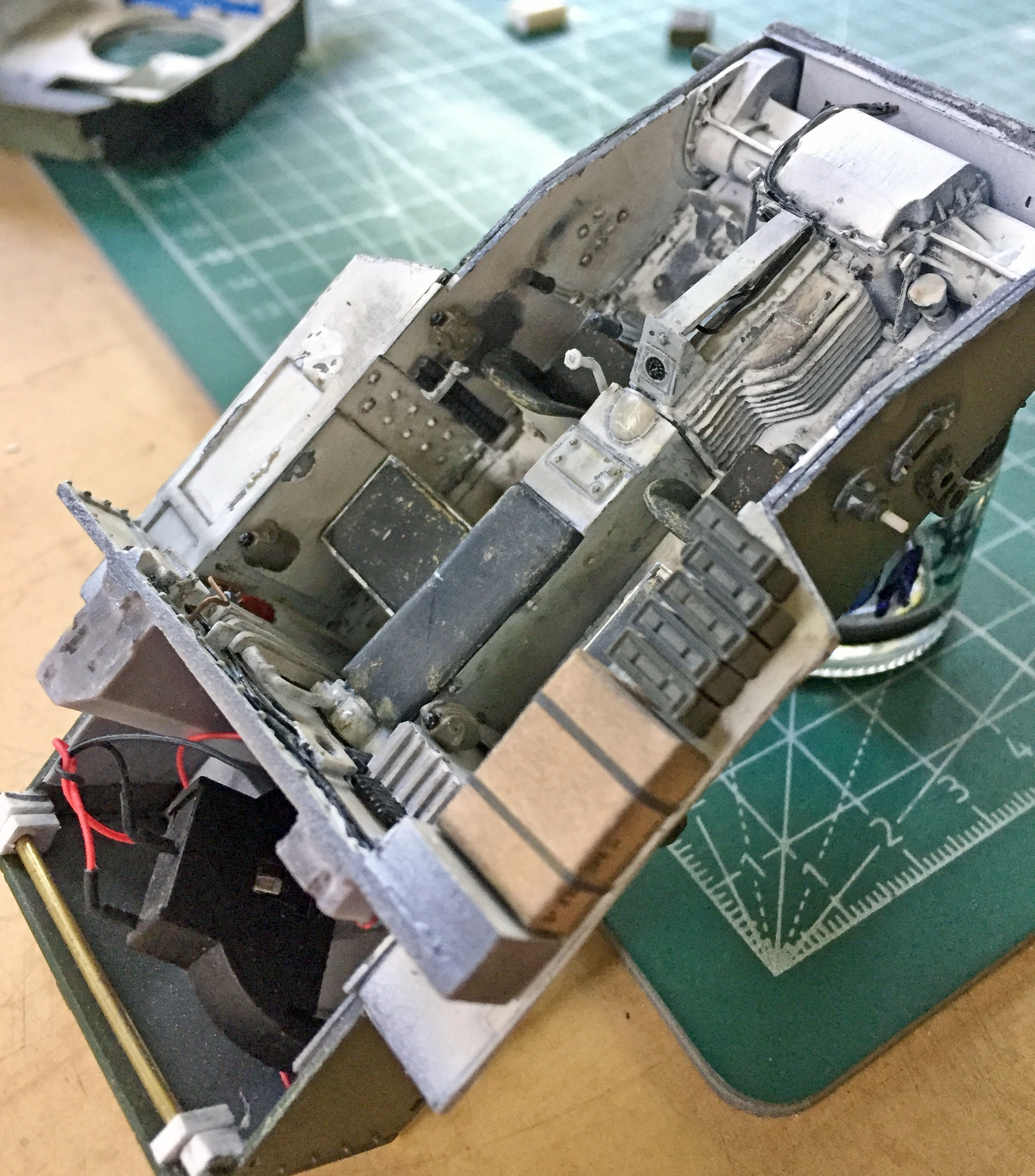
With the length of the driveshaft cover corrected, it was time to start populating the interior (note the cushions on top of the ammo stowage bins):
The rear bulkhead hasn’t been glued into place yet. The fire suppression system needed to be painted and added and the copper feed line (using copper wire) needed to be added:

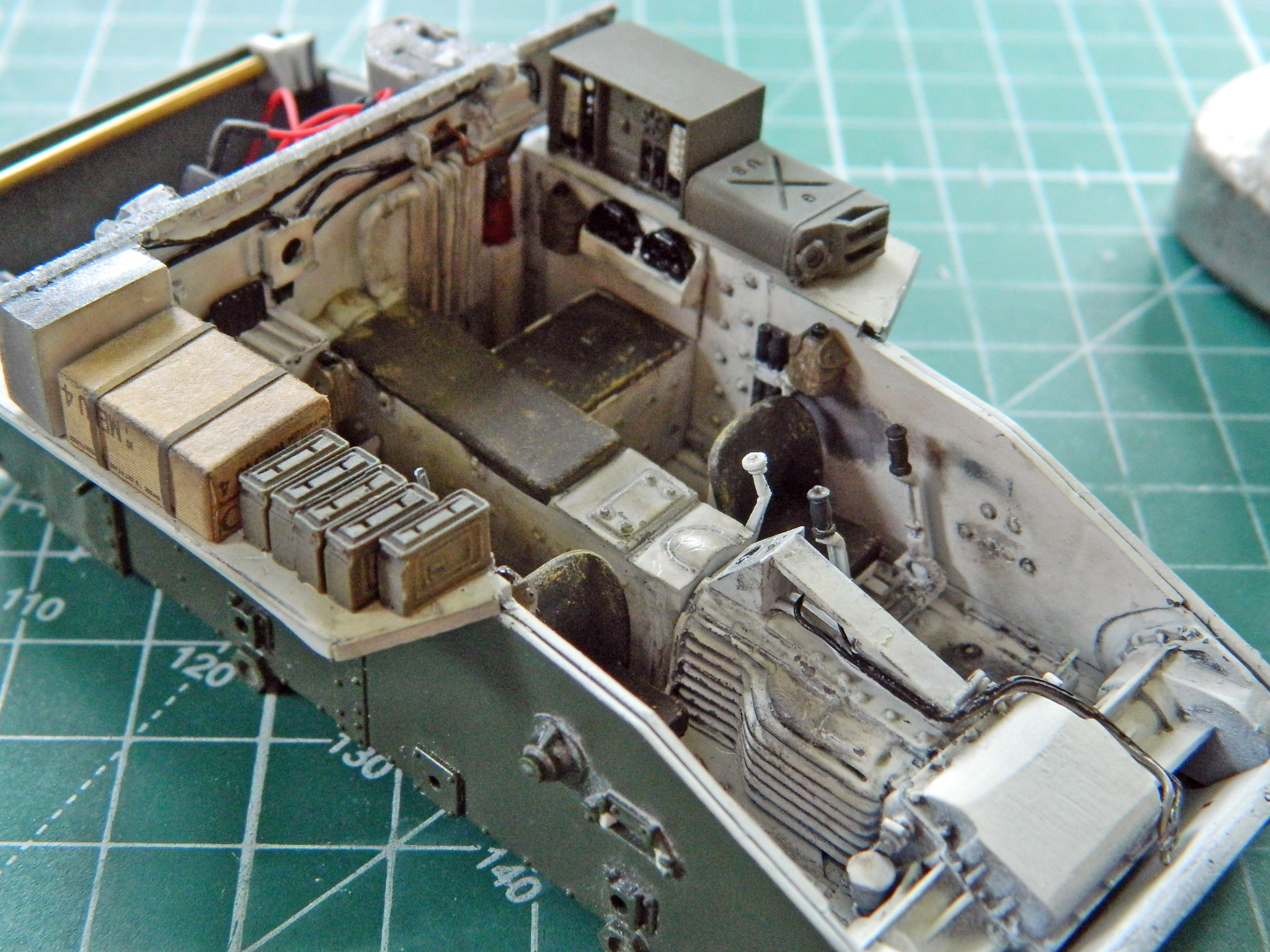
With that in place, the bulkhead and center instrument panel were glued into position and other small items (Thompson submachine gun drum magazines, spare main gun sight behind the bow gunner, and spare .30 caliber (7.62mm) machine gun barrels behind the driver) were added and things were dirtied up and chipped:

More things were added including the radio, C-ration box (a Verlinden item…I’m gonna miss that guy), canteens, and so forth:
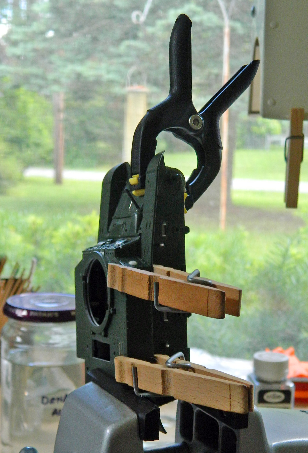
Something I’ve been itching to do was to check the LED light and see how it looks:

Yeah. That works just as I’d hoped it would.
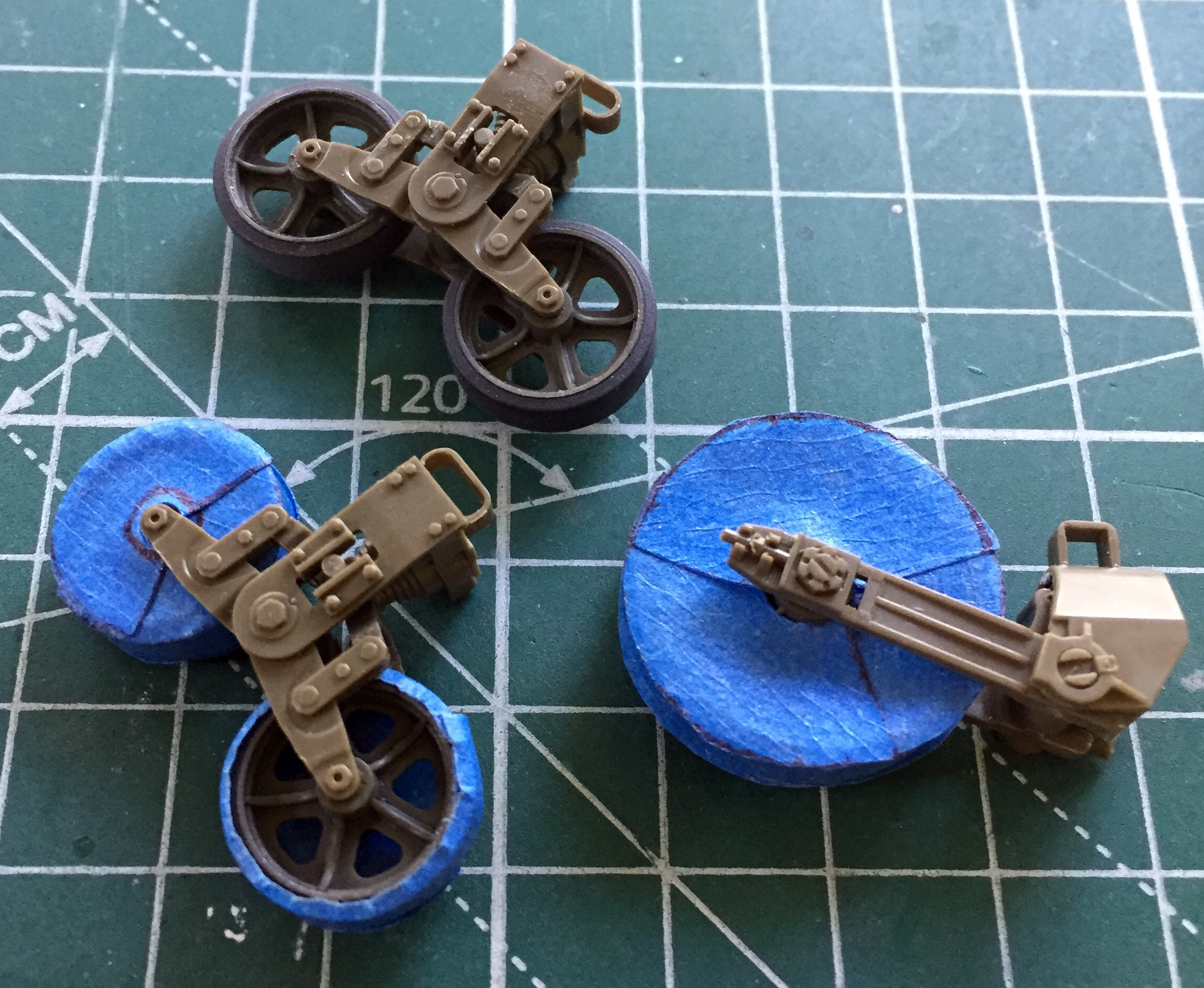
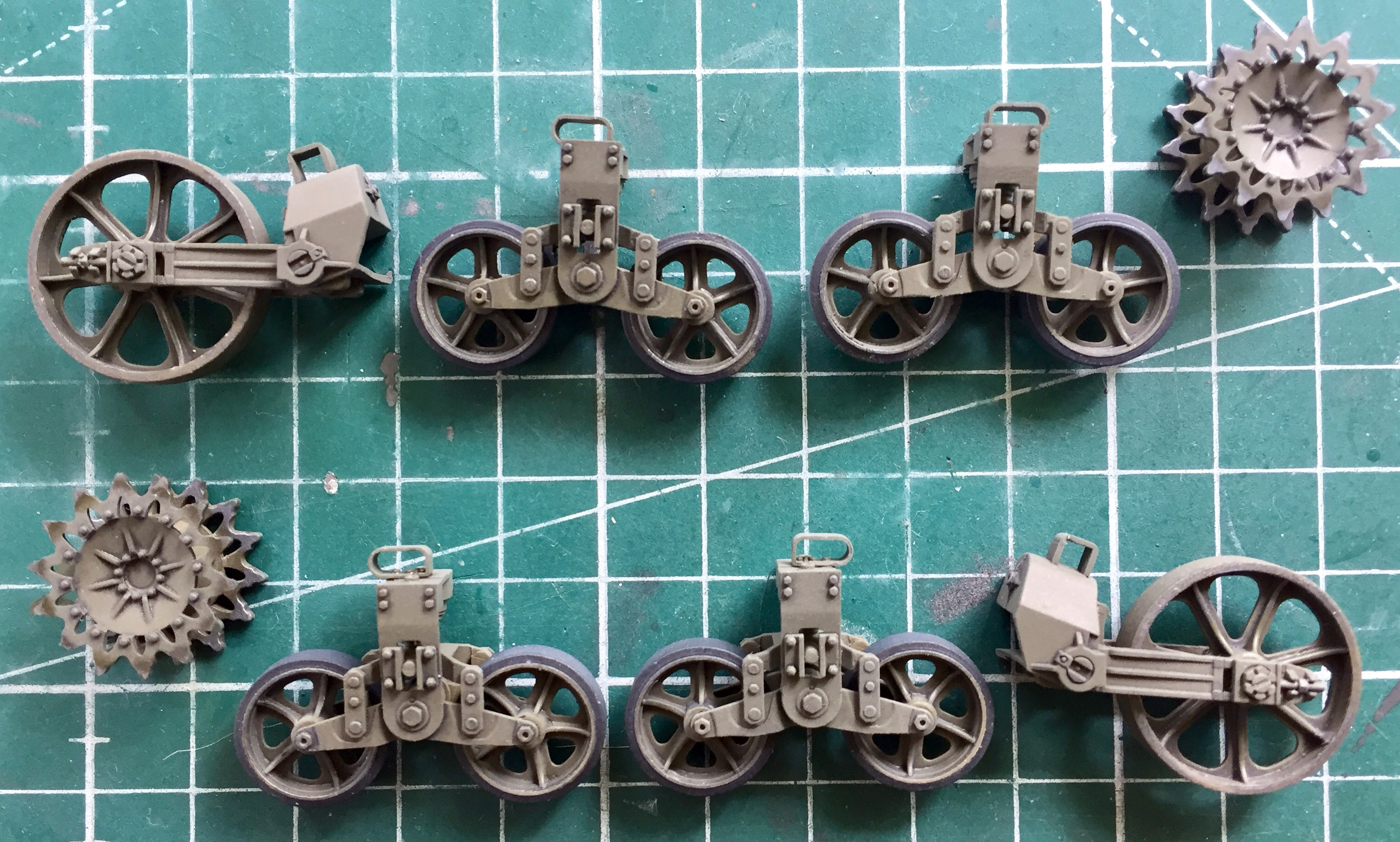
Then I assembled the AFV’s suspension, adding a little putty where needed:

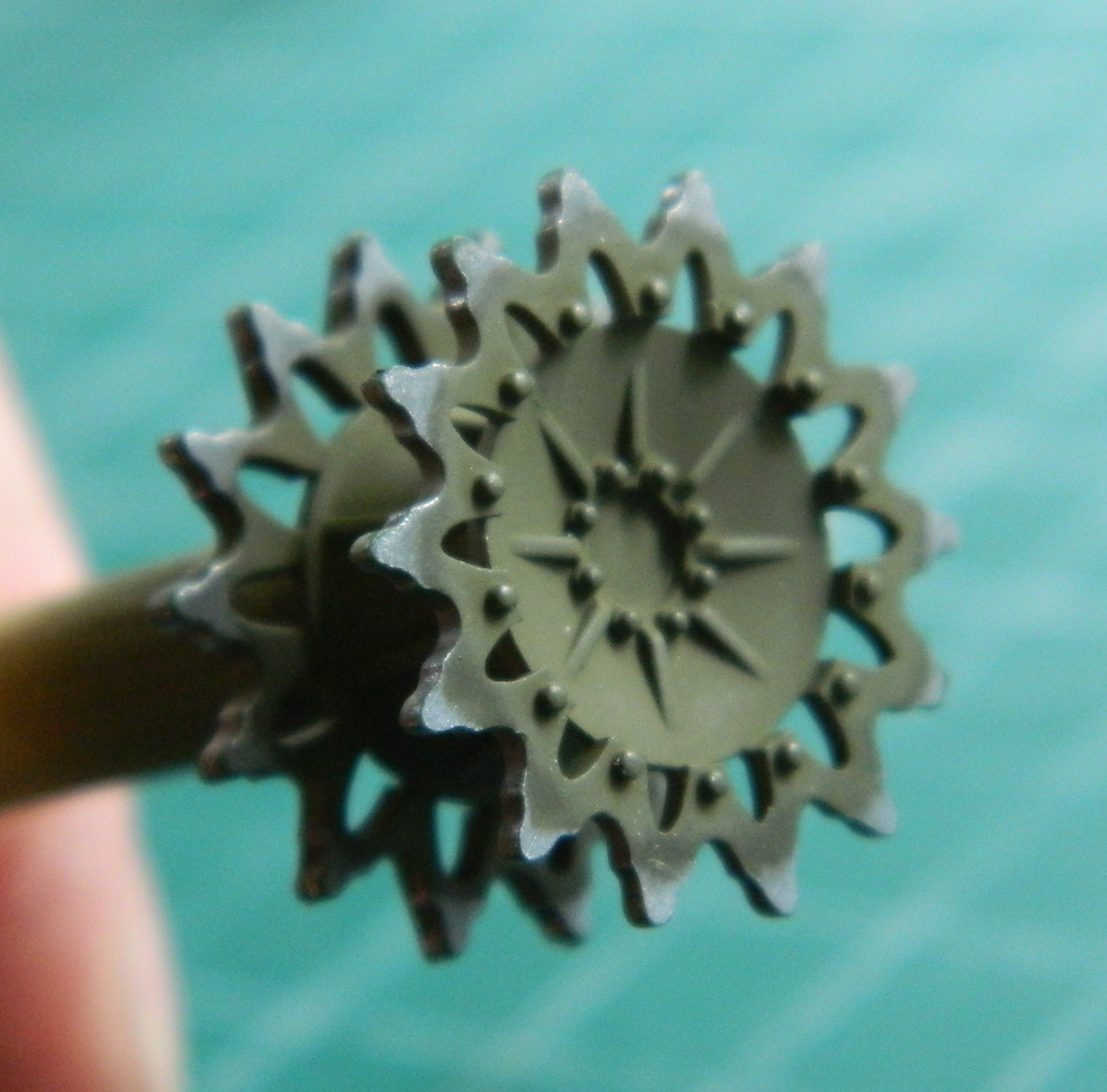
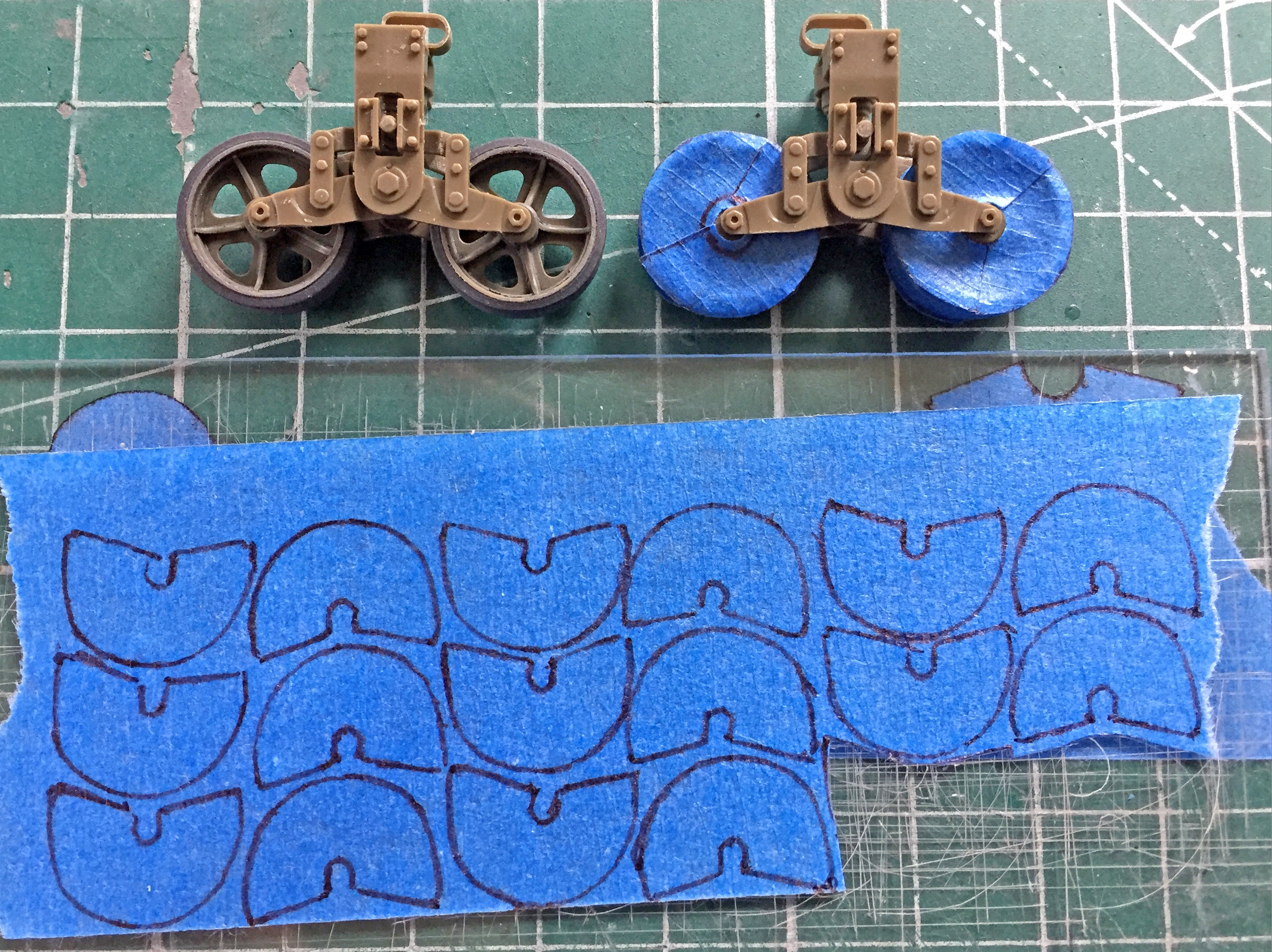
I don’t know why it was so, but I noticed that the M3s used in the invasion of Guadalcanal showed wear on the sides of the road wheels, leaving a shiny surface. So when I started painting the suspension, the first thing I did was to put down a coat of Humbrol’s steel paint. Once it dried, I painted over the steel with Tamiya’s XF-62 Olive Drab. With the OD dry, I used Tamiya’s thinner on a cotton swab to remove the green, starting with the drive sprocket’s teeth:
I masked the road wheels prior to shooting the suspension with the OD:
Once the suspension parts were painted, I laid down clear gloss and treated them to a wash. After an overnight wait, clear flat finished them:
With the suspension done, I finished populating the inside of the crew compartment, and used dry brushing and pastels to wear, stain, and chip things:

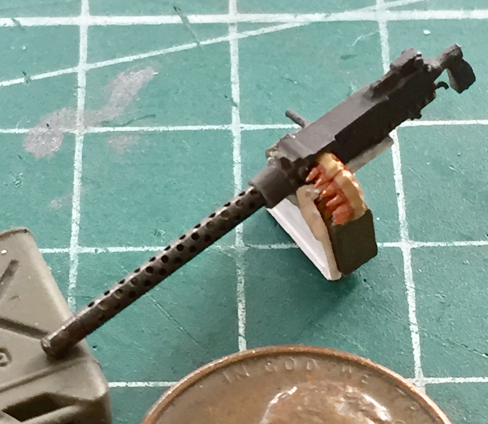
Dealing with the bow machine gun proved fiddly. That length of belted .30 caliber (7.62mm) ammo was a PAIN to heat, bend, snap, cut another section, heat, bend snap, and cut another section:
And I’ve decided that I don’t like Tamiya’s “gunmetal” paint. The paint itself is fine, I just think the color is off. I used a mix of five parts of Tamiya’s X-18 Semi-gloss Black and four parts of Tamiya’s XF-2 flat white to achieve something I think looks more realistic:

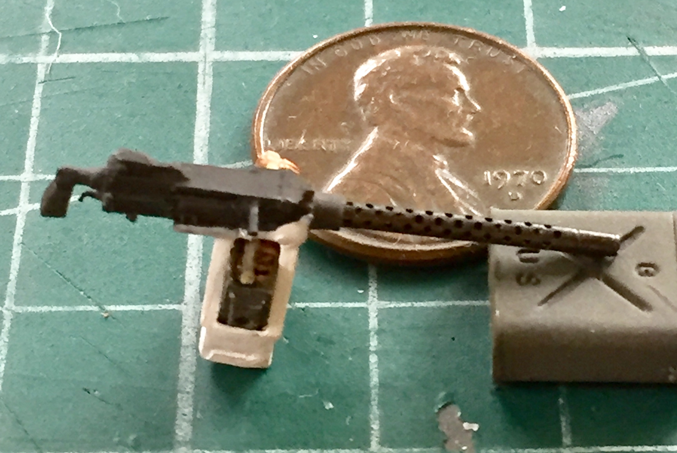
Painting and gluing it together was easy by comparison:

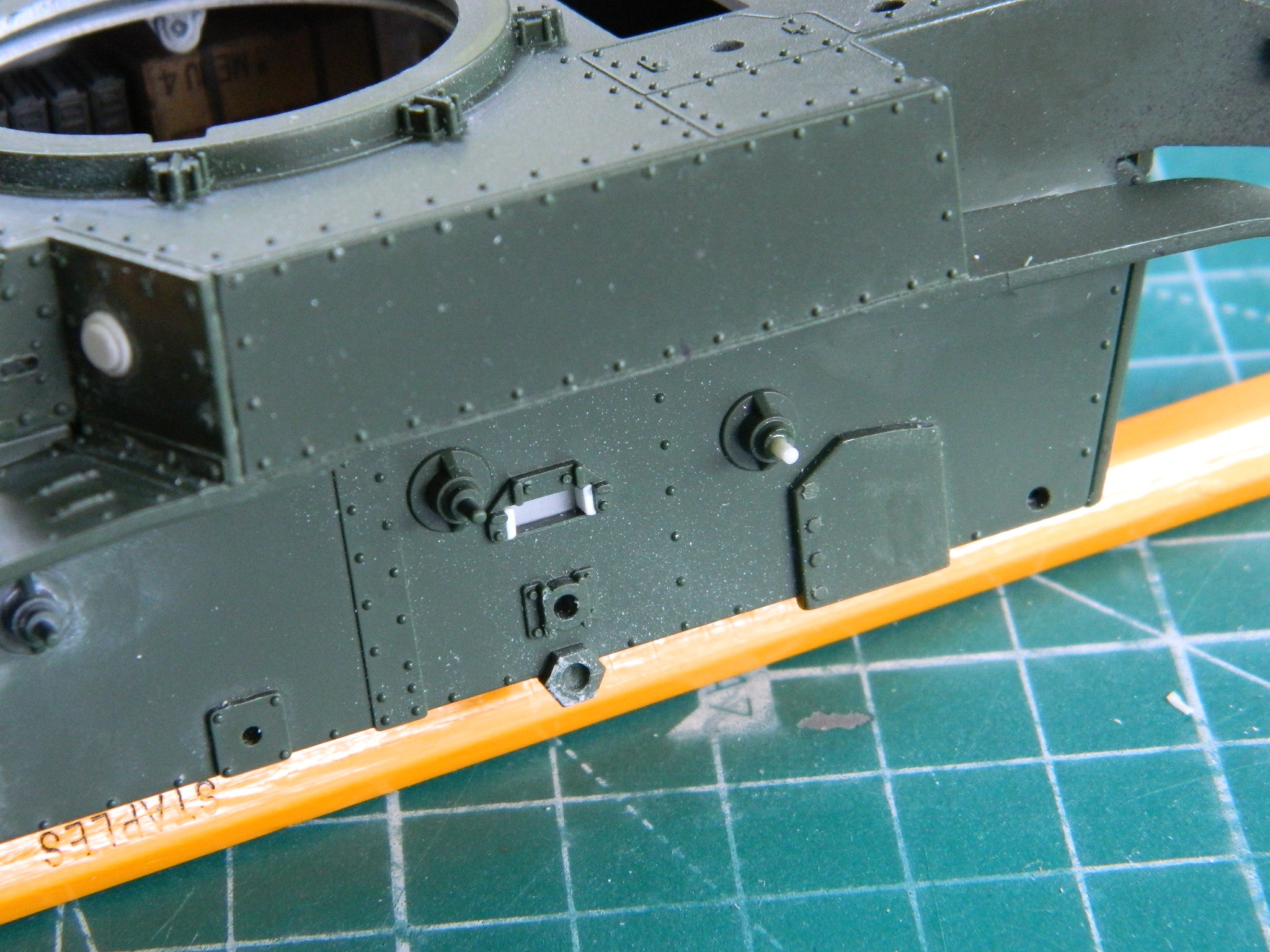
During handling and clamping things to the bottom hull, I managed to snap off four of the six little plastic pins that the return rollers attach to. As luck (good, this time) would have it, Evergreen’s styrene rod 3/64″ (.047) (1.19mm) was a perfect replacement. I drilled out where the rod went, glued them in place, then trimmed them. The white plastic in the rectangular holes was put in there to adapt the AFV suspension bogies to fit the Academy hull snugly:

Something else that had to be modified to fit was one of the commander’s hatch halves. These will be modeled open, but even so, to my eye something was off. I added a strip of .040″ (1.016mm) styrene to the offending hatch half:
I added the bow gunner’s .30 caliber (7.62mm) to the front hull. And as it turns out, all the fiddling I did to get the belted ammo fitted and painted was largely a waste of time. It can’t be seen with the turret in place. And more fit problems showed up. Where the front instrument panel would fit isn’t close to where it’s supposed to go and the spare .30 caliber (7.62mm) ammo cans simply would not allow the gun (and therefore the whole damned front sodding HULL) to fit. It was easier to take the spare ammo cans out:
Okay. So that you understand why what happened next did happen, a bit of personal history…
I had spinal fusion surgery (L4-L5 and L5-S1, if that matters to you). It went about 50% correctly, meaning that it went about 50% incorrectly. In short, a nerve in my back is impinged, probably by scar tissue. Why this matters is because like a lousy wiring job, sometimes it shorts out. Sometimes that’s just a WHAM, a flash of white light, and it’s over, and sometimes I can be in bed for days. That said…
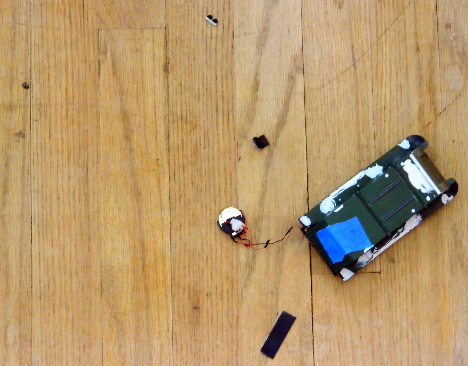
After gluing the upper hull to the lower and taking the above photo, I laid in the white acrylic putty to fill gaps in the sponson bottoms. As I was prepping to sand the putty, I noticed that previous sanding sessions had gotten putty dust all over the bench. Before adding more dust to the dust I already had, I figured I’d clean up a bit. I took the cordless vacuum, which weighs 2 lbs. and 15.5 oz. (1.345kg) and started vacuuming up the
WHAM
When the white light cleared, the cordless vacuum was on the cutting pad where the tank had been. The tank? I found it on the floor about five feet (1.524m) from where last I’d seen it:
Yes. There are pieces lying on the floor next to it…pieces that, when last seen, I thought were attached. Then I picked the parts up and put them on the (now GODDAMNED CLEAN) bench.
My cleverly hinged rear plate now sported a broken hinge:
The interior had been rearranged:

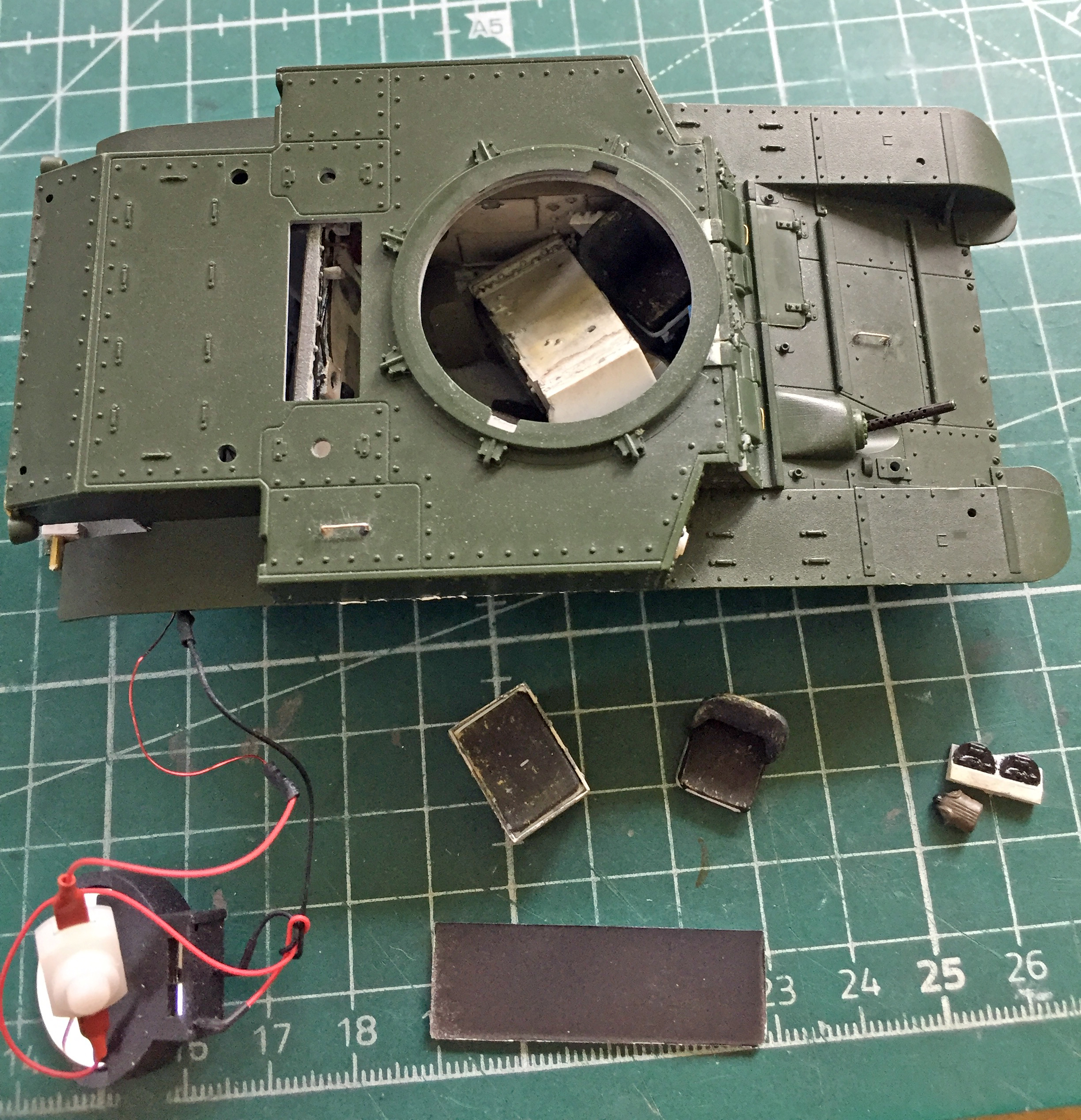

And these were the parts completely dislodged:
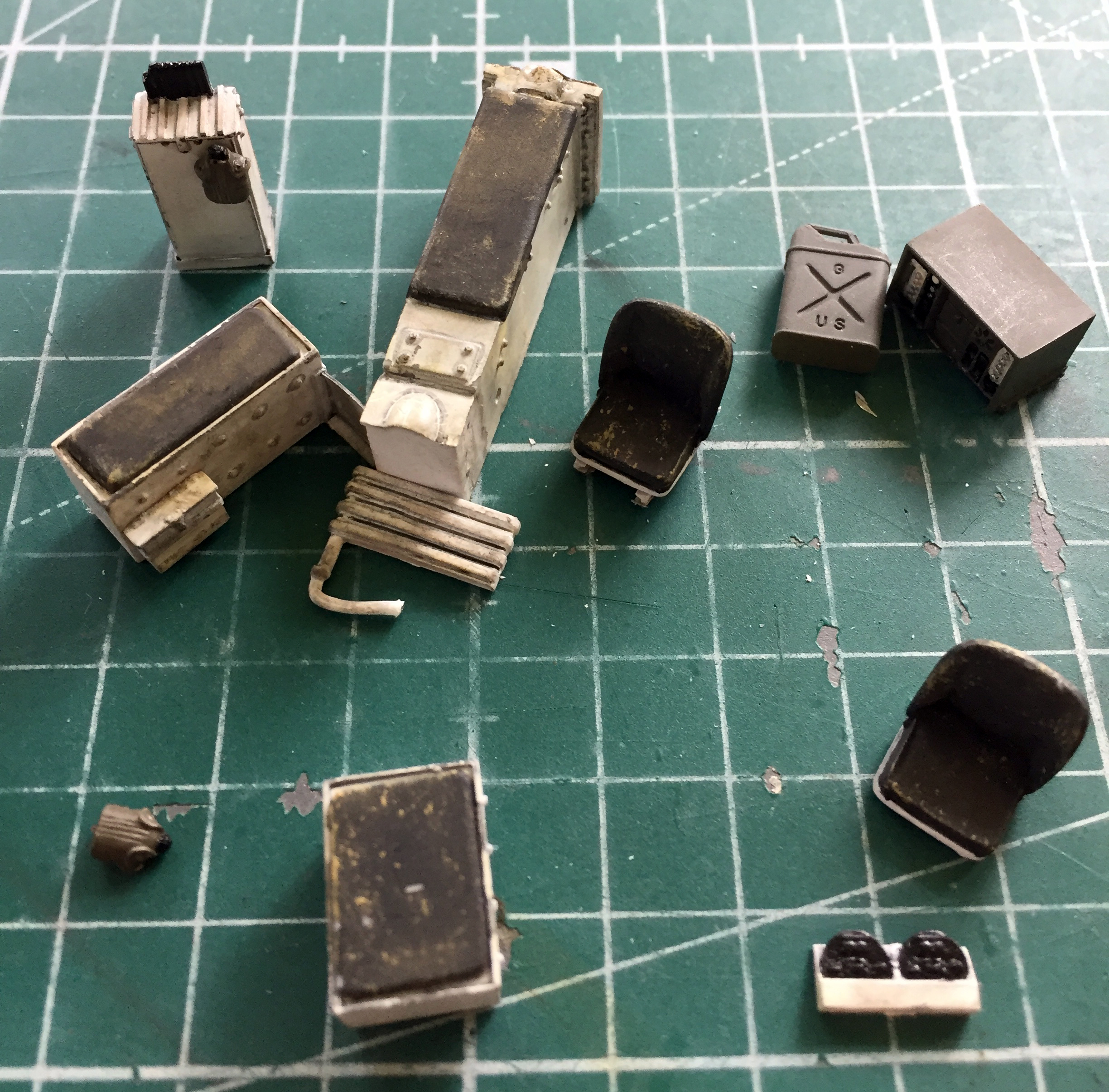
I dread having to take something apart after I’ve glued it together; I am NOT stingy with glue. For all these parts to have come loose, I’m surprised there was no damage to the plastic of the hull. Only one sponson had pulled free from where I glued it. However, in order to put back INside all the stuff I found OUTside, I was going to have to complete the job of removing the upper hull from the lower.
And I did. I felt like I was trying to defuse a bomb while blindfolded during the process, but before I went to bed that day, I’d recovered about 90% of what needed to be fixed:
WHEW.
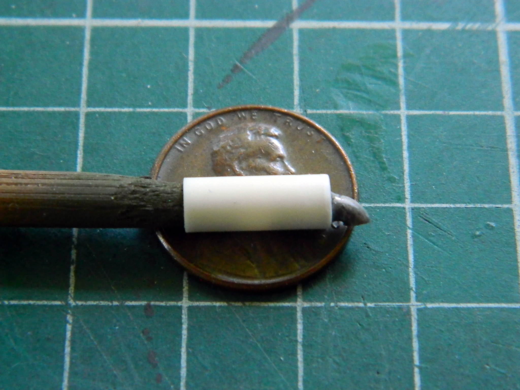
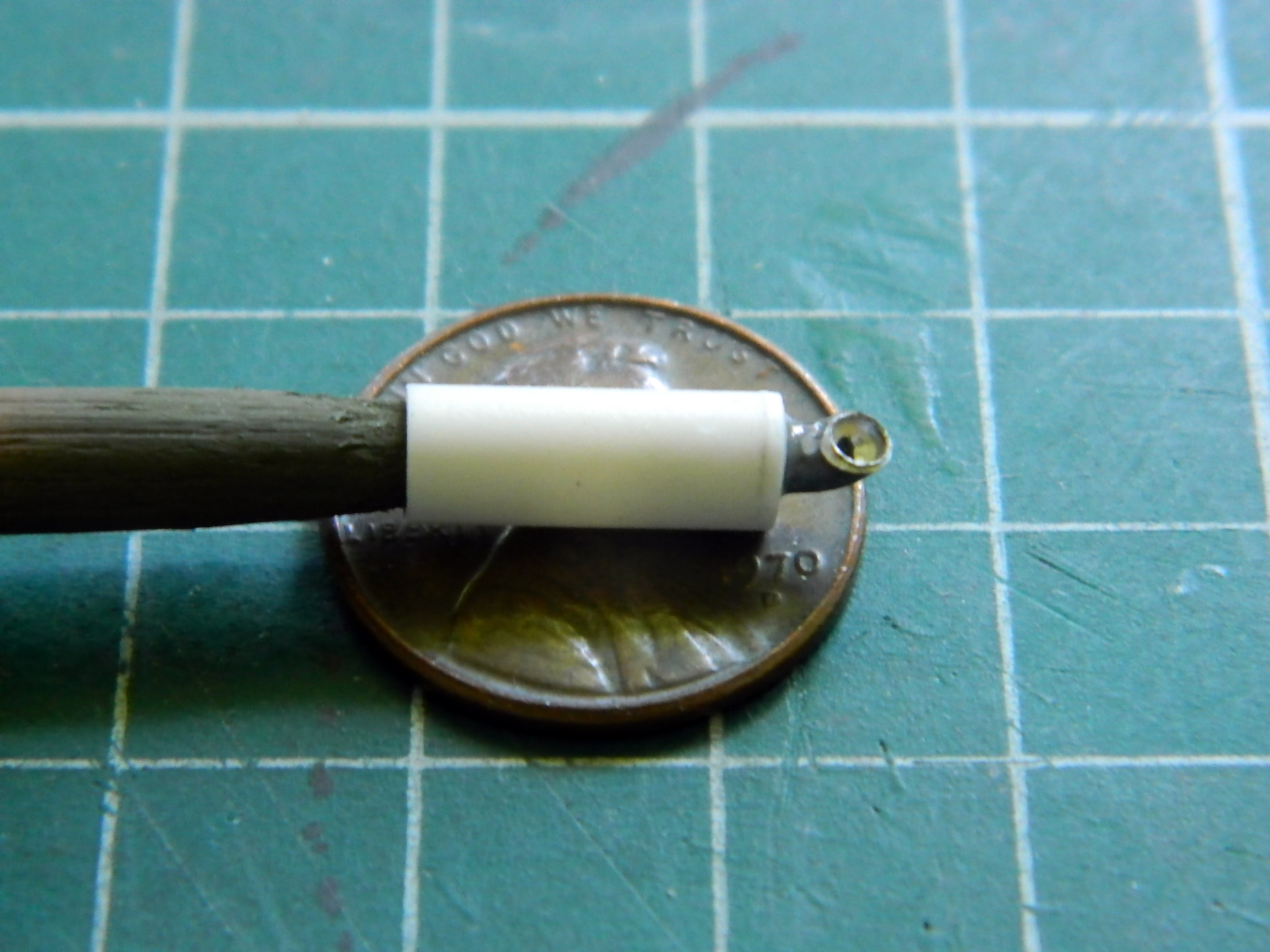
Moving right along, I made the mufflers and exhausts that live under the rear overhang of the upper hull. I used 1/4″ (6.35mm) styrene tube, capped it with .015″ (.381mm) scrap, and .093 (2.36mm) solder with drilled out ends:
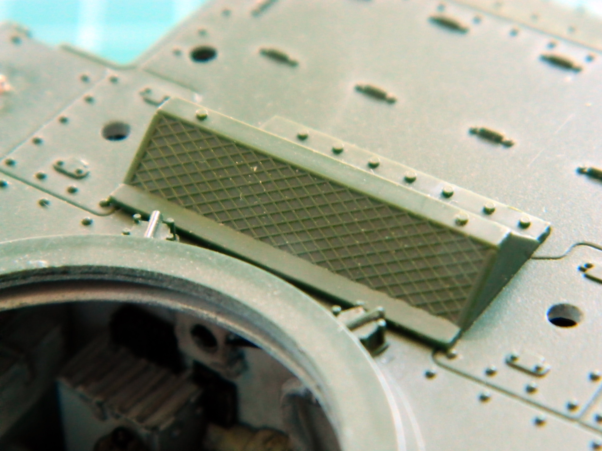
After painting them rusty brown, they were glued in place and PE mesh cut and glued in place and painted with Tamiya’s XF-62 Olive Drab:
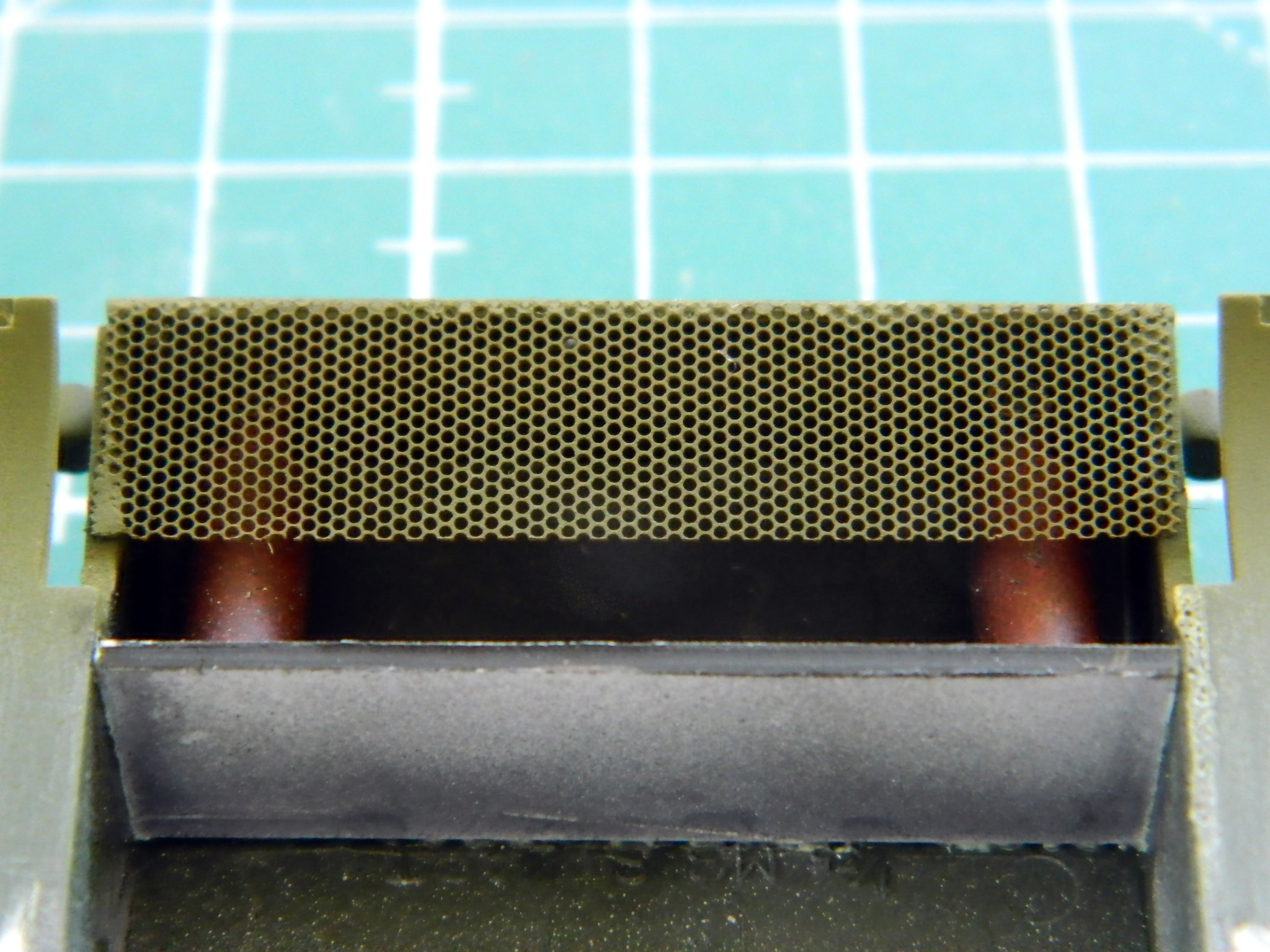
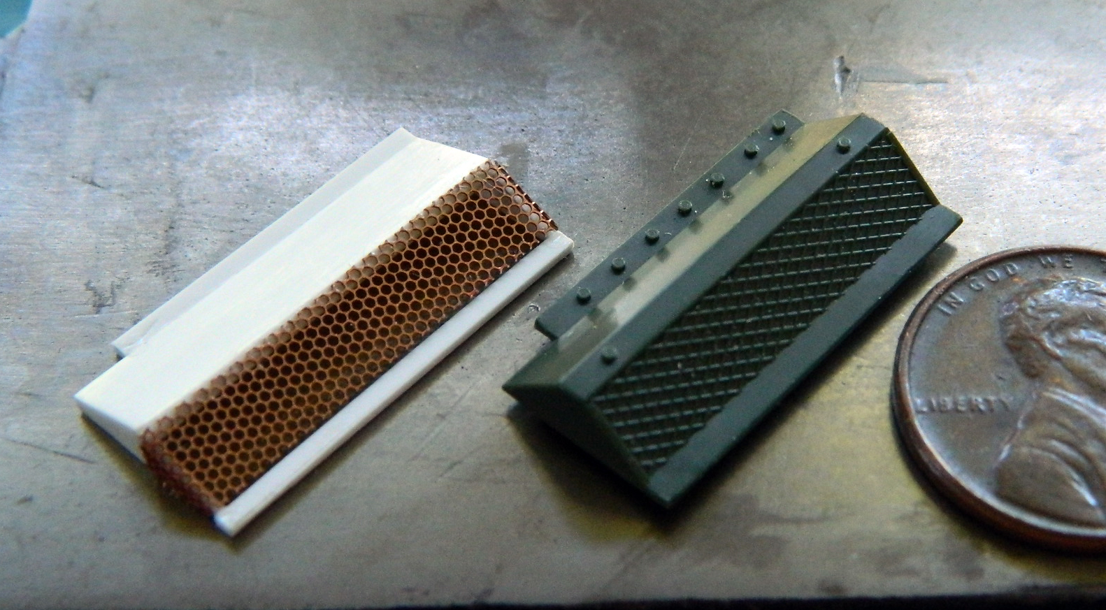
In checking references, the air intake over the engine was too tall, so I scratch built a correctly sized one:
The end pieces were cut from .020″ (.508mm) scrap; the kit part was traced onto the plastic, which gave me the reference I needed to draw the replacements:
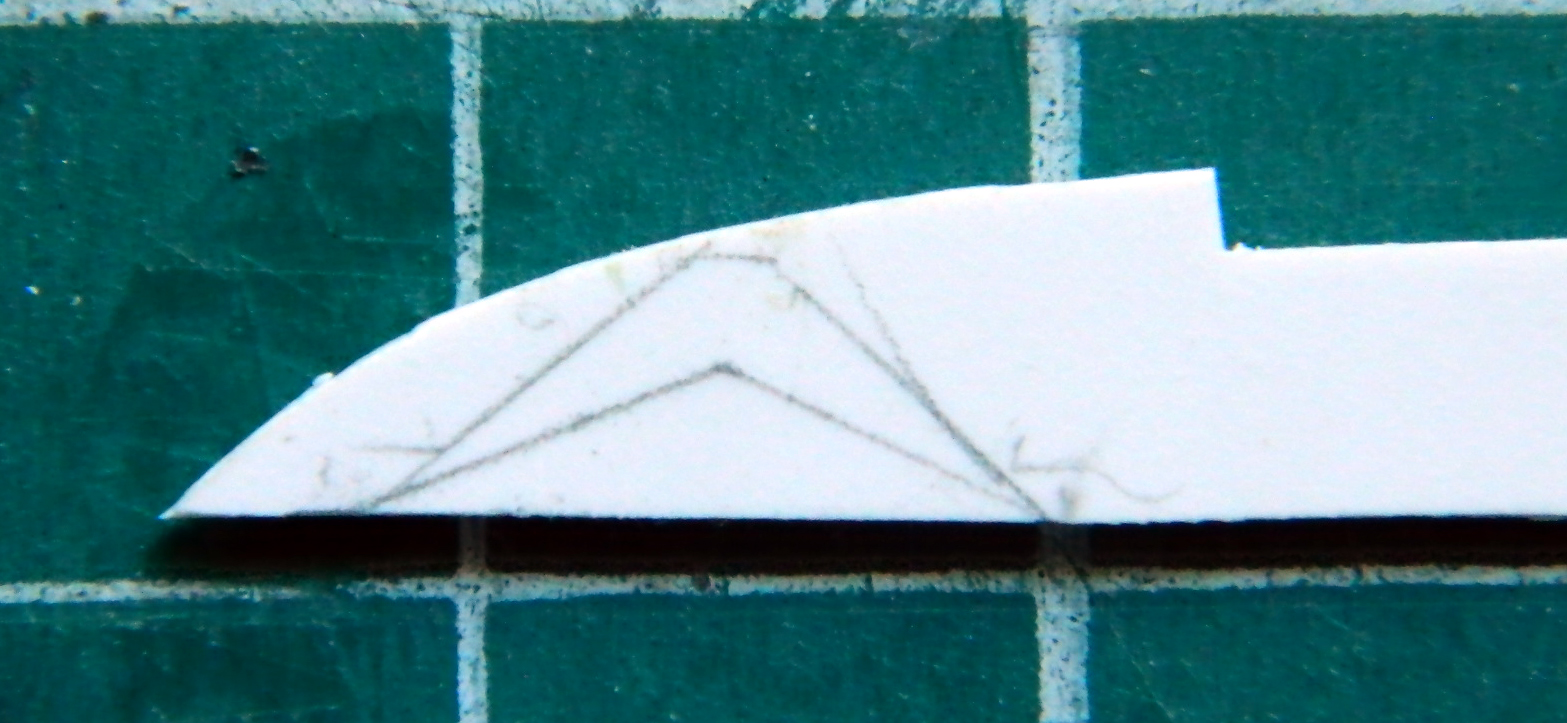
Adding more PE mesh, I ended up with something more accurately sized:


Did I mention, “whew”?

Lower backs is buggers. Some intelligent design – not!
LikeLike
Too true!
LikeLike