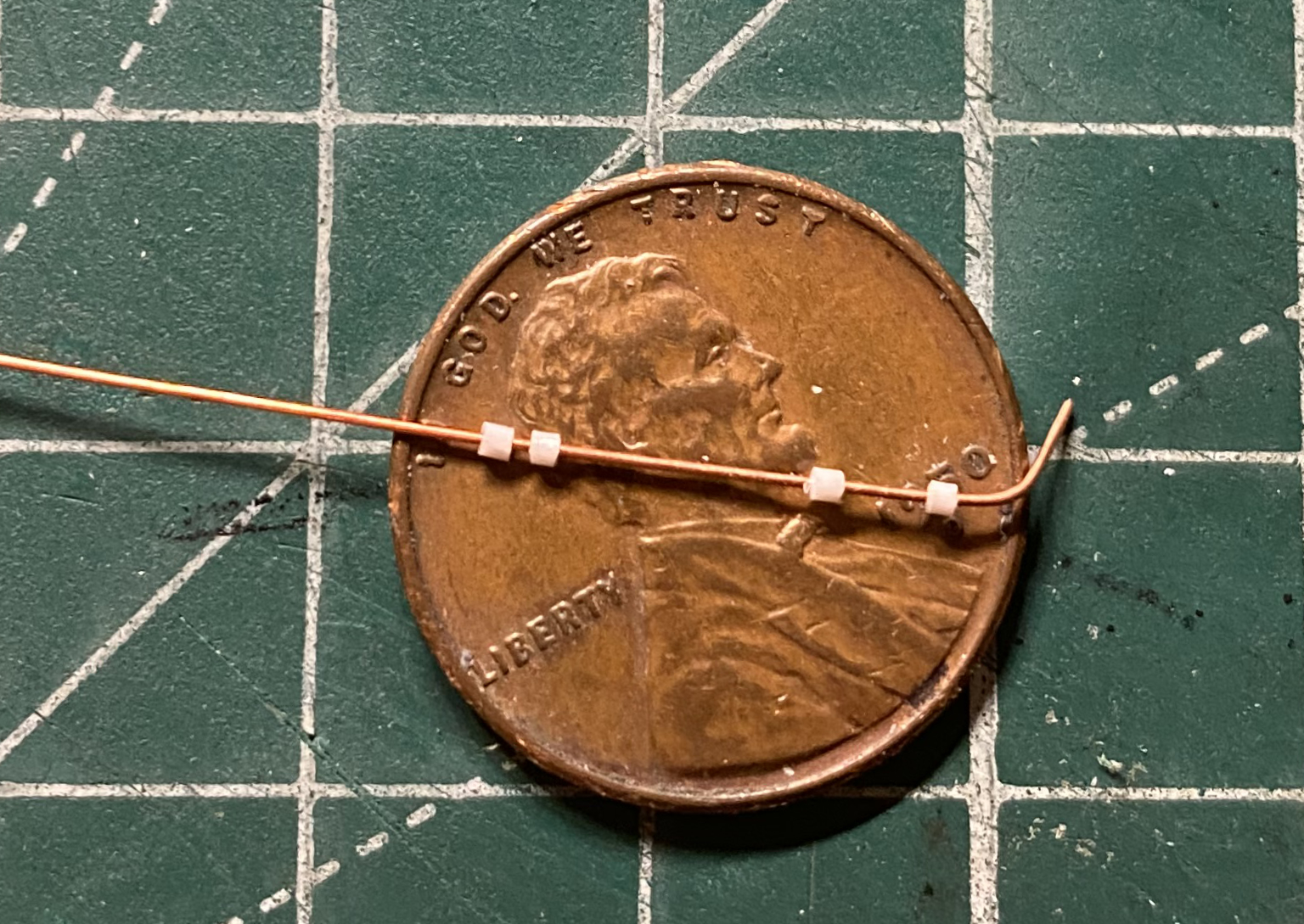
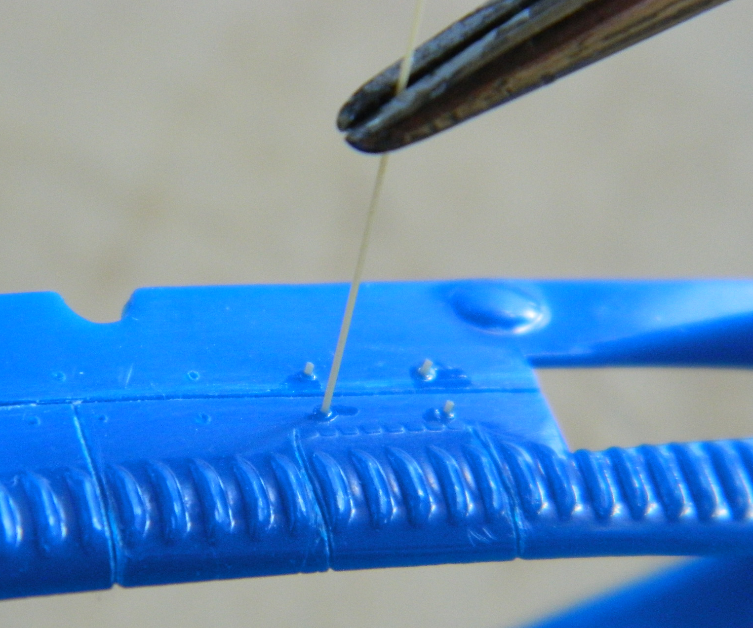
This month saw me dealing with two of my favorite chores (sarcasm)…scribing panel lines and lots of really small details. There aren’t many panel lines but the few that are there are surrounded by about 44 repetitive details that got sanded away so that I could start scribing. And the first thing I did on the first panel line I tried to scribe was to bobble the tool, which sends the line where I don’t want it to go, so then I get to stretch sprue to fill in the errant line so that I can do the line correctly next time. I used sprue from the kit so that colors match and in so doing give my ancient eyes a break:
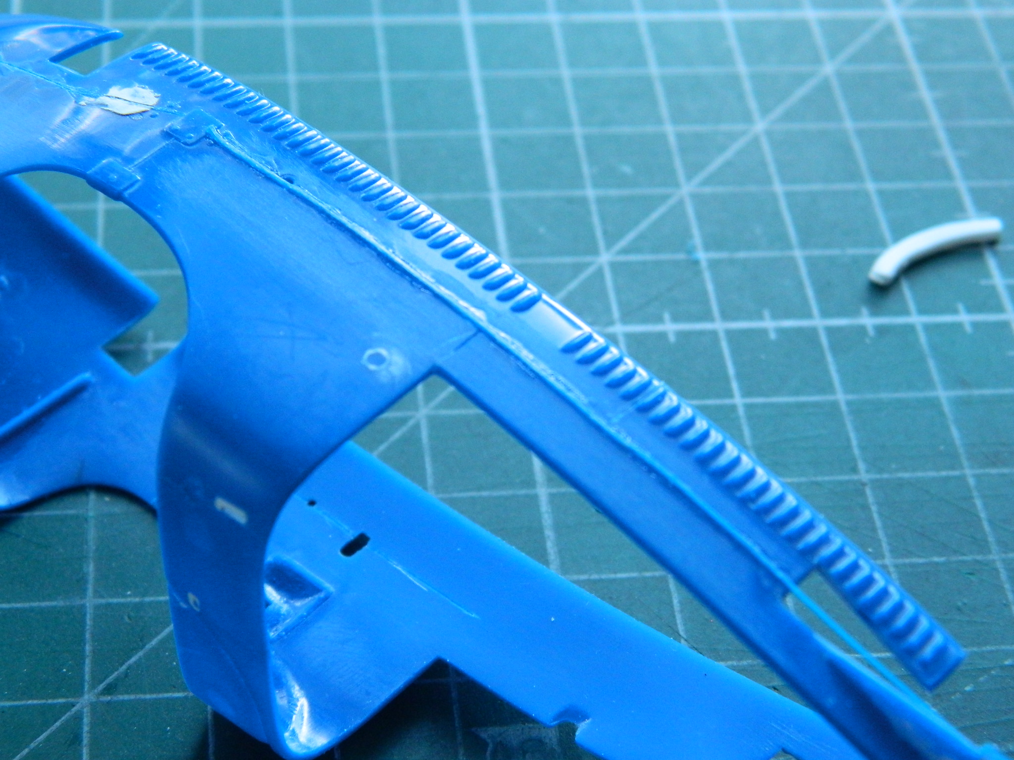
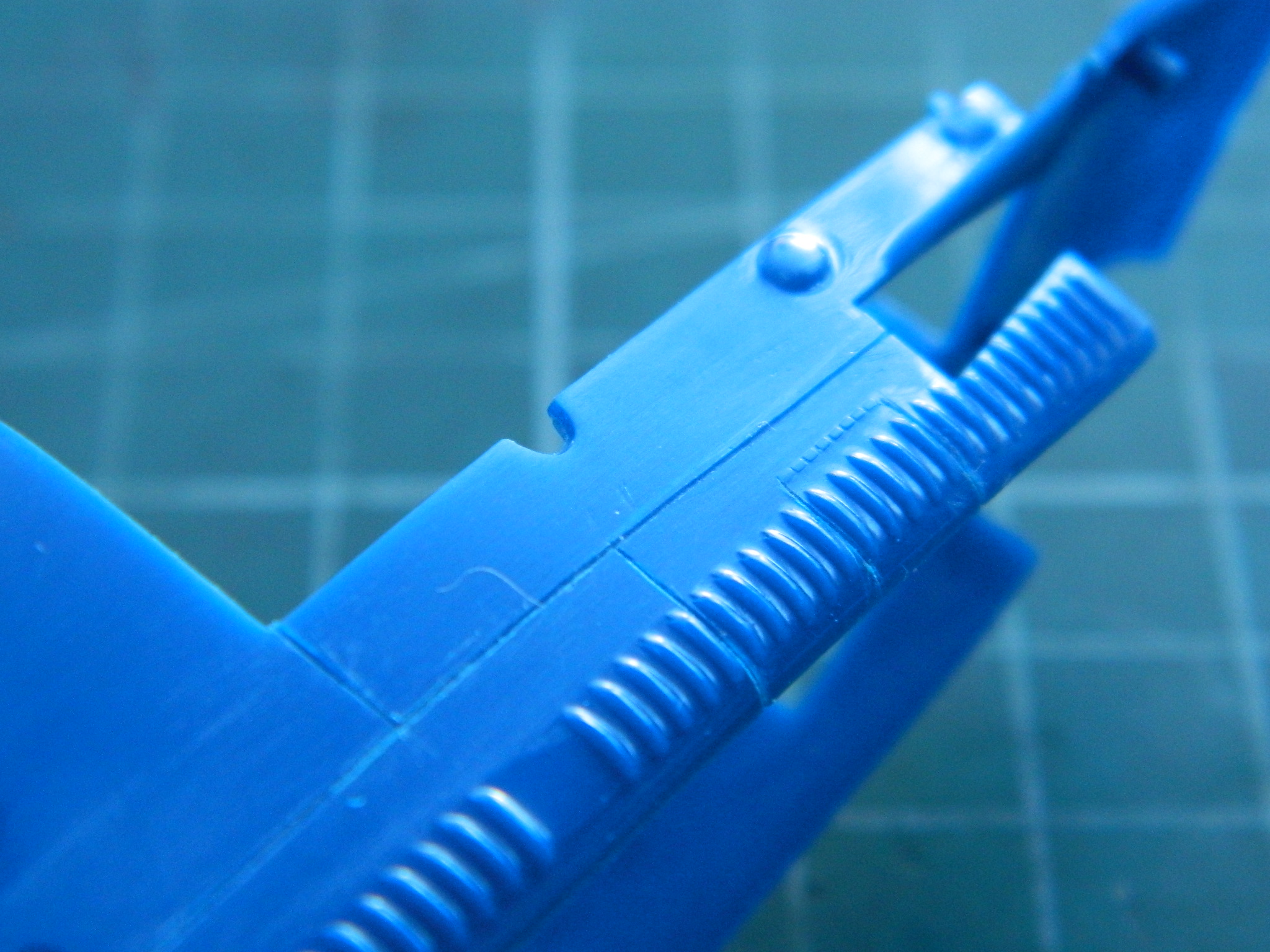
I let the body sit overnight so that the glue had totally evaporated and the inserted run of sprue was of the same consistency as the surrounding plastic (which turned out to be quite brittle) (sort of like I am) before I sanded it down and tried scribing again. The second try went better:
I’m sure this must be a common lament with any miniature builder. I don’t have enough hands. I ran out of patience trying to make two hands do the work of 173 hands during dry-fitting so to cut workload (and frustration) down, I glued the engine/transmission in place:

With that firmly glued in place, I started to add the shaft that the clutch and brake pedals are on and discovered that for them to fit less incorrectly (because as my last post showed, I had to move the shaft rearward), I needed to hog out a channel under the bell-housing to clear the shaft (and since this car had a full body belly pan, that will not be noticed). Once done, the shaft and its pedals were glued to the frame:

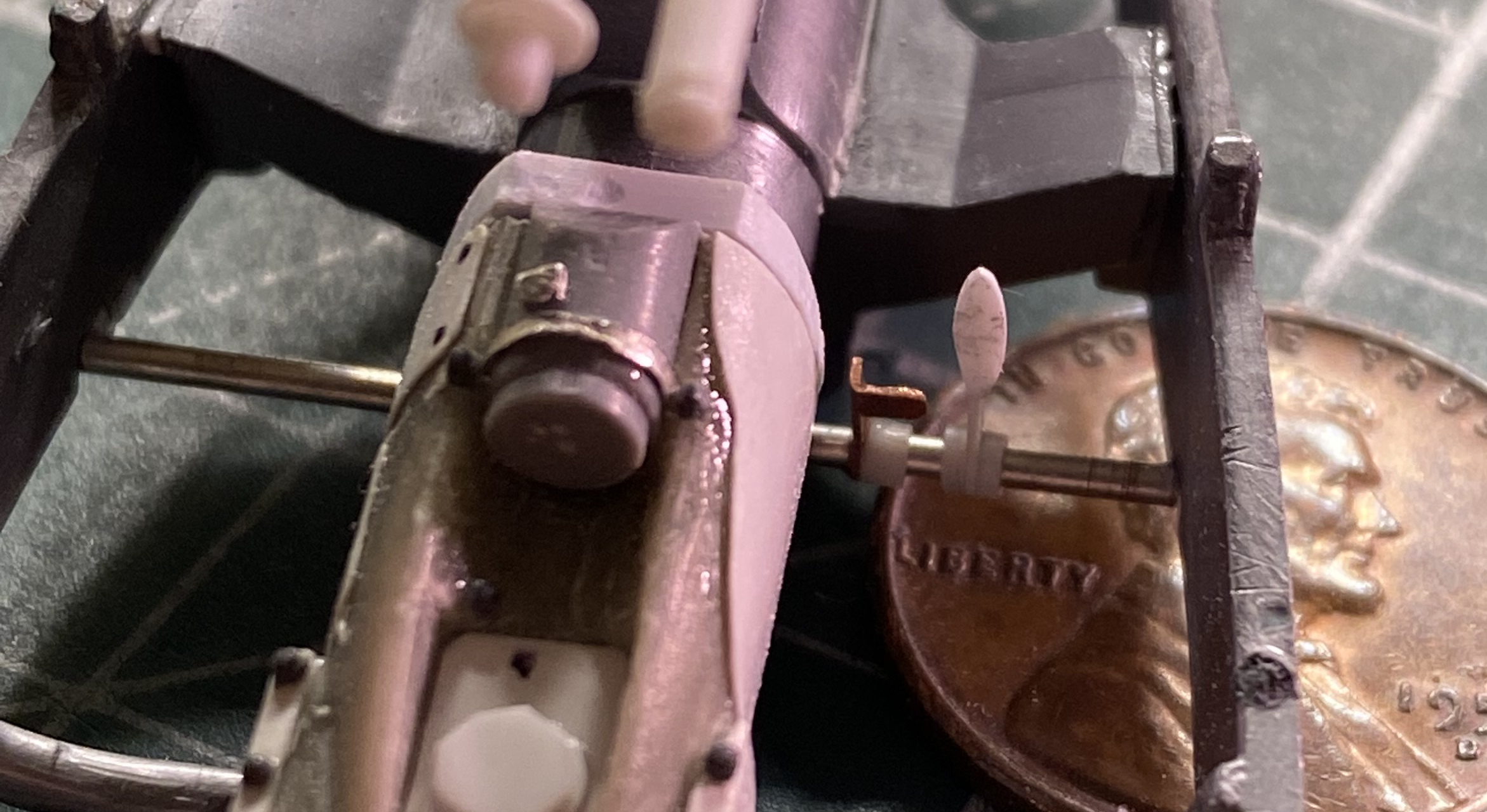
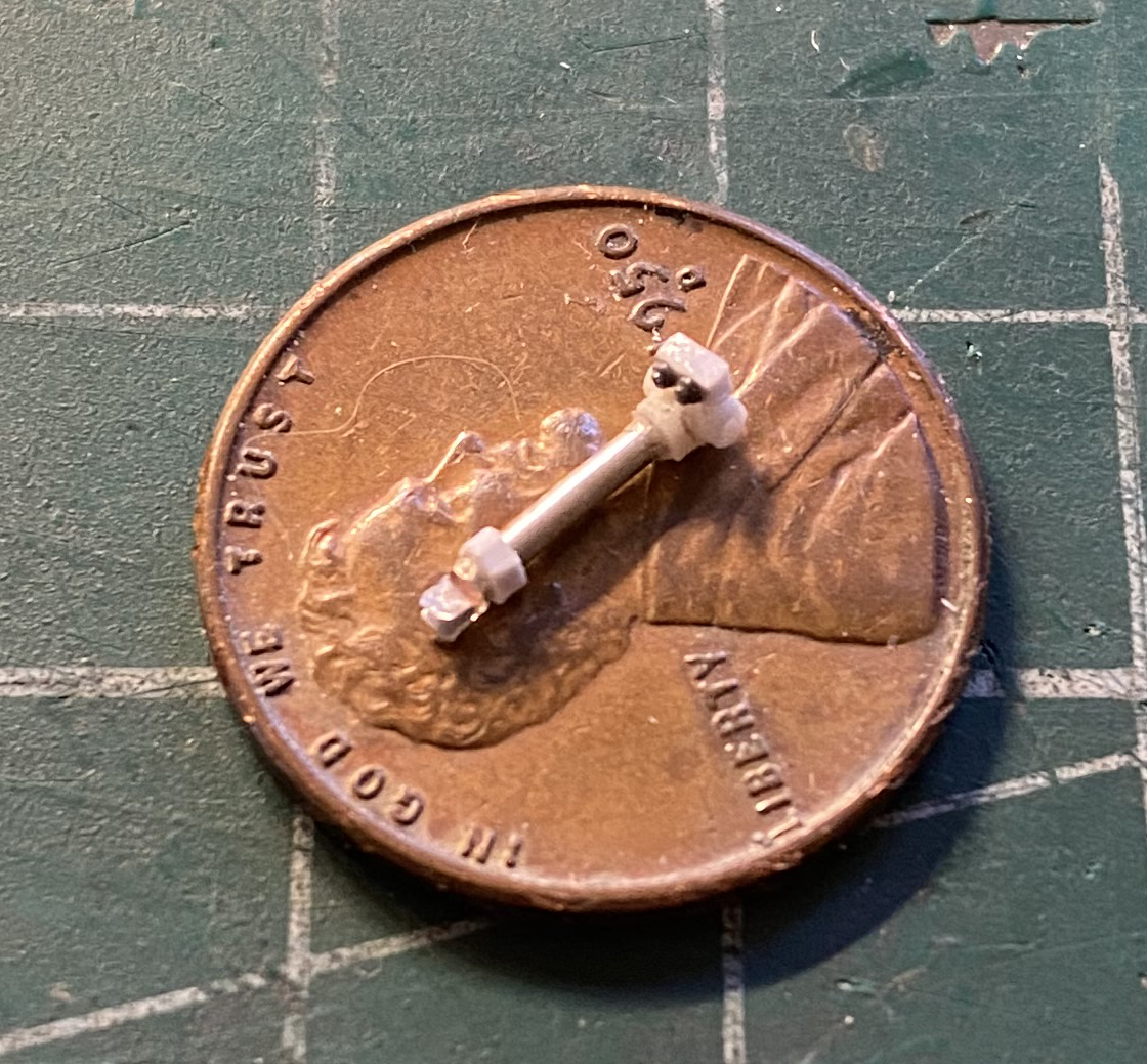
Since I was getting the pedals situated, I decided it was time to build the throttle pedal. I don’t know if it was because automobiles were less than 35 years old when this car was built but the throttle pedal is less of a “pedal” and more of a roller on the end of a shaft (must have made heel-and-toeing a genuine challenge). But regardless of its configuration, I needed one so I built it. The real challenge was cross-drilling a very small styrene rod so that the roller could be glued to the throttle linkage. I persevered, trimmed the rod, then drilled a hole in the foot-box and slid the linkage into place and glued it:


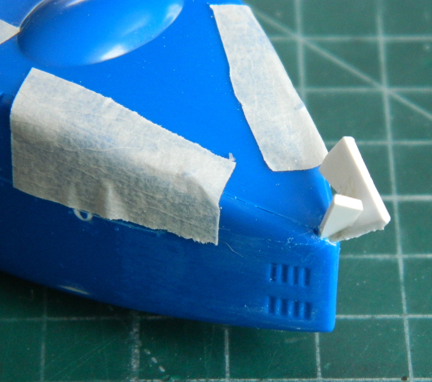
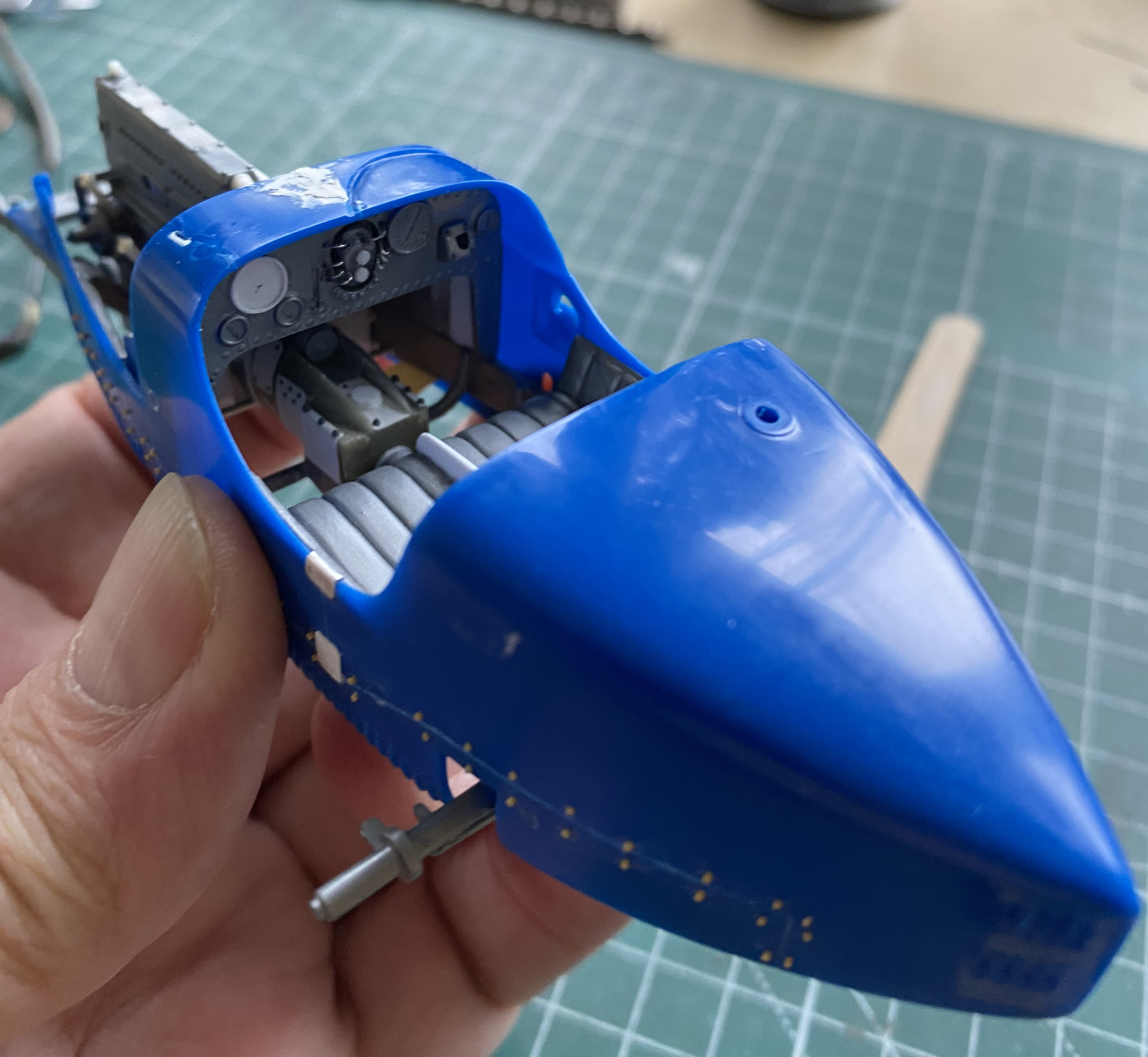
In the process of dry-fitting the belly pan, I noticed the rotten fit here:

I don’t know why that rubbed my rhubarb the wrong way…but it did. So as a calming measure for my delicate sensibilities, I stuffed some scrap styrene into the hole and glued it to the boattail (obviously, later on I’ll trim those chunks down and finish closing that hole, but for the present my tender sensibilities are assuaged):

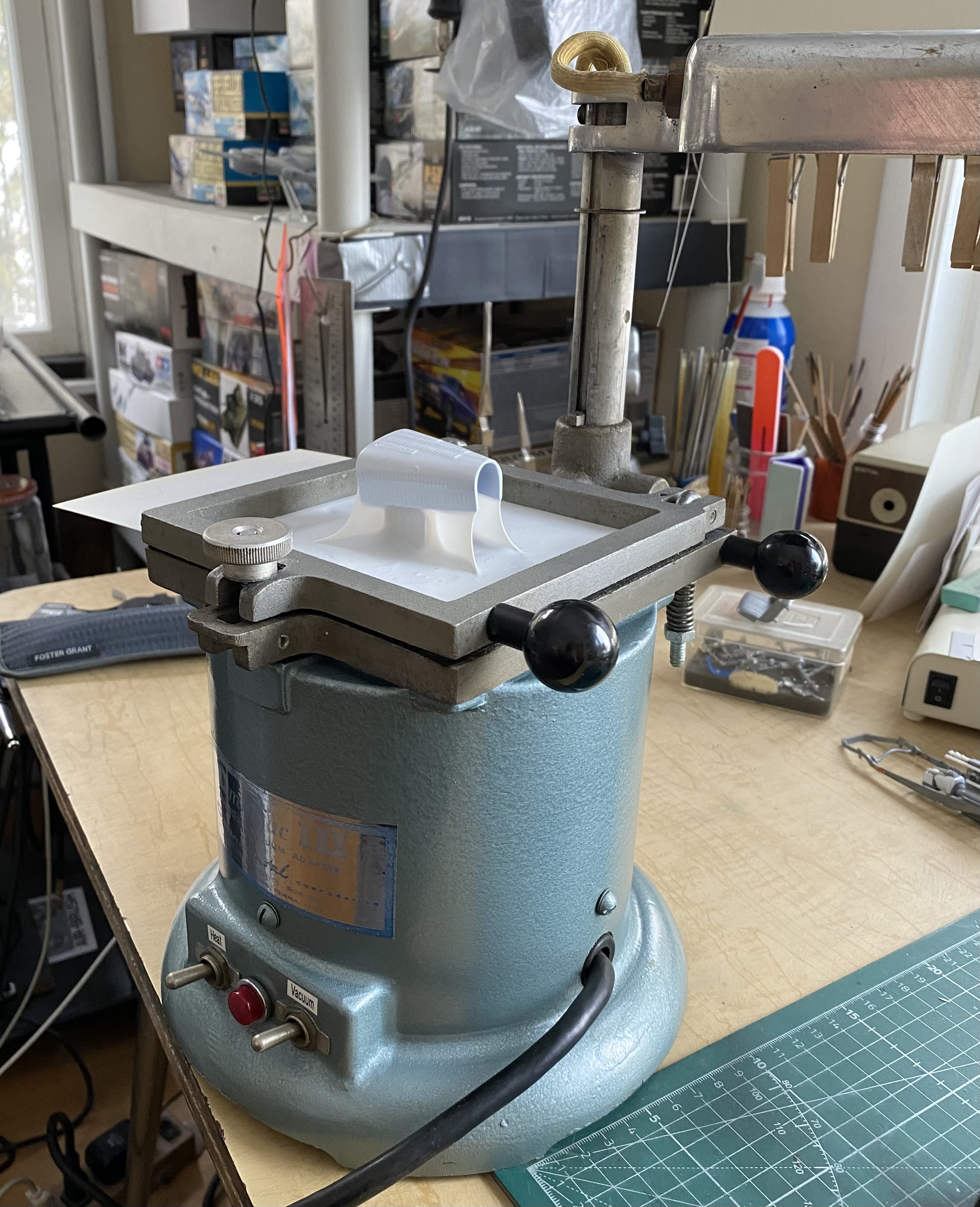
Once upon a long time ago, Finescale Modeler magazine ran an article about how to make ones’ own vacuum molder. For about 25 years it worked well enough. When I was given the Buffalo Model #15 electric grinder, I was also given a dental vacuum molder. That bugger works very well! It has a heating element over where the frame comes up underneath the element that worked as intended. Then when I turned on the vacuum, dropped the frame and the heated plastic over the form, it pulled down quickly and quite tightly. My initial use of it was to pull some .015″ (.381mm) styrene over the kit engine cover so that I could trim most of it away and have the inner framework I wanted, which was then trimmed and fitted:


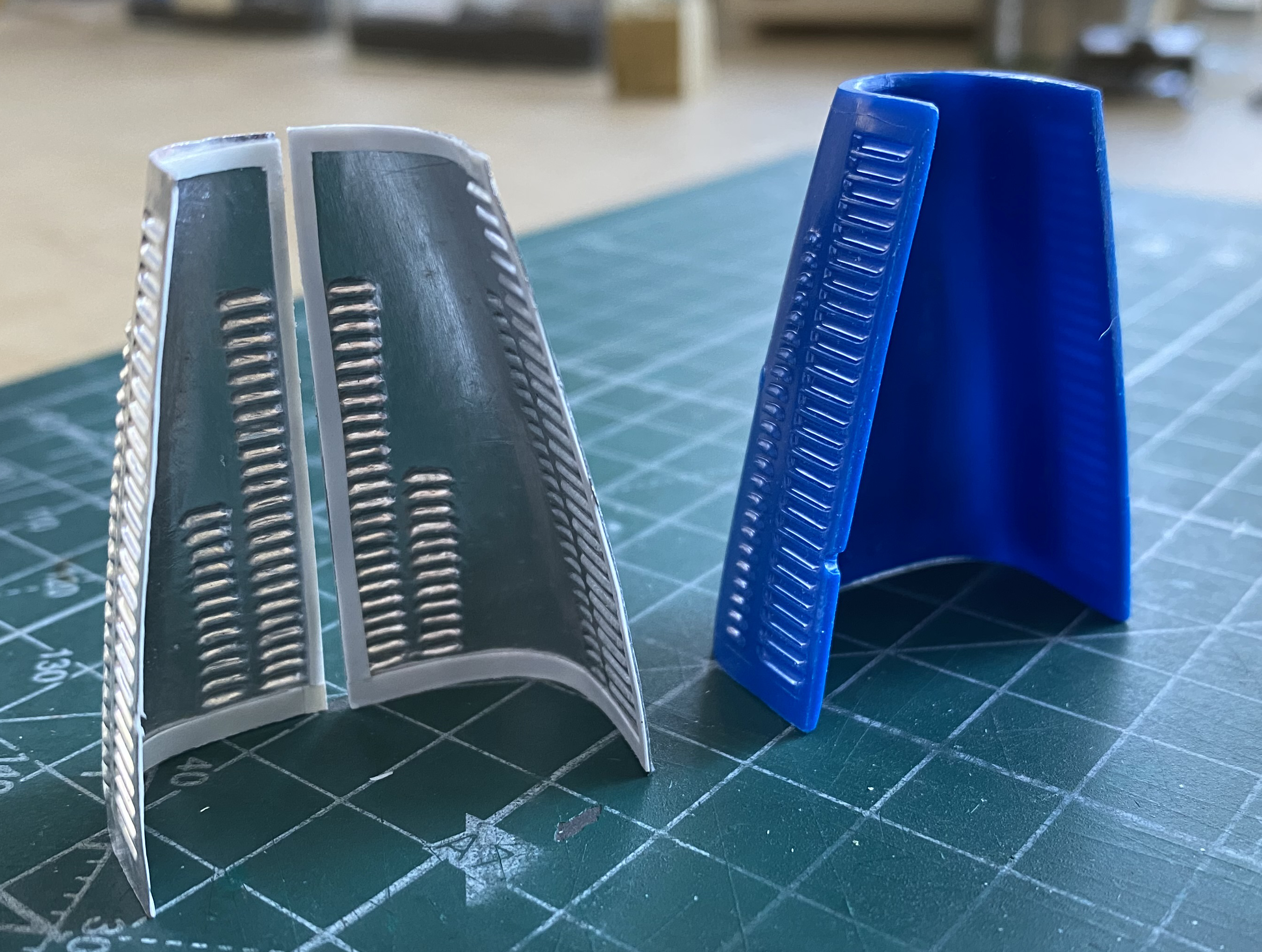
I’m not thrilled with how one side (on the left in the lower photo) came out so it looks like I’ll be redoing that side, starting with redoing the aluminum first:
At some point soon, I’m going to have to install the lines and valves for the auxiliary oiling system. I started that by drilling out some small styrene rod to make the valve bodies:
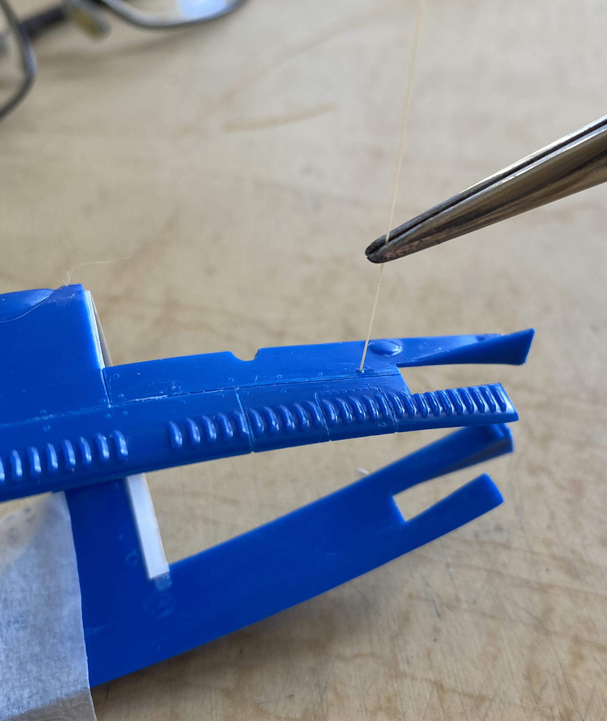
Since putting off an unpleasant task never makes the task go away, I started adding back the body panel fasteners using stretched sprue. I taped the embossed paper in place and then marked locations with a needle pushed through the paper and into the plastic. And yeah…this will take some time:
More than just “some” time:
A lot of time:

Having plenty to do around that tedious task, I started with the pump for the auxiliary oiling system. The main body of the pump is a cut down paper clip (because nothing says “metal” quite like METAL), as well as small bits of scrap styrene and Grandt Line bolts:
The wheels of the Type 35s were cast aluminum and the brake drums were cast as part of the wheels (aluminum brake drums?!). I’m guessing that they were done that way to aid brake cooling (not to mention every tire change also freshened up the aluminum brake drums by replacing them) and as such, circumferential cooling fins were also cast on. There are three fins but this is a very small area and I’ve already impressed you with how poorly I can scribe lines, so I just scribed two of them…five times (the fifth wheel was for the spare tire I’m not using…I figured I’d use the best four out of five…the kit part is on the left below, the modified part on the right below):

Took some time, but I got one side done…then started on the other side:

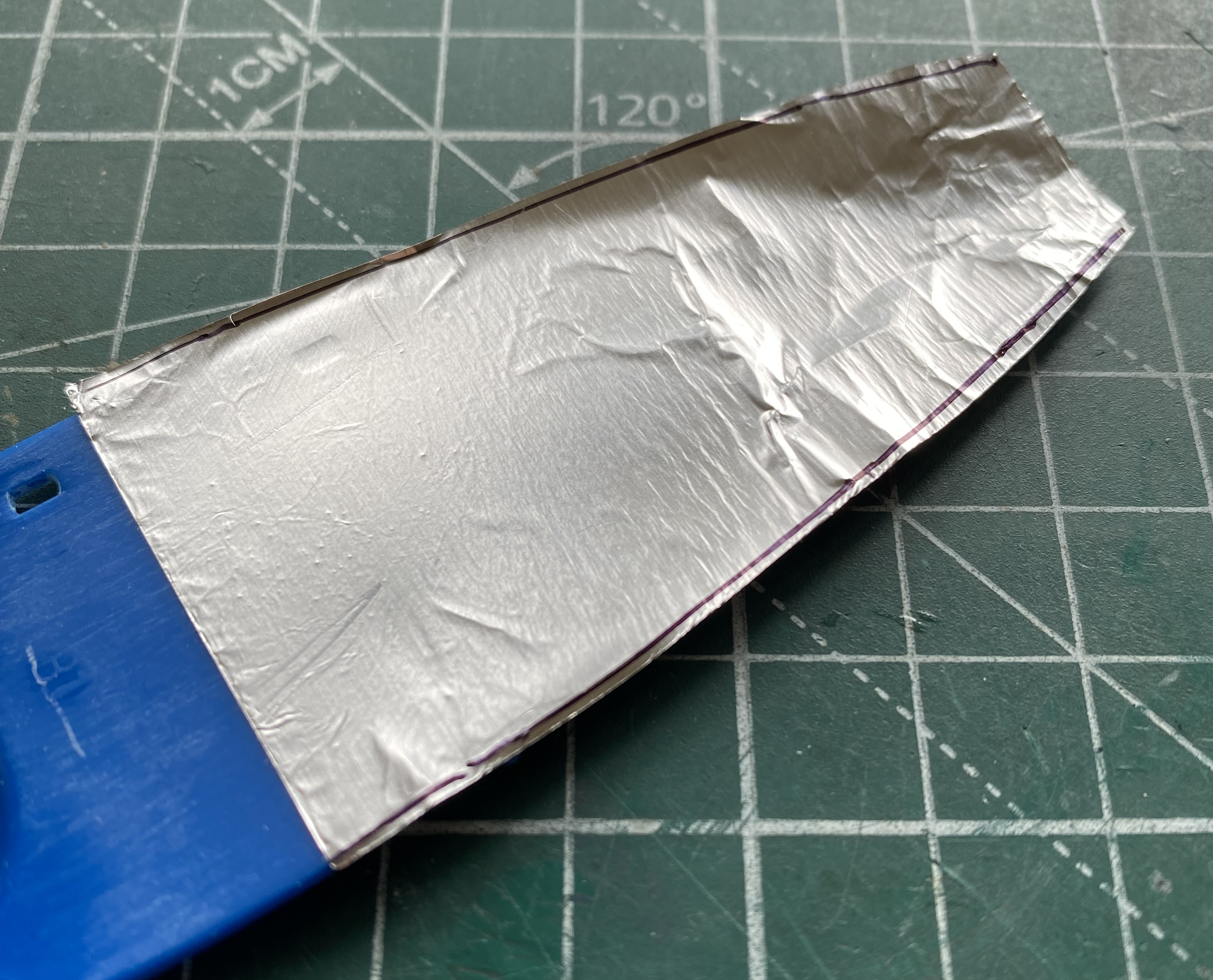
The inside of the body was unpainted aluminum. To simplify painting tasks, I decided to try something that I haven’t used before; Bare Metal Foil. This stuff is THIN! Make sure the surface you want to use this stuff on doesn’t have anything on it that you don’t want to show through the foil (something like a cat hair) (no…don’t ask). Because of the complex nightmare that masking the parts above the floor would be, I used Bare Metal Foil on the floor, eliminating the masking problem completely.
Step one, cut out a piece slightly larger than needed and lay it in place carefully:
Step two, burnish the foil so that it’s flat, working the wrinkles out (I used a cotton swab):
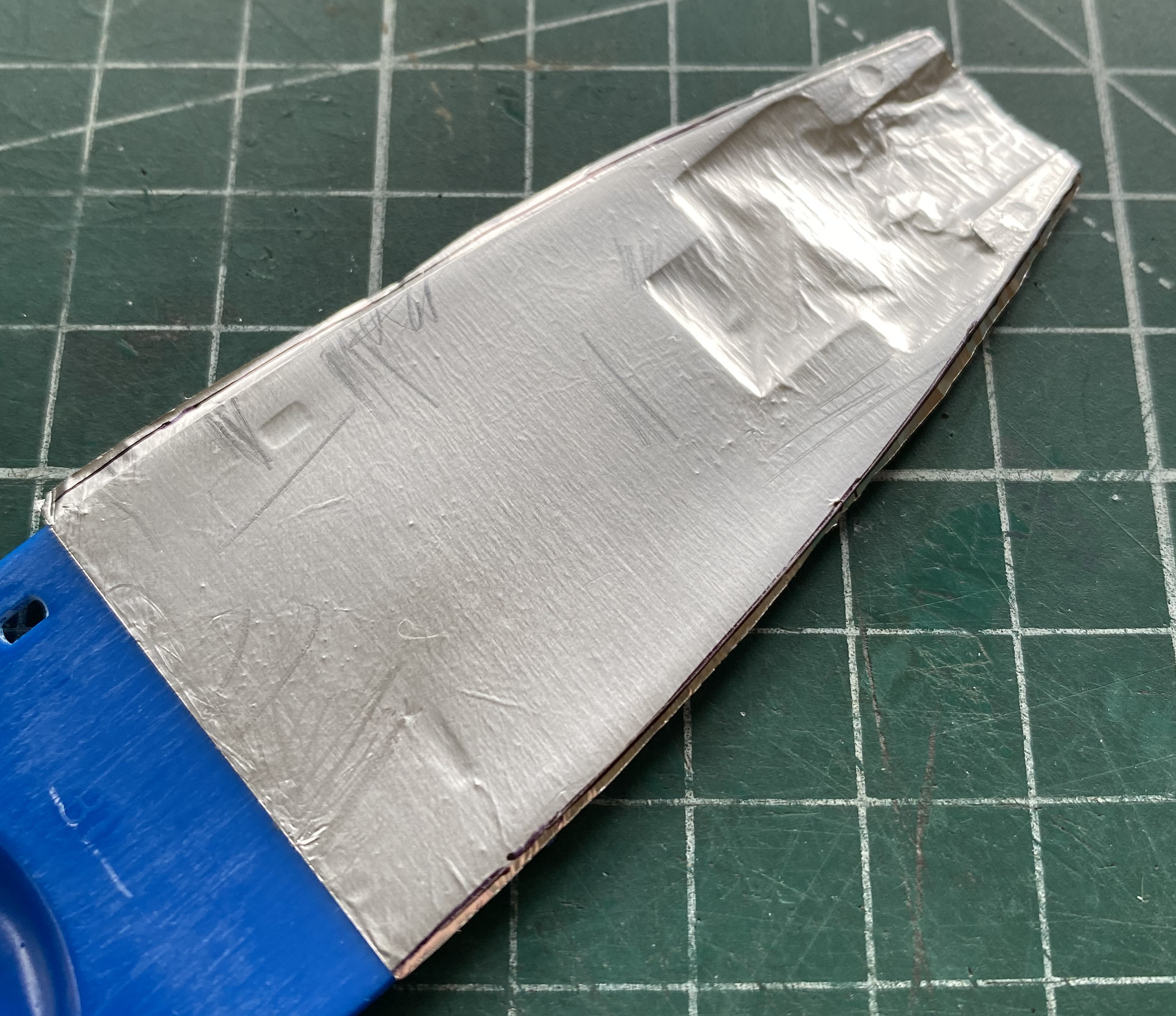
The last step (sorta) is to trim the excess off using a SHARP blade. The least little dullness of your blade of choice results in the foil tearing (again, don’t ask). I used a new razor blade (the second time):

Note the differences in the surface of the foil. These are areas of high(er) wear. I used 2000 grit sand paper and, believe it or not, a paper towel.
I dry-fit the upper body over the frame (after gluing the rear axle in place) to ascertain where the wear areas are and which ones would see the most wear. I also wanted to see how much Bare Metal Foil I would need to line the body (not much) and if the line I scribed inside the cockpit would show (they do not):
Later in the build, each of those panel fasteners I put back on get safety wired. Oh the fun that will be.
