With the crew compartment done, I moved attention and efforts up to the turret. I started putting the main gun, gunner sight, and coaxial .30 caliber (7.62mm) in place (the chipped paint on the gun barrel was from fitting the mantlet):
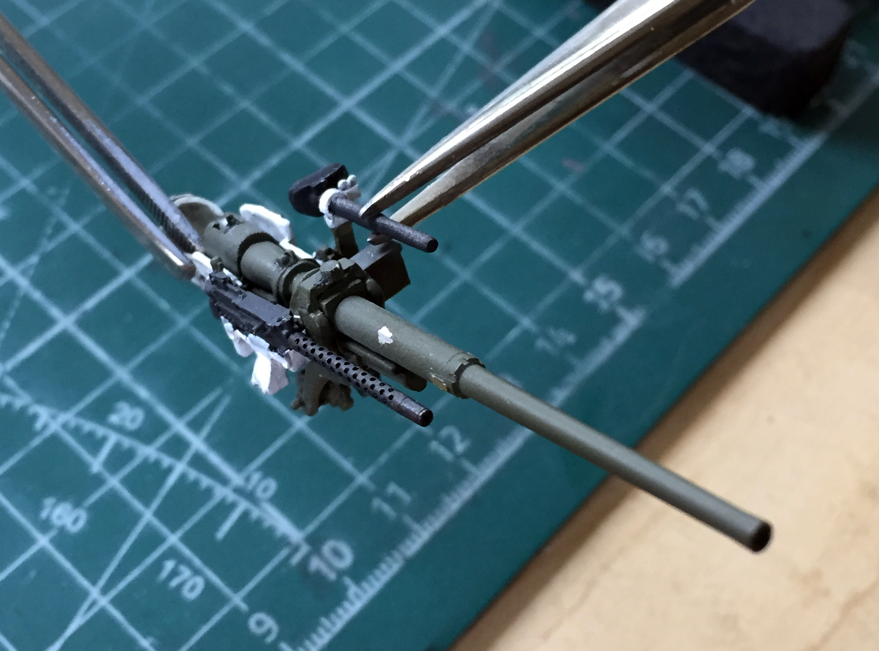
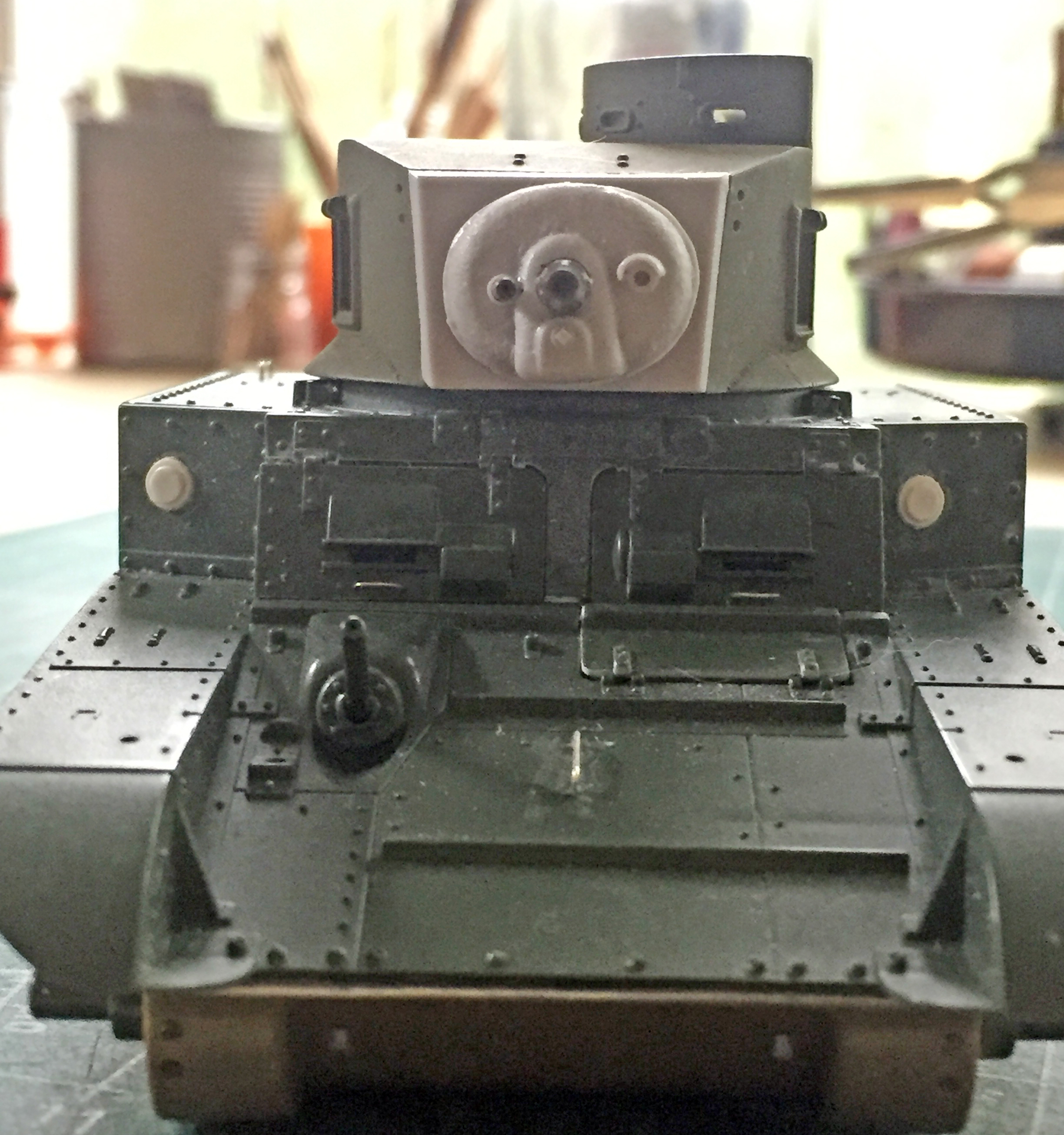
Then I dry-fit the turret bottom in place with the mantlet. I wasn’t quite pleased. The first thing I noticed was that the coaxial machine gun barrel isn’t parallel to the 37mm main gun; it’s closer at the machine gun’s muzzle:

Then I noticed that the resin turret front didn’t sit squarely, further exacerbating the misalignment of the gun mantlet. It’s all rotated slightly counter-clockwise:
I decided the easiest way to fix that was to shave material off the gun’s receiver (the body of the machine gun for those of you who aren’t gun-savvy). That would allow the gun to rotate and move the muzzle outward from the main gun. I popped the resin turret front off and filed it to fit the turret better:
Not perfect but it will suffice.
During the dry-fitting, I noticed that the eyepiece of the gunsight wasn’t sitting correctly. I popped the assembly off, sawed the eyepiece off, and reattached the gun sight’s body:

While the superglue was setting up, I added bolt detail to the air intake assembly on the upper rear hull using Grandt Line bolts (it’s like taking parts of gnats off a sprue and reattaching them…eventually…somewhere else):
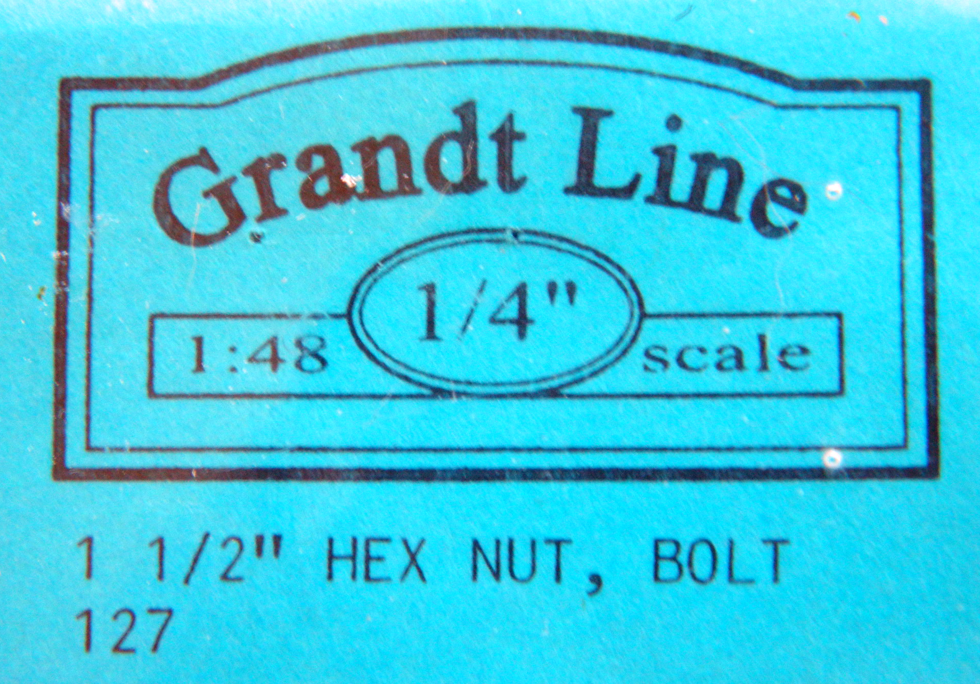
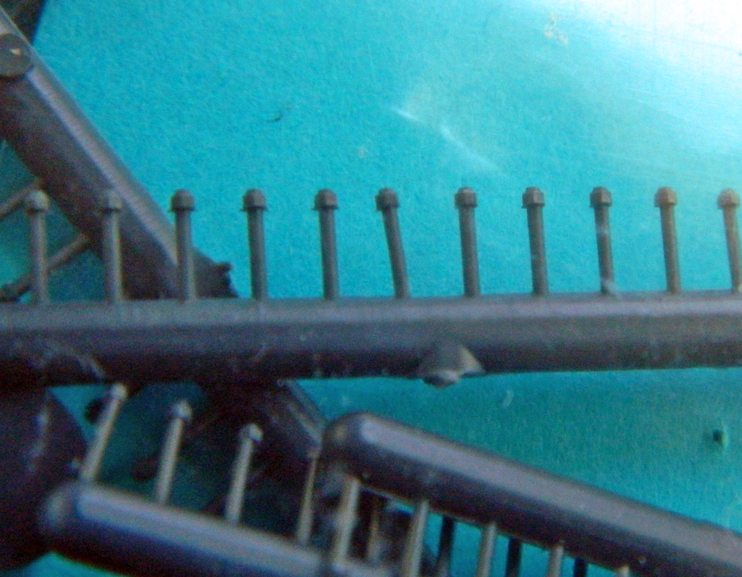
But they look great once they’re in place!
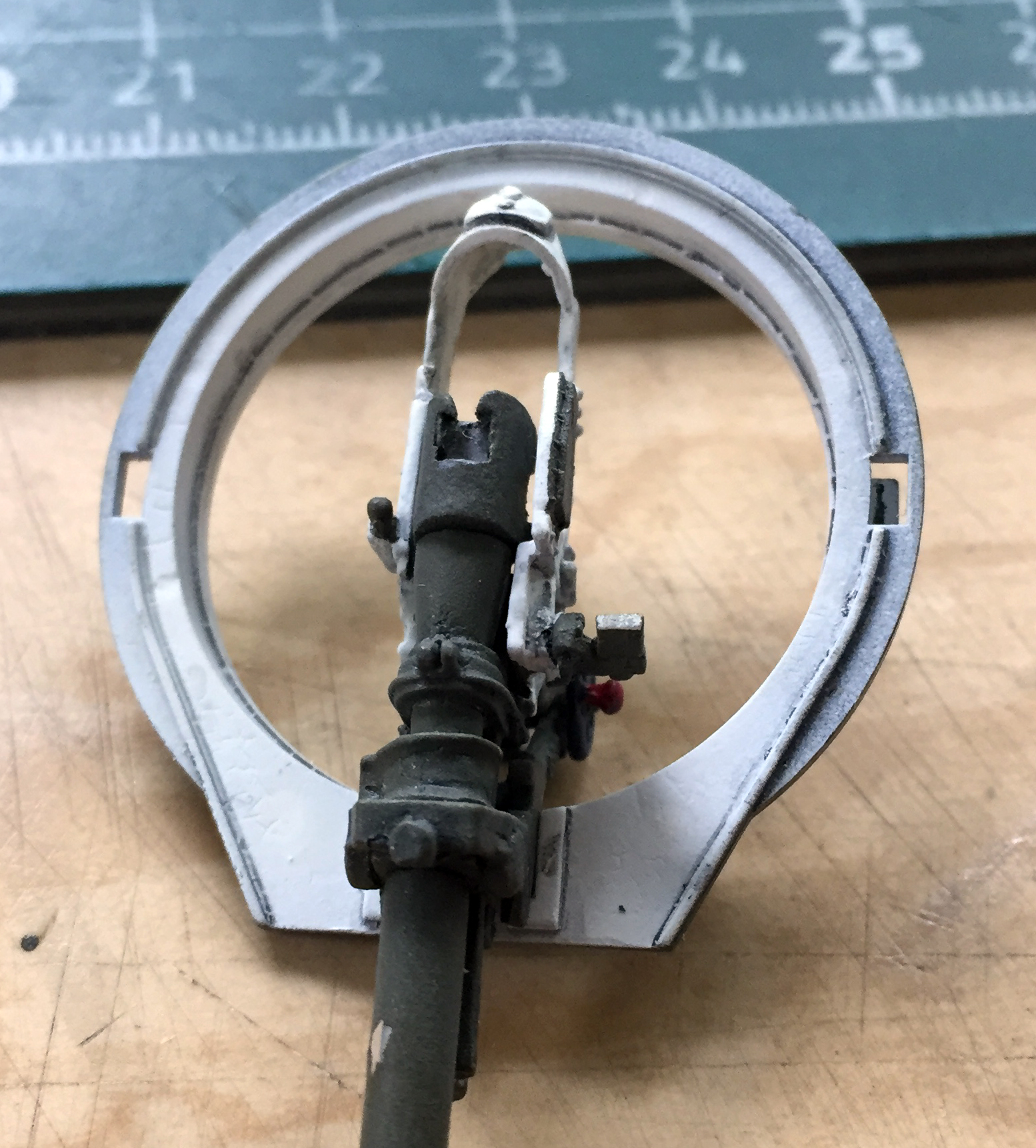
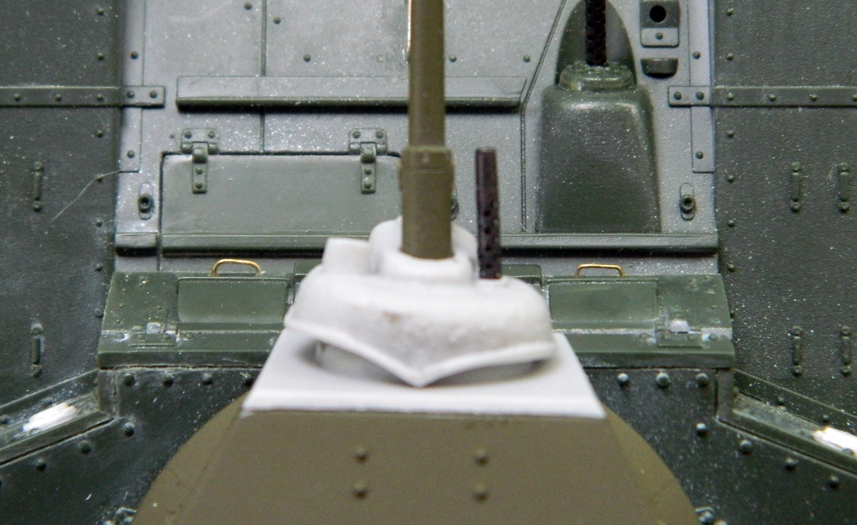
When I went back to dry-fit the mantlet to the gun assembly to make sure the gunsight lined up where it was supposed to, it wasn’t even close. On the inner face of the mantlet facing you, there’s a rounded projection. That’s where the gunsight is supposed to line up…and you can see how close it isn’t:
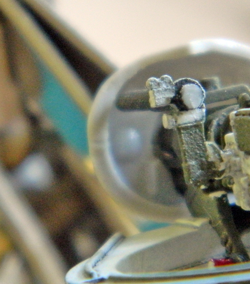
I had first considered that perhaps I’d erred and misaligned the parts as I assembled the gun parts. Nope. I checked the parts, I checked the alignment, and yet that’s where things ended up. (My respect for the person that mastered these parts took another solid hit.) I had to snap the gunsight free and trim the mount a few times before I got an alignment I could accept. That alignment required that the ammunition box for the .30 caliber (7.62mm), which was supposed to mount on the left side of the 37mm to instead be mounted on the turret ring next to the guns (unlike the .50 caliber (12.7mm) machine gun, the .30 caliber (7.62mm) can only be fed from the left side, requiring the ammo box to be mounted on the left side of the main gun with a chute above the 37mm to guide the belted ammo into the feed port).
No…that’s not in there correctly, but the cramped space inside the turret worked in my favor this time. Much of what had to be fudged and worked around cannot be clearly seen. Tight quarters and limited viewing angles can sometimes hide adaptations.
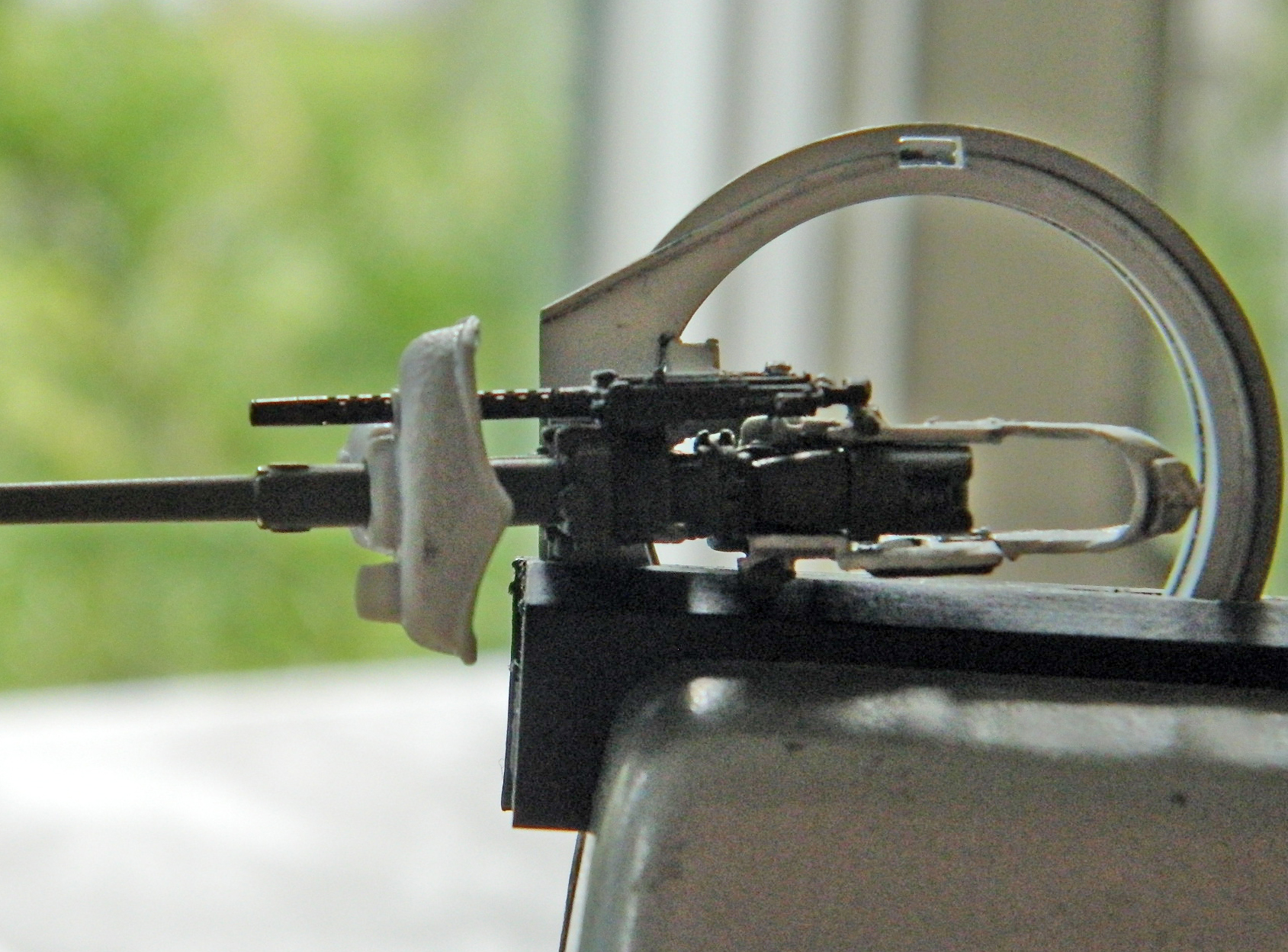
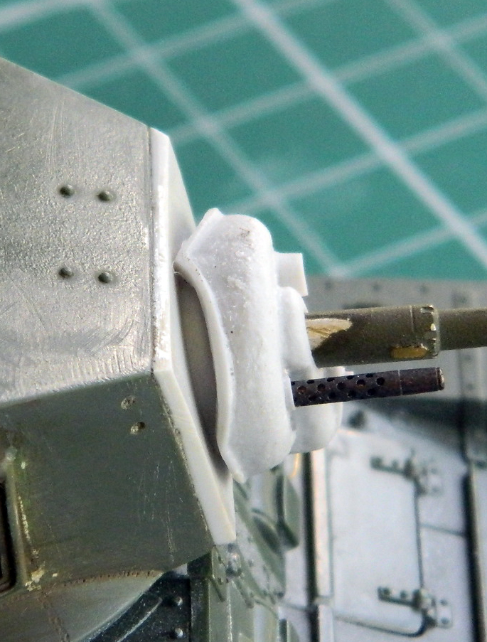
I discovered that the mantlet’s fit was a bit off. As it “fit,” the peak on the rear of the mantlet contacted the turret face while the barrel of the 37mm was mostly level. Well, that would certainly interfere with elevation:
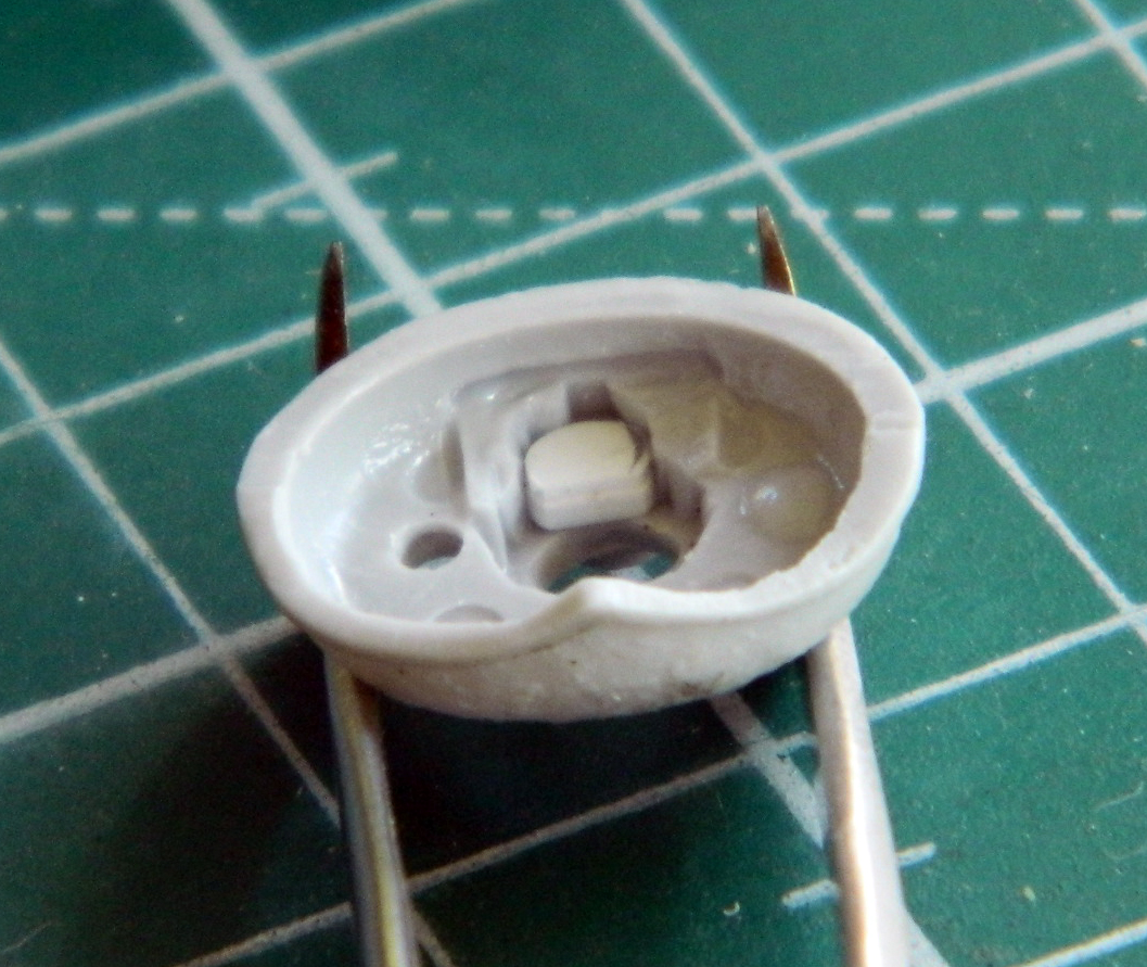
In order to move the mantlet away from the turret face, I needed to add a spacer (about .045″ (1.143mm) of scrap styrene) to its mounting point:
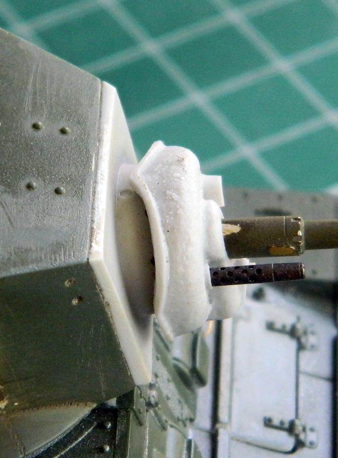
That solved the problem:
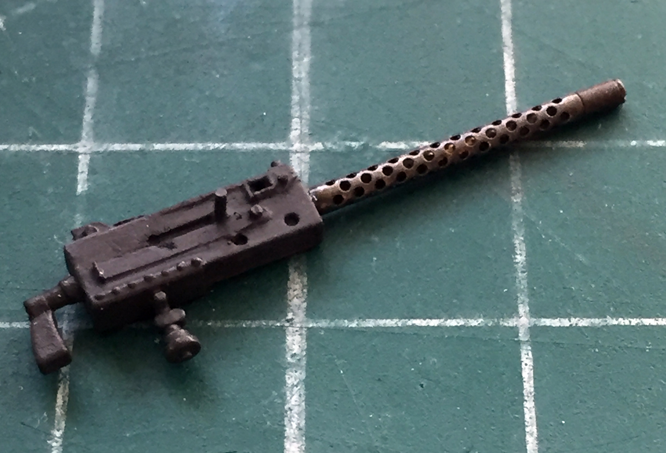
References show that the commander’s .30 caliber (7.62mm) was usually mounted in the Pacific (and at Guadalcanal, which is the locale I’m modeling this tank to represent). That gun is in the line of sight and I wanted to do something a bit more accurate than the kit’s part. I wasn’t especially satisfied with any of my options; the resin guns didn’t really fit the mount and the kit’s gun lacked detail. The easiest problem to fix was the absence of detail. Add some:
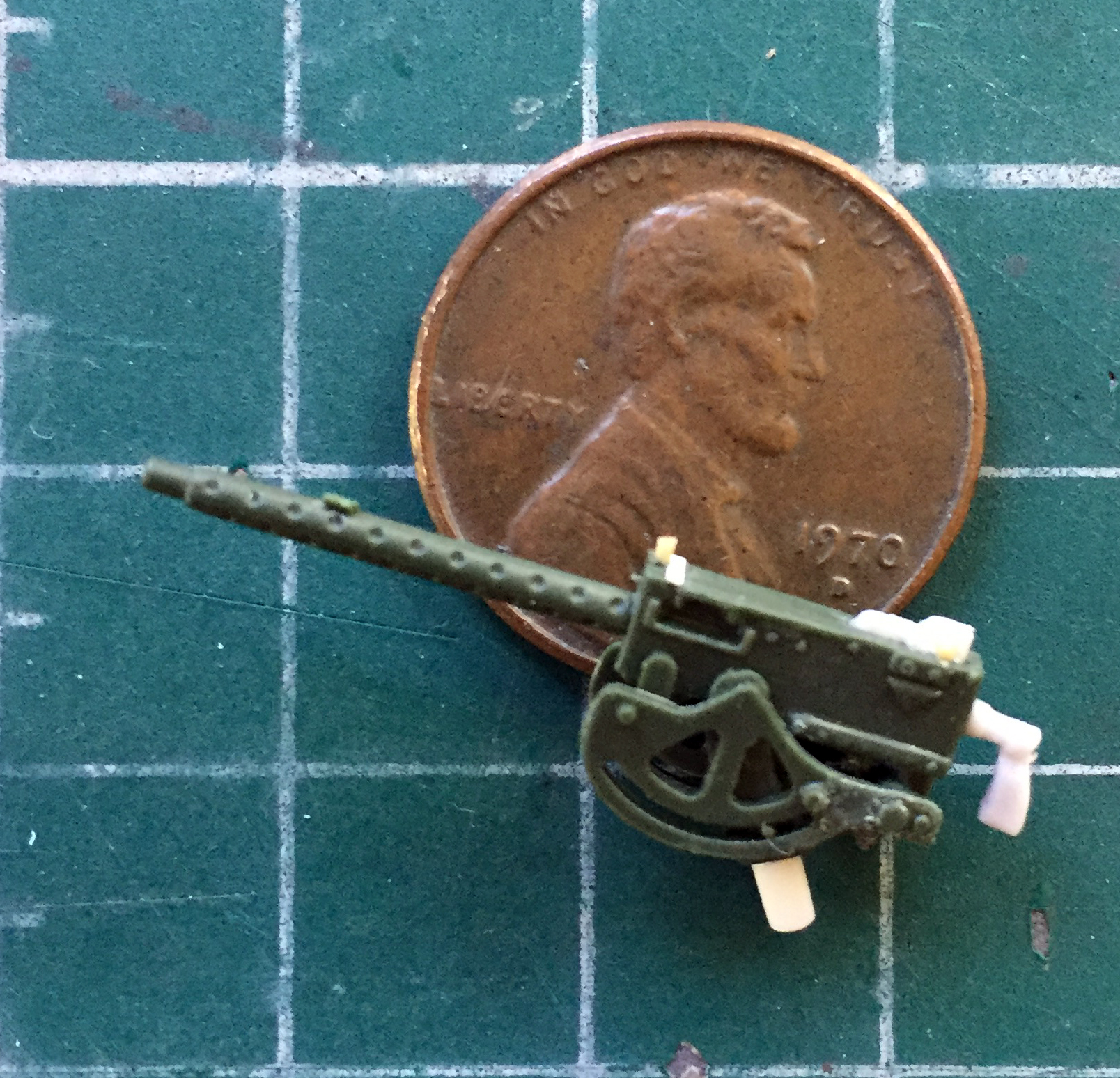
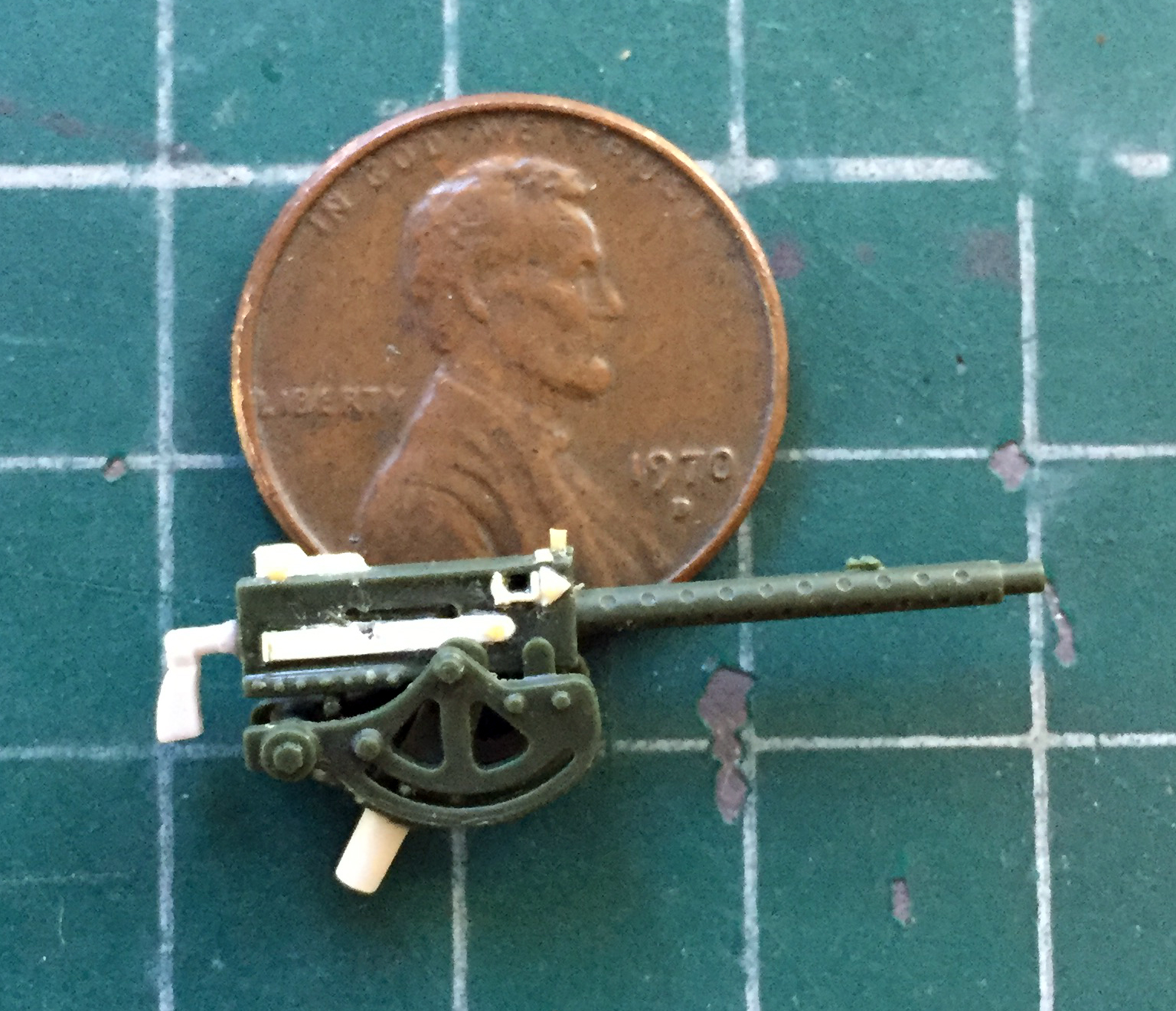


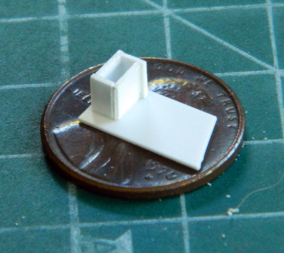
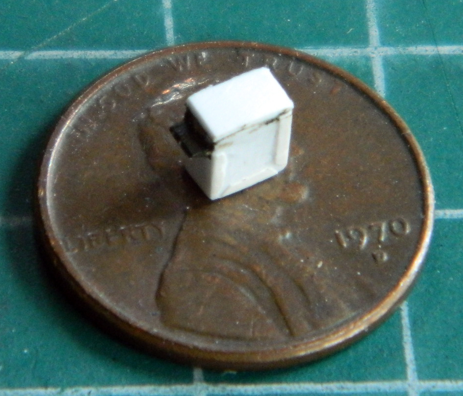
I’ve noticed that earlier in the war there was greater variation in gear than by the end of it. My assumption is that pre-war stock was used up and later in the war, equipment became more standardized for easier manufacture. I have plenty of what became the standard .30 caliber (7.62mm) ammo boxes on hand (500 rounds?), what I did not have was the 250 round box that was being used by the Marines in later summer of ’42. That required me to make one:
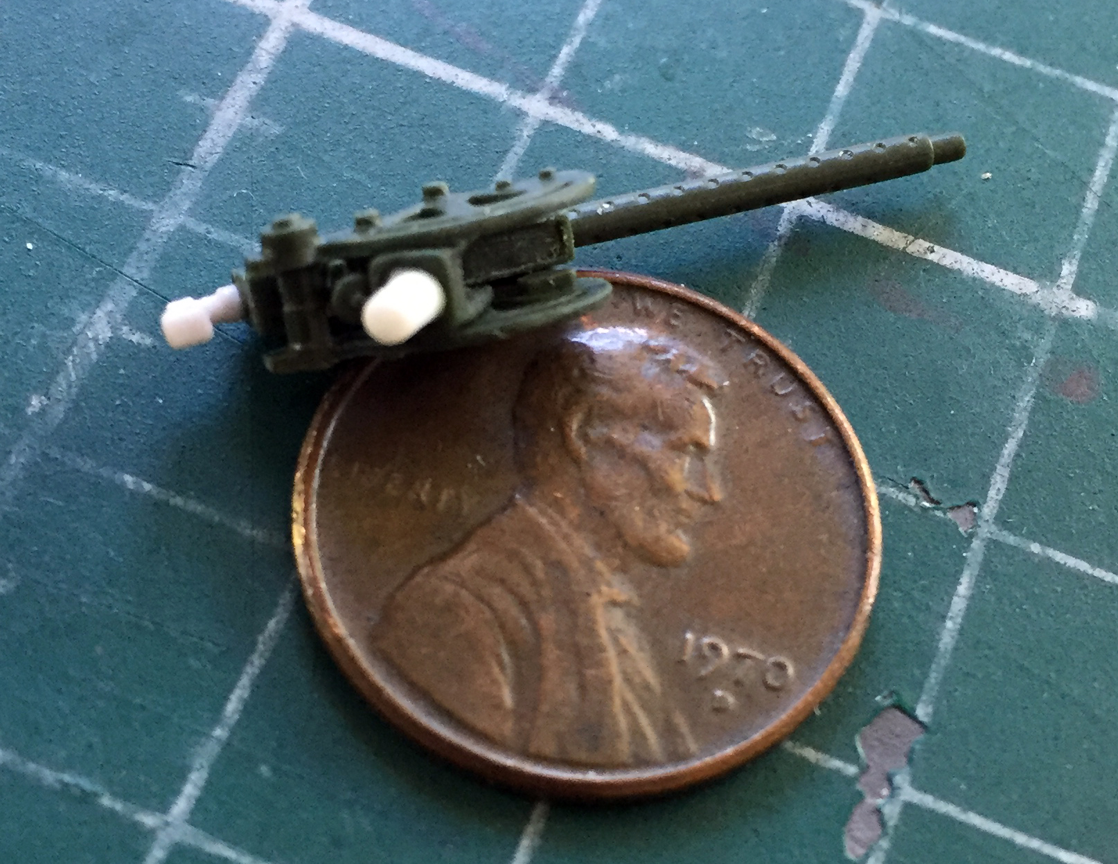
With the gun painted and the brass barrel installed, it just needs to be mounted in place:
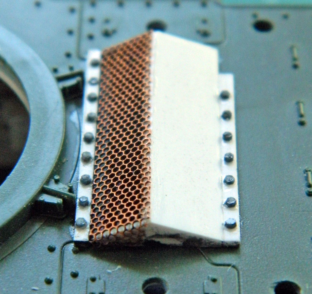
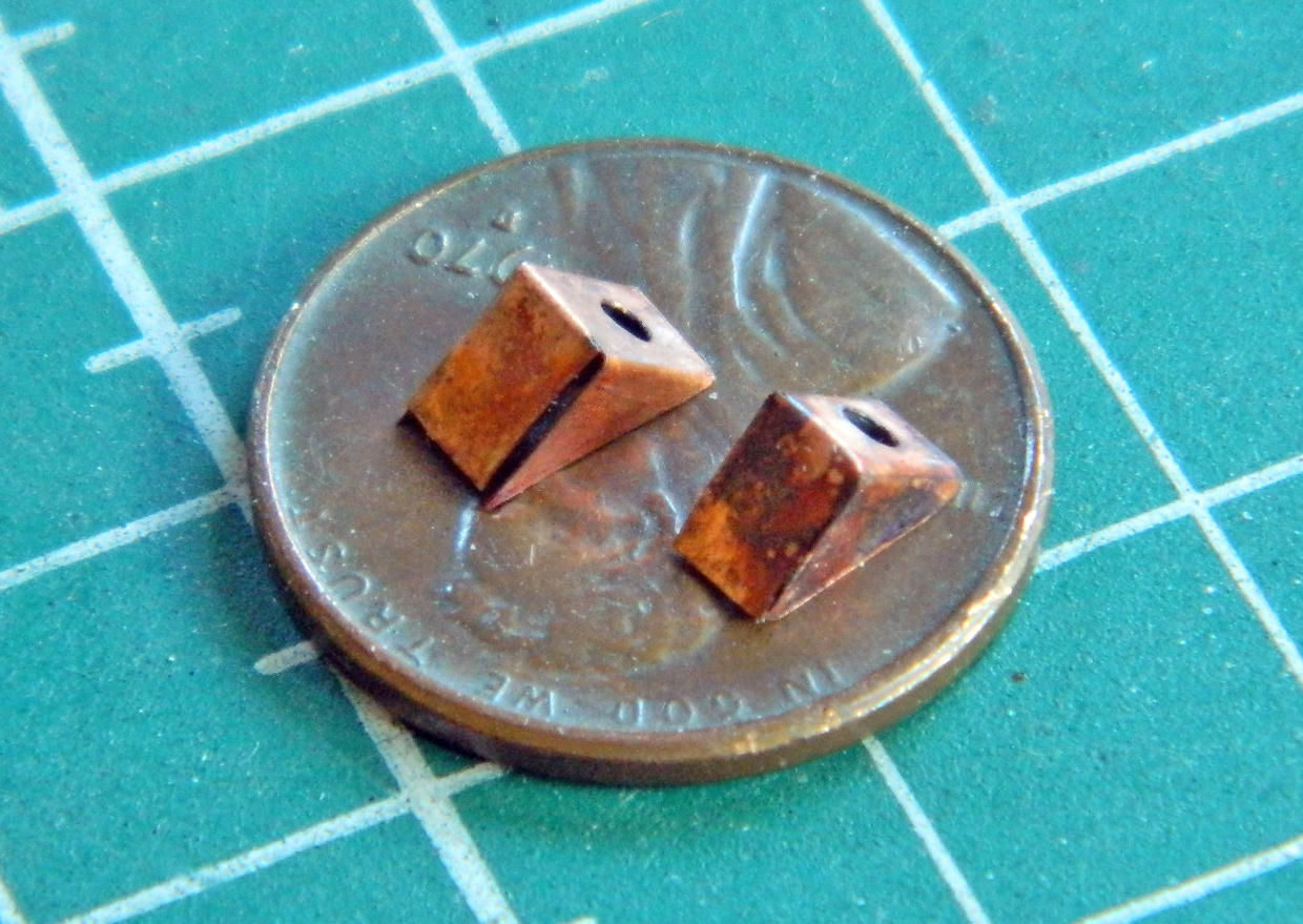
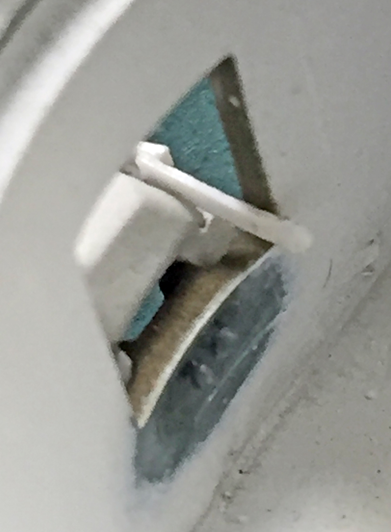
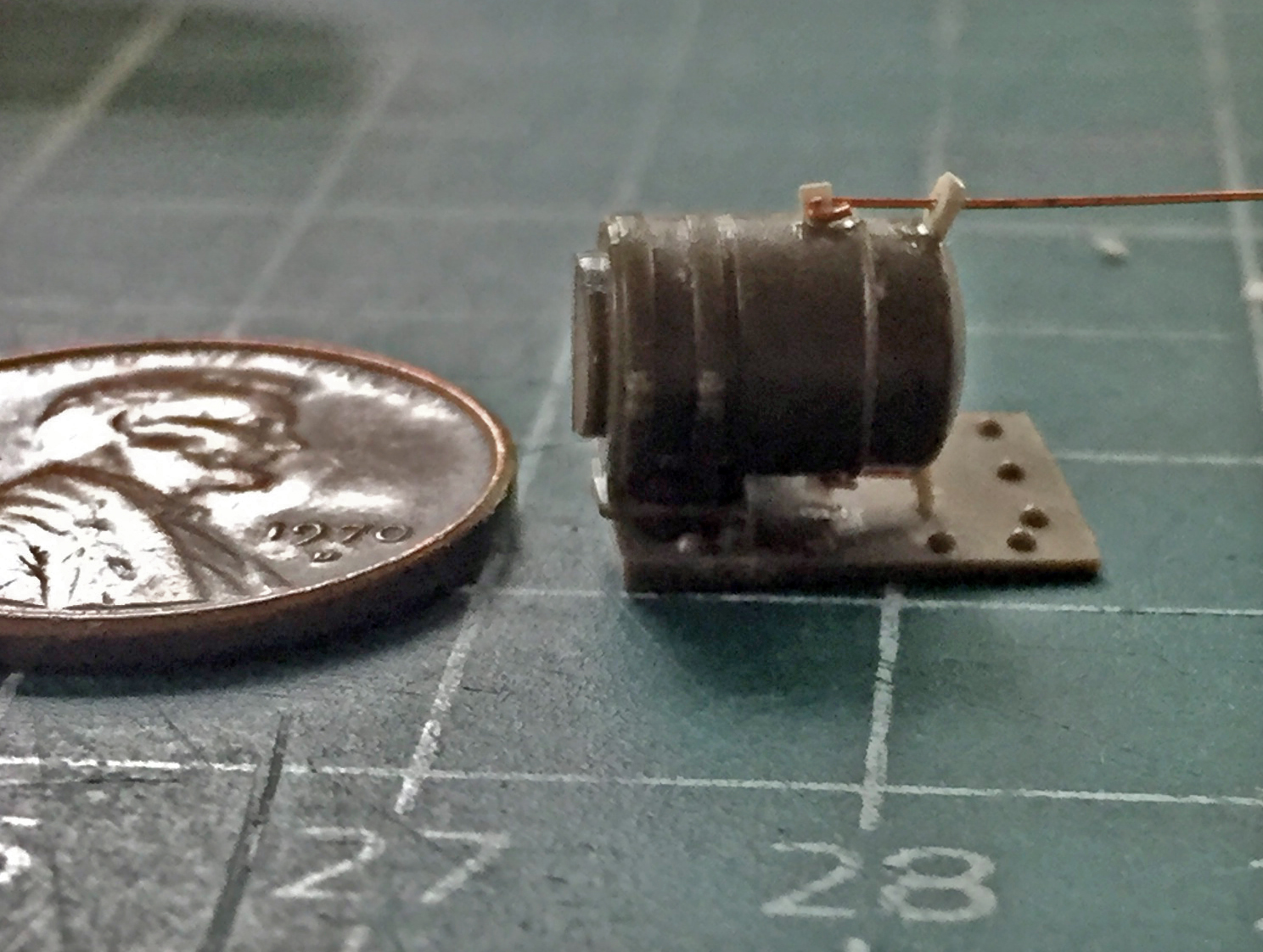
While I was wandering around the outside of the turret, I used .005″ (.127mm) copper shim stock to fold what looks like an unused antenna mount (because where would they put the second radio?!). As you can see, sometimes even something simple like this requires more than one attempt to get what you want:
This time when I married the upper hull to the lower hull, I decided that IF I needed to vacuum the fornicating bench, it could sodding wait until it was ass-biting clear:
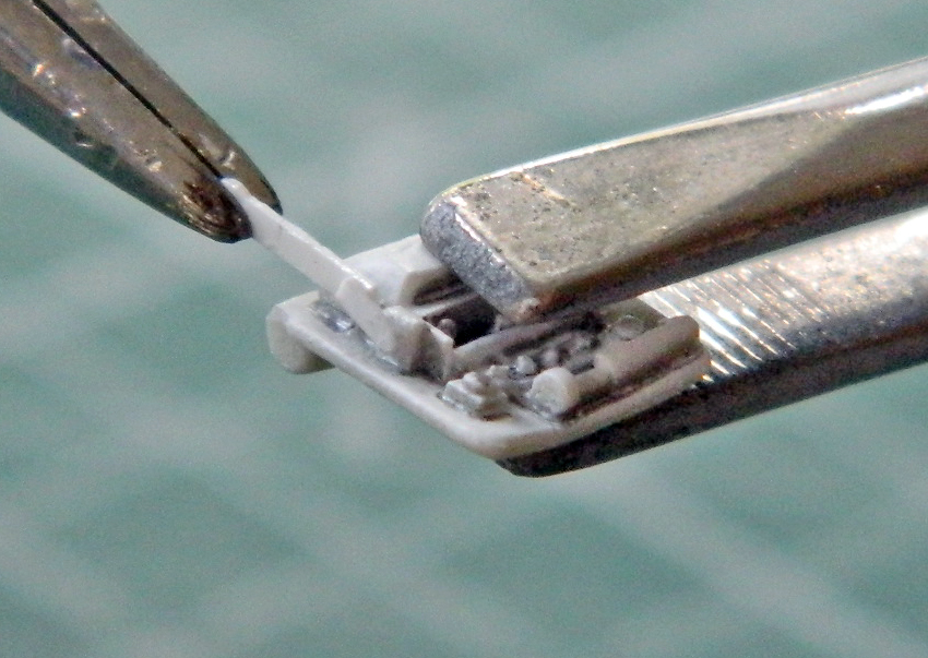
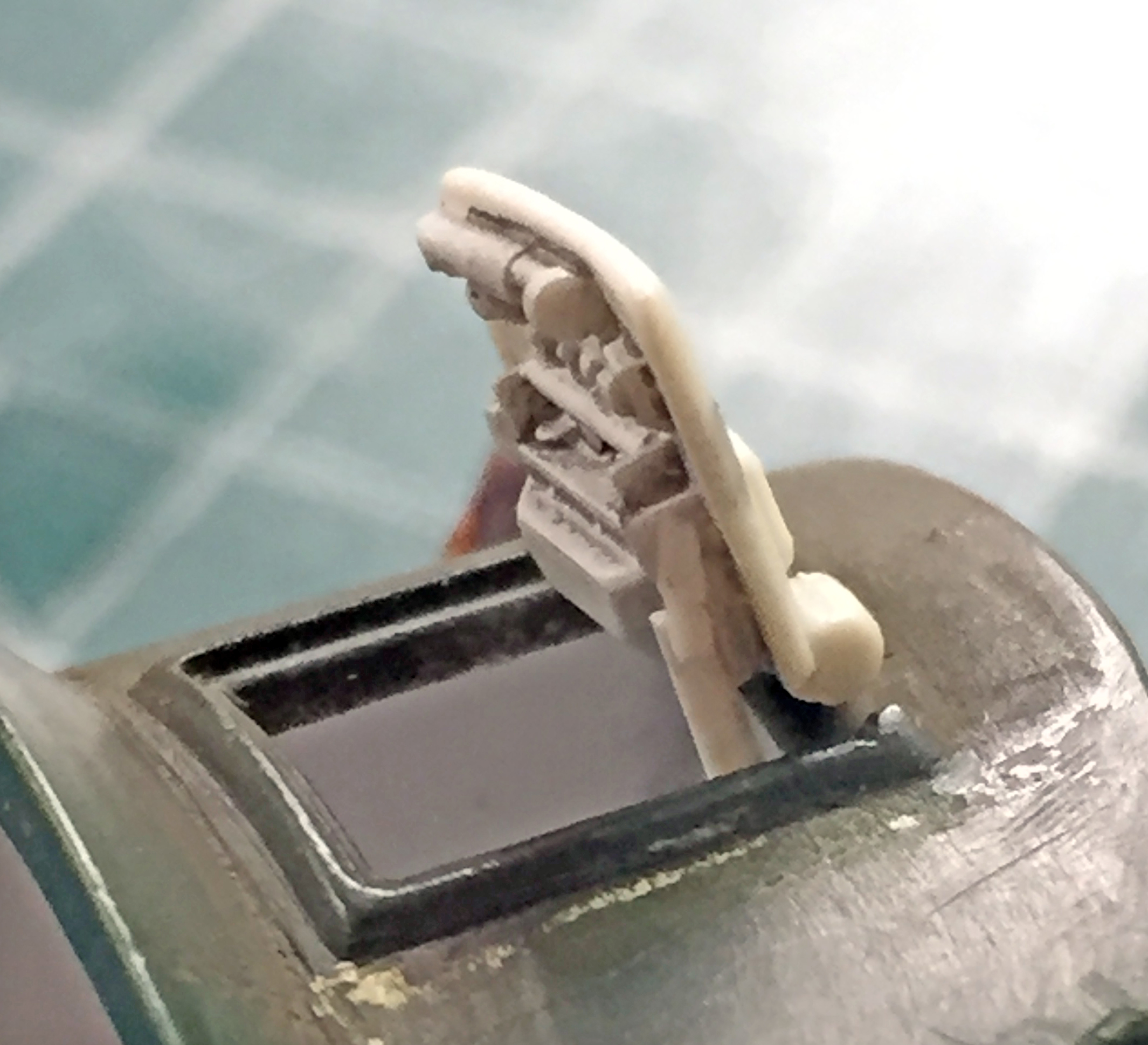
While the glue set up on the hull, I assembled the linkage that opened the pistol ports:

I also added more Grandt Line bolts because the mounts for the M3’s port hatches were bolted on unlike the Sherman’s, which were welded in place:
There will be more linkage added to the pistol port hatches later on.
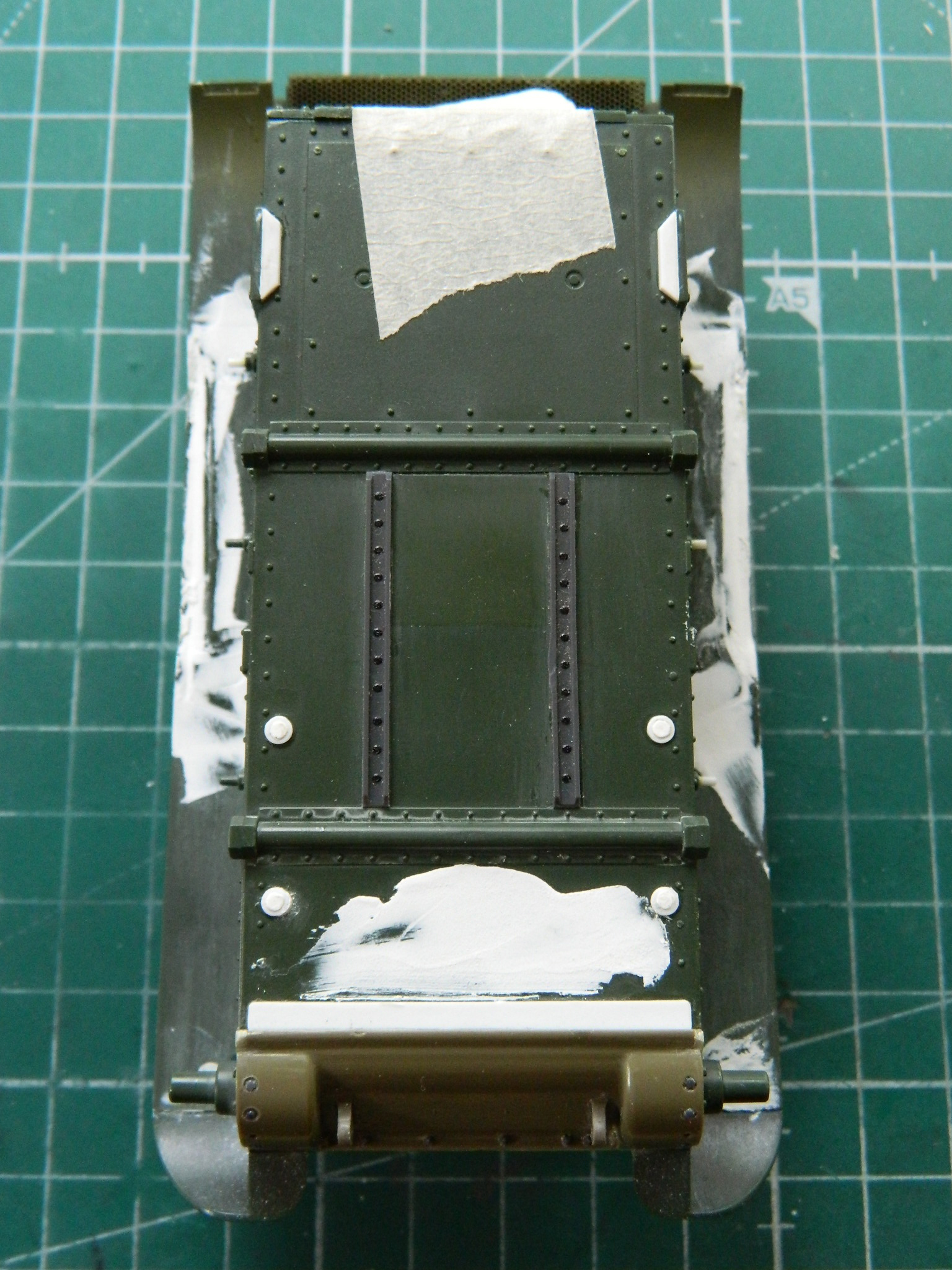
Since I had the upper hull in place finally, I puttied the underside of the sponsons to hide the gaps (again):
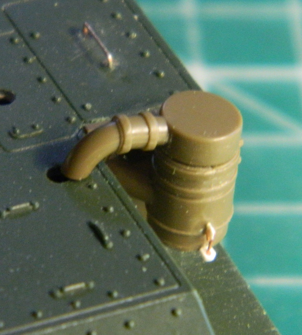
As I build, The Boys in the Back wrestle with various things that are problems in search of a solution. One of the (several) problems with this kit is certain details. It started with the headlight assemblies and then grew to encompass a few other things. The taillights were a bit off as were the air cleaner assemblies. While looking for something online that had nothing to do with modeling (yes…porn, again), somehow I ran across a video review of Tamiya’s new-tool M3 Stuart (because don’t all porn links take you to modeling websites?!). My take-away from that was that it’s a MUCH better kit than the hoary old beast from the early 70s and that due to how the parts were engineered, putting an interior in that kit would be a stone bitch. Fine if a silhouette model is the goal, though. Oh. And Tamiya’s headlights, taillights, and air cleaners were EVER so much nicer than Academy’s representations! In fact, they’re nice enough for me to have bought the kit as a donor kit. (Clearly, I need a life.) (Other than cruising porn.)
For instance… On the left is the mostly-assembled Tamiya air cleaner assembly, on the right is the Academy air cleaner:
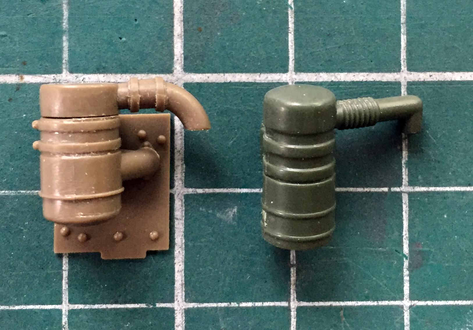
The Tamiya part is more accurate, intake ducting (the lower one on the right) is present whereas the Academy has none (and there’s no detail on the hull where this assembly goes in the Academy kit), the curve to the output ducting is accurate meaning I don’t have to fix the Academy ducts. Nice. But nothing is perfect (except maybe for stupidity) and Tamiya didn’t provide for the rods that keep the bottom of the air filter housing in place, so I added them:
There was a fair amount of fiddling alignment, application of glue, and waiting for the glue to set up so that I could continue. So while that was curing and waiting, I went back to work on the turret.
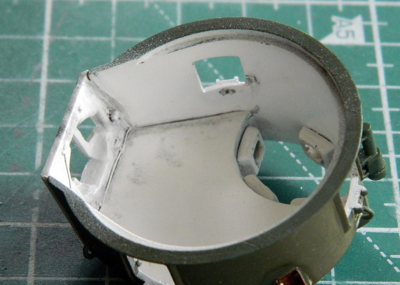
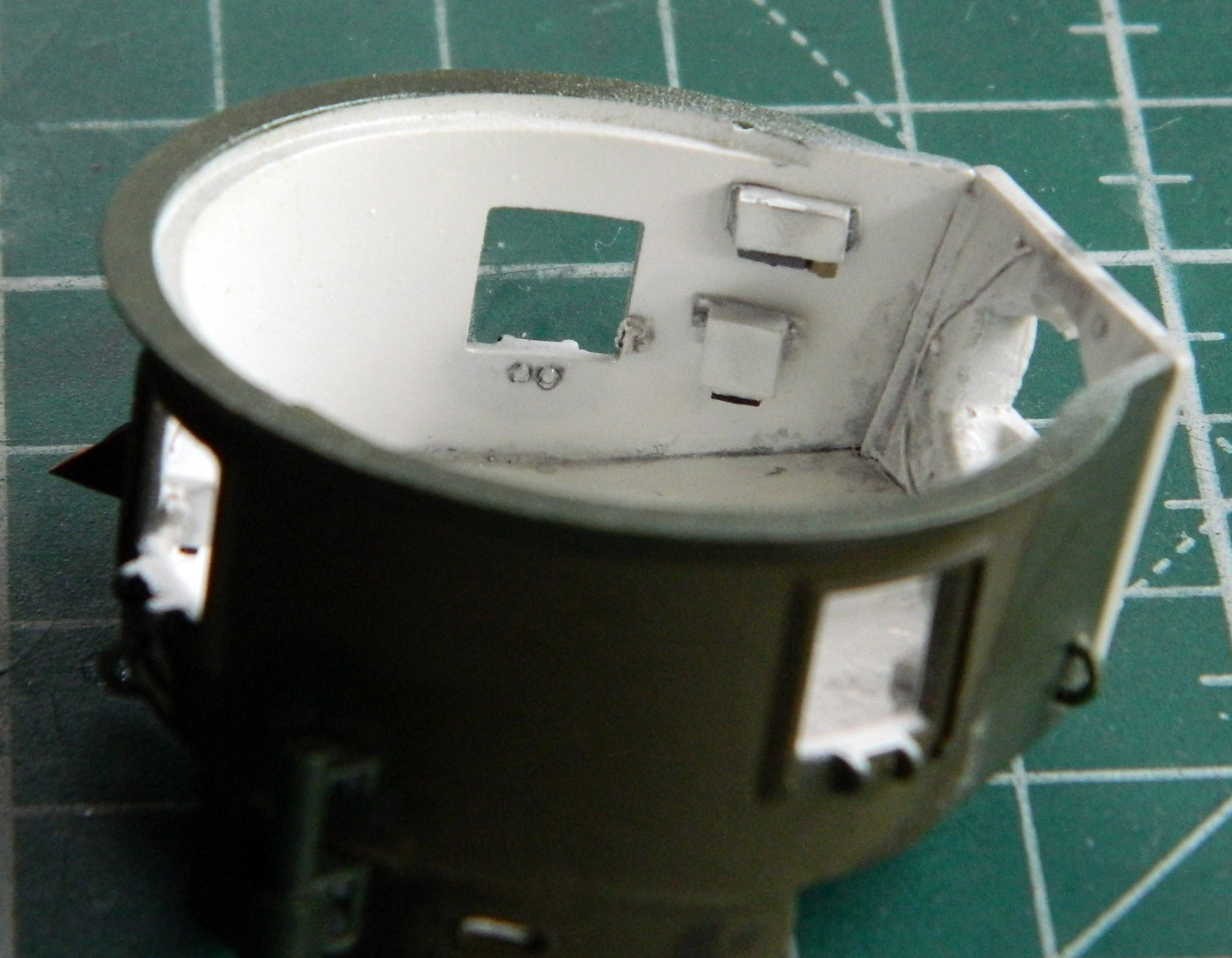
With the nuts, resin turret face, and the mount for the opening linkages for the pistol ports in place, I repainted the inside, gave it a coat of clear gloss, a dark wash, and a sealing coat of clear flat:
As that set up, I continued fiddling with the air cleaners:

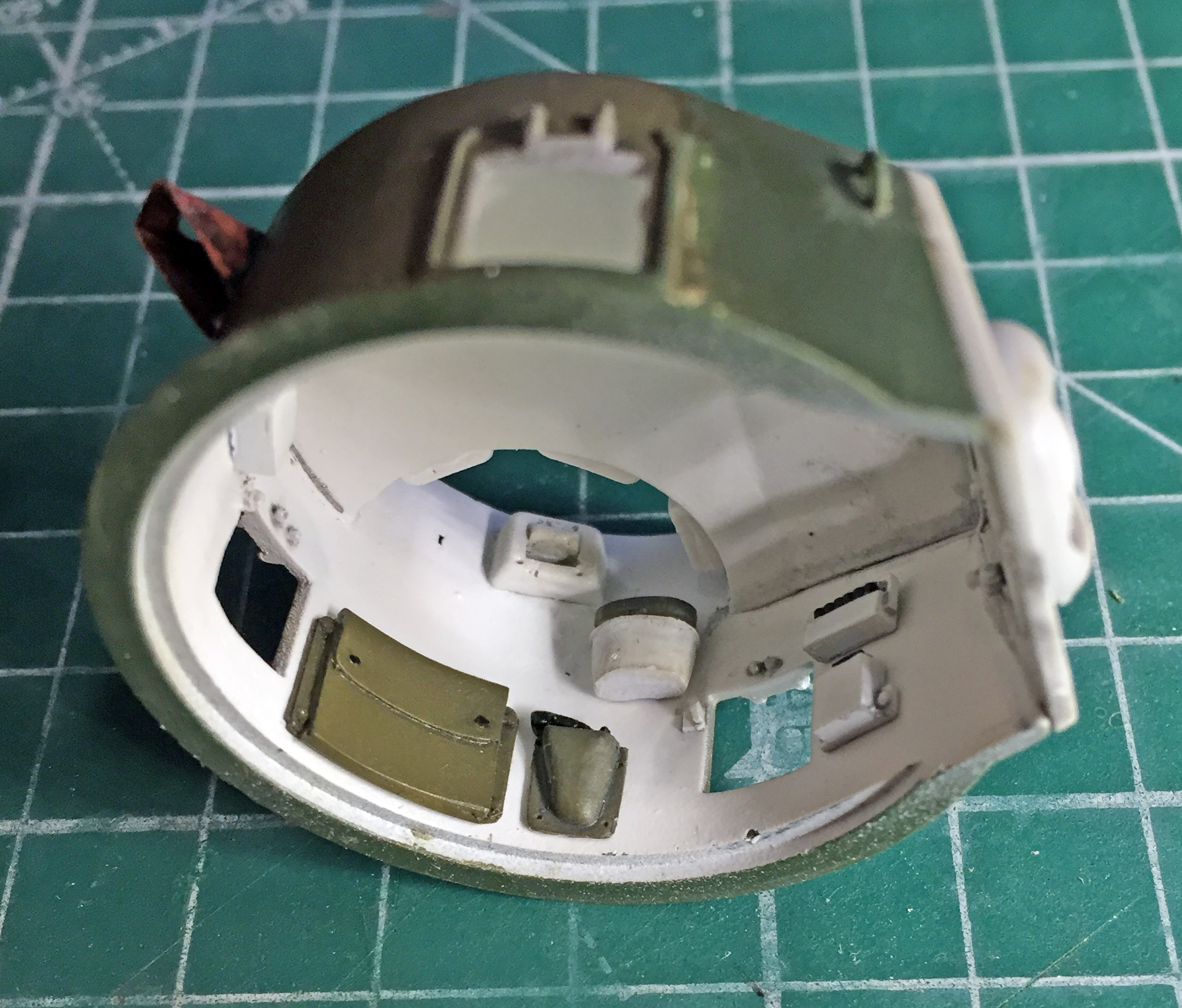
Just those four small additions took enough time that while the glue on all of those additions set up, I populated the interior of the turret:
Adding more detailed air cleaners would take a bit of surgery. As you can see, just gluing them in place would result in this section of the hull being far too thick (and later on I would definitely need that missing space for something else):
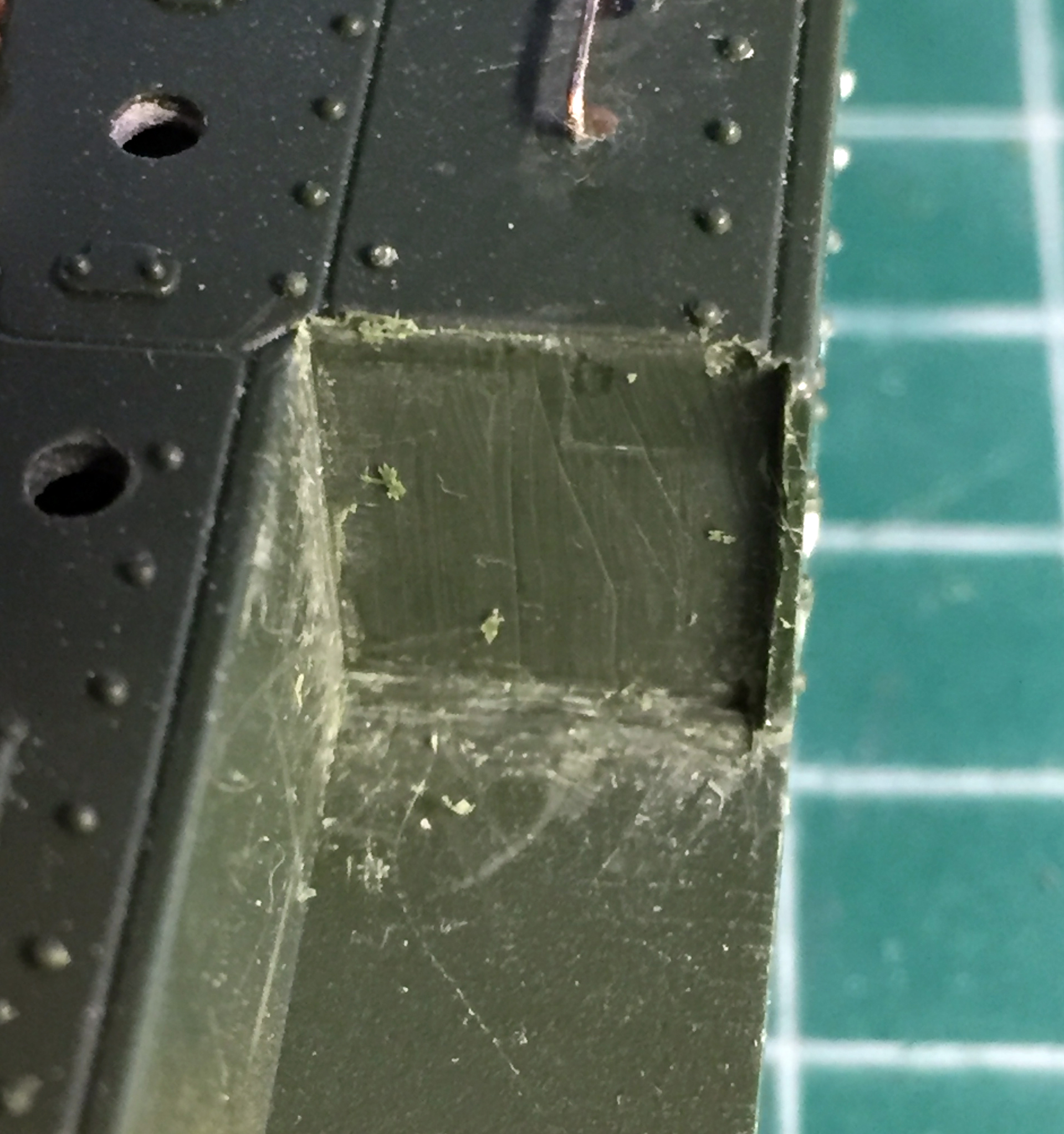
With that just held in place, I traced the edge of the new part on the kit to see how it could fit. If I could excise the plastic between the scribed line and the hull, I figured I could socket the new parts into place without losing the space I’d need to mount the sponson storage boxes (and this photo shows how bereft this area was of details):

First I hogged out the plastic with my Dremel to get it close:

Then I used a freshly sharpened chisel blade to scrape things to a more accurate configuration:
The new part was dry-fit several times with resulting adjustments until a pretty good fit was achieved:
I also checked to see how the new ducting would line up with the hole in the engine cover, which it does not:
Right, so, that hole got filled. I chucked a piece of sprue into a variable-speed drill and used a file to taper it slightly and then stuffed it into the hole and glued it:

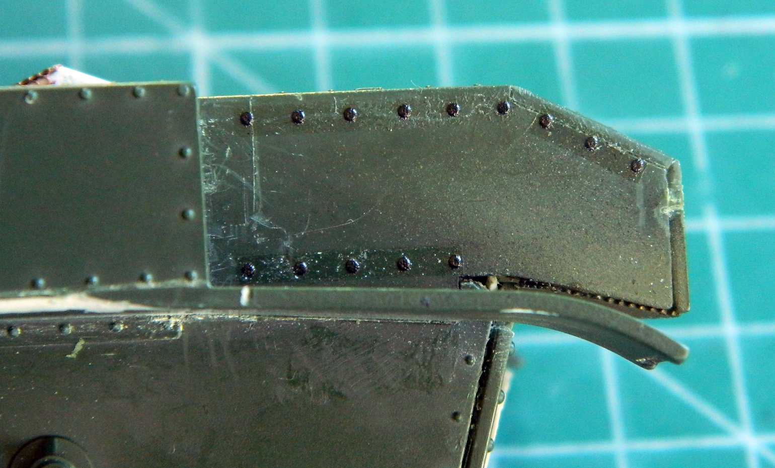
I didn’t know how much of the missing rivets would show so I added some Archer resin decals (great stuff, that!). I discovered later that most of these would never be seen:
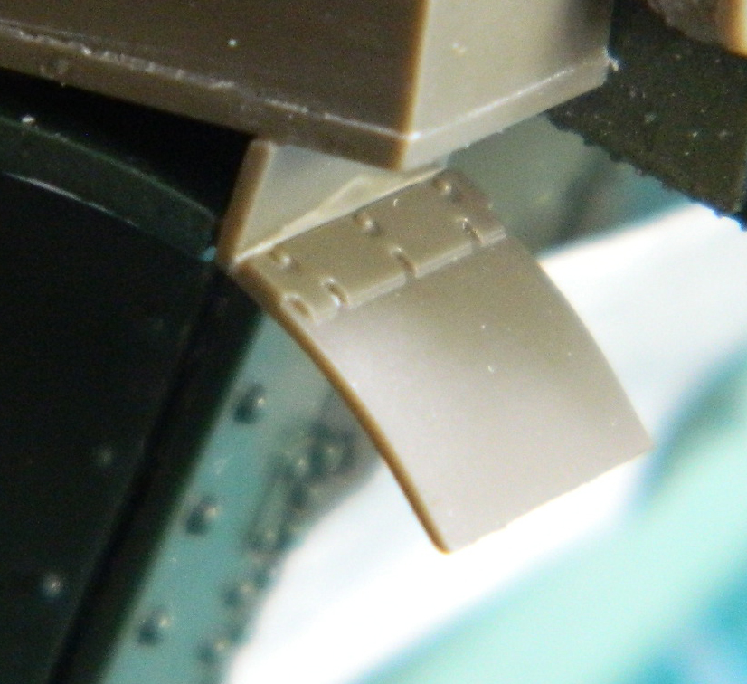
The detail for the mud flaps provided by Tamiya was better than Academy’s so I cut off the rear of the fender to add the Tamiya part:

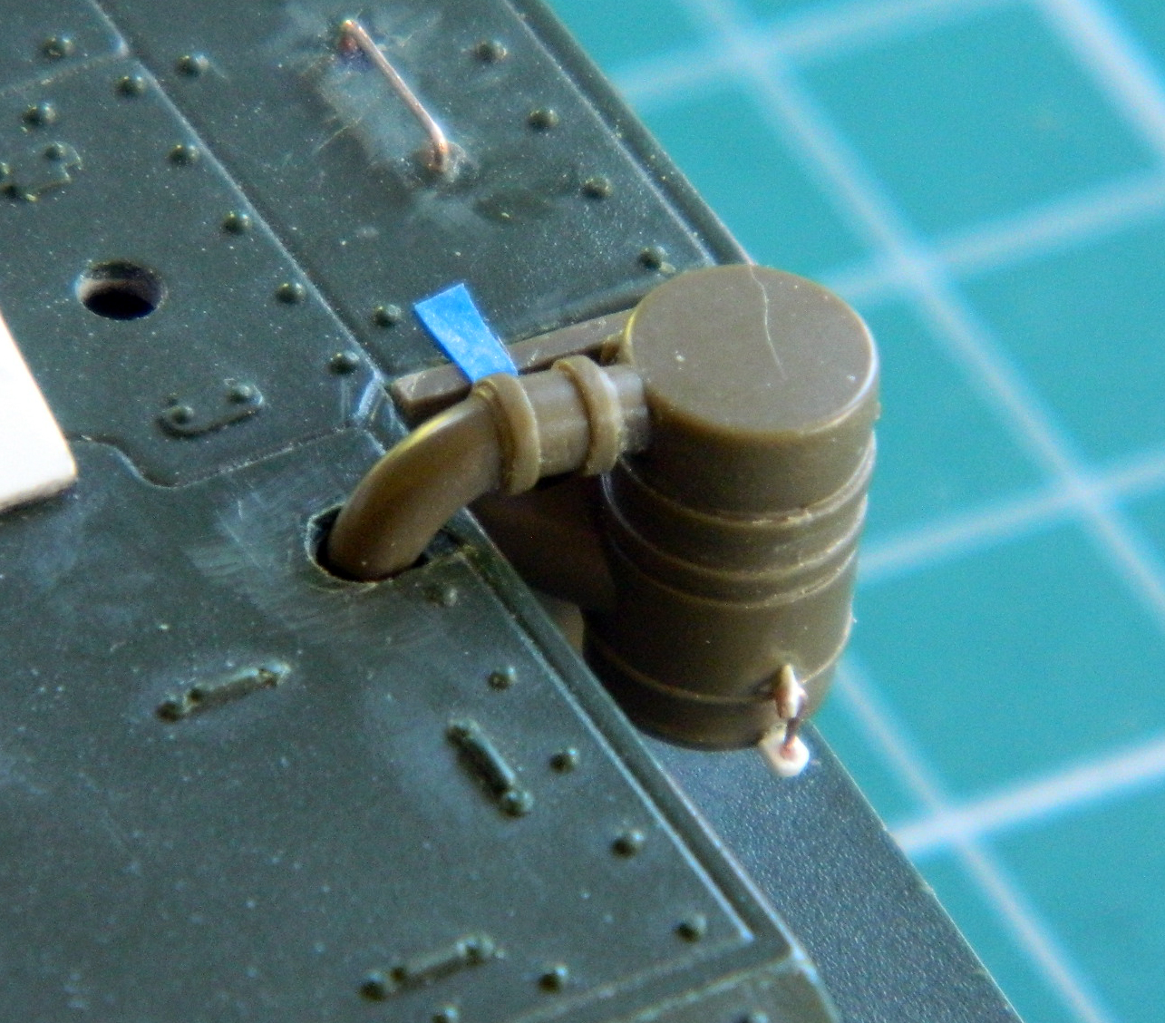
I dry-fit the air cleaner assembly to determine where the new access holes had to be drilled and then checked alignment. Satisfied, right after this photo was taken I glued both air filters in place:
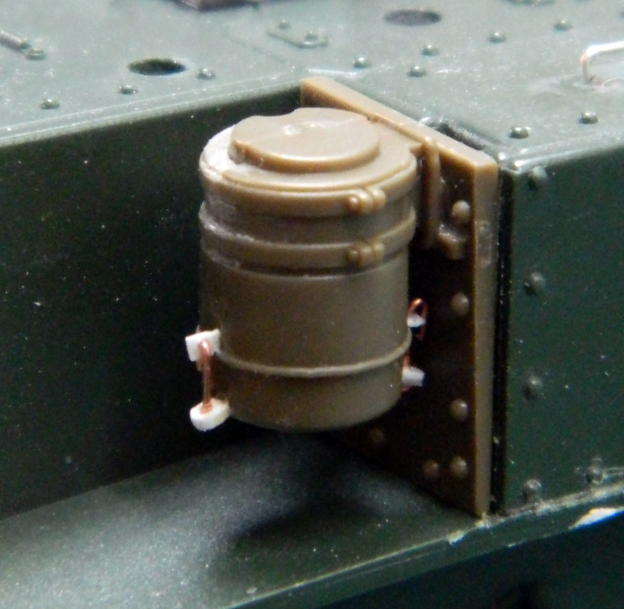
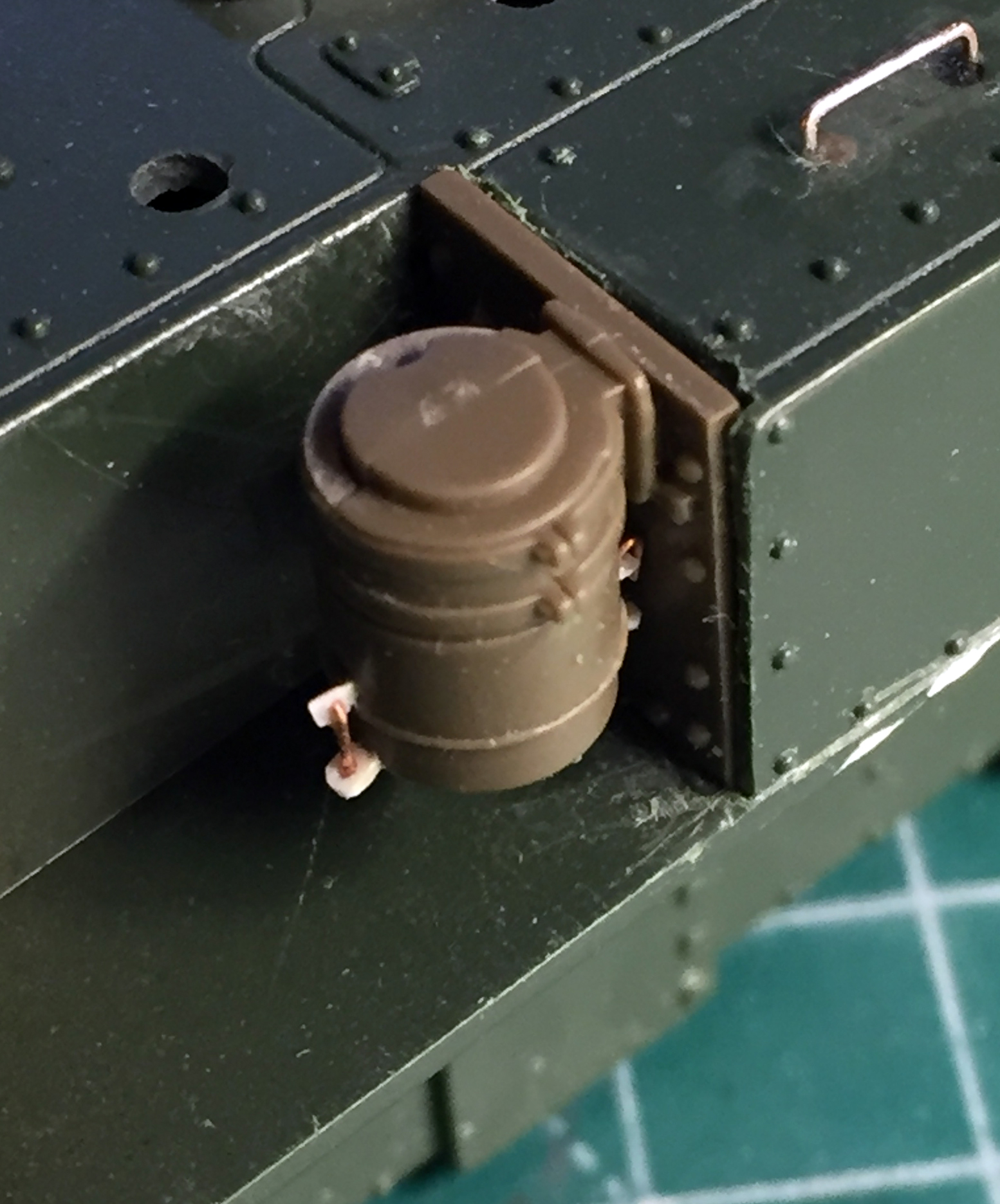
With those permanently attached, I added the sponson storage boxes and the mud flaps:
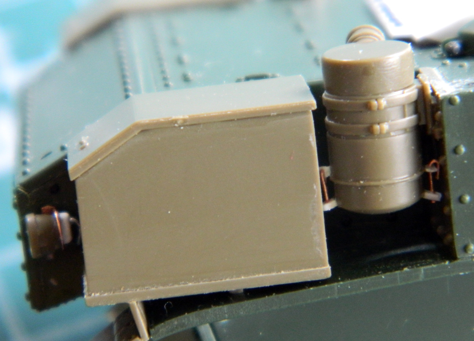
I also removed the kit’s taillights at this point. I used the Tamiya parts, made mounting brackets from .005″ (.157mm) copper shim stock, and added detail to the back of the light and used some .015″ (.381mm) solder as wiring conduit (which can also be seen in the above photo):
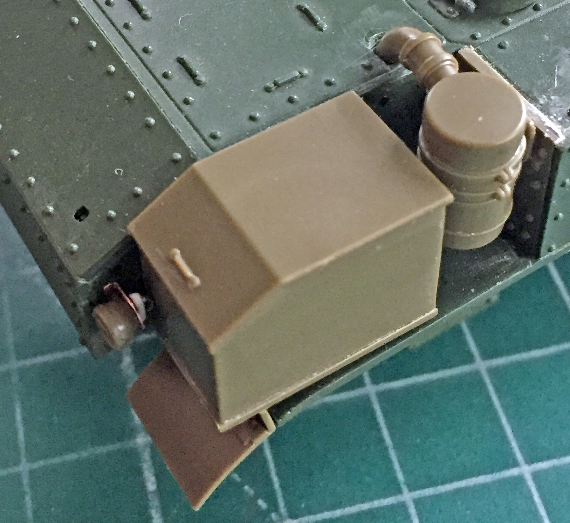
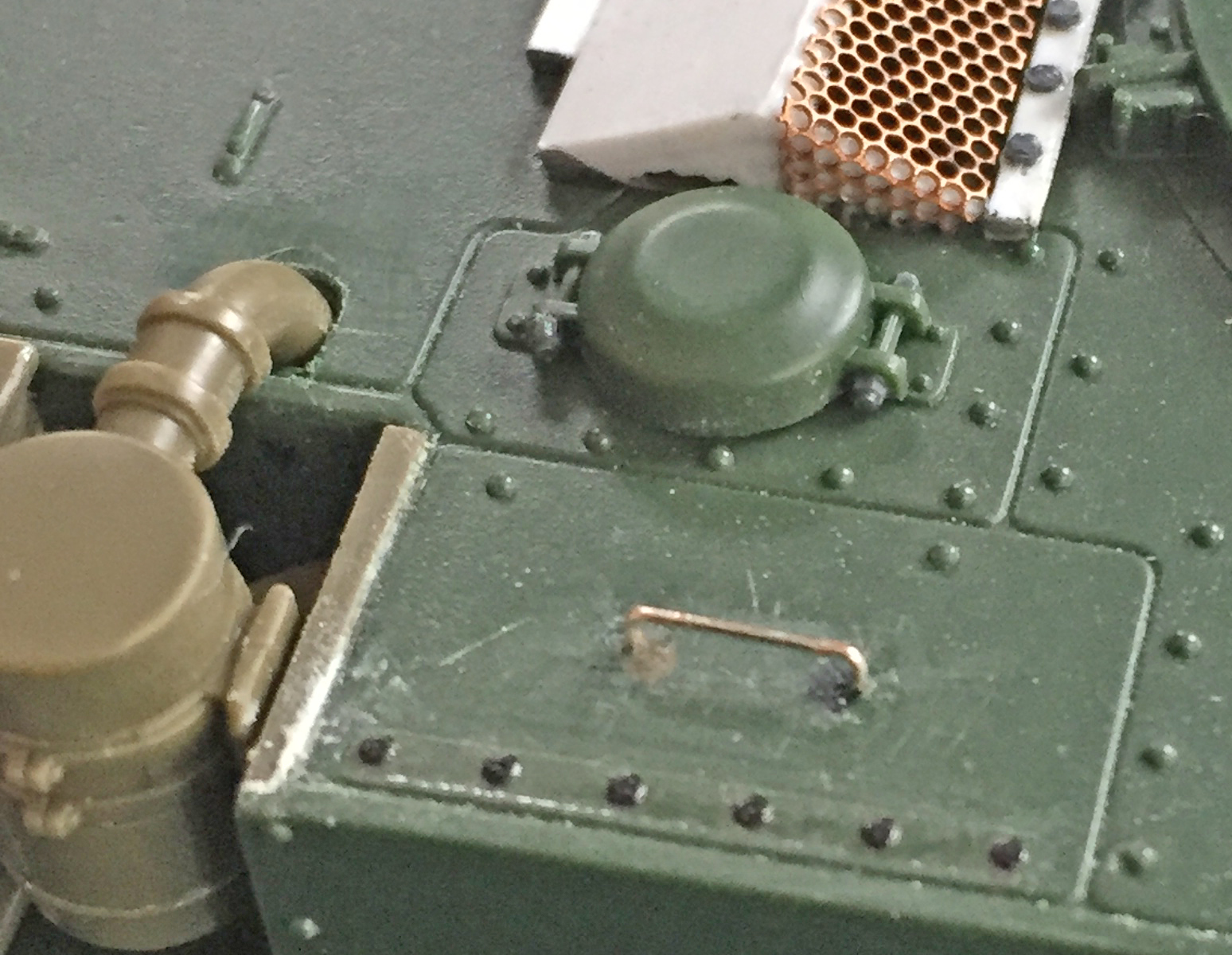
The armored fuel cap covers have distinctive and evident bolts holding them closed. The kit’s covers had the bolt length but no nuts. Once again, Grandt Line to the rescue:

I wanted to improve the detail of the sponson storage box closures. Modern restorations of the M3 seem to favor latches. I don’t know if later variant M3s had them but my references show the earlier ones used straps and buckles.
::sigh::
So I used a buckle from a Verlinden Sherman detail set (did I mention I’m gonna miss that guy yet?) and some lead foil to replicate (TEDIOUSLY) the buckle/strap arrangement. I cut away the molded-in cleats and used small cleats from TMD resin:
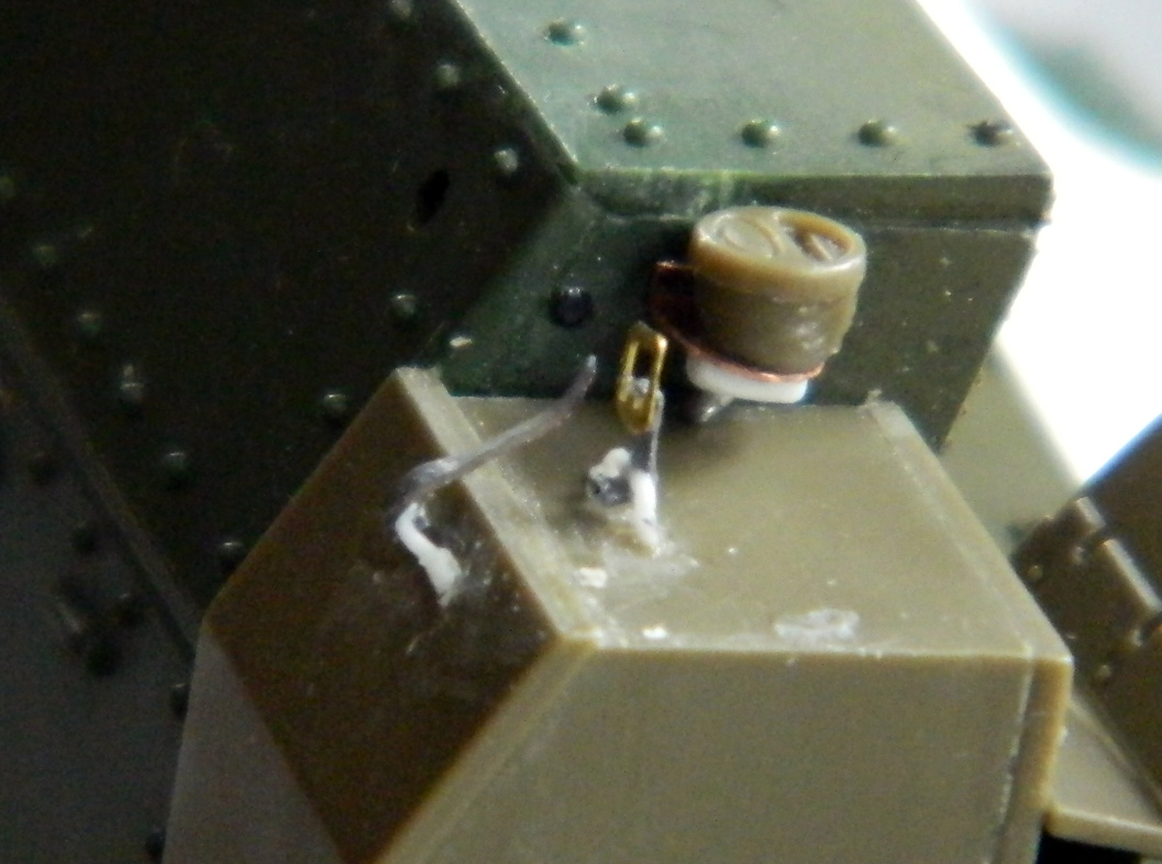
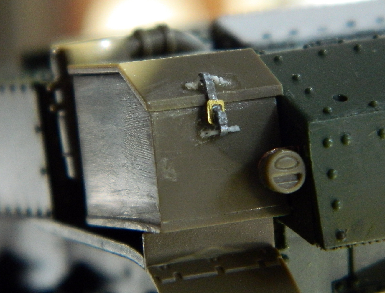
Though FREAKING TEDIOUS to do, I like the result. Now to do the other side…
