

Once upon a time, if a modeler wanted to add an engine to an M4, M4A1, M18, etc., the only aftermarket set I could find was produced by Tank Workshop (TWS). As with all things, time brings changes. TWS is up for sale (last I checked, dunno if it’s been sold) and isn’t (or wasn’t) answering emails regarding acquiring any of their items. So that source for the Continental R975 has dried up.
During my build of MiniArt’s #35206 M3 Lee Early Production (with full interior, including an engine and engine bay), the engine parts impressed me. I thought it would be a grand idea if MiniArt produced a stand-alone kit of just the engine. Then it occurred to me to check their website and check…and YES THEY DO! It was released in 2019.
I have a few more Shermans in queue and there are Tamiya’s #35190 Early Production M4, and a couple of M4A1s (both Asuka). I haven’t tossed the coin yet to see which of the three I’ll add an engine to, but thanks to MiniArt, now I can! (And yes…one of their R975s are on the way). The R975 kit #35321 has the same sprue layout as the engine provided for the M3Lee kit. I’m reviewing the M3’s engine as it’s the same as the R975 kit.
The engine parts are on four frets. The parts are nicely (and as you’ll see shortly, almost too nicely) molded showing excellent and comprehensive detail. The reason I say “almost too nicely” is because the kit also supplies oil, fuel, and an air-bleed line and they are very finely molded, AKA very thin. As they were packaged in the kit, insufficient care was taken to keep almost every of those very thin lines from breaking (all the parts were packed in the same cellophane bag). If you get this engine kit, before you remove any of these parts from their sprues, check closely to see if any of them have broken. It’s so much easier to glue the broken lines back together while they’re still on sprues, if only because gluing them on the sprues maintains their alignment(s). Hopefully MiniArt will package these fragile parts better in the stand-alone kit than they did in the M3 kit. DON’T use nippers to remove them from the sprues or you will break them. I used a very thin razor saw (RB Products) to remove the parts from the sprues.
The engine set supplies any part I could think of, mostly, including the wiring loom ring (if you want to add spark plug wires, you’ll need to add the stubs where they emerge from the wiring loom ring as they are not molded on. I used .025″ (.635mm) styrene rod to replicate them and to mount the individual plug wires, I drilled out the ends of the stubs using a .016″ (a hair larger than .381mm) so that I could use .010″ (.254mm) solder as the individual plug wires. They also supply both early (for M3s) and later (for M4s) air intake trunks and exhaust manifolds.
Fit is good but requires patience to add a few parts. When adding the rocker arm covers, one part (Dn3) has a line that connects it to the adjacent rocker arm cover (Dn2). Glue the Dn2 part in place first! The line that connects the rocker arm covers is very thin and seeks any opportunity to break off. By gluing Dn2 in place first, when you add Dn3, you will not only have support on both ends of that line, it lessens (and of course never removes) the chances to snag it on an errant finger and snapping it off. You will need to diddle these rocker arm parts a bit once they’re glued on to achieve a good fit:

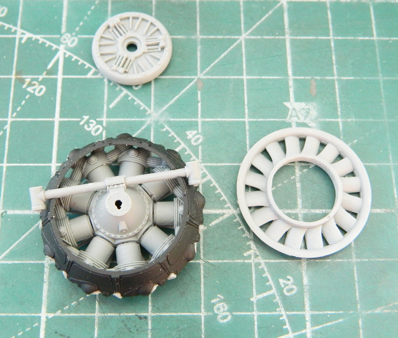
The paint call-out would have you paint the crankcase gray. Don’t bother. Once the shroud, clutch, front engine mount (the crossbar), and fan are in place, it’s impossible notice it no matter what color you paint it:

Overall, the fit is very good. Yes, you’ll need to diddle the rocker arm covers for a better fit, but it’s not difficult to do.
The exhaust manifolds require care to mount correctly. DRY FIT FREQUENTLY so that you have them aligned correctly and attached where they should be. On the actual engine, the manifolds have what look like sheet metal brackets that support the manifolds once in place and the kit doesn’t supply them or attempt to replicate them. I used lead foil to replicate them.
There are a few other parts you need to add if you’re after a really detailed engine. You’ll need to add the end of the throttle linkage to the carburetor (a small piece of wire, nothing involved as most of the throttle linkage lives under the engine and can’t be seen) and a fuel line to the fuel pump (again, I resorted to .010″ (.254mm) solder for that).
As of this writing, I haven’t completed the engine. Before I can add the generators, carburetor, and fuel pump, I have to add the rear engine mount. I’ve dry-fitted the remaining parts I have to add and the “very good fit” continues with them. (You can go to “Behind the Scenes” to see how final assembly and installation into theM3 works out.) (Later…once I’ve gotten to it.*)
I am very pleased with how this engine went together and even more pleased at the accurate representation of the R975 engine. Yes…there are some bits you could add. I mentioned the stubs on the ignition wire loom. There are also the throttle linkage to add and the fuel line where it attaches to the fuel pump. The linkage can easily be done with a short piece of straight wire as most of the throttle linkage lives under the engine and can’t be seen. The fuel line I did using .010″ (.254mm) solder after drilling out a hole in the fuel pump to socket it into. Doing both aren’t particularly difficult.
All said, it builds into a nice engine without too much difficulty and the results are definitely worth the effort, time, and cost. If you want to build a track that used the Continental engine, this is the answer. Heartily recommended!
*Don’t bother looking for the M3 build. It was MAXIMALLY frustrating and is now spare parts. I did, though, use the engine reviewed here on the M4 build and it worked GREAT! So I still heartily recommend it to anyone looking to stuff a Continental R975 engine into their kit.
