After a month (or so) away from the bench, I returned this month with fresh eyes. I had to remind myself that this isn’t a job and I can do things like that. My eyes appreciated it (eyestrain, while not actually here, was on its way) and so did my brain (which is always the case).
I want to get the turret done so that I can move on to the remainder of my to-do list, so I started by painting the small details that inhabit that space:

And while I was invested in micro-vision, I added some wear to previously painted tools:

And then I actually remembered something that I’d wanted to attend do during the M24 build. This item is the .50 caliber (1.27mm) that I did for my return to this hobby in 2014. To the point…I got the color OH so wrong:
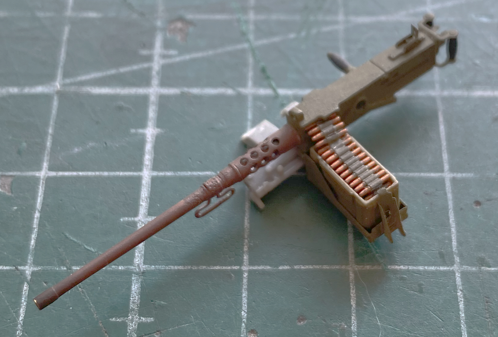
Who lets their weaponry get into such lousy condition?! Well, this maniac with the color-vision problem, is who. It’s rare that I’ll go back to a model once I’ve declared that it’s done, but this little abomination just had to be fixed. I decided to that I needed to fix that and, having forgotten to do it when I did the M24, now’s the time.
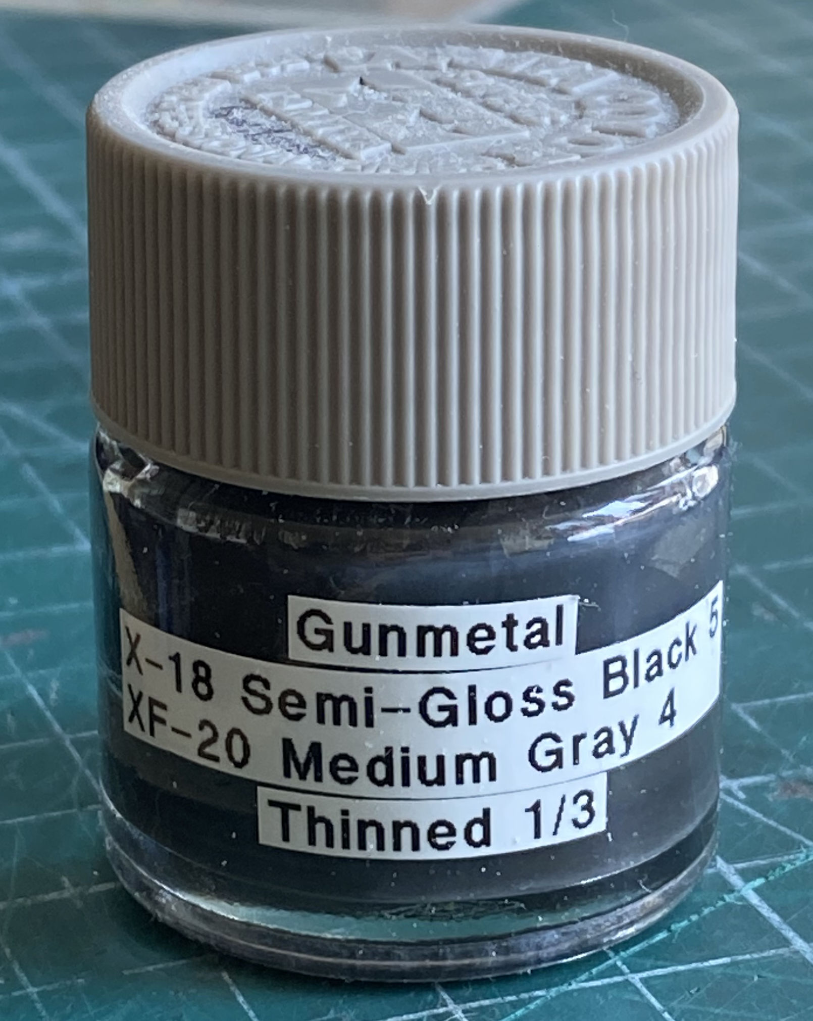
I’ve used a few different brands of gunmetal paint and liked none of them (unlike what I’d painted that gun with…). I brewed up my own:
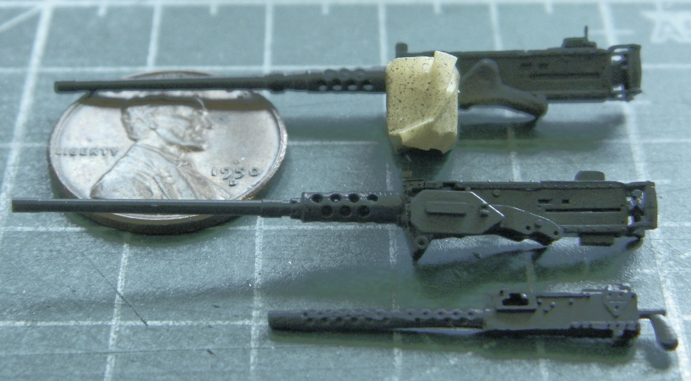
Much better:
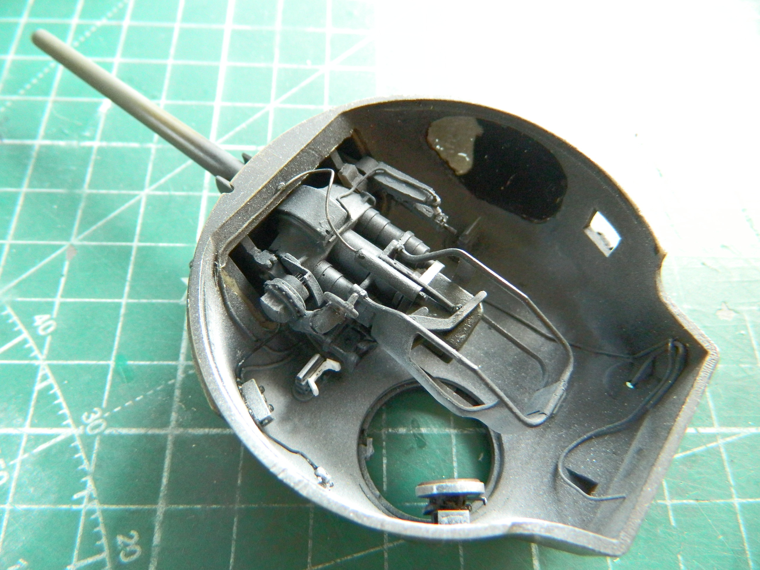
I added the light splash with Tamiya XF-2 Flat White to the major bits in the turret:


And then added the .30 cal (7.62mm) and the firing solenoid:

I dry-fit the 75mm and decided that I hadn’t added enough white:
More flat white got tossed and it looks better:


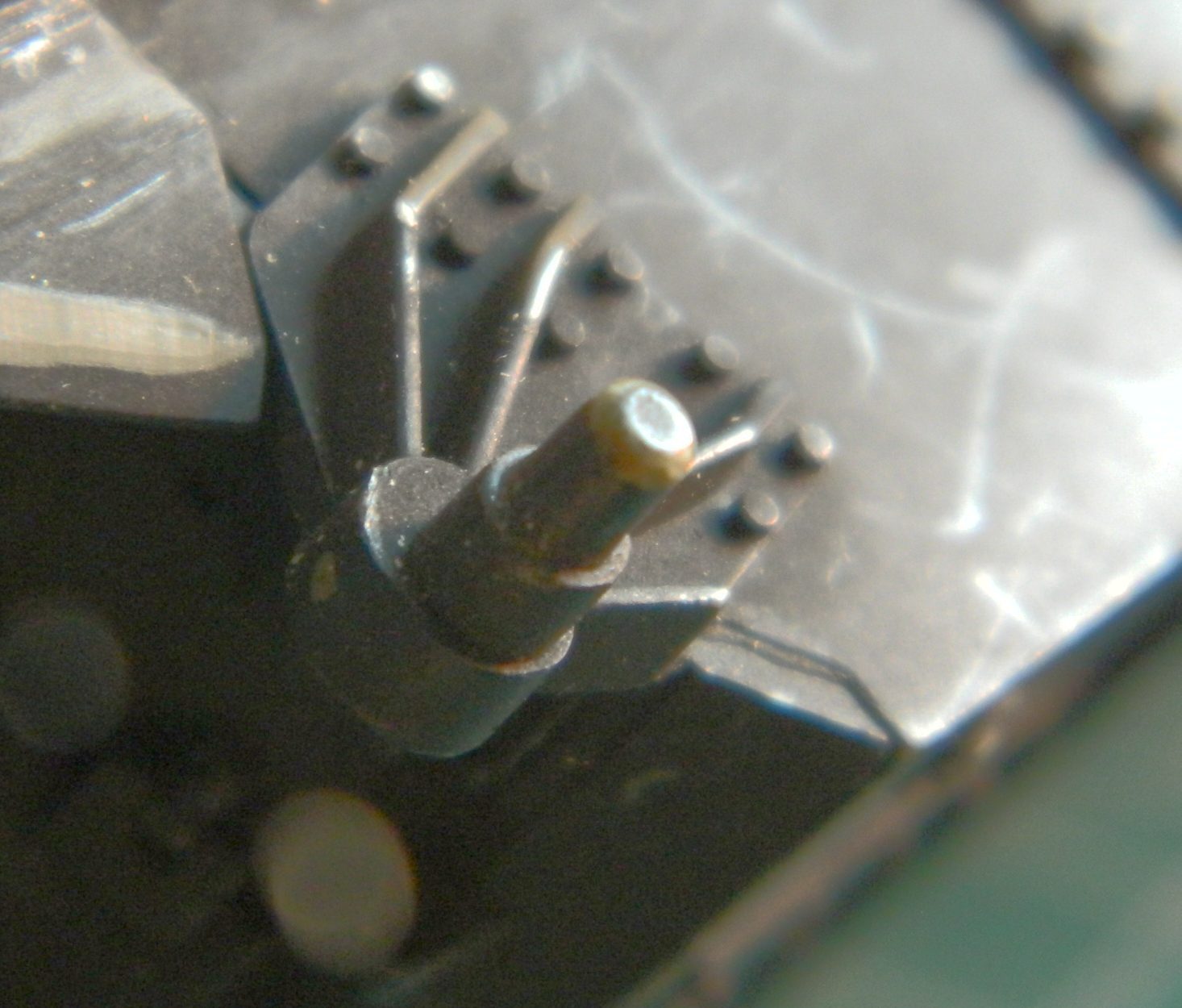
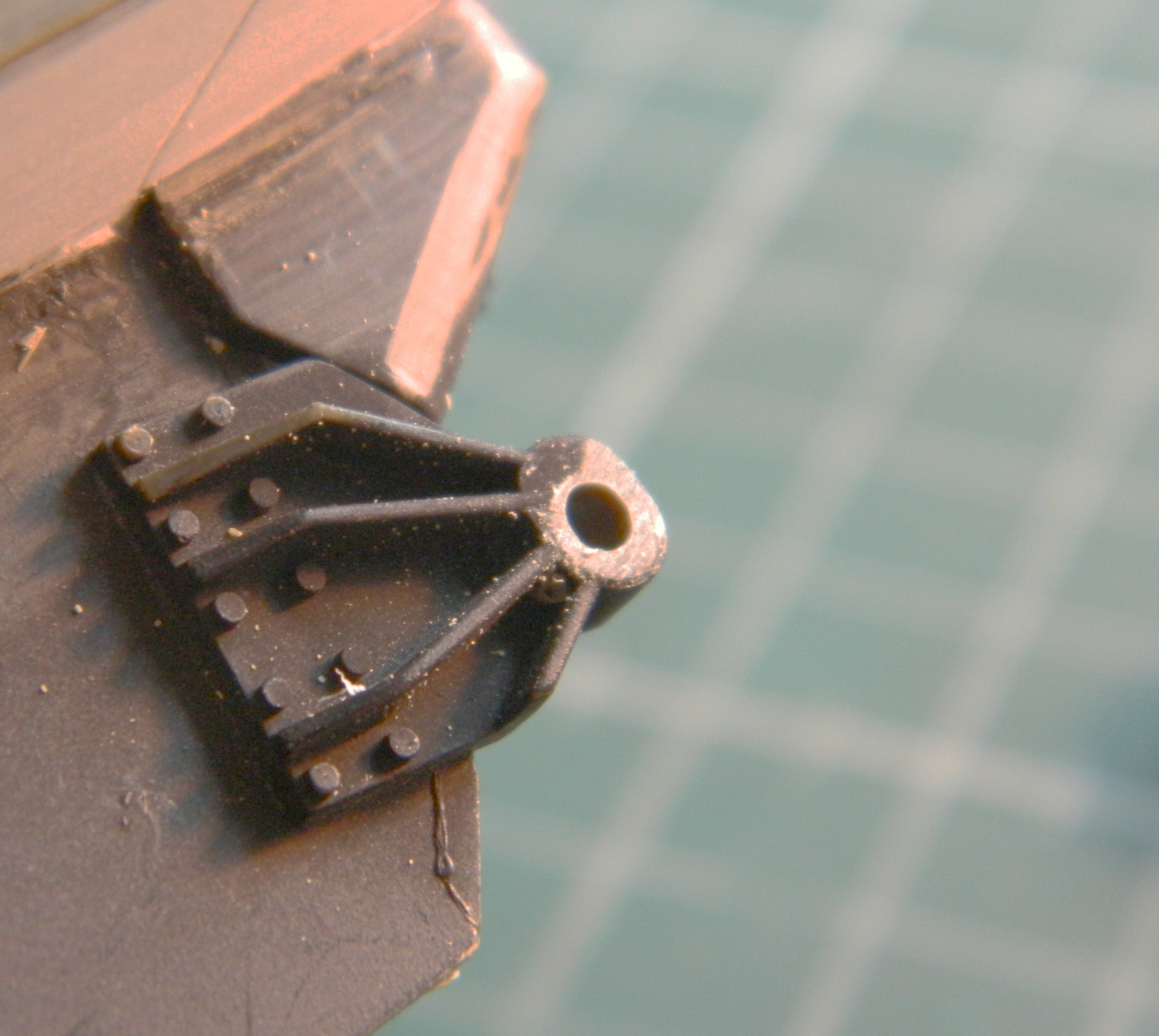
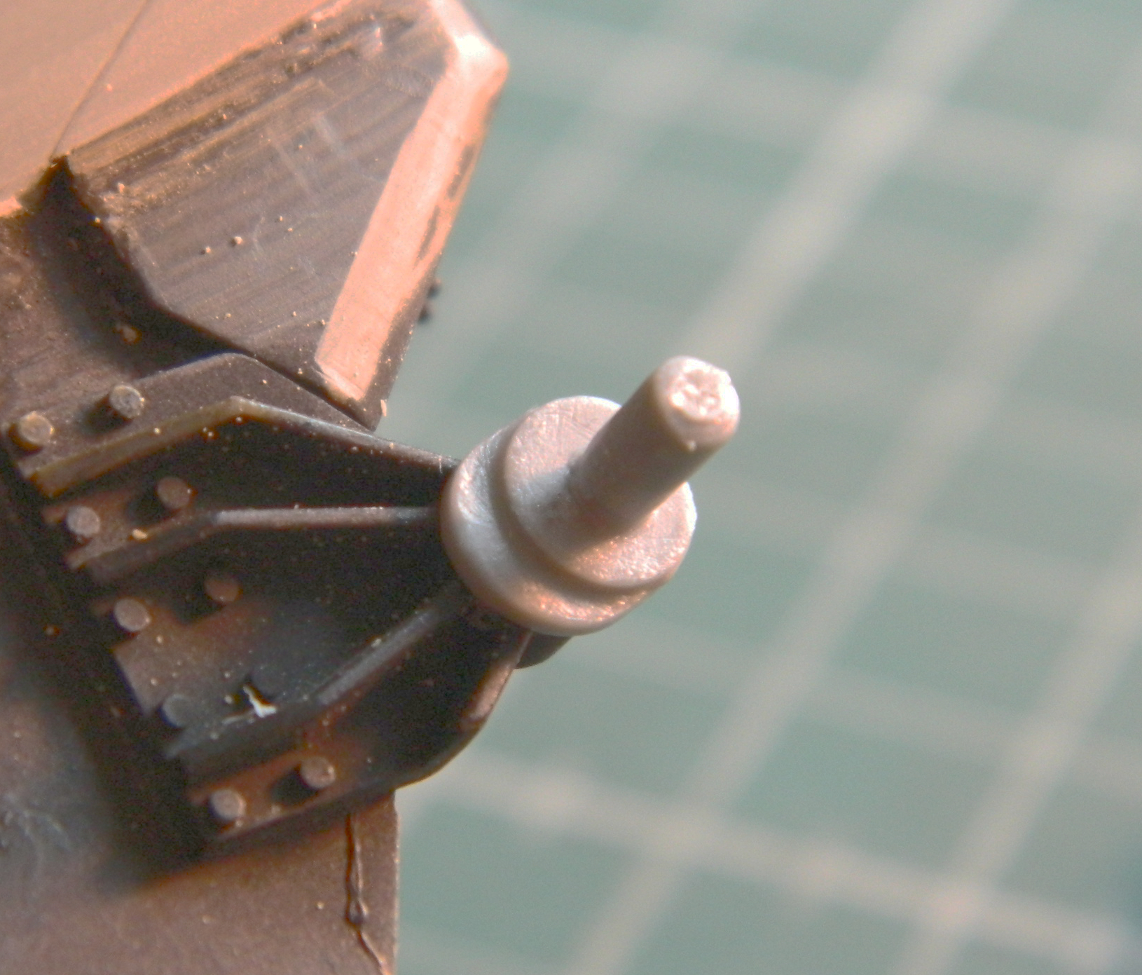
The junction boxes for the interphone weren’t supplied, so I made some using scrap .040″ (1.016mm) and .025″ (.635mm) rod. The styrene blocks were attached to a section of scrap cardboard with double-sided tape (because I really don’t like it when the tiny bits go skating around the bench). Jeweler’s tweezers are almost as good as having four hands:
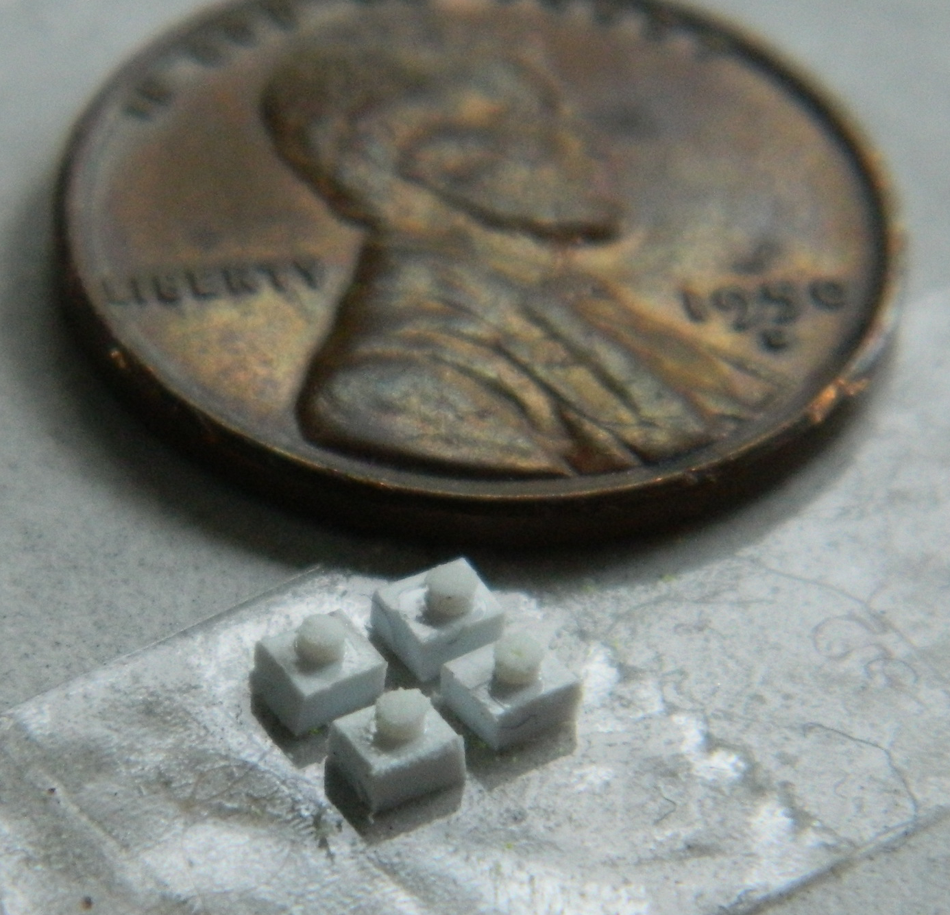
With the junction boxes built, holes for .010″ (.254mm) and .020″ (.504mm) solder “cables” were drilled and the boxes attached:
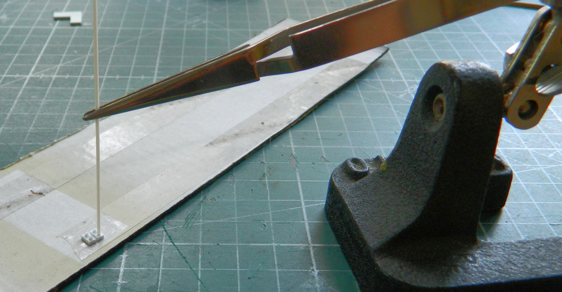
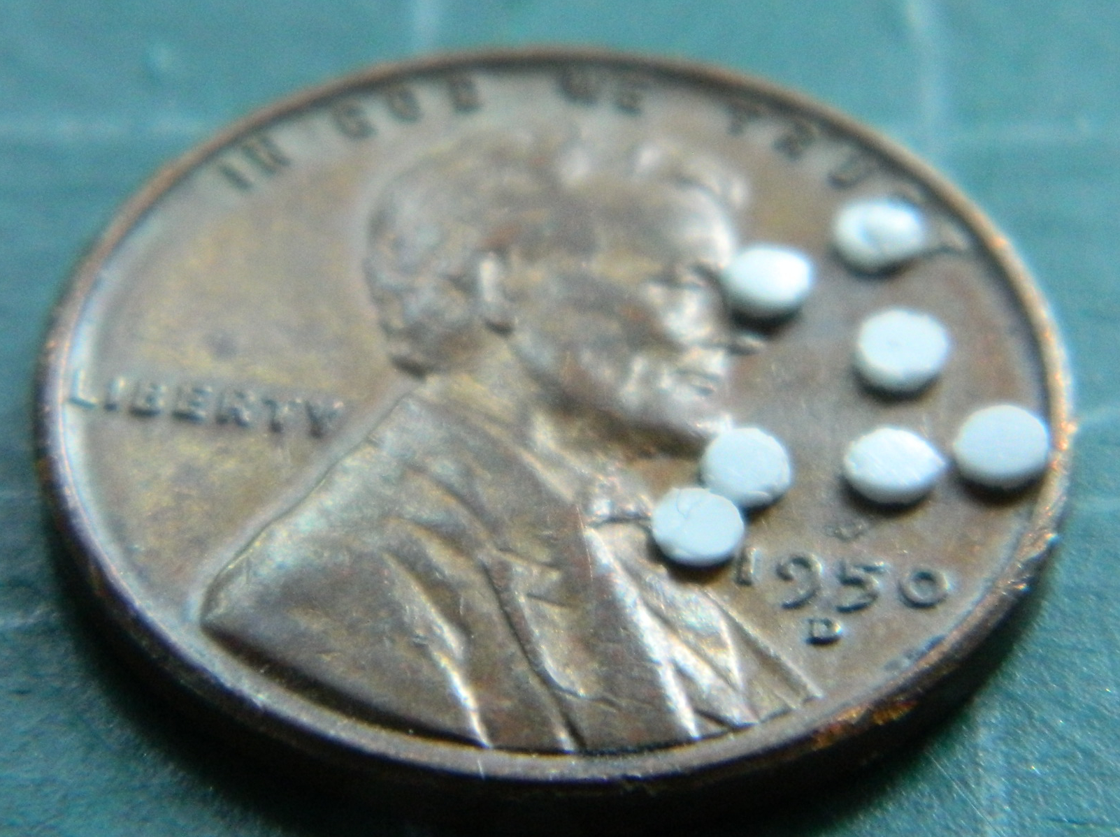
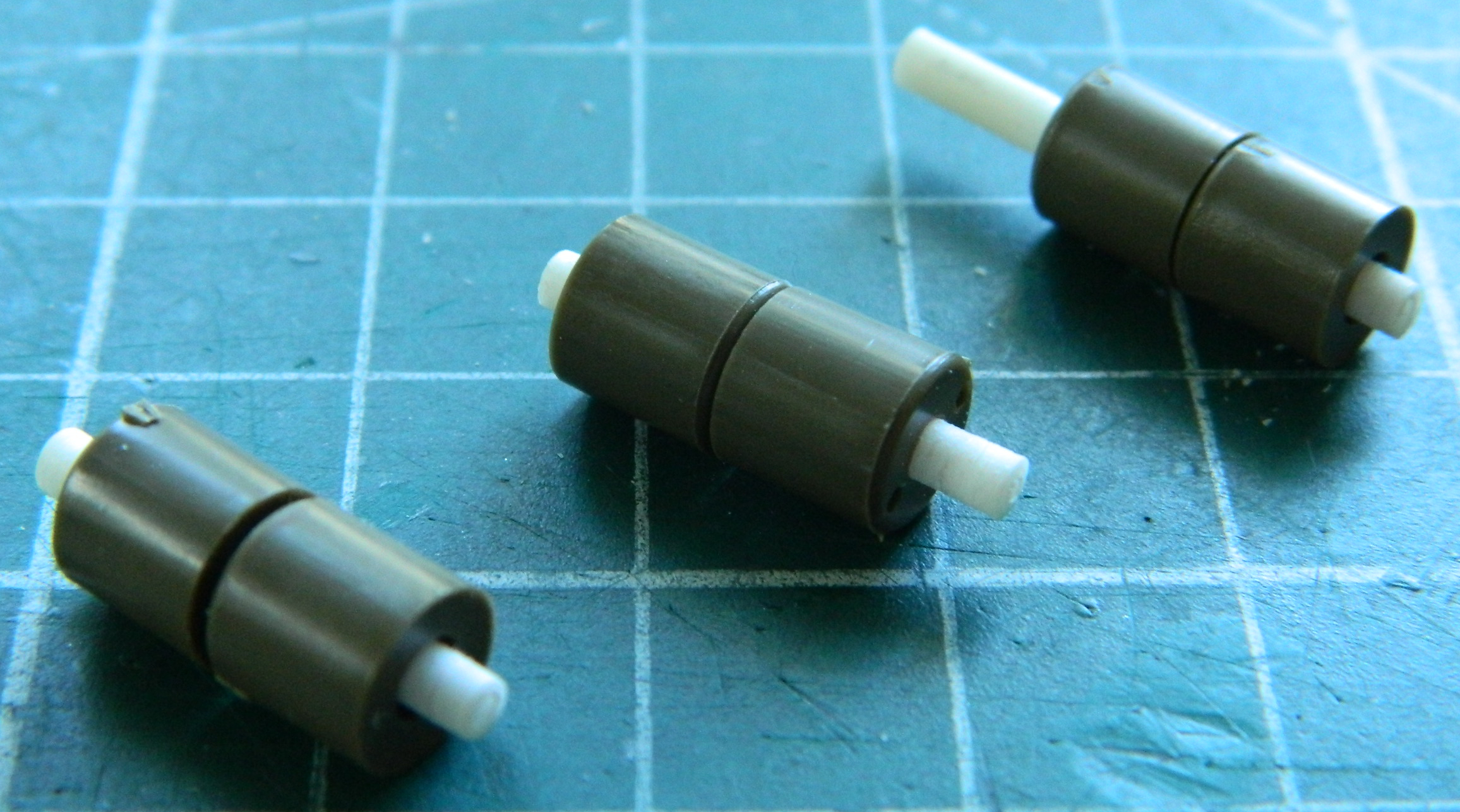
Next was to make the microphones. I knew that I was going to use only three (because the two by the driver and co-driver would never be seen) but I made five to be able to pick the best three. I started by punching discs for the mouthpiece from .015″ (.381mm) and (.635mm) rod for the handles and transducers. Once all the parts were ready, I used a bit of scrap .015″ (.381mm) to hold the handles parallel to the mouthpieces which were set onto double-sided tape to hold things while the bits were glued and the glue cured:

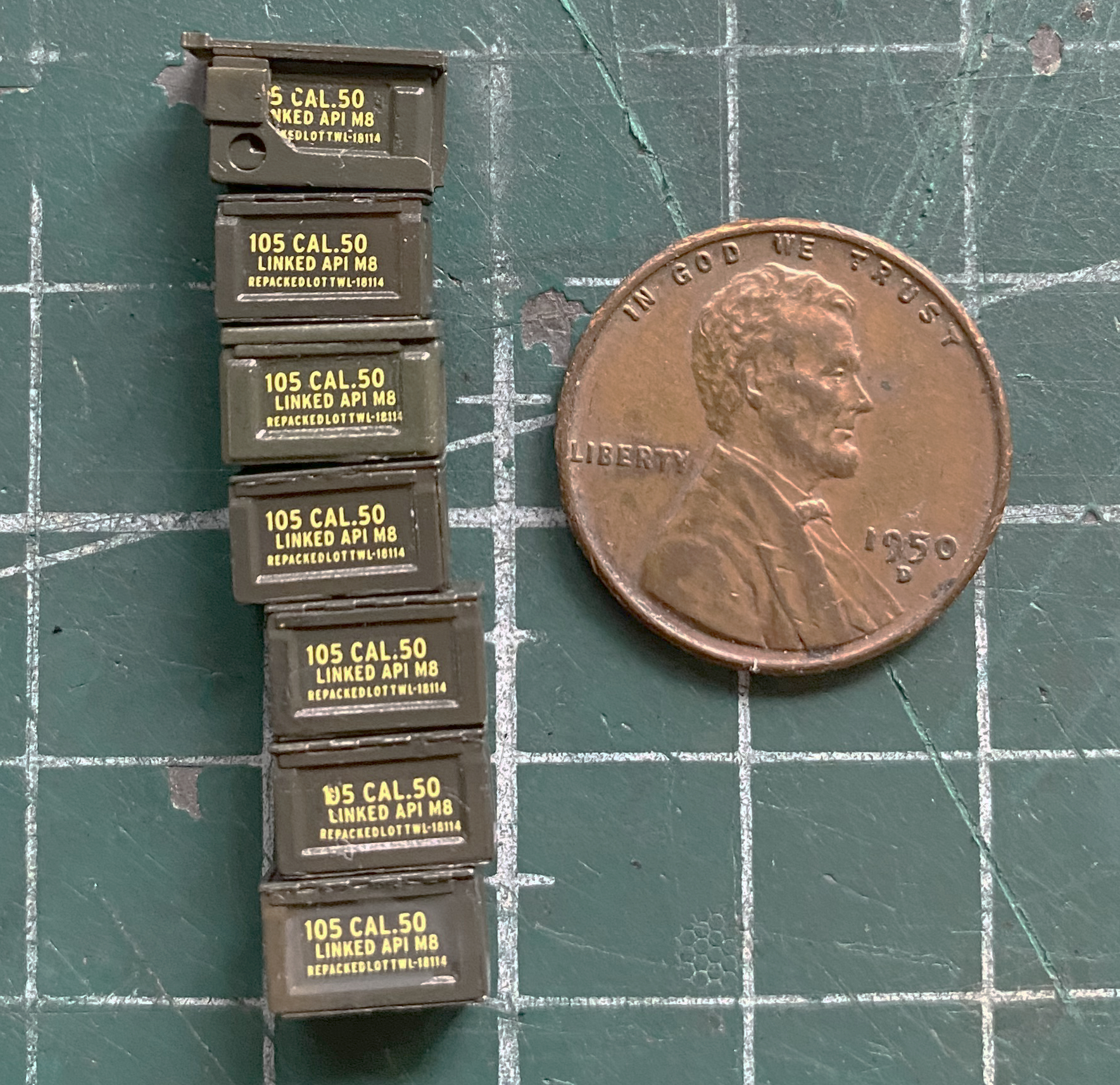
The “backstory: for this build is a tank fresh off an LST and being loaded for action (pre-Operation Cobra), which meant that I’d need several .50 caliber (1.27mm) ammunition cans. Once upon a time, Archer offered dry transfers and unfortunately the last factory that supplied the chemicals necessary to produce dry transfers shut its doors. Archer adapted and now offers very nicely done decals, in this specific case for the ammunition can labels:
Then I hit everything that I wanted to do a black wash on (which turned out to be utterly unnecessary) with clear gloss:

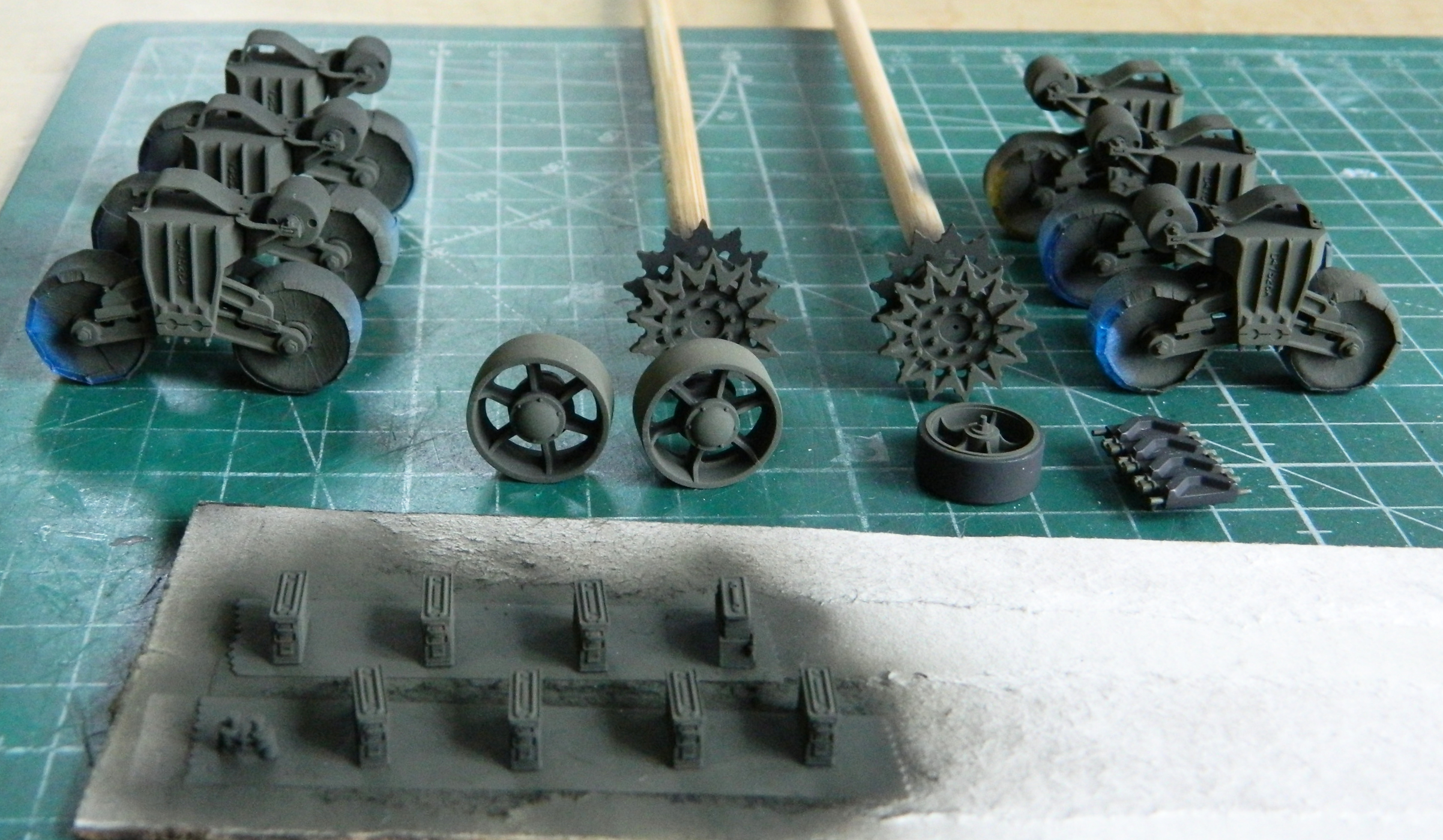
Having done an oil-based wash, I needed a few days for the oil paints to dry. While waiting, I set up the parts I’d need to do the road wheels and suspension and got them all cleaned up:
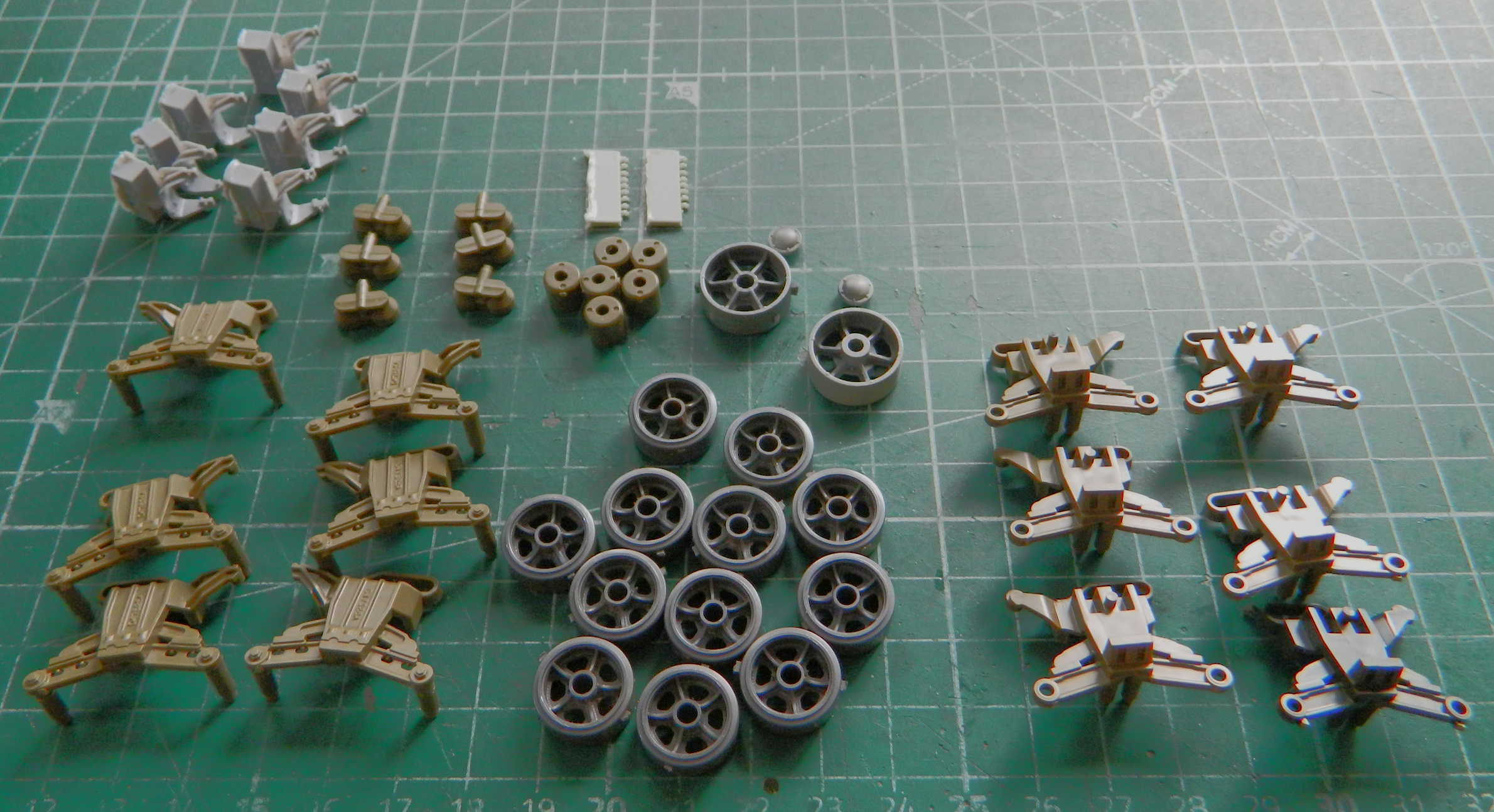
When that photo was taken, I’d planned on using a set of early road wheels from Dragon (spare parts inventory) because because their detail was a little bit crisper. The diameter of the center holes is larger enough than the Tamiya parts, whose bogeys I’ll be using, and I’d have to shim the center holes of the road wheels to get the correct fit. I took a close look at Tamiya’s road wheels and decided that the little bit of crispness that the Dragon part offered would be offset by the hassle getting them to fit would create. Instead I used the Tamiya road wheels.
This is the Tamiya bogey assembly:
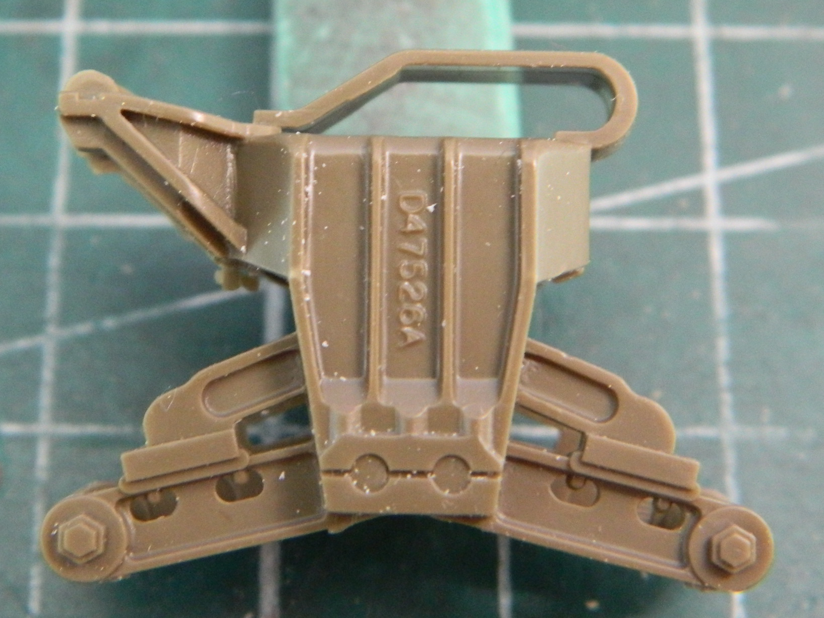
The roller return arm (top left on the outside of the bogey) is a later-production unit than I want to use on this earlier production tank. On top of the bogey is the track return skid. Not only is that a later production part as well, it’s quite out of scale. That means that both the roller return arm and the track return skid have to be removed and replaced. However, the mounting points for the return roller are on the arms. When they’re gone, so are the mounting points. That meant I had to come up with a shaft for the return rollers.
Checking my stock of styrene rod, I saw that one was too small and the other too large (and no Goldilocks rod to be had):
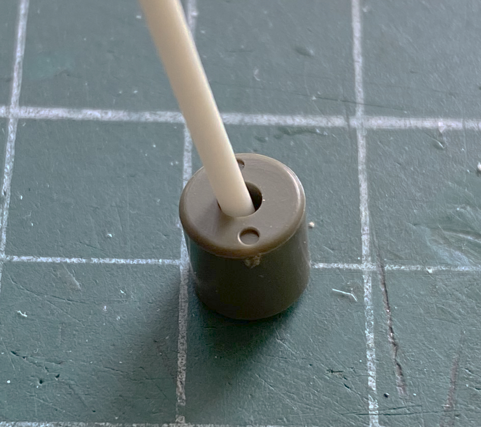

It’s easier to turn down something too large than it is to expand something that’s too small (or so she told me, anyway). I cut short sections of the larger rod and chucked them into my desktop lathe spun slowly and used a sanding stick (sourced from the nail supply section of the nearest drug store) (or apothecary if you live Over There) to reduce the diameters (I’m using the tip of my thumb…because my roommate wouldn’t cooperate…to hold the styrene rod against the sanding stick, otherwise it would flex too much and/or break off):
And that worked just fine:
Often when I’m at a build, I’ll prop myself up in the shop (it has the best light at this house) and sip my Elixir of Life (coffee, in case that’s not obvious). As my ability to focus, both my eyes and my brain, returns, I will frequently (okay, okay…sometimes) start to notice things that I hadn’t. This time it was how Tamiya molded the suspension arms where they attach to the bogeys. In the next photo, check how those arms attach to the bogey. The one on the left could move. The one on the right CANNOT move (look between the arms where they contact the bogey). I cut the plastic away from the unit on the left and then did all the other ones:

I flipped them over to make removing the errant plastic easier (the white plastic on the upper arms is where I’d nicked them while filing away the incorrect return roller arm):
Once the needless parts were filed off the bogeys, I ended with this:
Since the tedium was starting to annoy me, I switched tasks and painted the road wheels with Tamiya XF-85 Rubber Black and stuck them on skewers to dry:

After sitting overnight, I painted the steel hubs Tamiya XF-62 Olive Drab (3 parts) combined with Tamiya XF-2 Flat White (1 part). The easiest tool I’ve found for masking wheel hubs is an artist’s circle template (which I’ve used for aircraft wheel hubs, car wheel hubs):
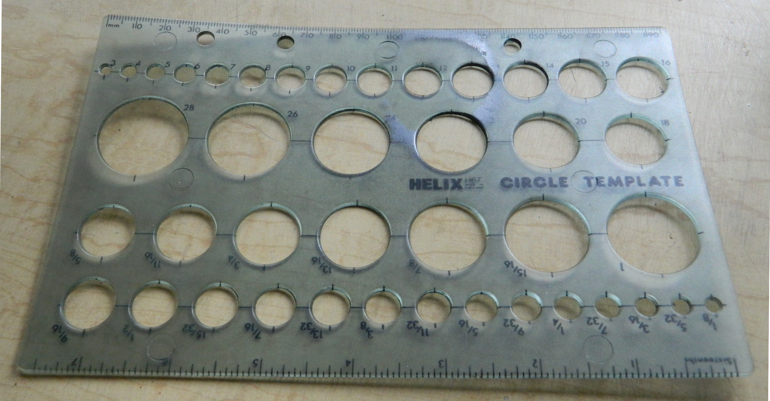
For these road wheels, the half inch (1.27mm) circle is about perfect. There’s sometimes a very minor bit of overspray around these wheels which perfectly mimics what can be seen on the real tanks. I held the wheel against the template with a fingertip from behind and got the wheel hub as centered as I can:
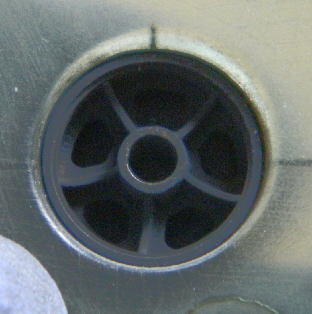
Having already painted the hubs’ lip with steel enamel, I used the edge of a toothpick to scrape away the OD and expose the steel where they’d rub against the track shoe locators (only half was done for the photo to offer a point of comparison)

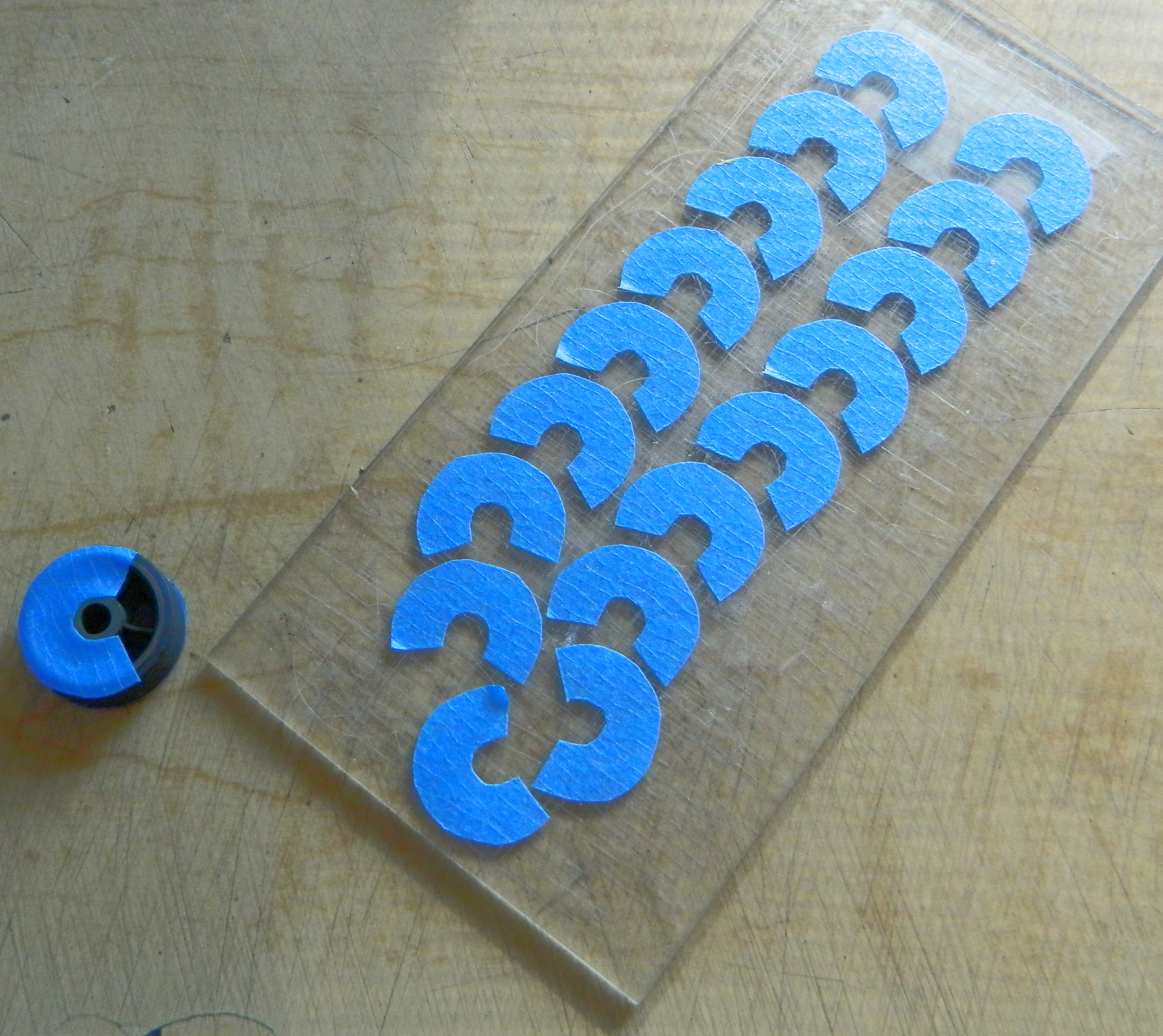
Once all the road wheels were painted, I masked them before attaching to make my life easier. Since the masks need to stay on until I’m done painting suspension parts, each section of mask is C-shaped so that they’re easily removable, and then a band of tape goes around the rubber rims:
Other things needed to be added to the bogey assemblies.
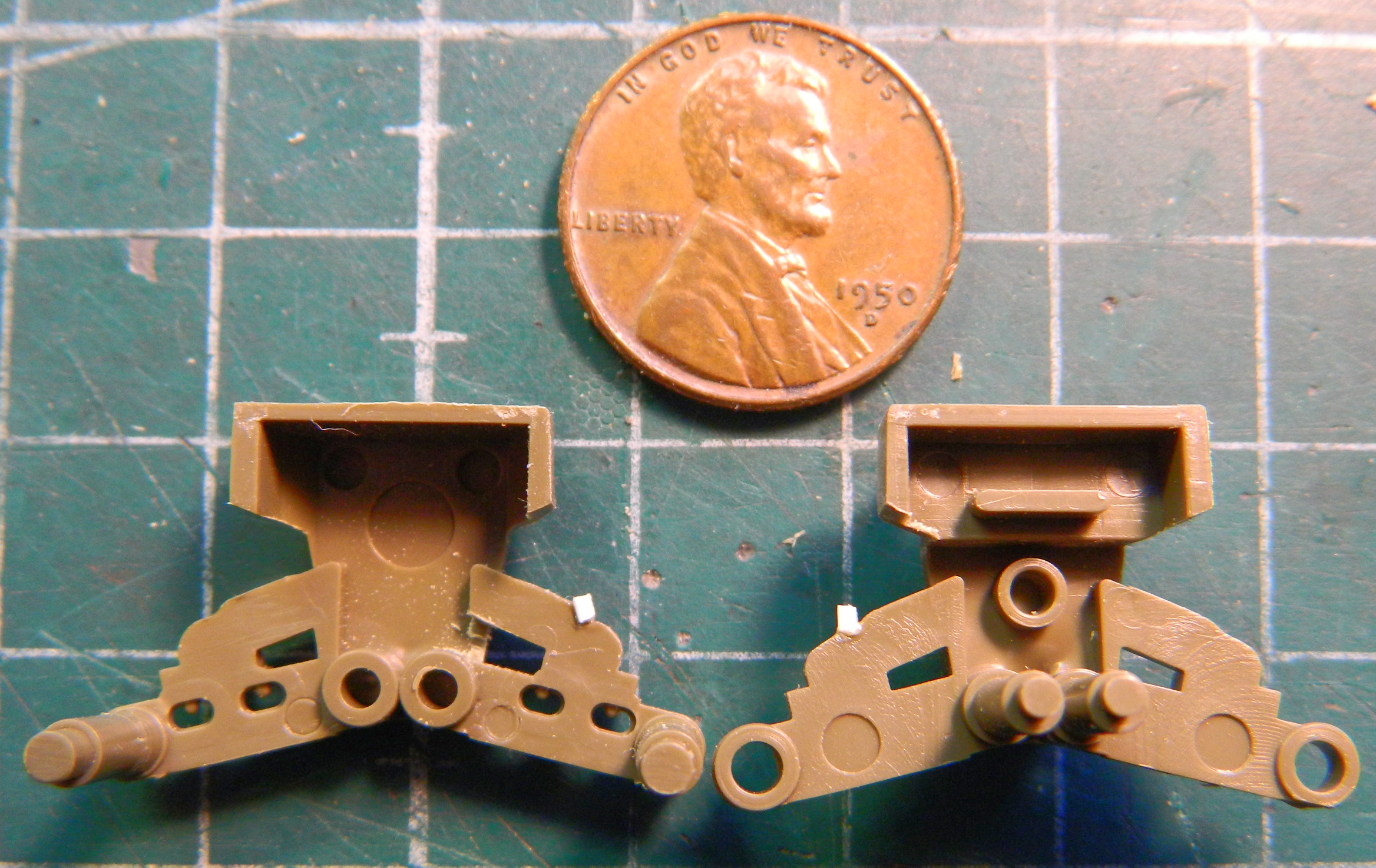
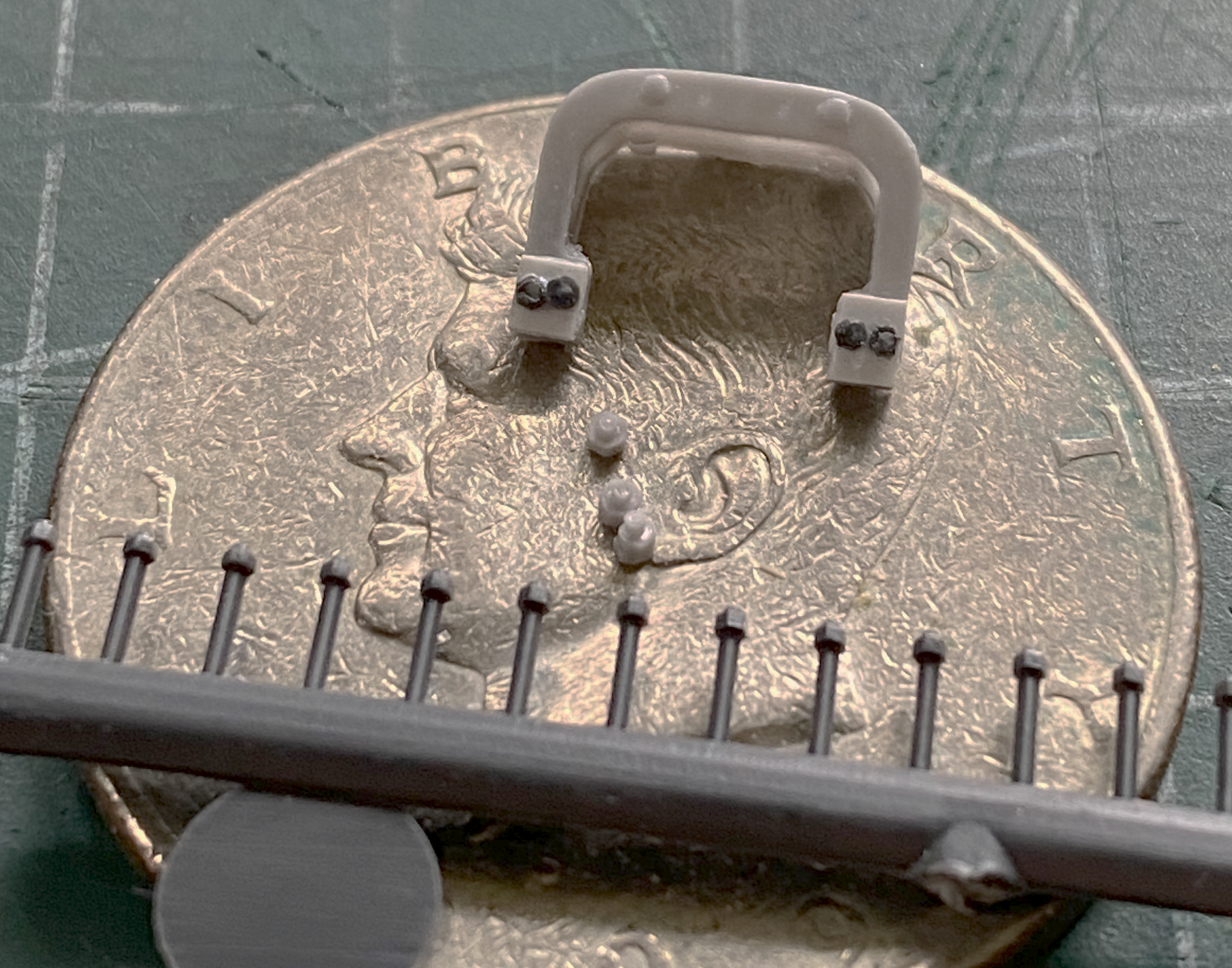
The return roller arm needed a little detail. Ordinance decided that the return roller needed to sit a couple of inches higher than the roller arm allowed. They inserted a steel “pillow” (their term, not mine) to raise the roller and bolted it to the arm. I used Tiger Model Design’s early arm, added the pillows using scrap styrene, and then used Grandt Line bolts to finish the part (I’m using a 50 cent piece as a scale indicator in the second photo because somehow I lost my penny…it’s in the shop somewhere):


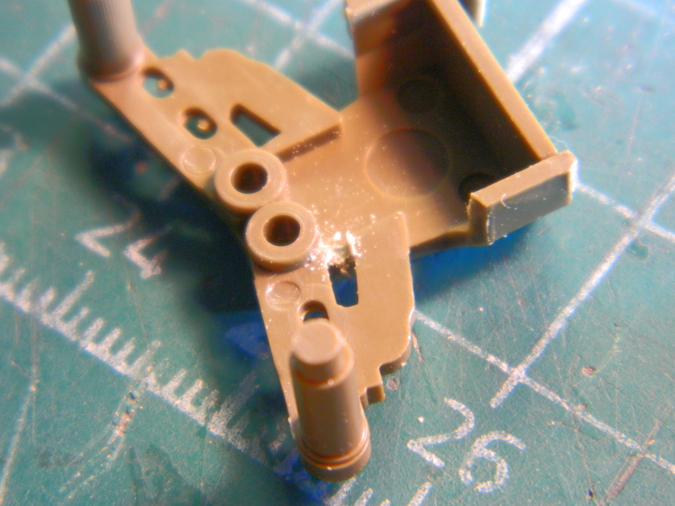
This is the mostly completed (more on that shortly) bogey assembly. The return skid has been replaced by Tiger Model Design’s (TMD) mid-production skid, the earlier straight return roller arm (also TMD), the return roller with its replacement axle, and if you look closely on top of the upper suspension arm, you’ll see the bolts that I added that should be there and were not. The bottom of the bogey has a cap held in place with three bolts to hold the trunion pins that were also not molded on. Once again, TMD had the parts and I added those as well:

There was one bogey casting used for either side of the tank. What determined which bogey went to which side was where things were bolted on. Making things SO much easier in the field to source parts from disabled/destroyed tanks was the bolt holes for the return roller arm were drilled and tapped into both sides of the bogey. I replicated those as well:
And now we get to the “mostly completed” part. I’d thought they were complete, needing only assembly after the first one shown above. And then I noticed this reference:
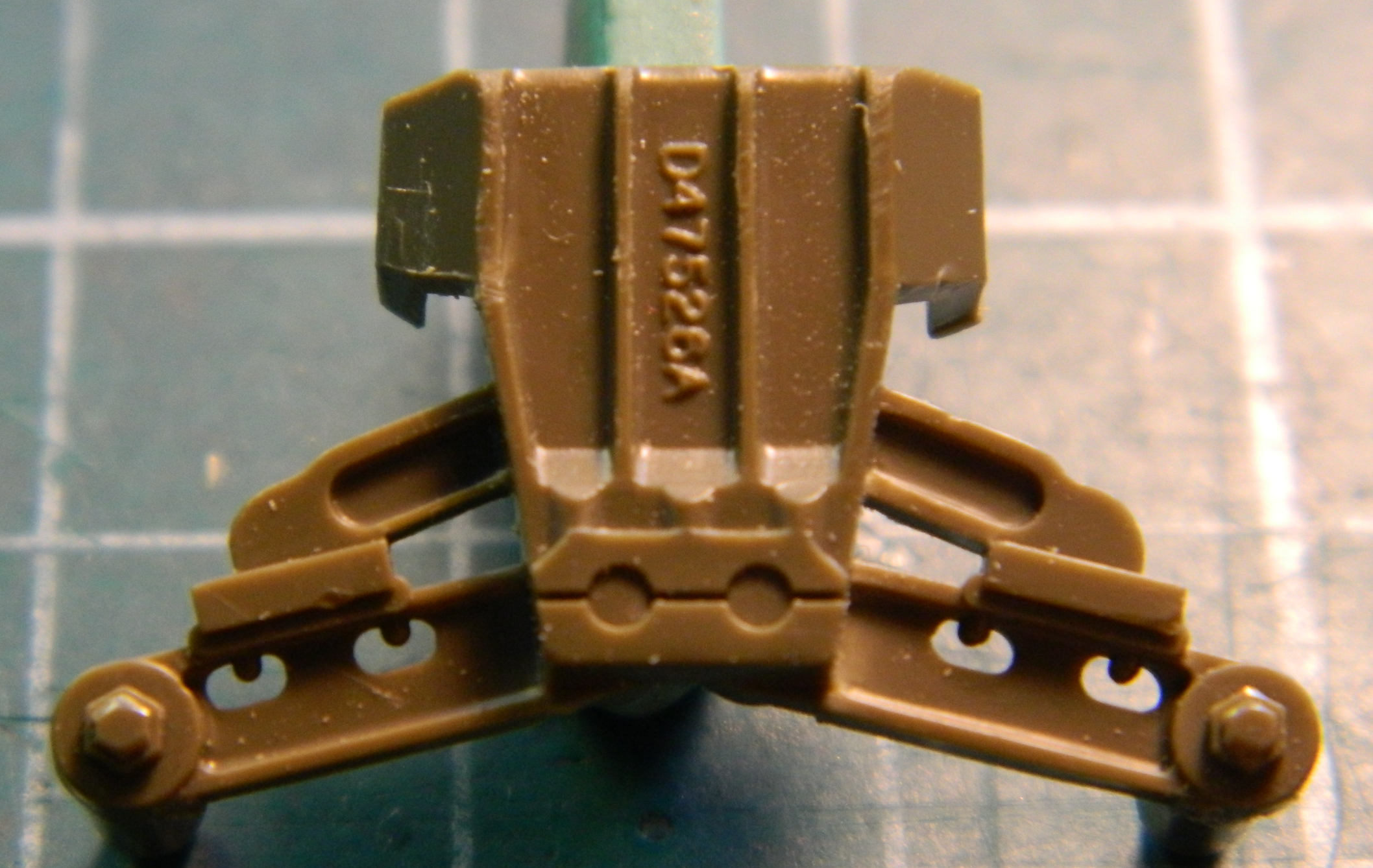
Where the upper suspension arm meets the lower suspension arm, the outside has a plate (to take most of the lateral forces that this assembly would experience I assume). The kit, however, has molded that as a block:

::sighs::
Okay, now that I’ve noticed it, I have to fix it. On the assembly pictured above, I had to be very careful with my excision, but I did manage it without damaging anything:

If I had to notice something like this, at least I noticed it before I had the other five bogeys assembled. It was much easier working with unassembled bogey halves and all were modified accordingly.
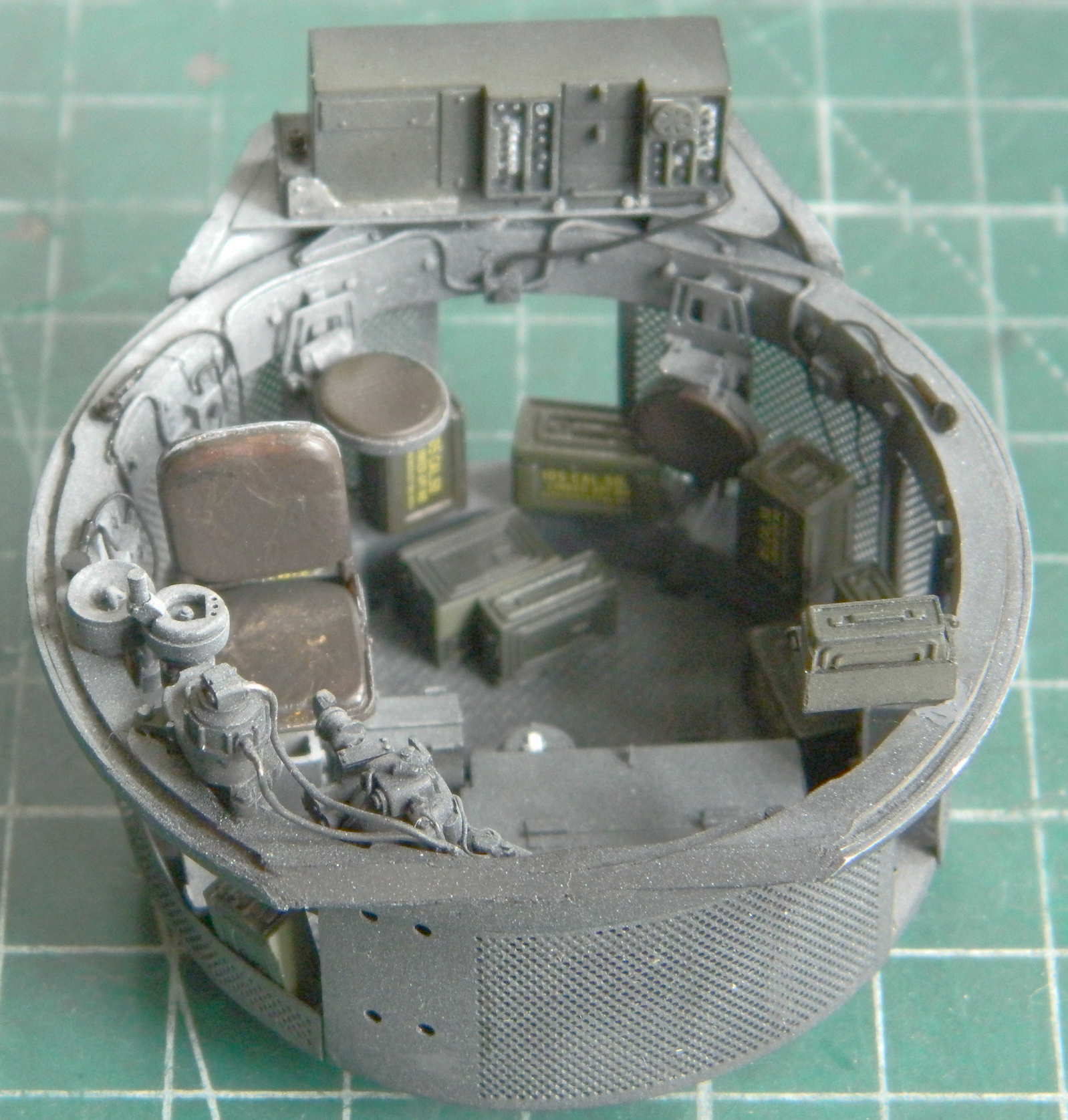
With all the bogey assemblies done, I turned back to the turret. I wanted to add ammunition cans stowed wherever they would fit. I dry-fit them so I could get some sense of what I would need shortly. The .50 caliber (1.27mm) are painted and the .30 caliber (7.62mm) are not and once I had their placements arranged, they were set aside to be painted:


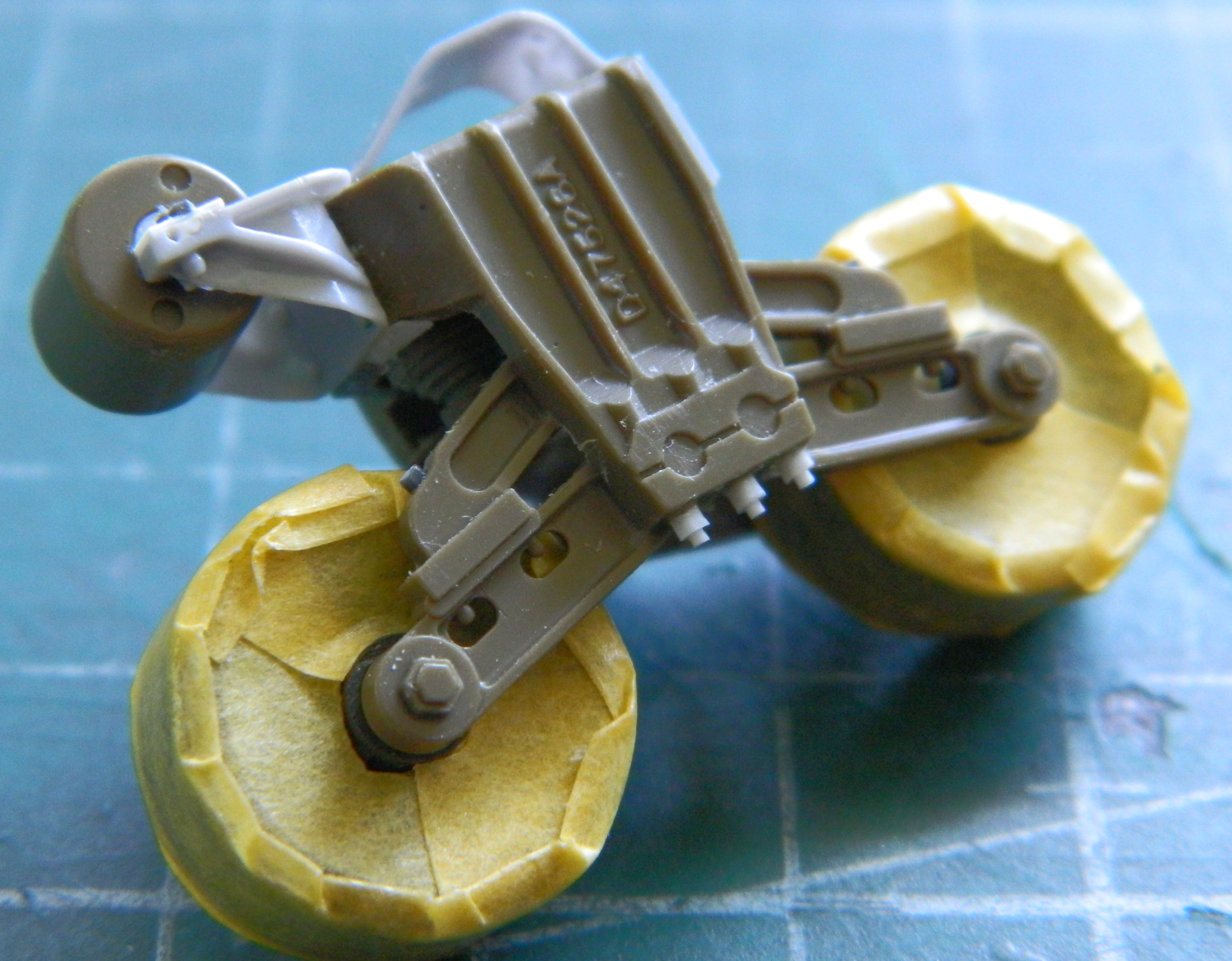
Tracks on the Sherman didn’t sag. Once again, TMD had very handy parts that would allow me to draw them tight once they were fitted. To enable their use, I had to remove the molded-on pin that the idler wheel attaches to:
Once removed, I drilled out the hole for the mounting pin on the eccentric mount:
Dry-fitting shows how much I can move the idler wheel and though it doesn’t move a lot, it moves enough to work:

I wanted to use the earlier style spoked wheel. It’s another Dragon part from my spares inventory and it’s shown below with the kit’s part for comparison:
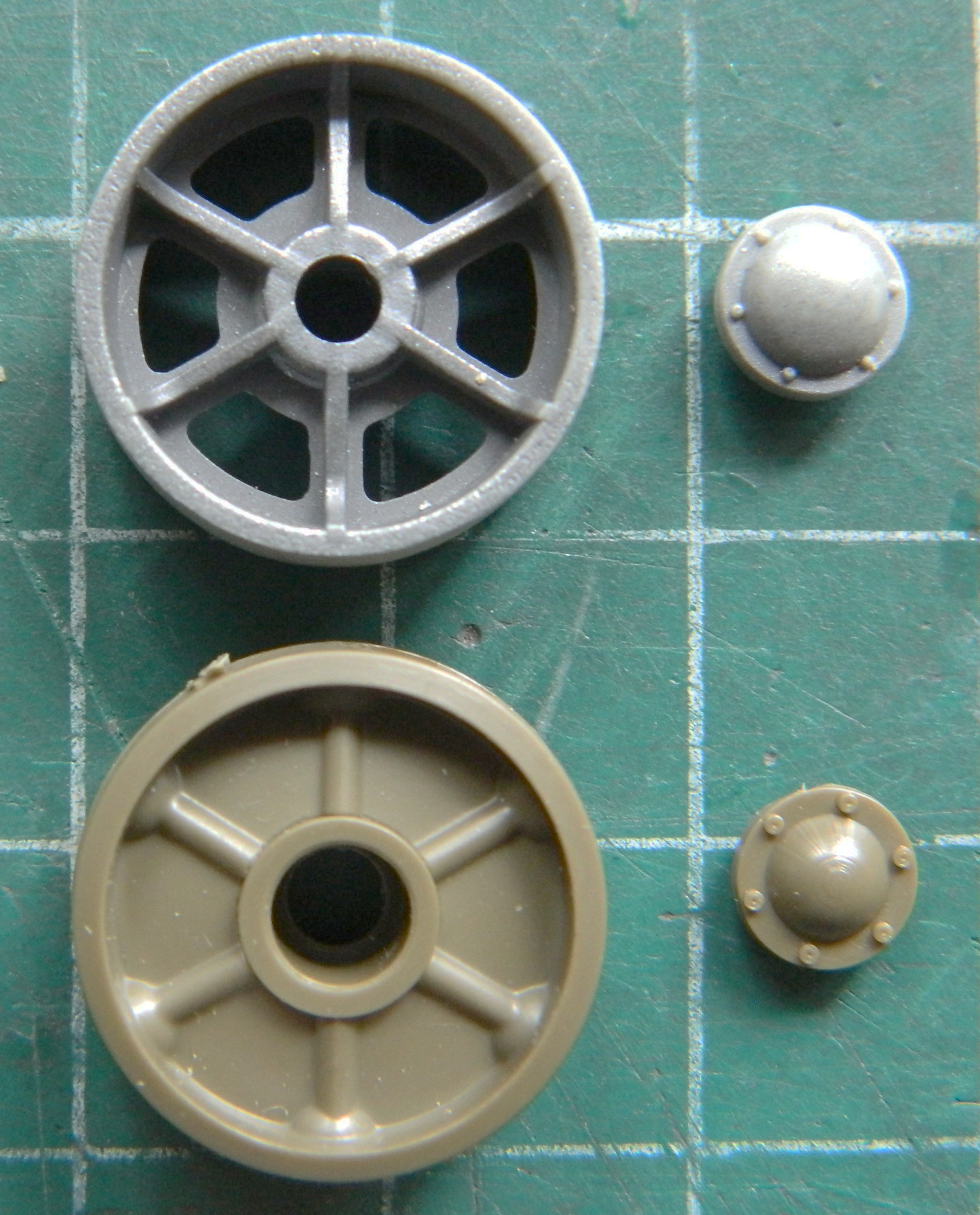
If you look for it, you can see that the pin that the idler is mounted on has a smaller diameter than the wheel’s hub:

Of course I thought of the most complicated and fiddly way to fix the fitment problem. Fill the hole and drill it out and hope that I get it correctly centered. Then my brain joined the fray and came up with something that would work well and be much easier to do without any reliance on hope. Since I don’t need the wheel to rotate, I centered the wheel on the pin and then filled the gap with superglue. Before the superglue set up, I added the hub cap:

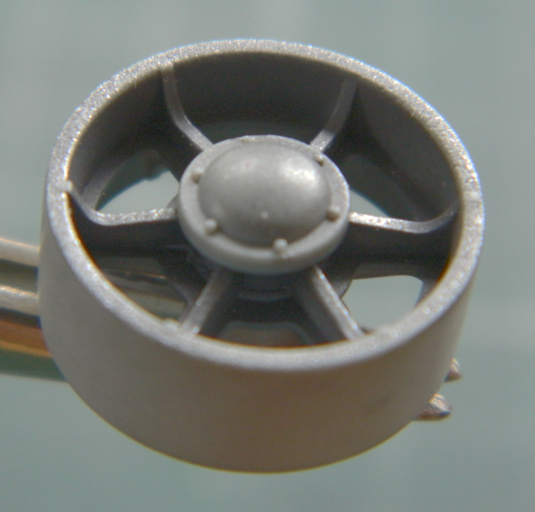
Much easier!
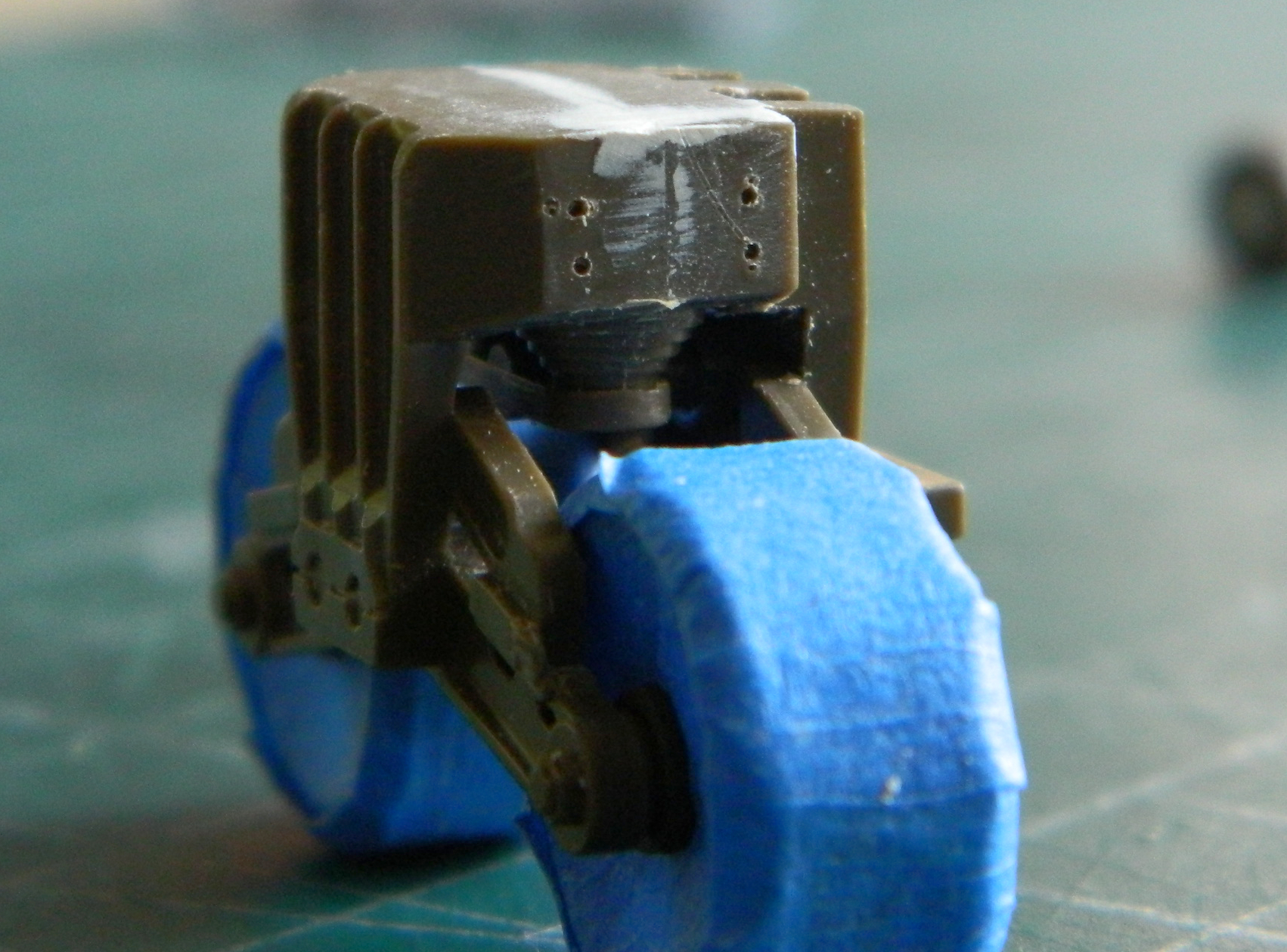
Another thing I quite dislike is trying to use opaque paint to replicate something clear. Again, it’s TMD to the rescue. They offer headlights of clear resin. I used a large needle to impress a socket on the back of the headlight and then applied a drop of black paint with the needle that created the depression. Then I coated the back of the headlights with a Molotow chrome marker and the result is what I was after:

Once all but the lens is painted OD, the result works nicely.
Then it was time to paint things. Most were done with color-corrected Tamiya XF-62 Olive Drab (3 parts) and XF-2 Flat White (1 part). And since I’ve decided to model a tank from the 3rd Armor Division, 32nd Armor Regiment, they mounted a spare road wheel on the upper left corner of the glacis plate and spare track centered on the front (some of their tanks didn’t have the added armor in front of the hatch hoods and had spare track mounted there as well, but since this build does have the added armor, only one run of track will be used) so those will be added. I shot the spare road wheel the same way I shot the road wheels with rubber rims and OD hubs using the template and I shot the spare tracks with rubber also, adding the OD to the track guides with a brush:
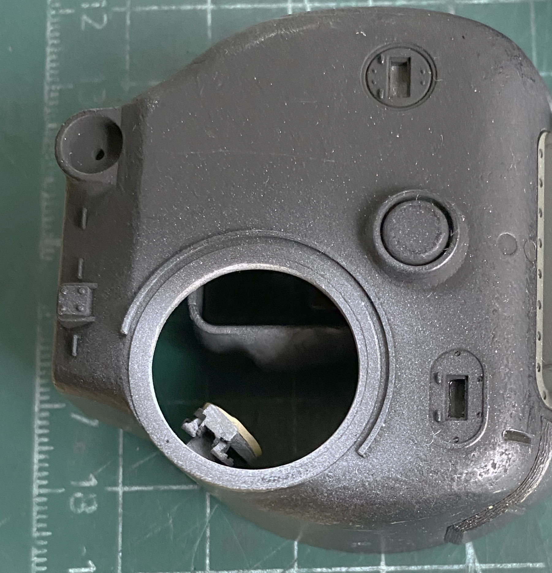
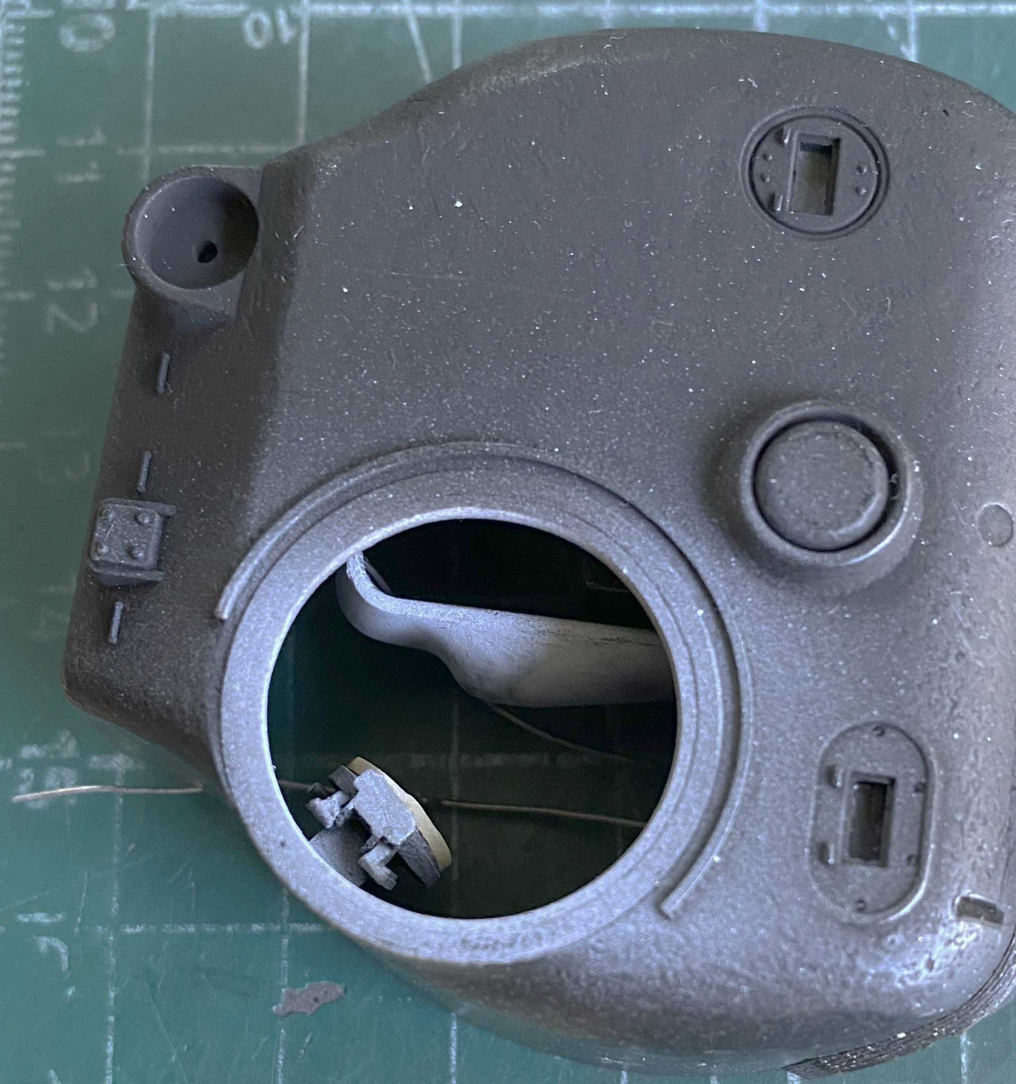
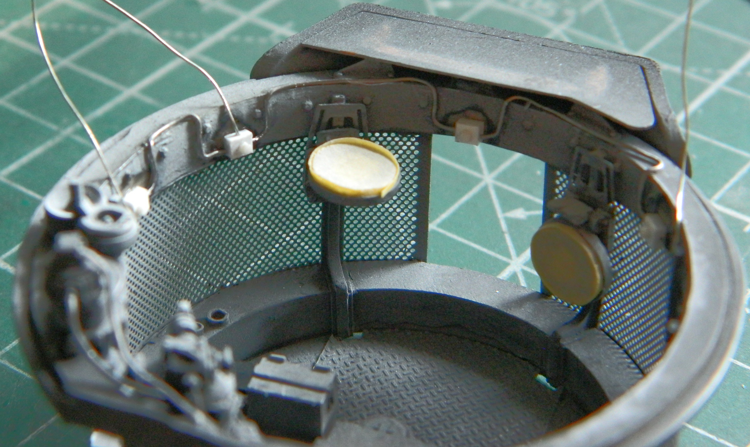
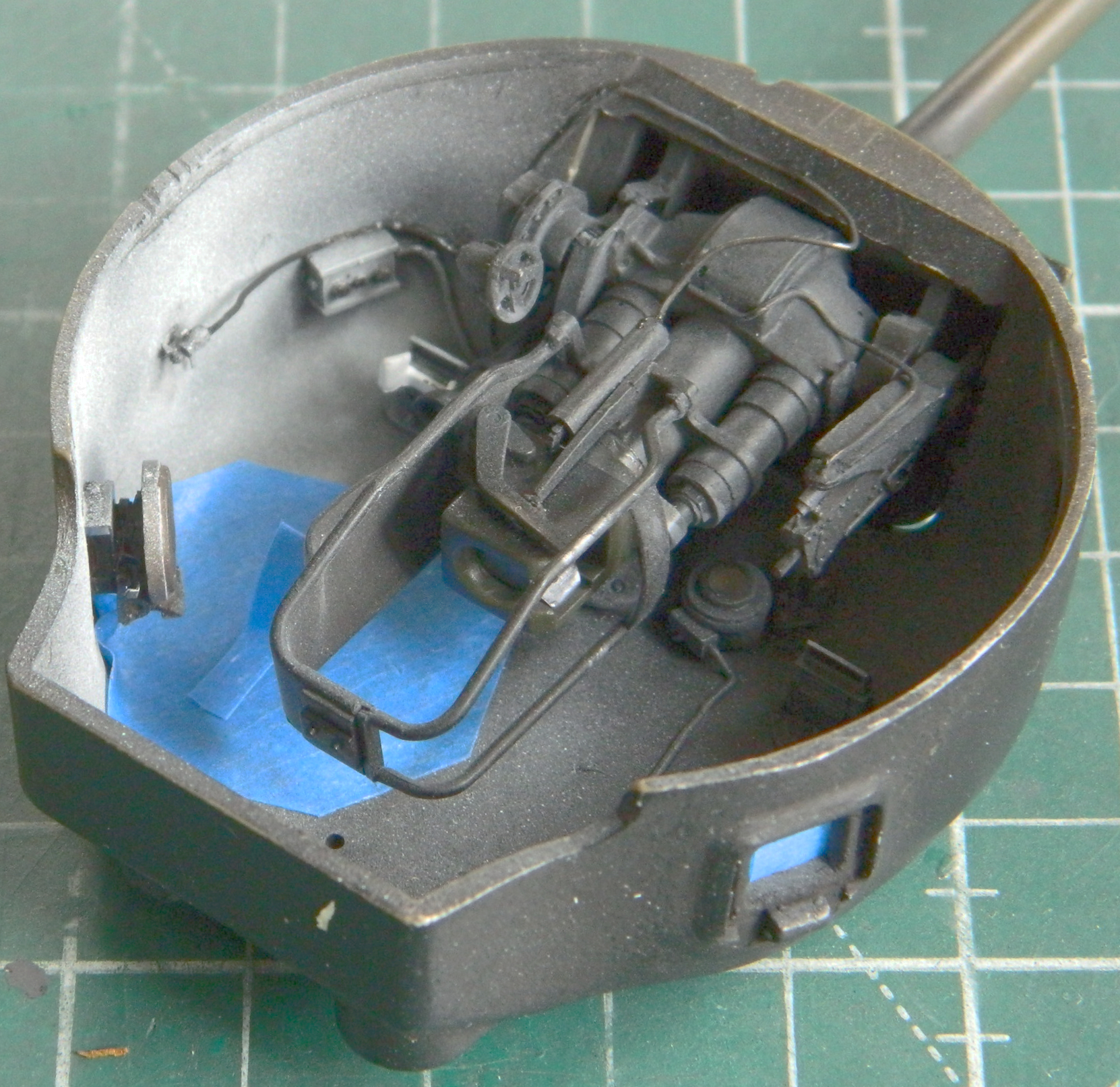
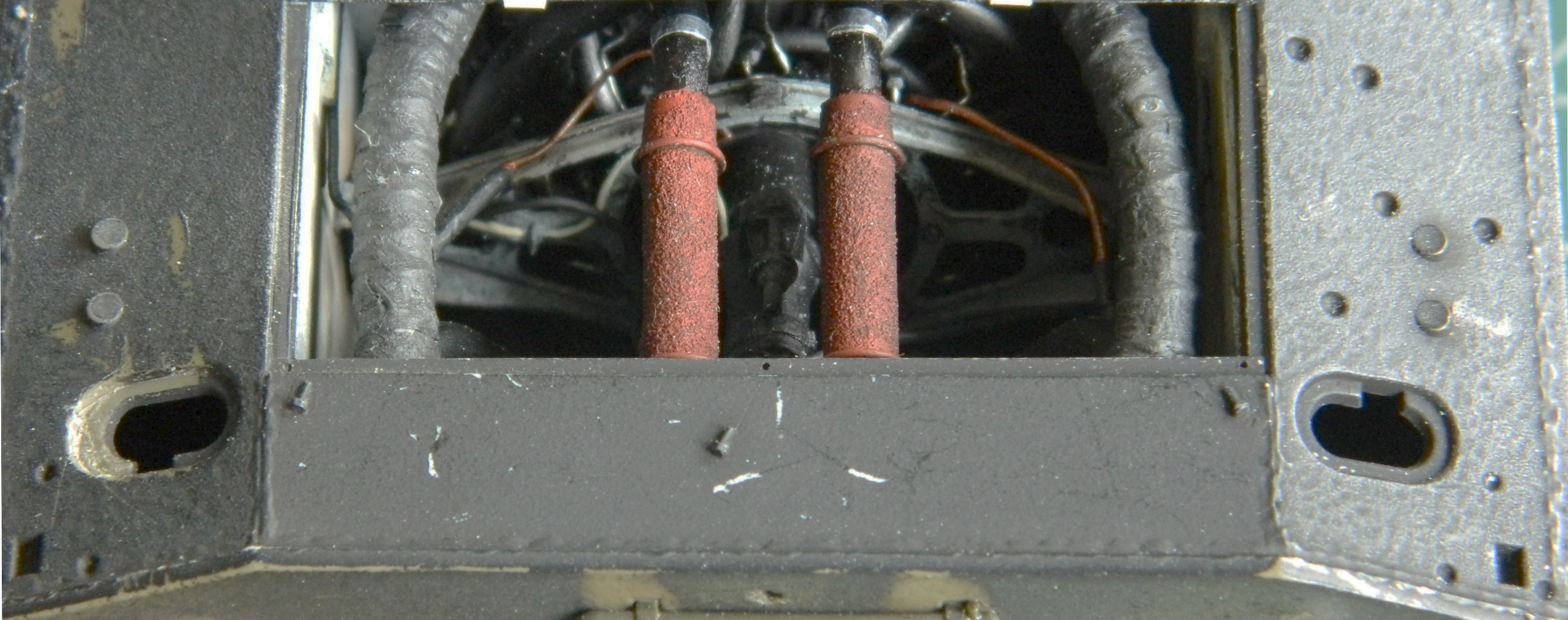
Time to close in on finishing the turret. The first step was getting the gun mounted permanently and attaching the various lines to and around it (I still have to trim back the end of the gunner’s optical sight). Prior to mounting the gun, I peeled off the masking tape from the inner surface of the clear panel and used a 50/50 mix of flat black and flat white to touch up the paint around the edge of the inner opening:

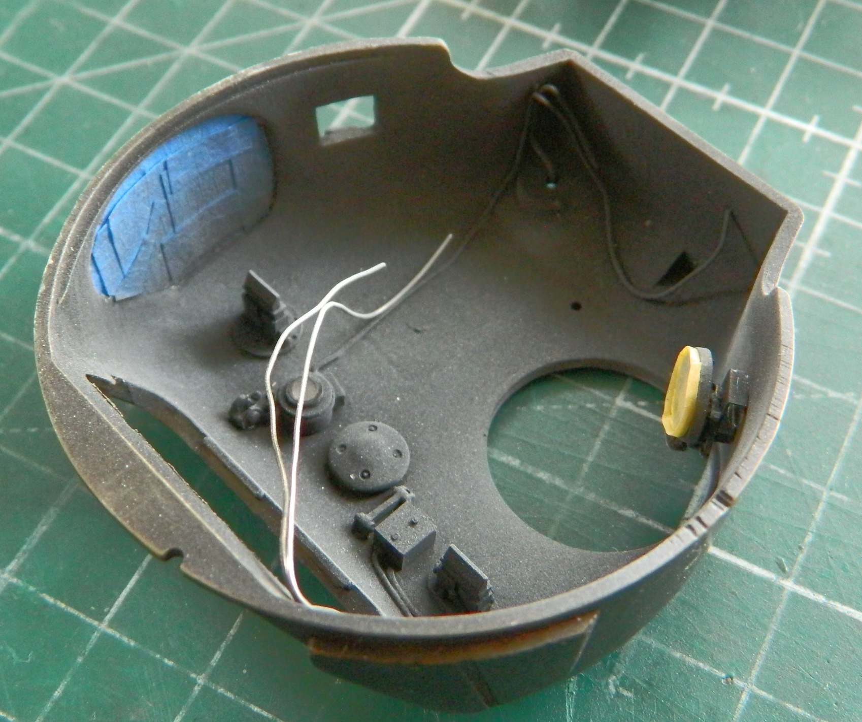
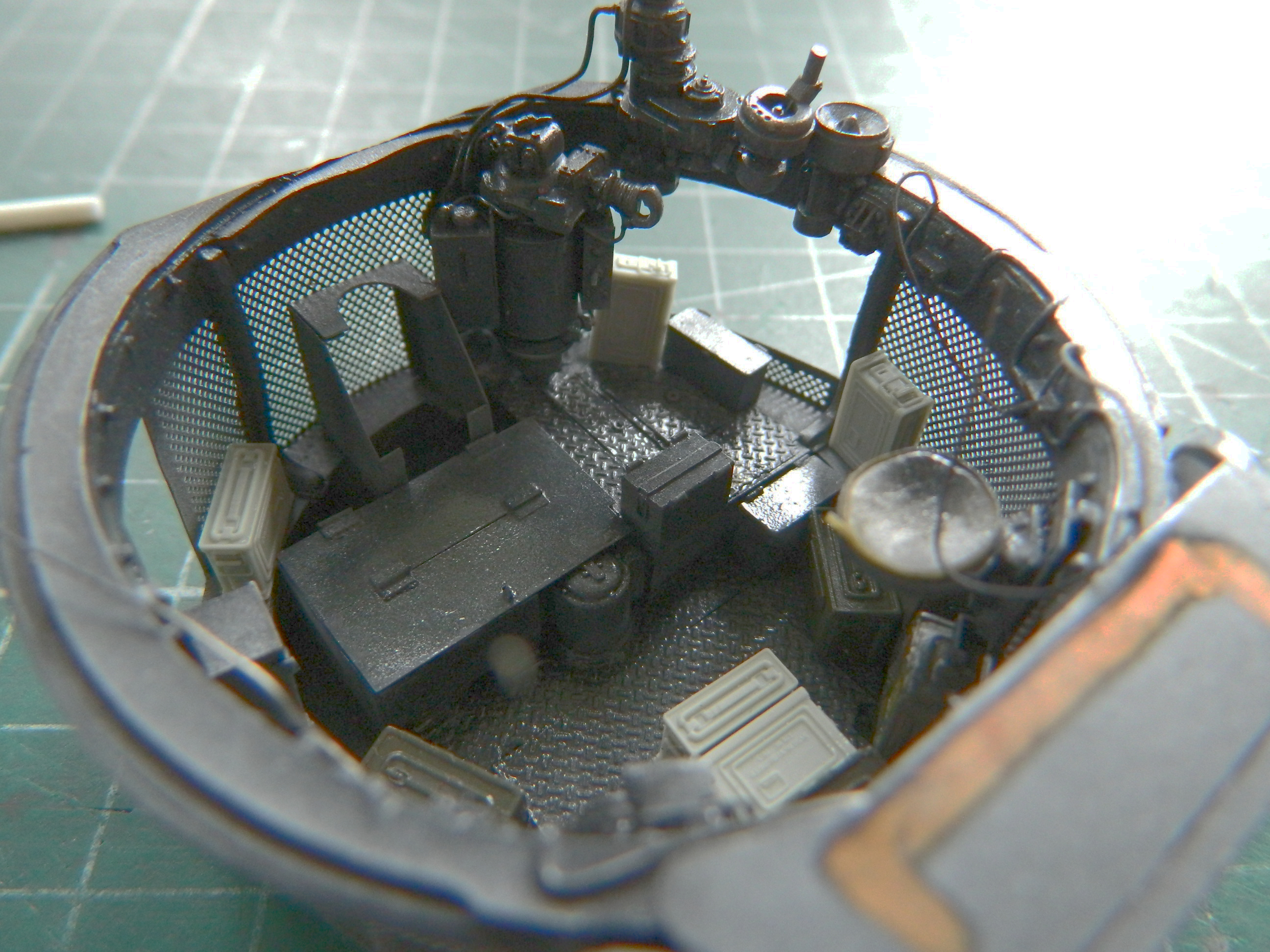
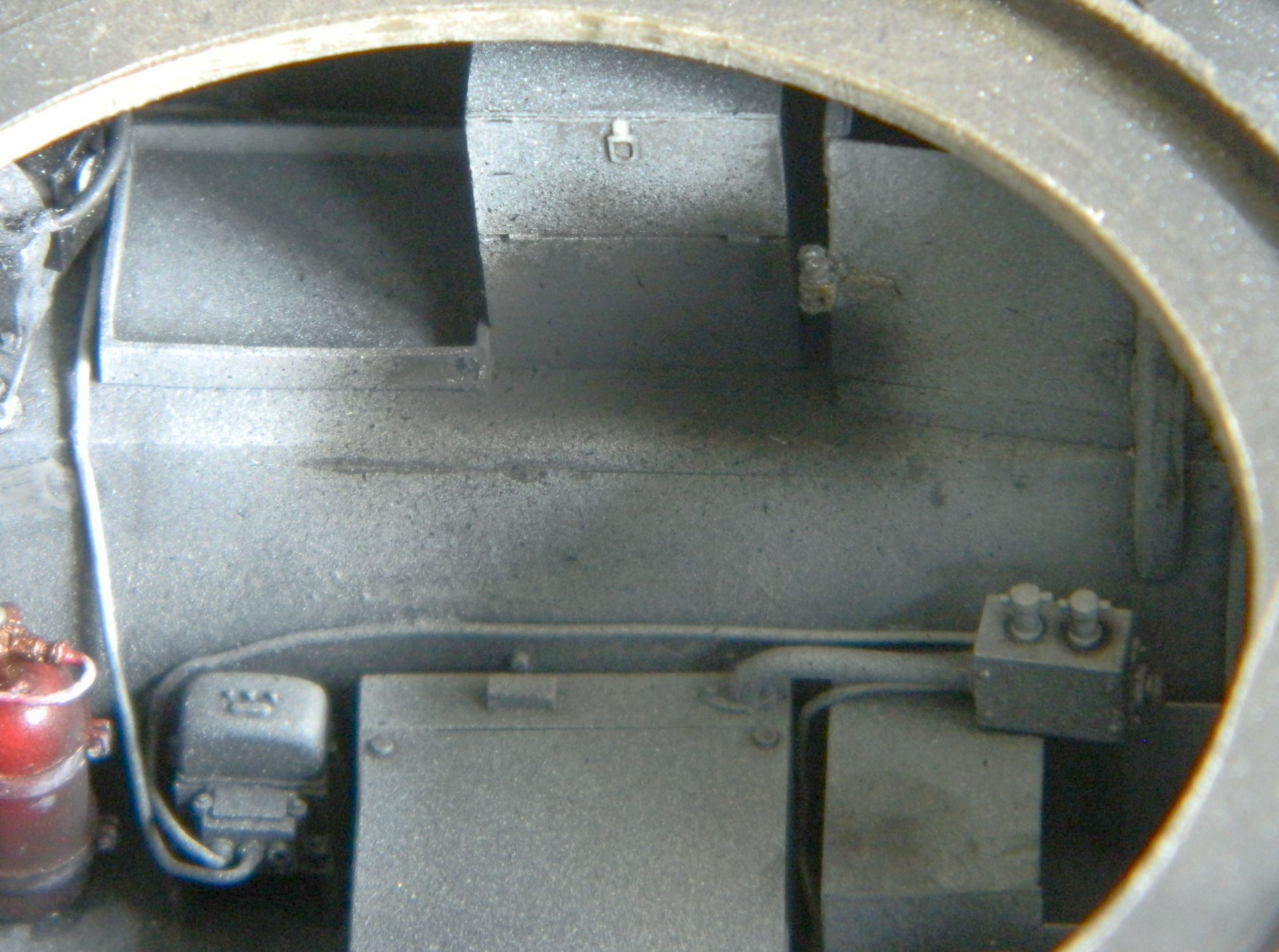
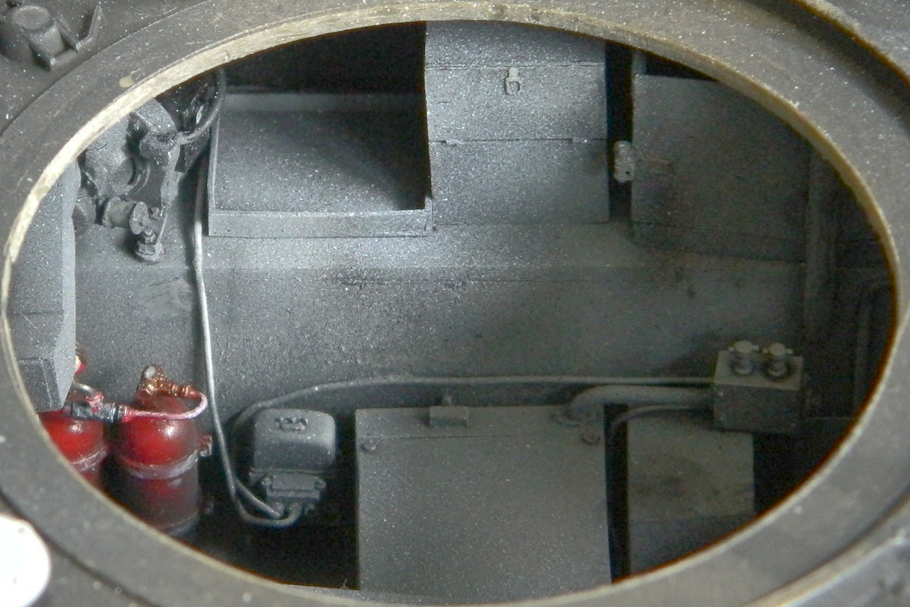
The final tasks with the turret basket were attended to. Errant lines were attached to their forever home, mics were painted and glued in place, the radio was glued down and various lines attached to it, masking peeled from the seats, and the ammunition cans were glued down using PVA:

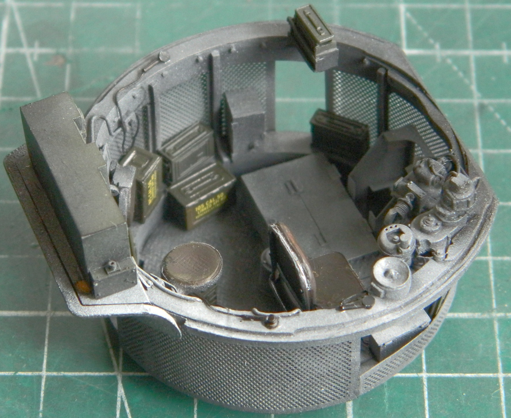
Before this is attached to the turret, there will be some staining with pastels. Since I’m modeling a tank more-or-less fresh off the LST, weathering and wear will be minimal.
When I was having fitment problems trying to get the turret basket to play nice with the interior of the hull, I had to move things in the hull to get that to happen. And since I’d already painted the interior, I had to touch up that paint. I put down flat black and then misted flat white light splash over it. I choked the airbrush spray pattern down about as far as I could and still allow the paint to spray:
I masked the hatch and gun port openings from the inside:
This tank will have the asymmetrical vents with PE screens (also supplied by TMD). These parts weren’t intended for the Tamiya kit and as such were just a little bit wider than the depressions molded into the kit. I widened the depressions (the left side is done, the right left alone for the photo comparison):
Keeping with my process of realizing too late that something needed to be painted before installation, I didn’t paint the inside of the vents before adding the PE grills and gluing them down. Rather than try to pry those out and then have to fix the gouges, I’ll go with painting them flat black later, since the that’s what I’ll be painting the outside with anyway:

Next time I’ll be working the hull exterior.
