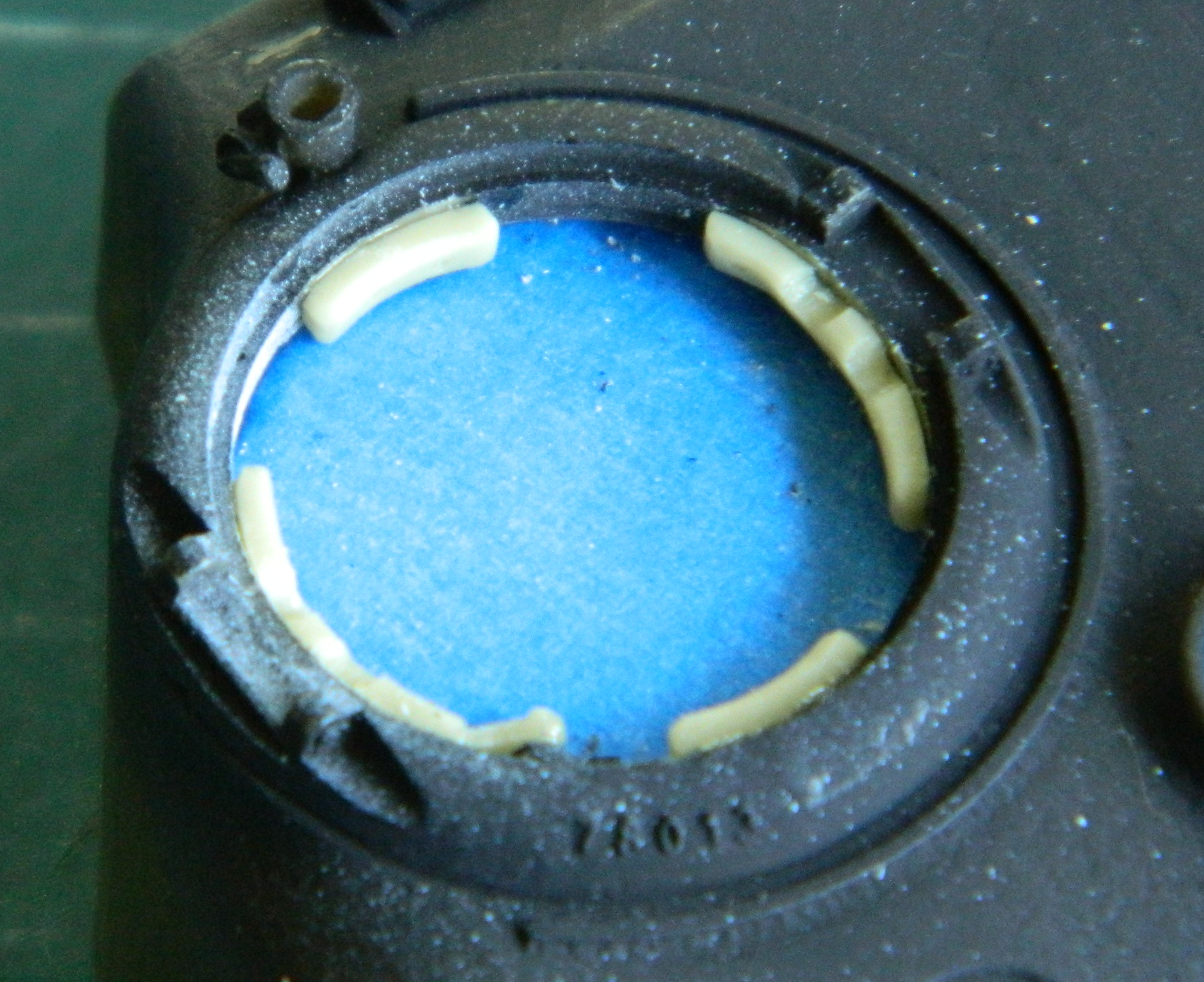
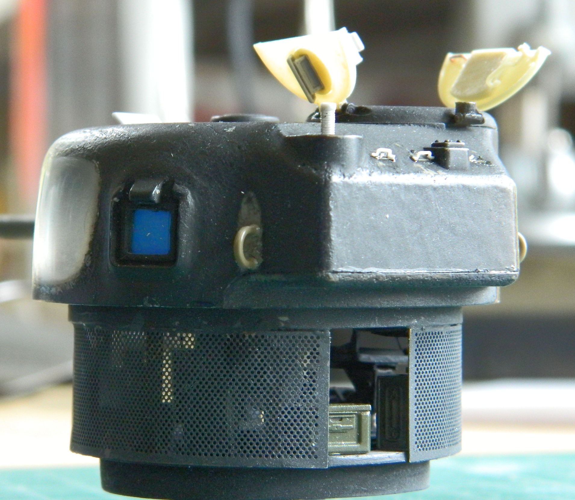
Having masked the commander’s hatch from the inside, I added the padding to the lip of the hatch opening:
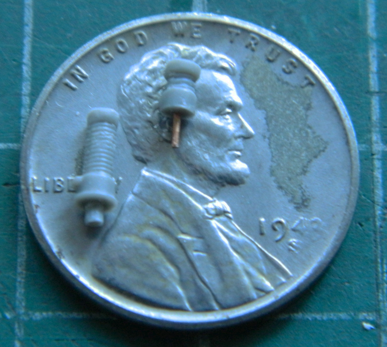
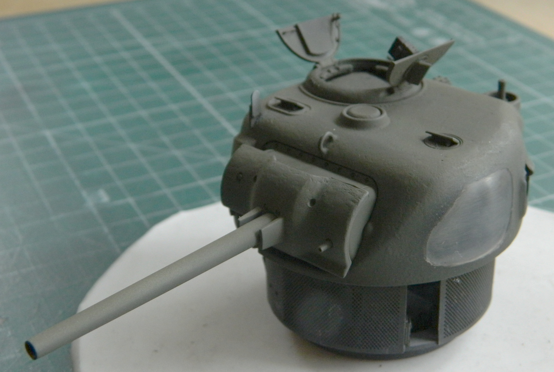
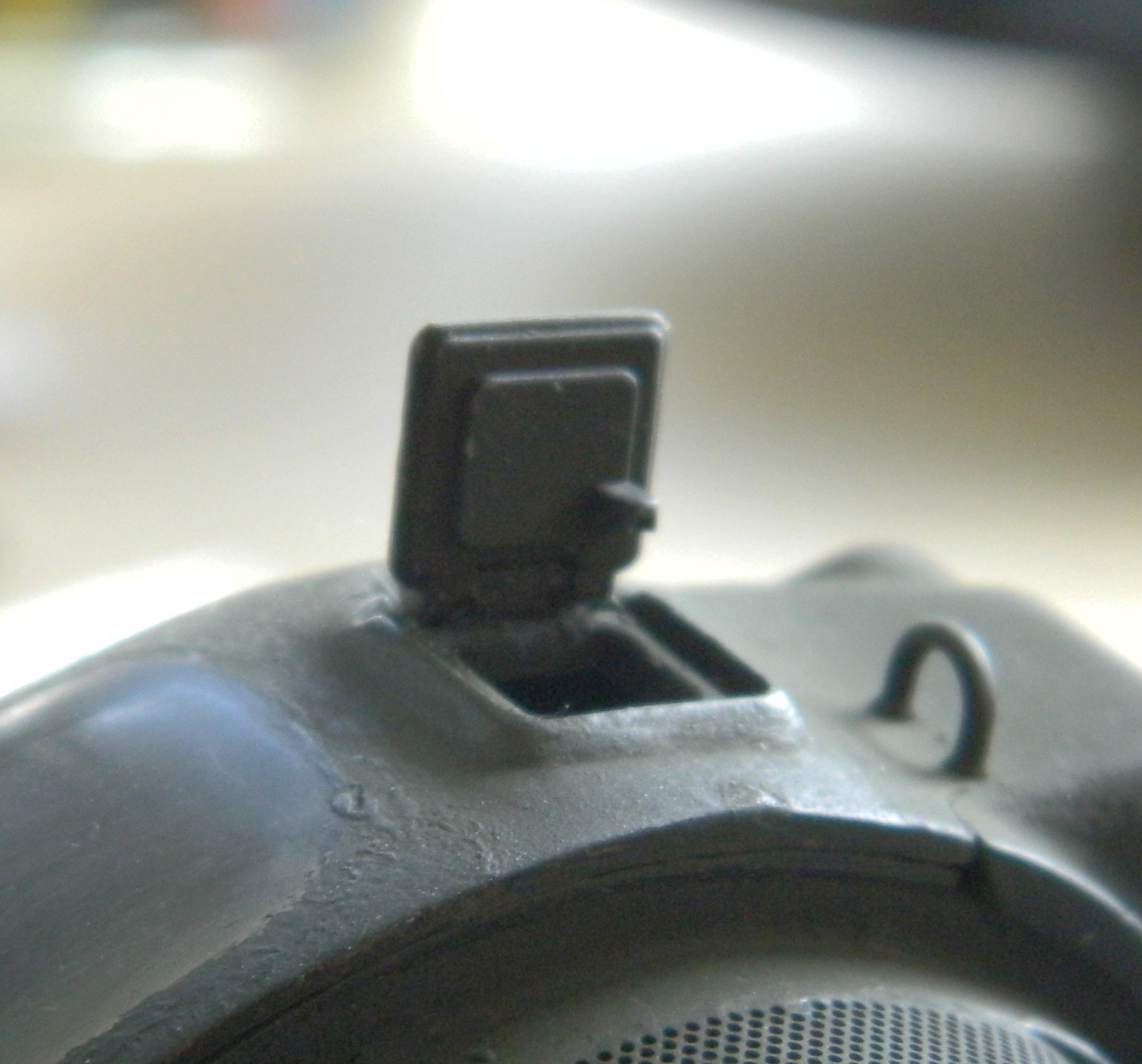
While I was working the top of the turret, I decided to add the front lifting loop and vane sight. Rather than over complicate things (probably just for the novelty of it), I used the kit’s loader and gunner periscopes; they were already dimensioned for the openings and only needed their heights adjusted, so only the tops of the periscopes were needed. There was an unwanted gap at the base of the vane sight which was remedied with 3M putty:

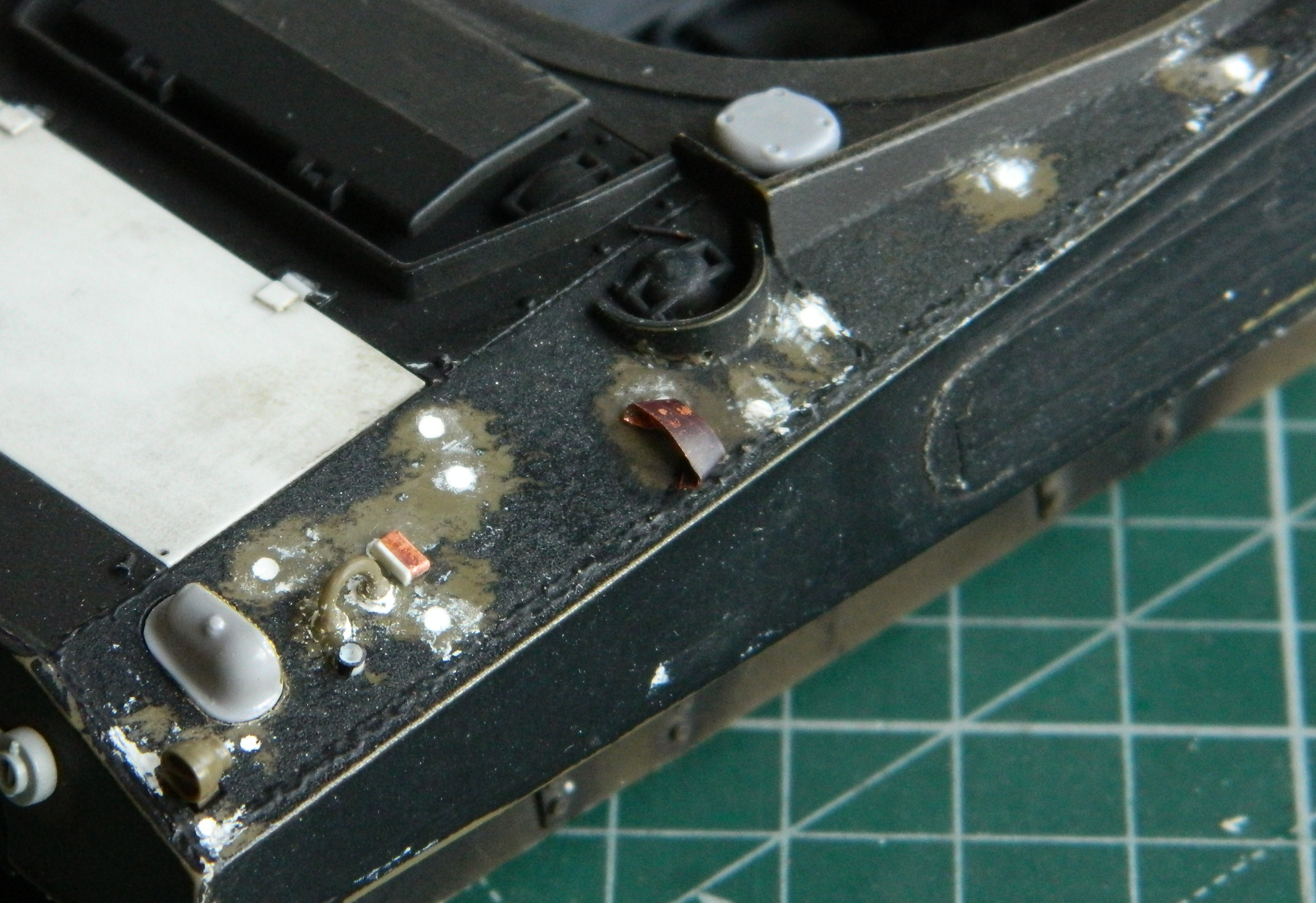
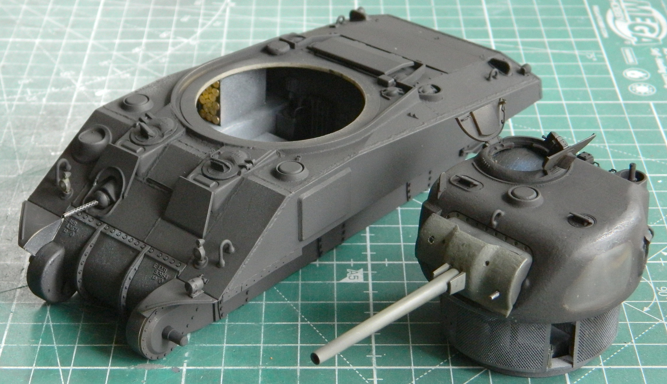
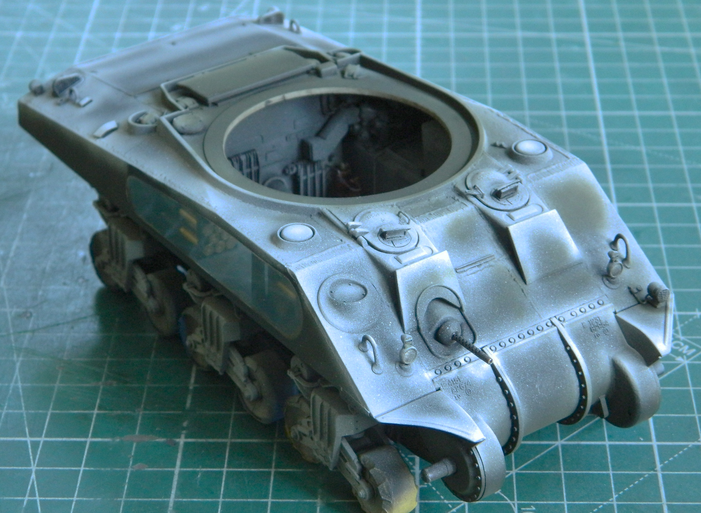
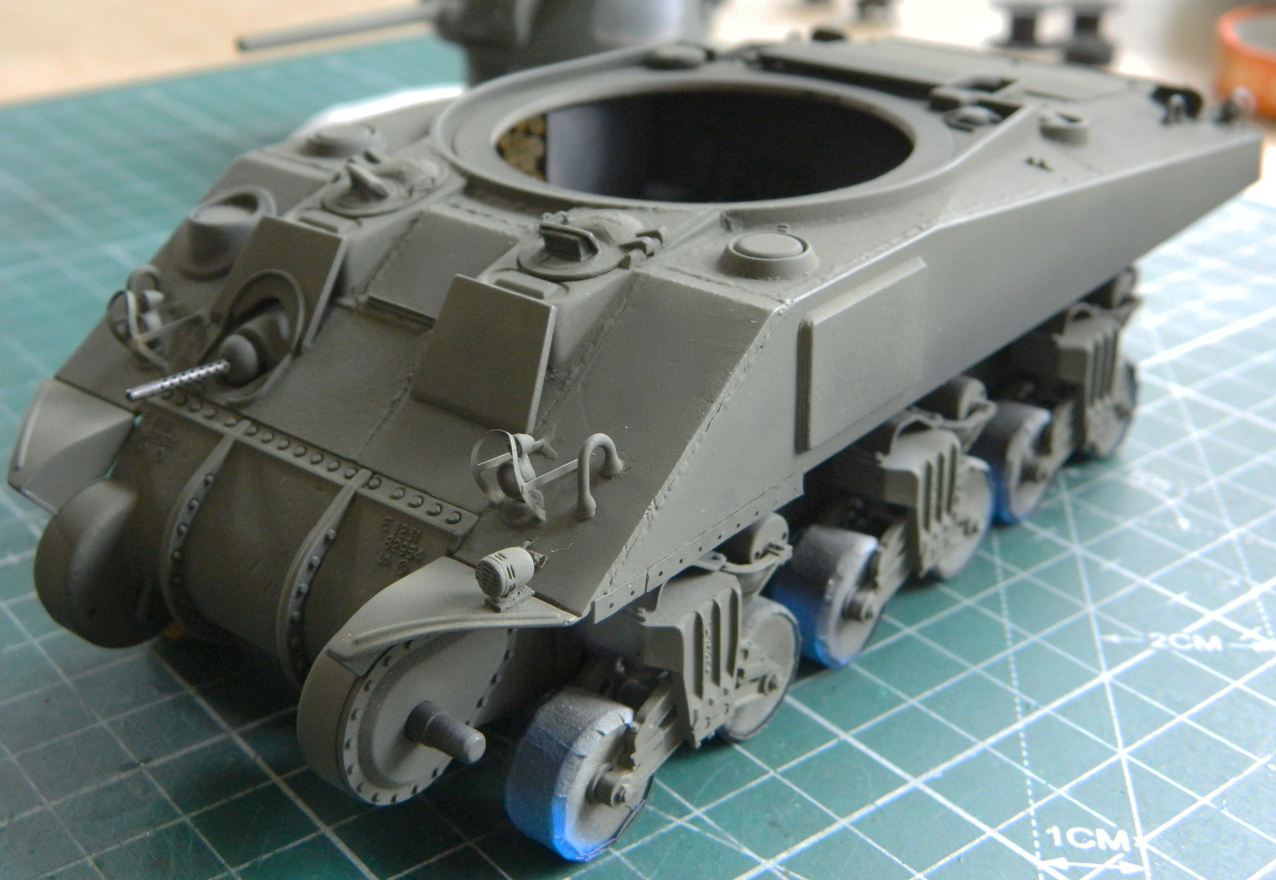
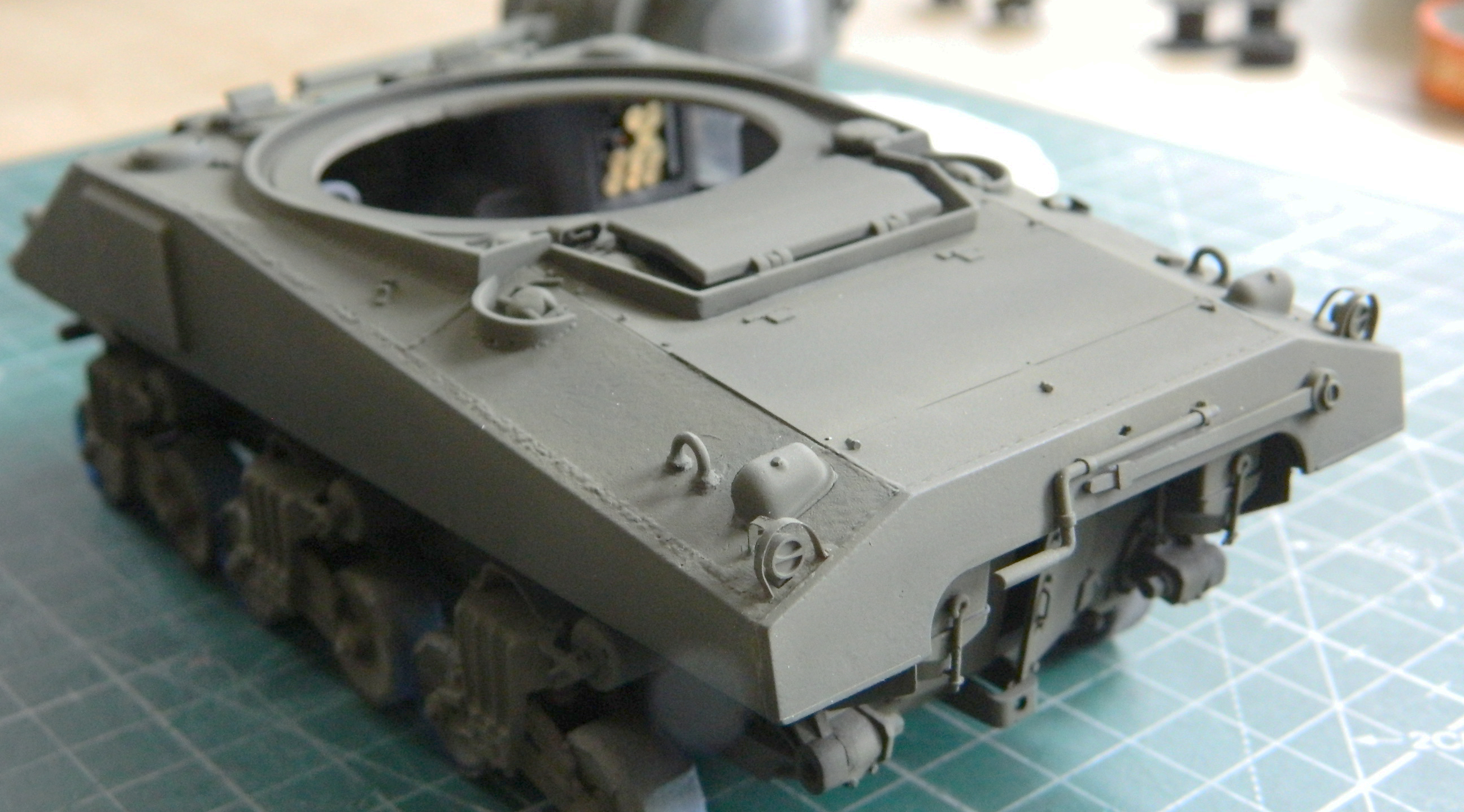
My references has shown a few Shermans that had vestiges of the mounting strip for the unused sand shields still in place. I used .005″ (.127mm) copper shim stock to replicate the remnants I’d seen in period reference photos, drilled the mounting holes, then trimmed and flattened the strips and installed unequal lengths at the front of the sponsons’ lower edges on both sides:


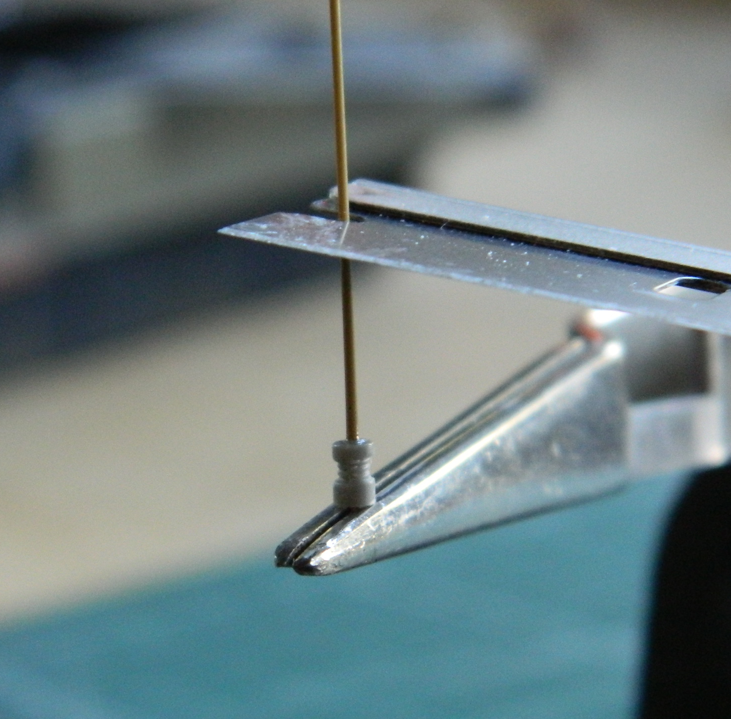
I stretched OD using a sprue from the kit 7mm in length for the radio antenna. I make my antennas detachable to lessen the chances of this part being snapped off. I used a Dragon antenna mount, cut it in two, added a wire pin to the antenna part and drilled a mounting hole in the antenna base:


The top of the upper piece was drilled to accept the antenna which was then clamped into a jeweler’s vise with the antenna propped into vertical orientation with a cutout on the edge of a single-edged razor blade while the glue cured:
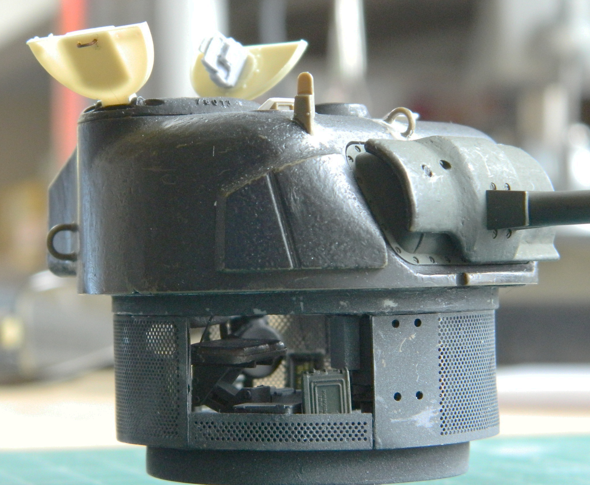
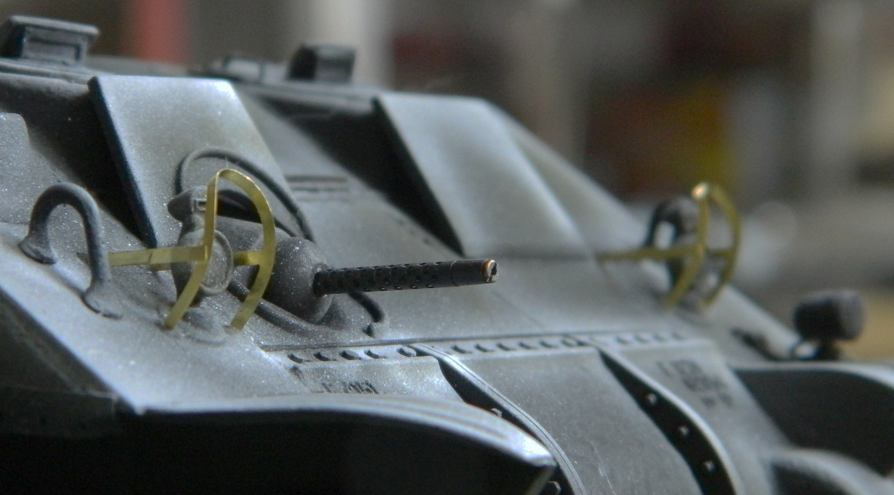
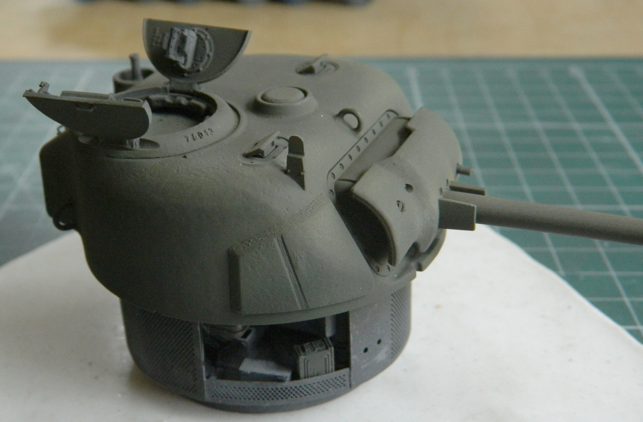
Assorted details were added to the turret’s exterior. The molded-on loops on top of the bustle (where the crew would frequently fix their rucksacks) were replaced with TMD’s small loops, the siren was added to the fender with a section of .015″ (.381mm) solder serving as its electrical feed and a TMD holding bracket. Periscope covers, lifting loops (another Dragon item from the spares inventory…though it wasn’t until too late that I discovered that ALCO tanks used a flat pedestal under their loops), a small PE “L” bracket was added, and the antenna base was glued into place. I used TMD’s periscope for the commander’s hatch by cutting the opening for it through the hatch:

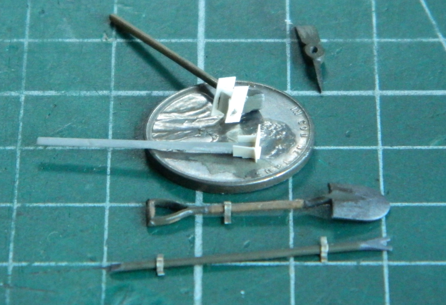
I started work on the pioneer tool mountings. As I’ve whined about before (and will probably whine about again), small details take a lot of time. When I make tool mounts, I’ll use both styrene and copper shim stock of .005″ (.127mm) in both cases. I use the shim stock when structure is required and styrene when it’s just (“just”?!) cosmetic:

The above photo shows how many tools get used for something essentially simple. The dividers mark out dimensions (and sometimes put down a line while doing so), scissors cut the shim stock (I used a razor blade and a small hammer…tapping the blade through the plastic…when I want a straight edge in plastic), a file so that by holding the copper with flat-face pliers I can file errancies created by old hands trying their best to make a straight cut (another ability I suspect lost to the passage of time), and tweezers to enable Fattie McFumblefingers to handle the sodding parts. And that’s all just for those little tools… I hold up the hoop and jump through it because it does impart a very nice effect:
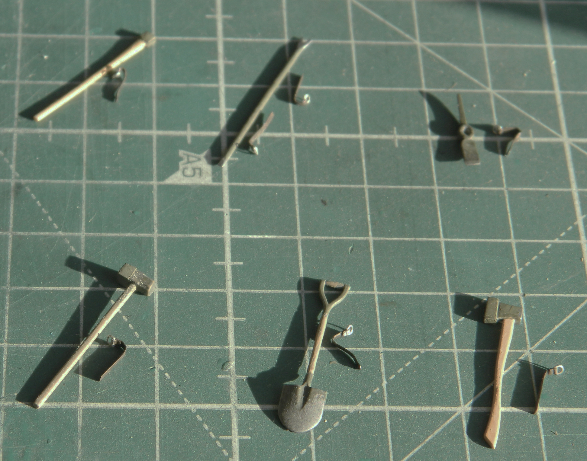
For the sledge hammer and shaft of the pickax, structure wasn’t needed, just appearance, so styrene was glued directly to the parts and then the excess trimmed away with the razor-blade-and-hammer trick once the glue had cured (the straps cut from lead foil weren’t used…I made better ones later and used those):
And of course the handle of the pickax broke off. It was glued back on (a few times) later.
What the work on the exterior of the turret and those annoying tools was really for was to allow my mind to ponder, consider, and ruminate on the idea of was it really time to add the turret basket to the turret? Well, at some point one must pull the trigger so I did just that:

For the record, I am not pleased with how the sides of the turret basket came out. Sufficiently displeased that I started plotting and planning how I would fix them. Before I could start, however, I got a good night’s sleep (my sleeping patterns anymore resemble a stopped clock and that “good night’s sleep” was my circadian version of that stopped clock being accurate twice a day…which means that for the other 22 hours it certainly is not) before I could start and realized that as the tank would be displayed, NObody would ever notice. The sides stay as they are and I continue to be displeased with them. (A metaphor for life, methinks.)
At this point I needed to decide if this thing was prepared for paint. Step one was to cover it with black (again) to make sure there wasn’t anything I’d overlooked. All the different colored bits were now all the same color. Before breaking out the color, I decided to see if I could get another good night’s sleep (and the answer was no, in case that’s of interest to you) before loading the airbrush with Tamiya XF-62 Olive Drab and going for it:
Satisfied that I hadn’t overlooked anything too obvious, I used Tamiya XF-2 Flat White to define where I wanted the highlights:

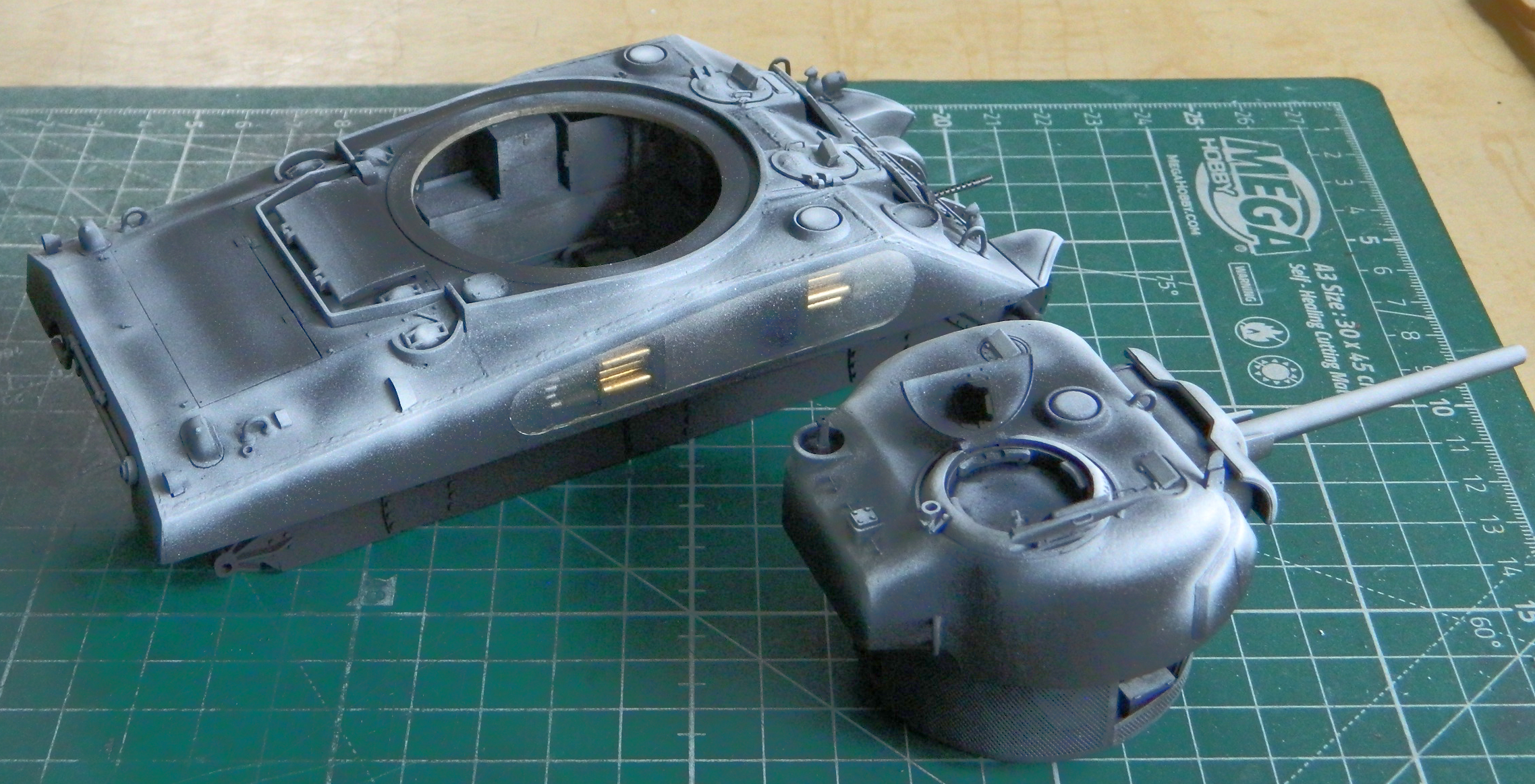
By misting on a color coat over something like this, there is a subtle difference between where the black is and where the white is. (Sometimes I wish more modelers were aware of the arcane notion of “subtlety”.)
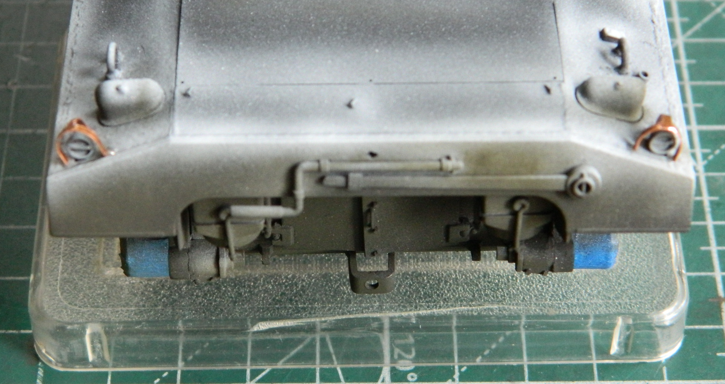
Although I had PE parts for the front headlight guards, I didn’t for the taillight guards. I resorted to .005″ (.127mm) again to make them:

I didn’t realize it at the time but I came to wish I’d built the headlight guards as well. The PE parts were far too thin and they were mashed, popped free, reshaped, reattached, and that whole process repeated too many times to count. Final takeaway is that the headlight guard were too damned thin. Next time I need to use these PE parts, I’ll use them to trace their shape onto shim stock:
Those headlight guards never looked that good again. Five minutes later I had to reshape them (the first time…there were many subsequent reshapings to come). The taillight guards fared better, only needing to be reshaped twice:
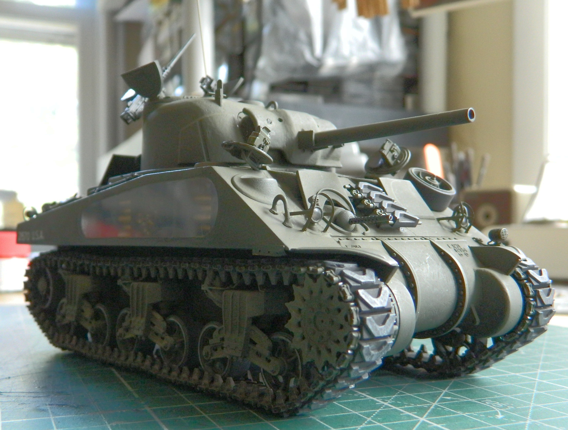
Then I used color-corrected Tamiya XF-62 with XF-2 added (about a 20-25% addition of white) and laid down the color coat. It’s not as evident in the photos as it is when looking at the model, but the highlighting worked well and the effect is subtle:

If you decide you want to try this method, a point to consider. If you lay down a thick enough color coat over the black/white paint, there’s no way you will see the highlighting. The color will eventually even out and all you’ve done is waste the white paint. As with many things in modeling, if you think that just one more pass will do it, stop there. If you’re correct and one more pass will do it, then go ahead. But please remember that it’s very easy to lay down enough color to obviate your attempt at highlighting. I mist the color coat on and don’t go for surface saturation. The thinness of the color coat over the black and white will allow the subtle differences of the surface to display what you’re after.
Before I threw color at this, I unmasked the clear sections. I had already put down several coats of paint and I didn’t want an obvious step at the point where opacity switched to transparency. Yes…there was overspray to clean up. The nice thing about acrylic paint (Tamiya’s specifically since that’s the paint I use about 99.8% of the time) is that it lifts easily off with a cotton swab soaked in denatured alcohol. And I didn’t go for a complete removal when i got to the edges where clear meets opaque. I got almost all the color off the clear sections and then cut a chisel tip onto a toothpick and scraped the color to the edge I wanted (I did the same thing for the headlights…it’s SO much easier than trying to mask little tiny areas with tape):

To see how my Clever Idea ™ of using clear panels turned out, I stuffed the turret into its place. I can honestly say that I am utterly unimpressed with the results of both the turret (the resin insert acts like a lens and not at all like a view port) and the hull (why am I surprised that the turret basket filled the view?!). A lot of effort for disappointing results and not something I’m ever likely to do again. It’s just a gimmick and one not worth my time for the results.
This is how we learn.
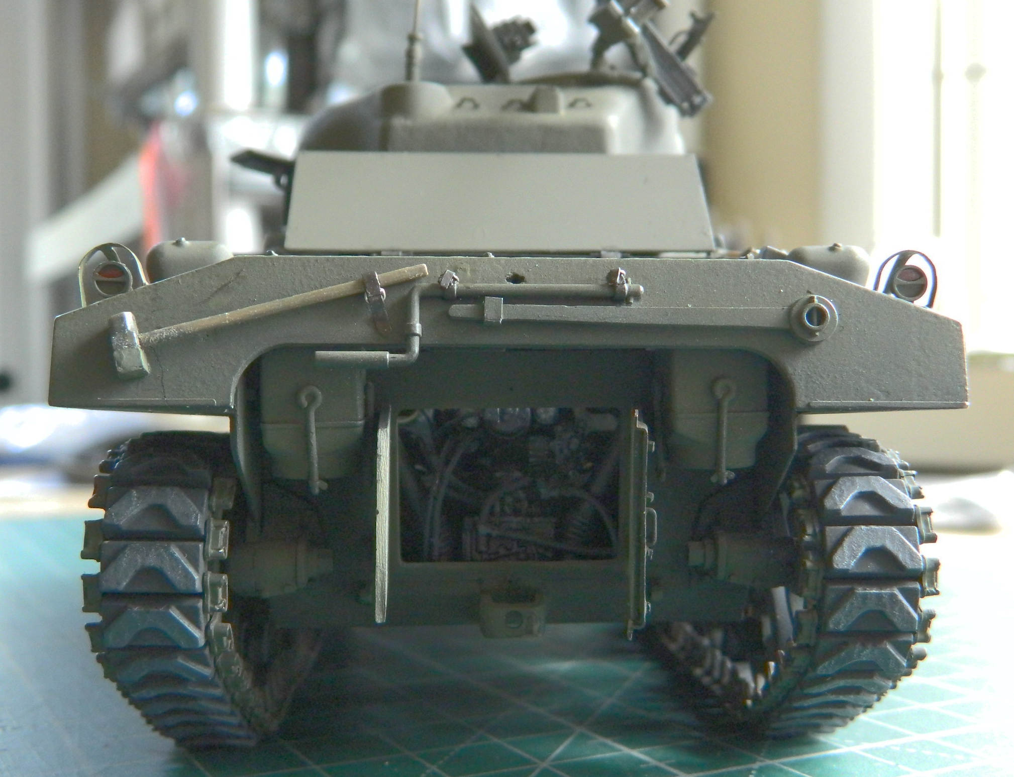
By the time of D-Day Normandy, the T48 rubber-chevron tracks were quite common (and were the most produced of all the track shoes used for Sherman and Sherman-derived vehicles). Steel tracks last longer, but they are absolute sodding hell on paved surfaces and can turn a paved road into a gravel path in short order. On a route march over paved surfaces with a company of tanks equipped with steel track surfaces, I don’t know when the pavement turns to gravel. I would guess that the first tanks of a 15-vehicle tank company had a smoother time of things. I rather doubt that the 15th tank did. And regardless of how smooth the ride of the tanks, any subsequent use of that road would be as much fun as I find scribing panel lines to be. None. The initial track shoes were the T41 rubber tracks. The shoes were simple rubber blocks without tread and sufficiently thick enough on both sides to be reversible. Worn tracks? Simple (if that word could be used to describe putting new tracks on any tank). Turn them over. You know, all 76-79 shoes, unbolt all the track horns (the guides on either side of the track), turn the shoes over, all the track horns bolted back on, and reattach the tracks. Simple, right? You bet. But they didn’t chew up pavement. They also didn’t offer much grip off the pavement, especially in mud. (There was a variant of this track shoe, the T51 shoe, which was also a rubber block but that one wasn’t reversible.) Chevron tracks, tracks with V-shaped contact area, offered better off-road traction. There were a few different types of this sort of shoe and the steel variants all did Bad Things to pavement.
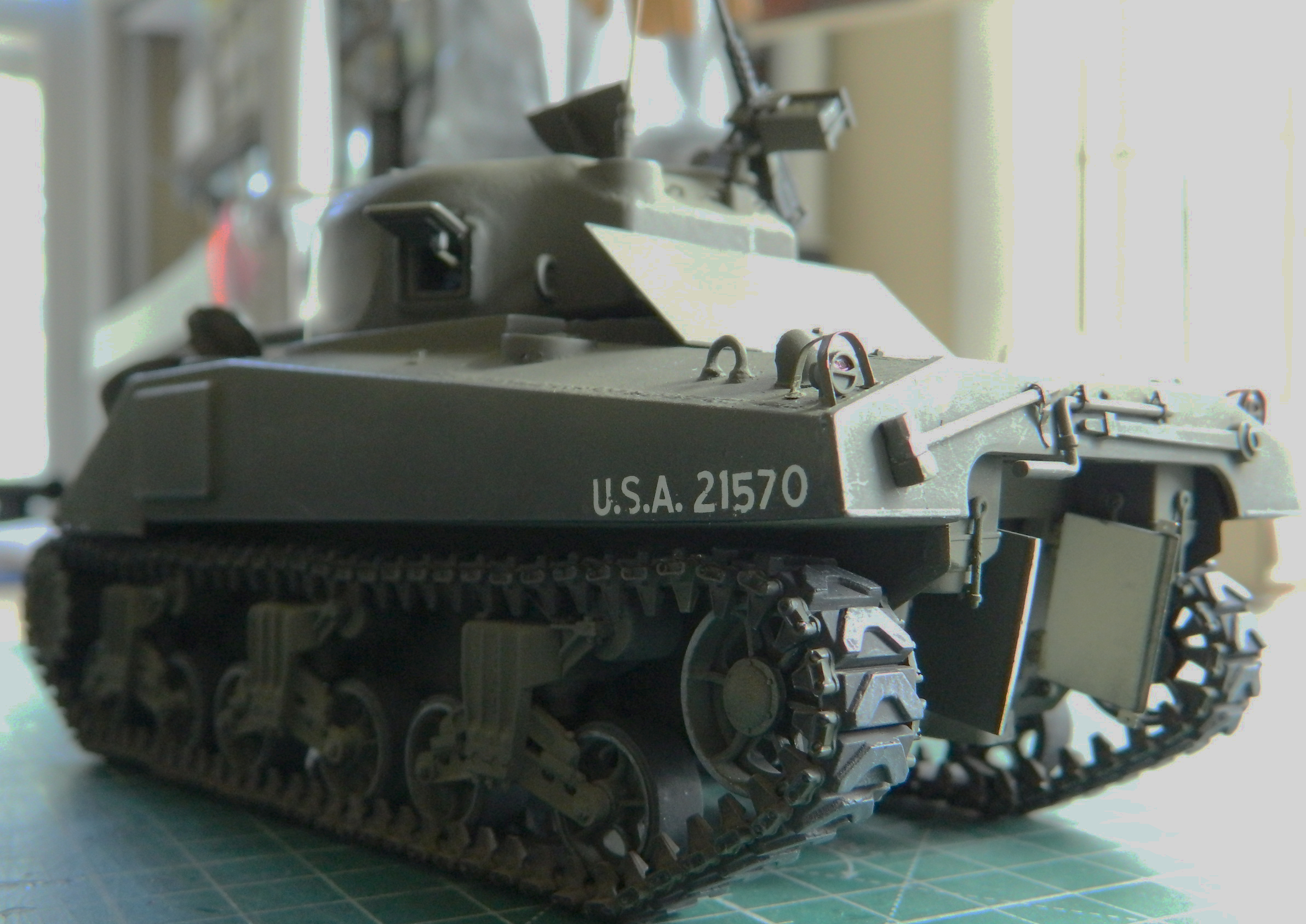
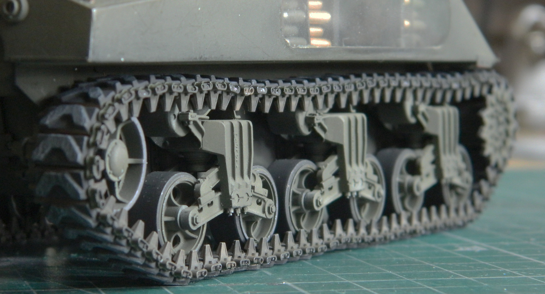
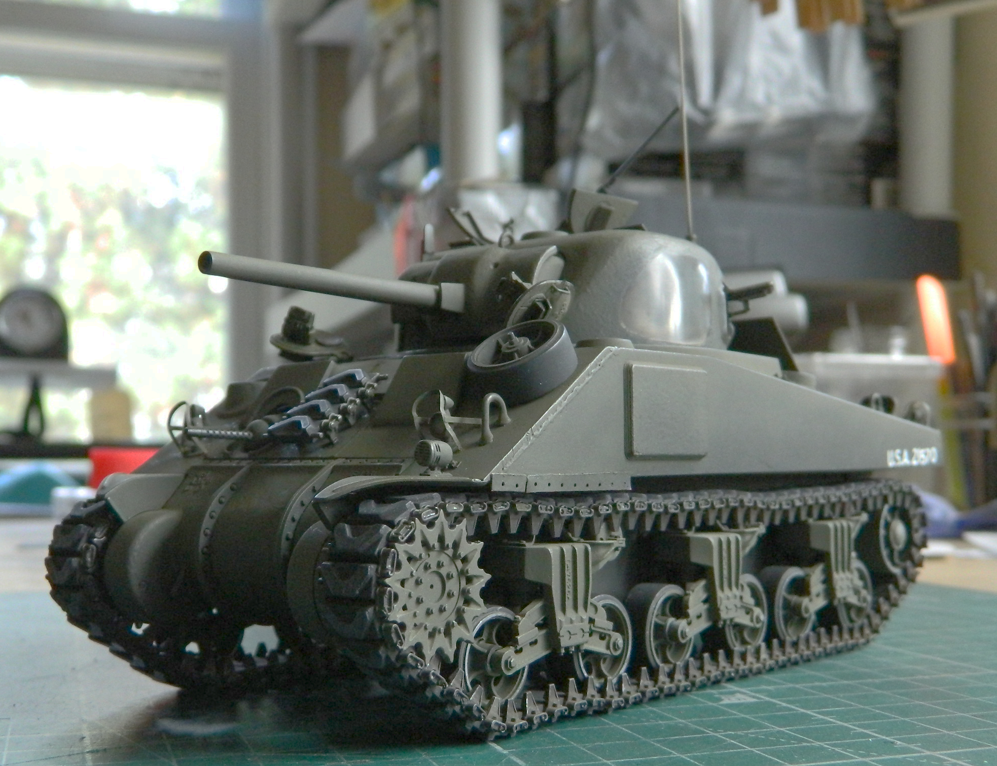
I’m modeling this one as a “Normandy” tank (and specifically as the 3rd Armored Division, 32nd Armored Battalion tanks were equipped, as you’ll see later with a spare road wheel and T48 track link hung onto the glacis). A tank that had already been deployed, recovered, and put through the “Blitz” program in England. This program updated older tanks with added welded-on supplemental armor to the sponson sides and turret (in front of the gunner’s position), in front of the driver and co-driver hoods, deleted racks in the turret for ready round storage (major fire hazard), new engines, differentials (where needed…many tanks with three-piece differentials landed on Normandy beaches), and some other upgrades. It was easier to take a tank that had already been transported across the Atlantic (and Mediterranean), recover it if it had been knocked out (but not burned because the heat of the fire removed any “armor” effect the steel had), and bring it up to the current standard of production line tanks as much as was possible. A lot of hardware and machinery was necessary for the invasion so anything that would meet service requirements was used. So my thought is that the tank I’m building was either first deployed in North Africa or the Italian campaign, returned to England, and “Blitzed” before being re-issued for the invasion of France.
All that was to say that this tank would have rolled off the LST on T48 tracks (and being as it was 3rd. Armor, 32 Battalion, they went ashore June 9). Because of training, those tracks wouldn’t be new anymore. Panda Plastics is my go-to source for Sherman tracks. They have a good selection (including tracks that have had all the rubber burned away, leaving the steel inner structure exposed, if you need a set of those for a diorama of a burned Sherman) and one is of worn-but-still-serviceable T48 tracks like the set I’m using.
I had thought that I’d paint the tracks with tan colored dirt overall with just the contact areas of the chevrons showing rubber. Okay…so how do I paint those things? I can’t just mask off the contact areas because rubber compresses and the edge of the contact areas creates a soft edge between worn and just dirty track surfaces and masking those things would leave a sharp division. Oh. Yeah. Before I forget, there are about 76 shoes on each side, too. And this idea had been rattling around my bald noggin for a few hundred hours while I worked on everything else. As the time approached, I needed to figure out a way to mask these things…oh. Wait. Do I have to mask them or is there a different way I could get what I want?
On one of my (dreaded) (am I over using that word?) trips to market, I passed through the make up section. Oh look! Micro-cell foam wedges used to blend make up! I wonder if I could paint the tracks the dirty color and then used a square-cut foam block as a rubber stamp is used to apply the rubber-colored paint? Dip it in color and dab it onto the wear areas? I took a section of kit-supplied spare shoes and tried it:
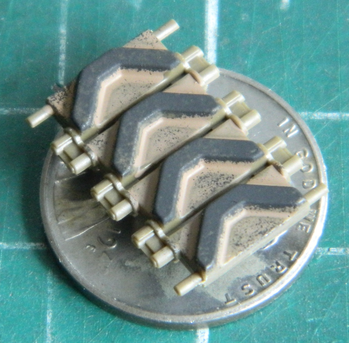
Worked great and wouldn’t take me many tedious weeks of masking each shoe individually! And since the foam is compressible the way the chevrons were compressible, there was enough coverage of the other parts of the shoe’s face to replicate a realistic wear pattern! For a short period of time I was ecstatic…or at least my reserved version of it. I think I might have even smiled. Once. (Though in fairness, that could have been gas.) So I concocted a mix of paints to paint the tracks as I had the test links and shot the tracks:

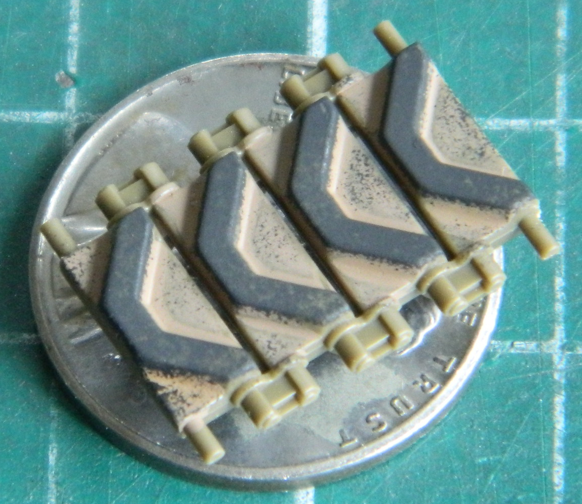
I almost engaged in massive reverse peristalsis (as in, puked) when I saw what I ended up with. No. If I was doing a tank that had been out in the field for a few weeks, maybe. Maybe. As a track fresh off the boat? No. My next Clever Plan ™ required me to paint the rubber tracks rubber using Tamiya XF-85 Rubber (though Tamiya’s XF-69 NATO Black also works well to replicate rubber). I had an idea that I could use the rubber-stamp notion using a grayish paint or use a white pencil to replicate wear and set it off from the supposedly-unworn backing. The penciled track is on top, the rubber-stamp track is at the bottom:

Rubber wears like an eraser does, by being scraped and dragged across a surface. The painted tracks didn’t look like they’d been dragged and the penciled tracks did, they looked like they passed over a puddle of gray paint. I went with the penciled tracks and I’m as pleased as this process allowed.
I brush-painted the outside of all the track horns OD Green and ended up with something that would work well…until I tried to bend them. Ever try to open a window that had been “painted closed”? The paint had insinuated itself inside of some of the track shoes where the pins go into the track horns and locked them as tightly as a window that was painted closed.
I took a section of about 12 shoes that had broken off when I tried to bend them and soaked them in denatured alcohol for two days and they refused to budge, though there were easily snapped.
The word “assumption” is used in the title for this post and here’s where I made the mistaken assumption. Because I had one run of track that was now missing a dozen or so links, I assumed that I was a dozen or so links short on the other side. I ordered another set of tracks from Panda Plastics and played Zelda for a week or so. One morning, propped up in the shop with my requisite bucket of coffee, I figured that I might as well put on the run of tracks that hadn’t locked up. When I did I realized that I had far more track than I needed. But did I have enough track to make up for the track length that was missing?
Yup:
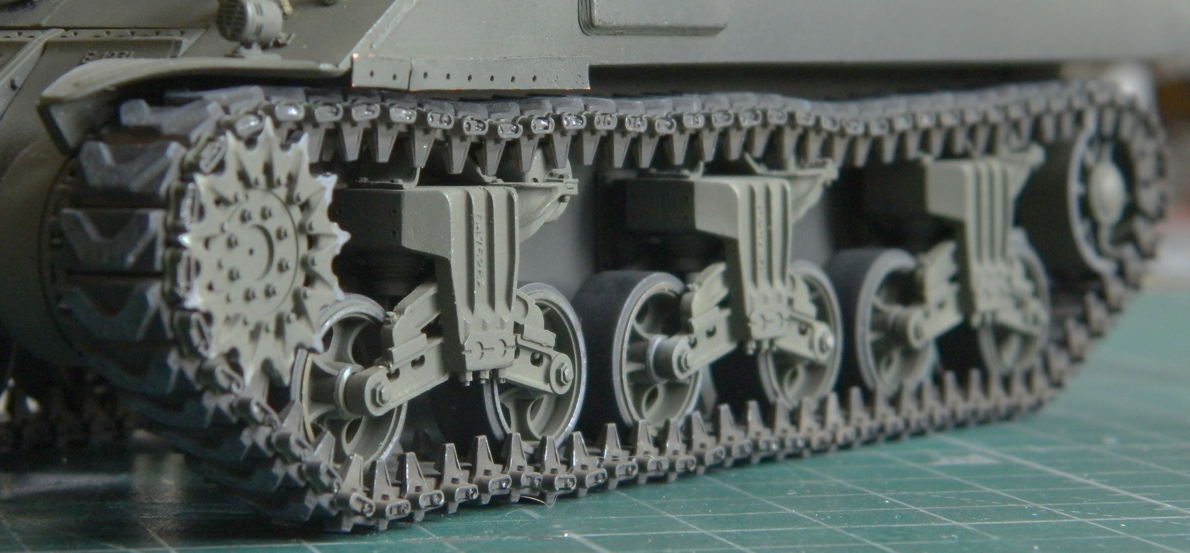
And here I thought I’d already learned to look first…evidently I needed the reminder. (And the paint on the outside of the drive sprocket didn’t wear like that, so I fixed it.)
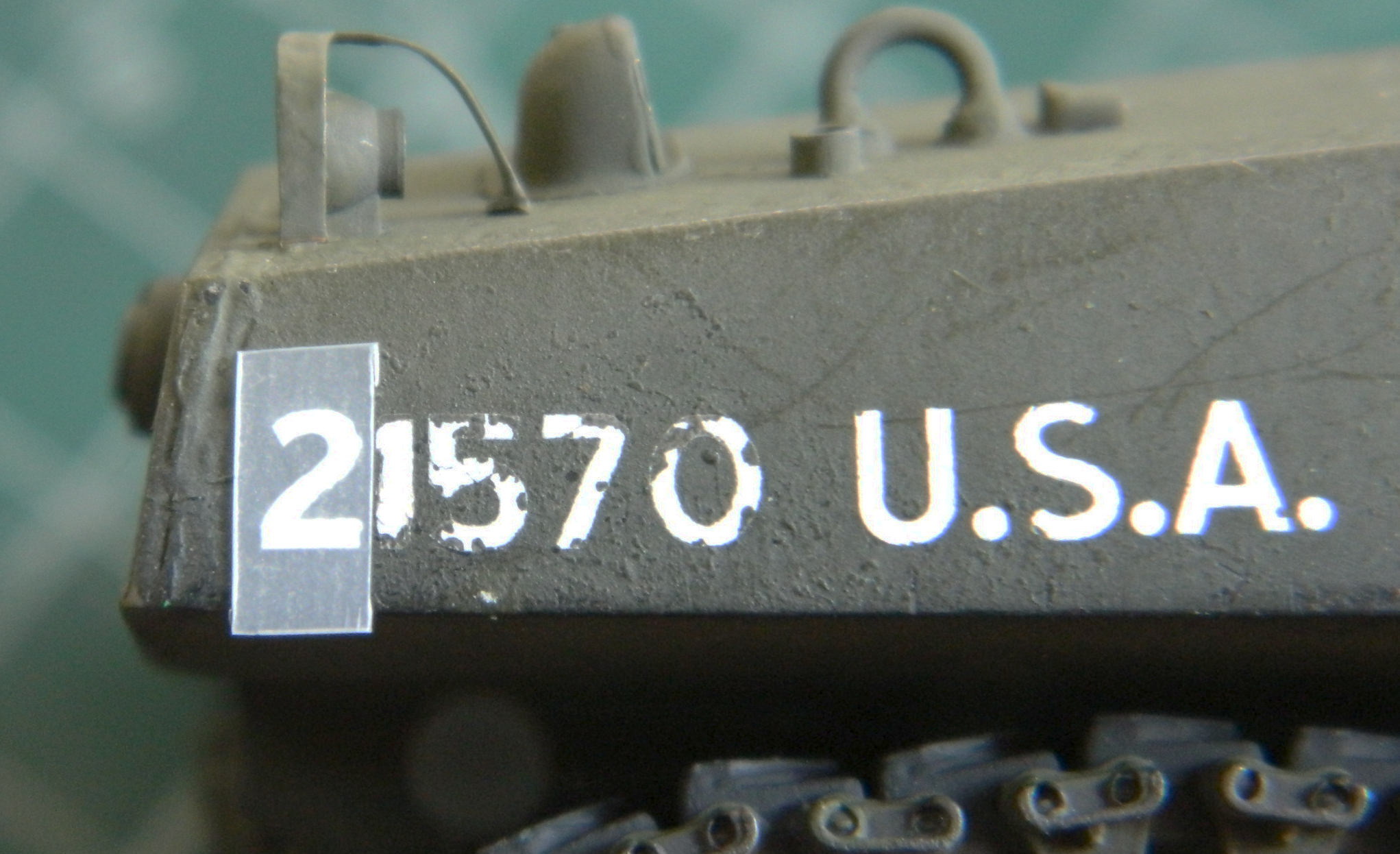
Now that I have an extra set of T48 tracks in stock, it was time to add minimal markings. At the time of their deployment (pre-Operation Cobra), 3rd Armored 32 Battalion didn’t have stars that I could see in the half-dozen reference photos I could find so I didn’t add them. They did have serial numbers and I used an old set of Archer Transfers to cobble together a fictitious number:

As you can see, it didn’t go well. It didn’t even go adequately. Having more numbers, I tried transferring the same numbers over the first ones:
That didn’t go well either:
I tried touching up the many misalignments with paint and though it was better, my boat wasn’t floating. Doing the other side was even worse (as you’ll see later). If that wasn’t enough “enjoyment,” it took four hours to do something this lousy. They day came to an end, I managed to feed myself and find the bedroom in less than six tries. The next morning I looked at the garbage I had done and using scotch tape, pulled the numbers off. That was the only easy part of it all…and it shouldn’t have been. That led me to think that what I had was new old stock and that the adhesives just didn’t work well anymore. I briefly considered the more typical approach, decals, and decided to hell with it. So my tank has no numbers. I’ll live (for now).
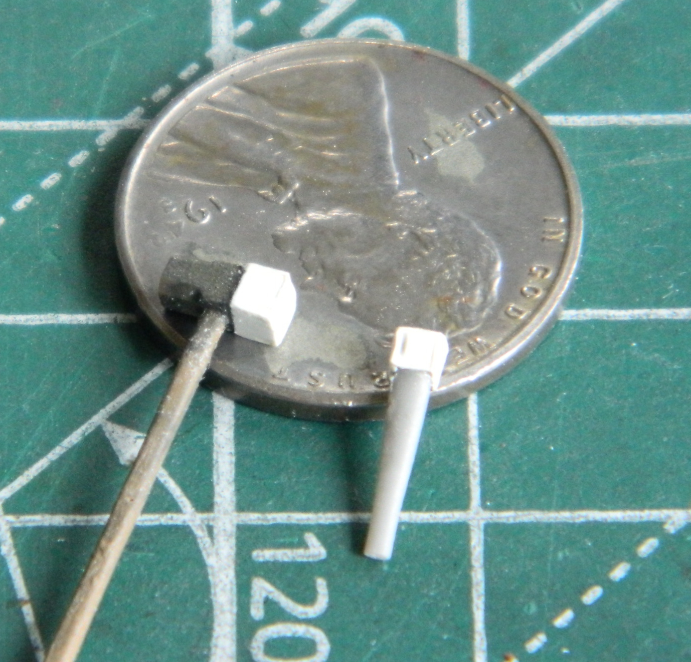
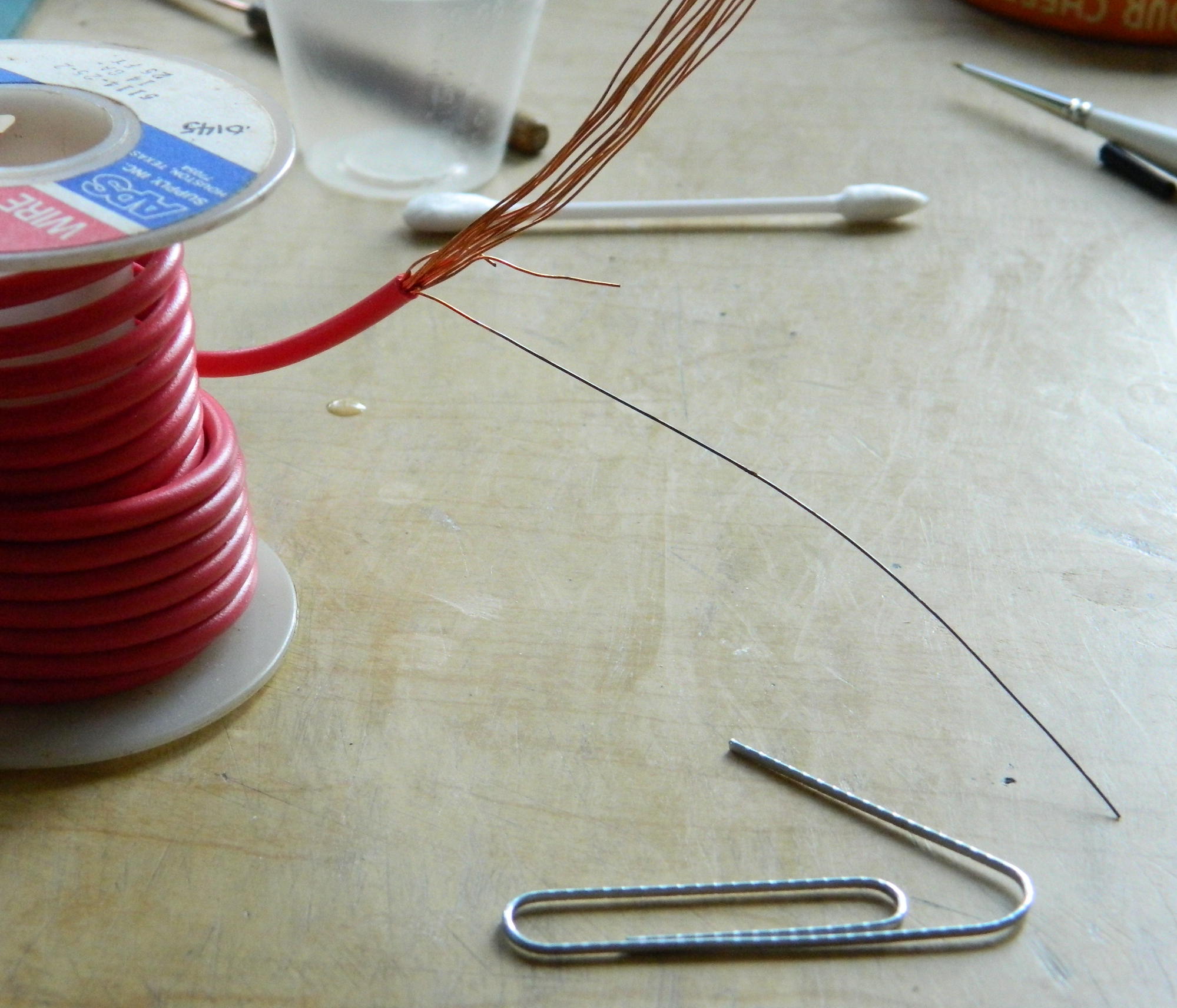
Then it was time to mount the pioneer tools. To do that, I needed to make straps and buckles. I started by annealing copper wire so that it would bend easier, and I modified a paperclip to use as a mandrel to wrap the wire around so that I could cut them into square links for buckles:

Though it worked well enough, the result was sufficiently out-of-scale as to be useless. Next I tried using .010″ (.254mm) solder around the same mandrel and ended up with something that would work (though they’re FRAGILE). I cut lead foil into strips, painted them my mixture of “black leather” (using Tamiya paints, the formula is X-18 Semi-Gloss Black 5 parts and XF-64 Red Brown 4 parts), and ended up with all the straps/buckles I need to mount the tools:
Then I added the pistol port hatch:
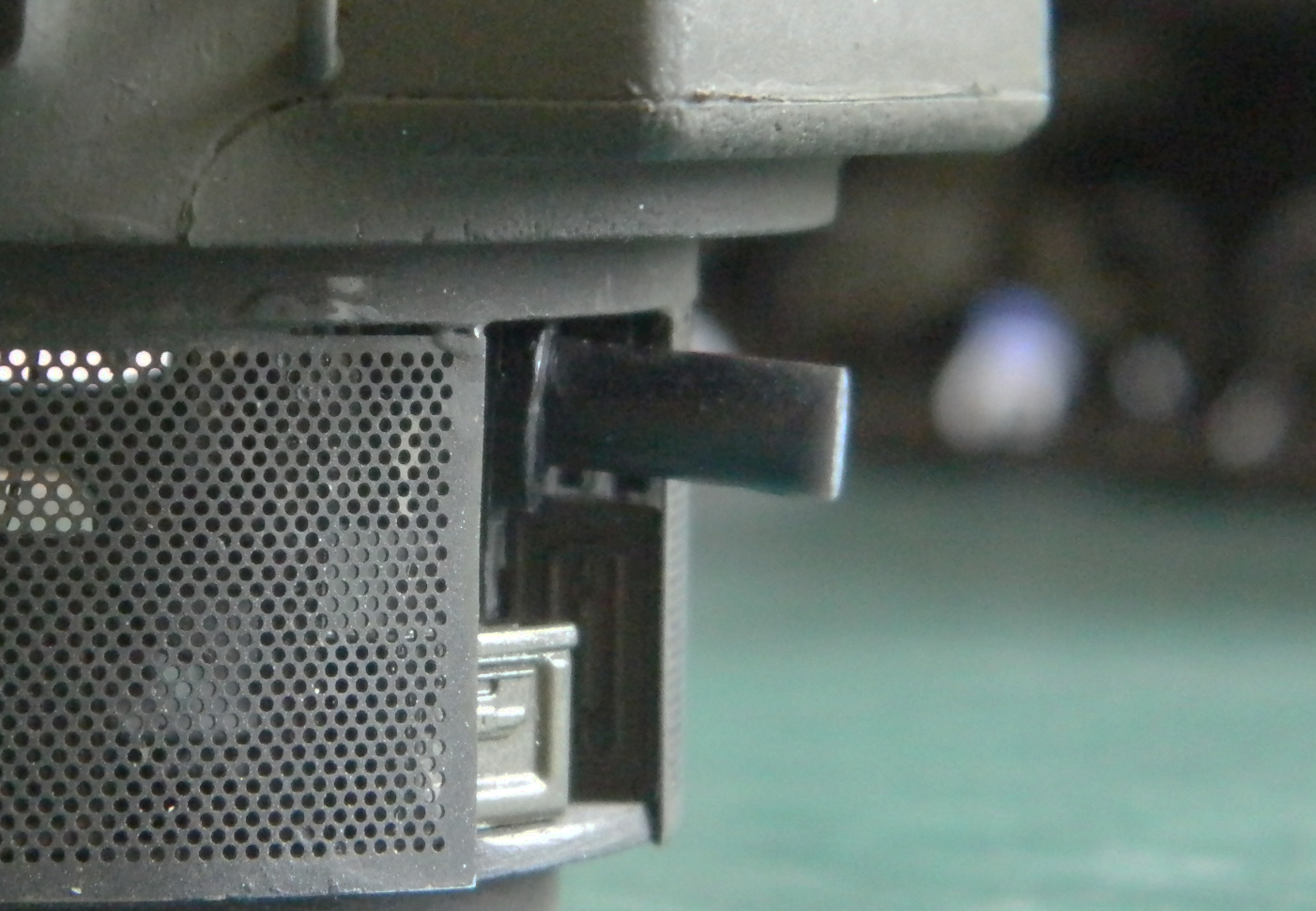
While I was moving and rolling the turret assembly around, I heard…a rattle?! What the aerial intercourse is RATTLING IN MY SUPPOSEDLY FINISHED TURRET?
Nothing major. Just the breech of the main gun! The cylinder sticking out of the turret basket is the errant breech:
::facepalm::
This turret was, I thought, done. I know that turret basket will not come loose in a reusable manner, so that approach is out. The only other approach (that doesn’t involve a big hammer) is to pop the gun out through the front of the turret (which is the way it went in). I broke out in flop-sweat. Taking time to clam down, I wandered around the house engaging in very colorful (and anatomically unlikely) invective (yes…that’s my version of “calming down”…which rarely, though not always, involves a hammer). Suitably calmed (uh huh…), I took the thinnest steel tool I have that would have enough torsional rigidity to not only get into that really small gap between the turret and the gun mount, a #15 scalpel, and pried that bastid out of there:

If you look at the upper left of the opening in the front of the turret, on the turret face you can see where the paint chipped. I thought that I’d probably give myself several days of having to repair and repaint the damage that I’d do getting that [EXPLETIVE DELETED] gun out of there. Nope…just a wee nick in the paint and I spent more time stirring the paint than fixing the nicked paint took. It’s a win and I’ll take it. And of course I examined the errant breech closely to see how the glue failed. Well, the glue didn’t fail because I forgot to glue it in to begin with.
Brain fade. Insidious.
But I assure you that it’s glued in now.
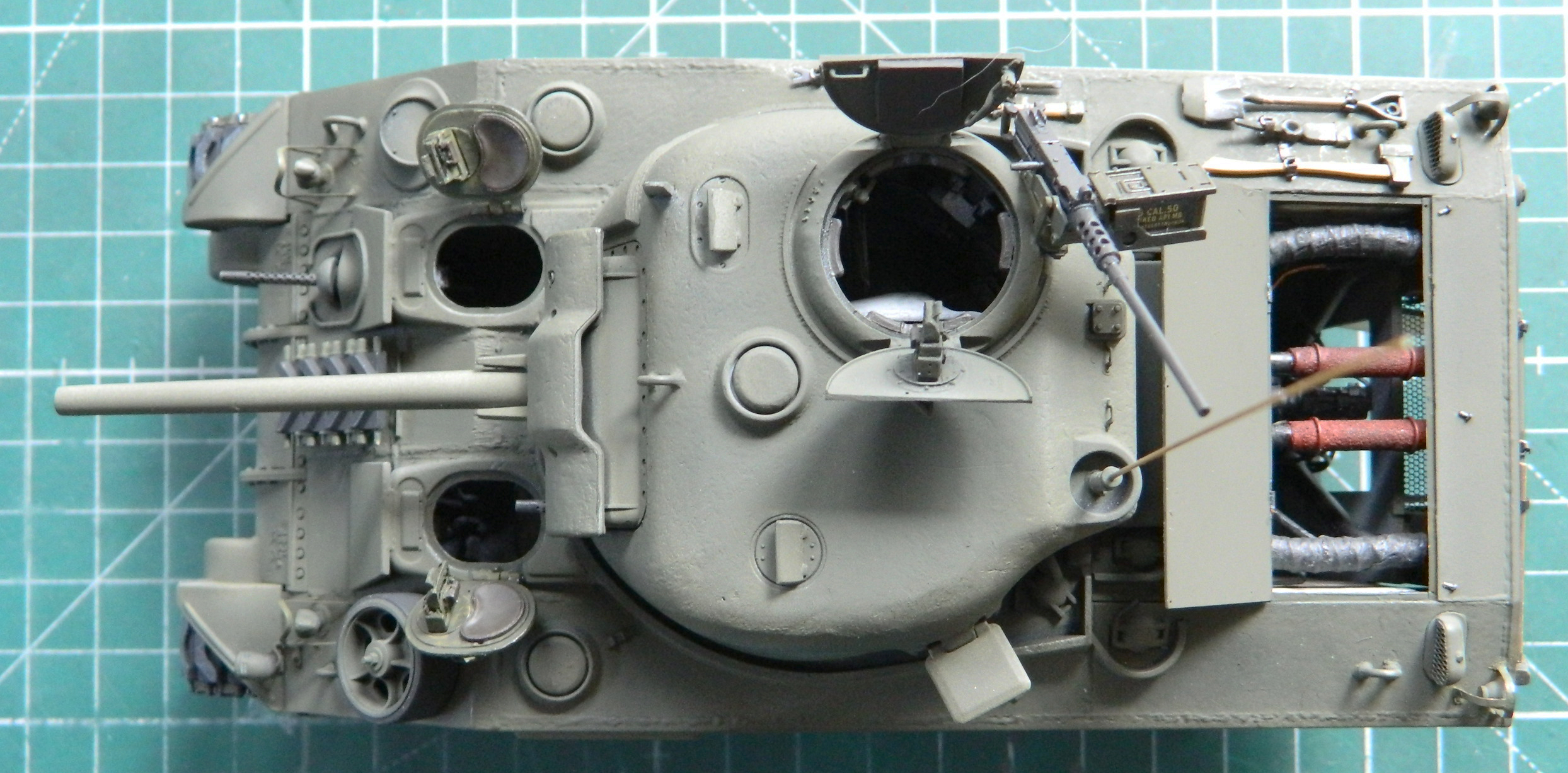
So I glued the .50 caliber (1.27mm) in place and went to bed. The next morning, all pleased and flushed with my victory over, well, me not gluing the fornicating breech in, I looked at the machine gun mount and saw this:

When I walked away from the bench the previous evening, that mount was as perpendicular to the hatch ring as it was supposed to be. Seeing as the gun mount is plastic and the turret ring is resin, I of course used superglue to attach it. Clearly it had not set when I mistakenly thought it had. The mount itself is very thin and delicate and I know, KNOW, I used enough glue to hold that thing in place until the sun’s death when it will expand and incinerate the planet I’m sitting on. No way I’m going to be able to twist that thing out of there. So I took my thinnest RB razor saw, cut it free, and after making both meeting faces parallel to the resin casting, drilled the mount and socket and installed a pin. It’s now perpendicular and will stay perpendicular.
With that, this one is done, in spite of its last-minute resistances, and is finished as if it’s in a museum (these photos were taken when it still had its lousy serial numbers on it):

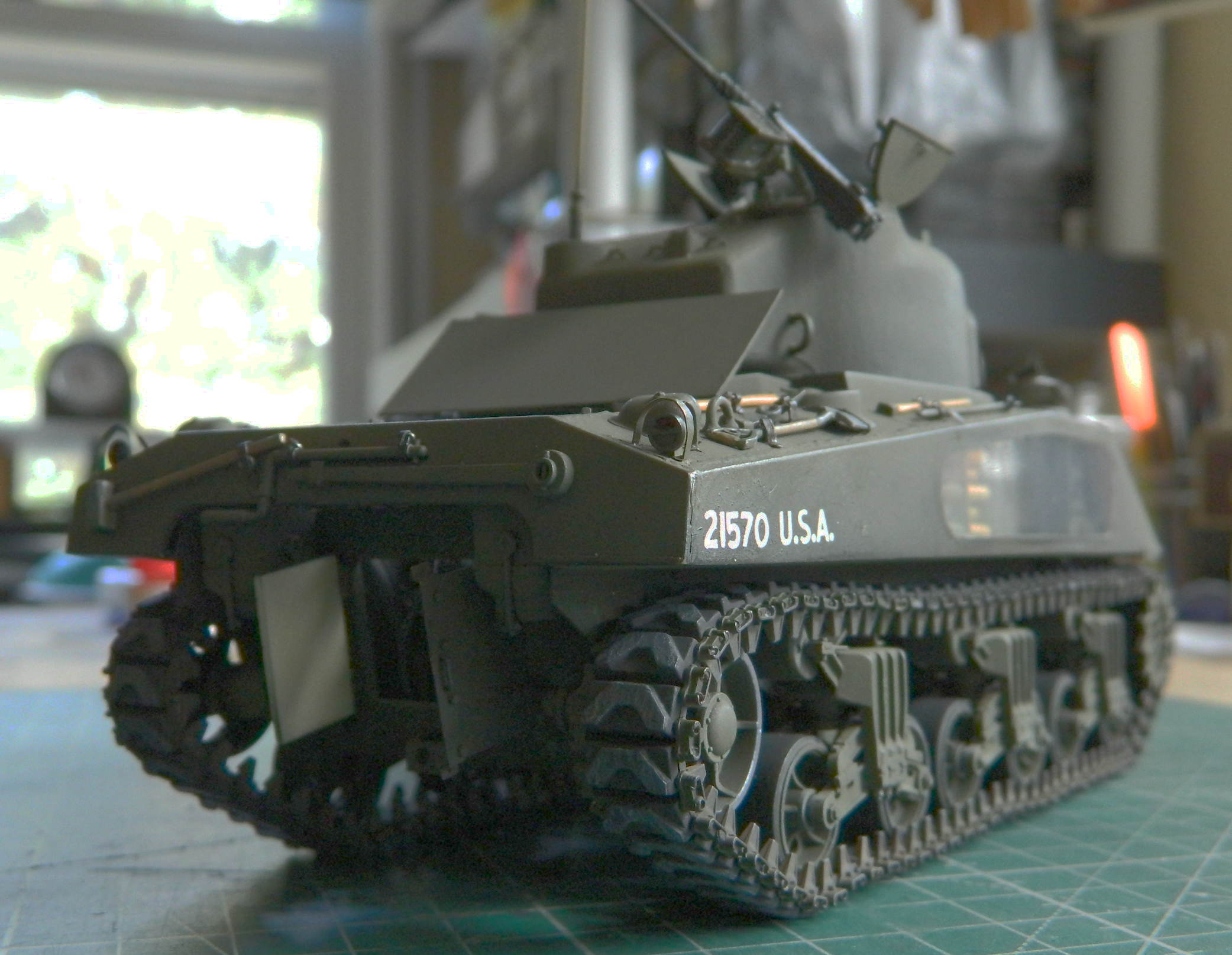
See? I told you the numbers were lousy: