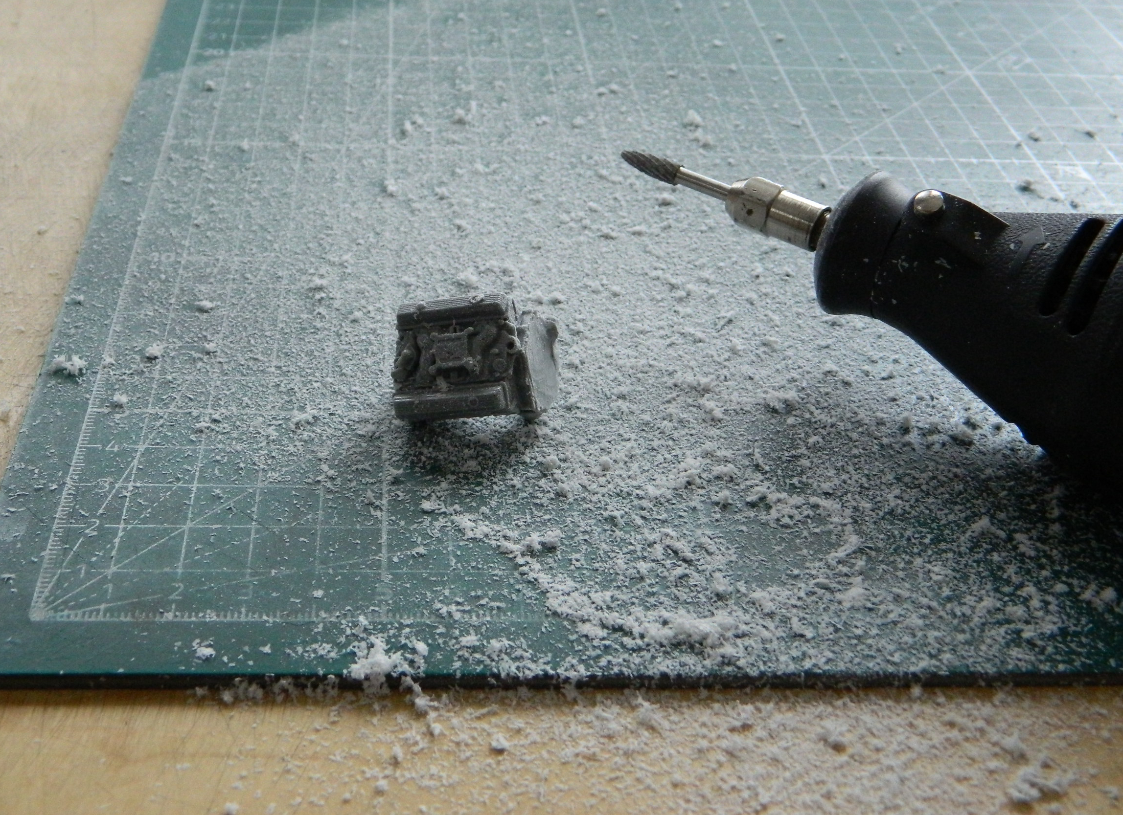
Since I need the engine/transaxle to define where the interior can fit and where the body needs to be modified, I started this month’s work by removing the bellhousing from the engine. I’d started to use a saw but on that particular morning my hands weren’t as steady as the job required. I took out the Dremel and made a dusty mess of things:
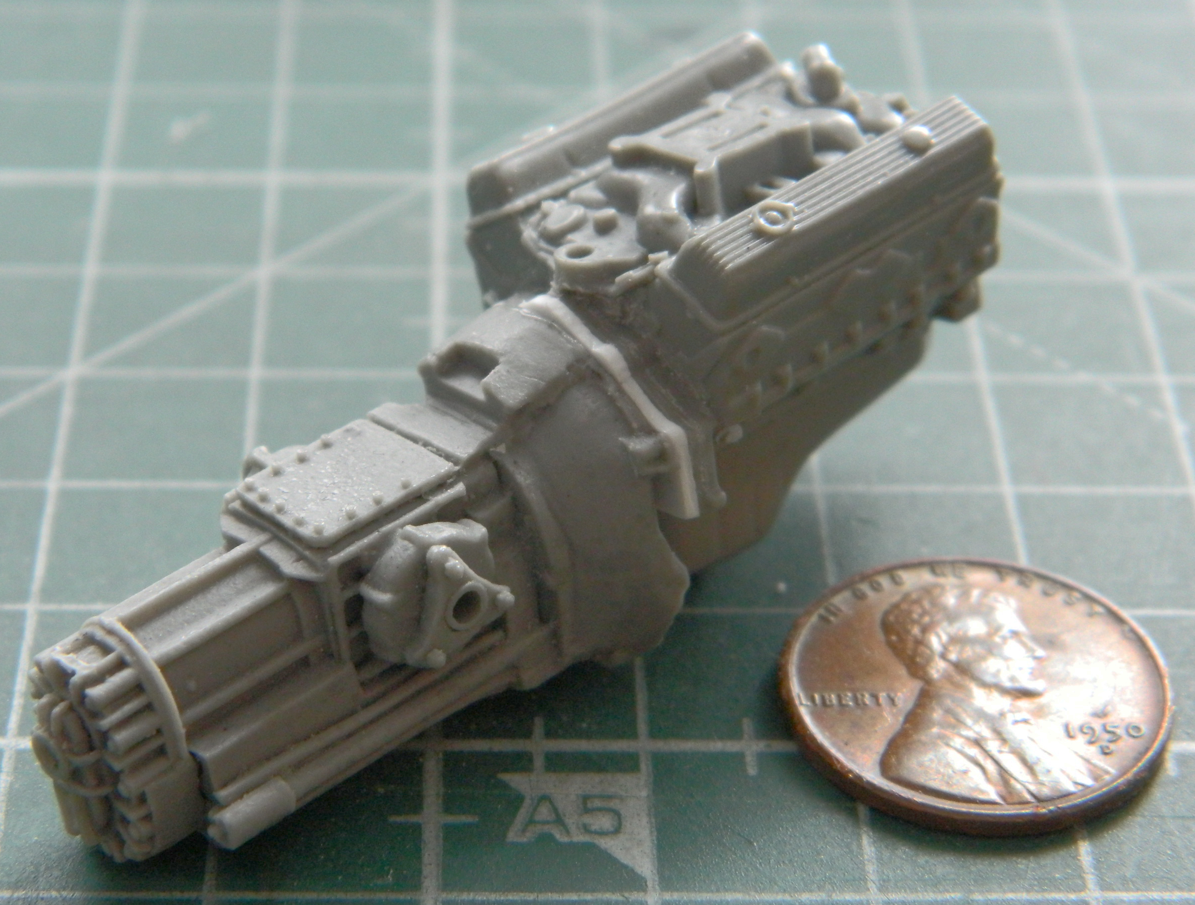
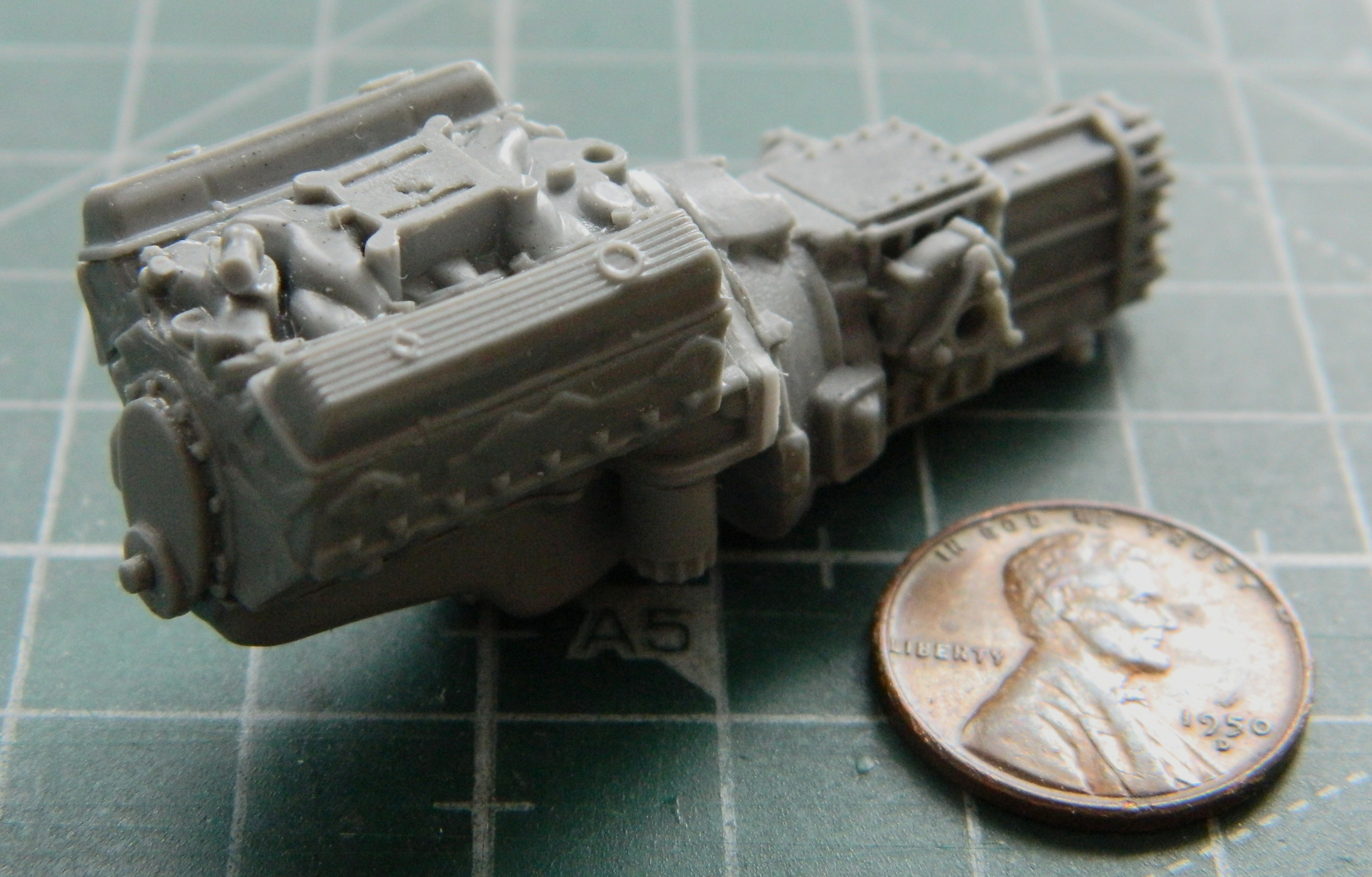
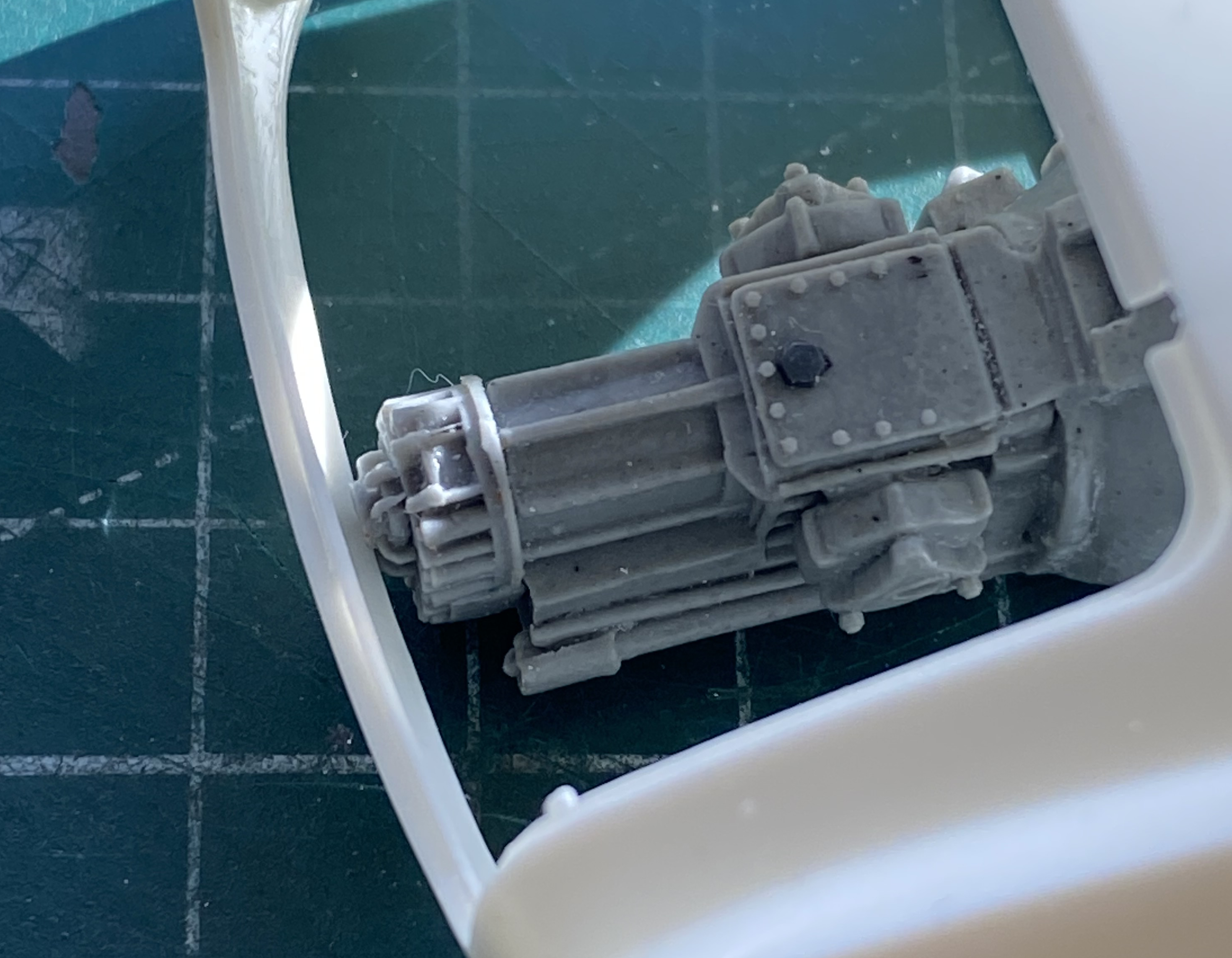
I used a flat file to true up the end of the block. I figured that I’d probably need an adapter plate to mate engine and transaxle. For that I used .040″ (1.016mm) styrene. I countersunk holes to match the bolt locations at the back of the block and stuffed tiny bolts into them and then glued the transaxle to it. I trimmed excess plastic away (and added some where I needed more):
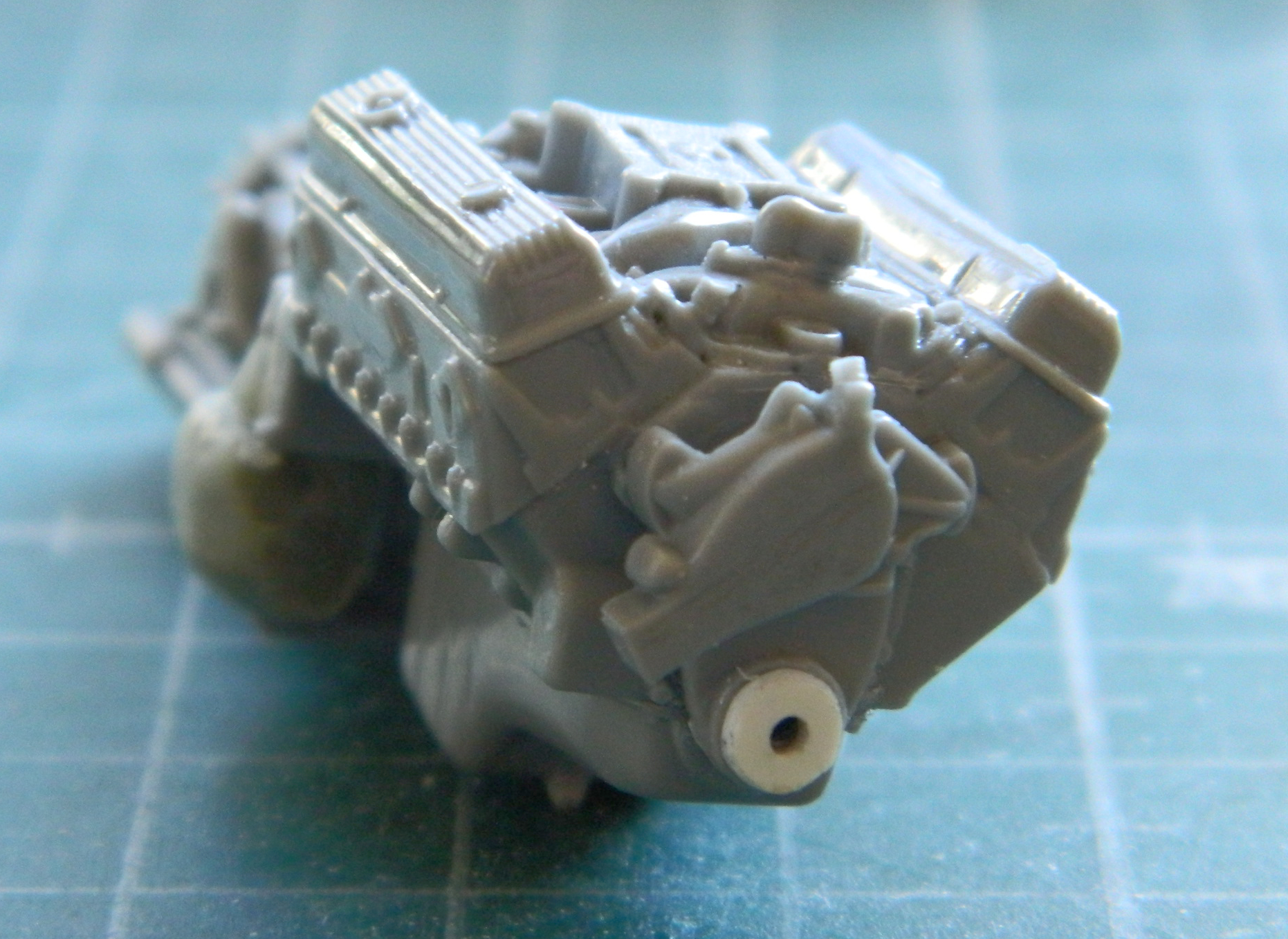
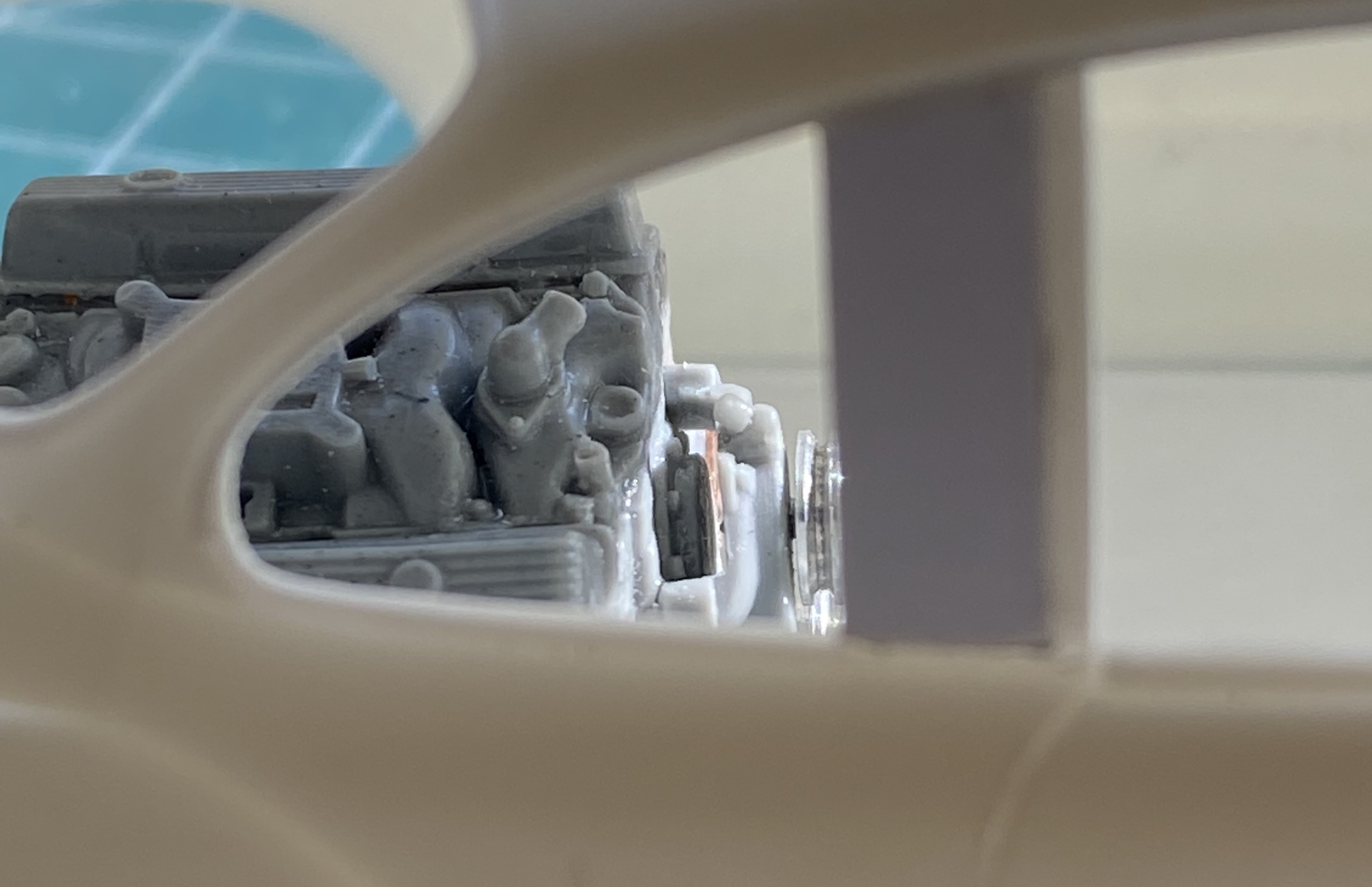
Since the location of the power train determines so much of what happens with this build, I was eager to see if I was going to have enough room for it:
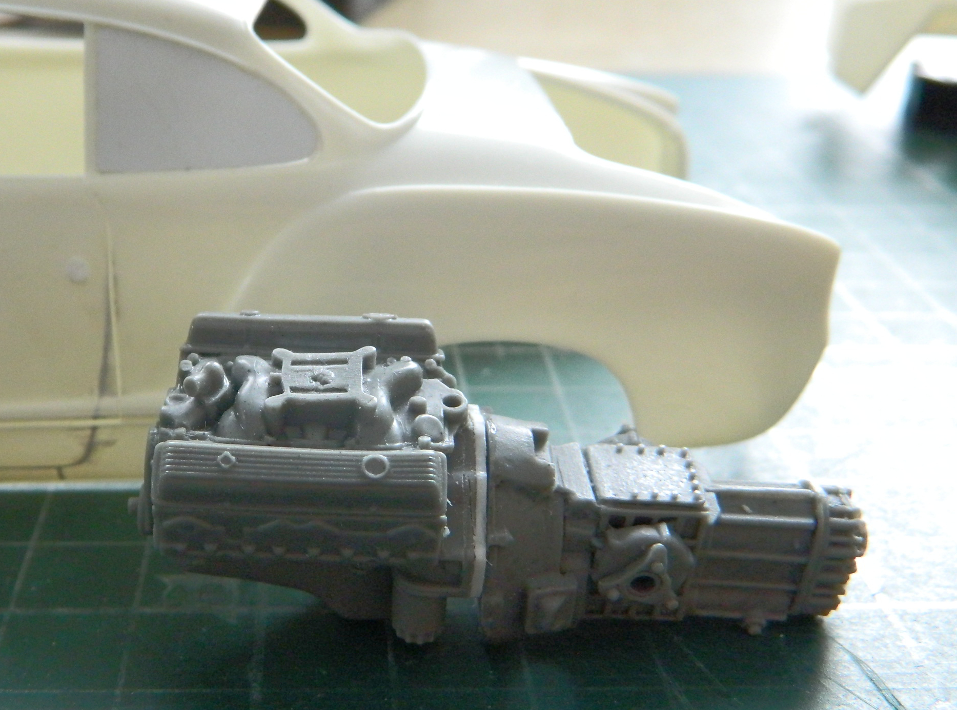
And it doesn’t look like it. Well, not unless I modify the body to fit it, and since there’s going to be a lot of body modifications anyway, I see this as another bucket of sand on the beach in terms of effort/work.
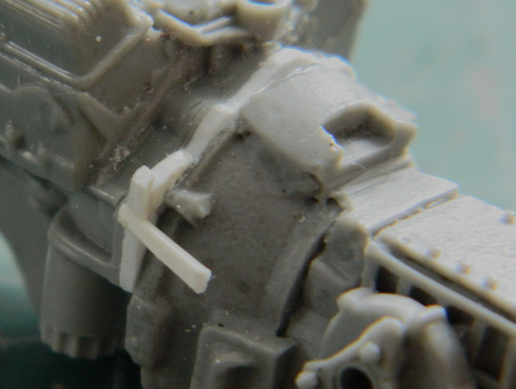
At the front of the engine and there a gap between the timing belt cover and front of the oil pan. I slid a bit of styrene scrap in and filled the odd gaps with superglue:
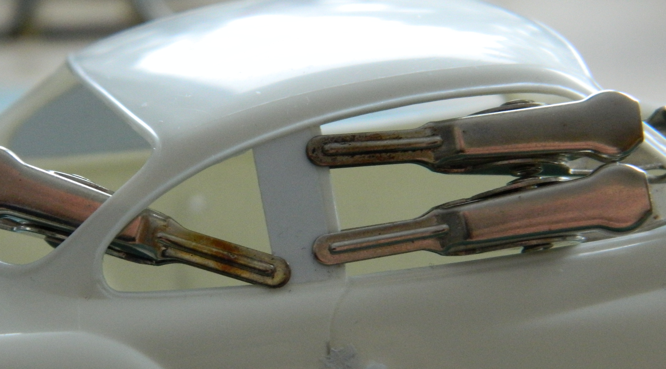
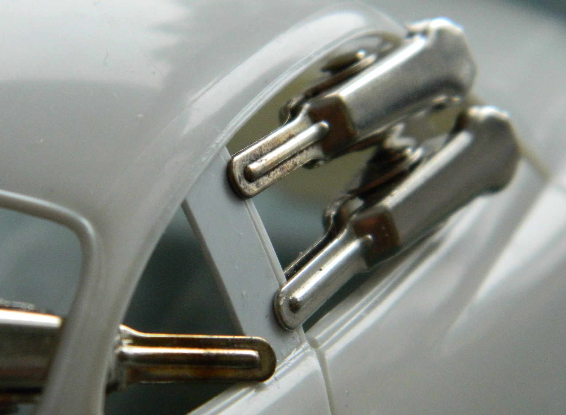
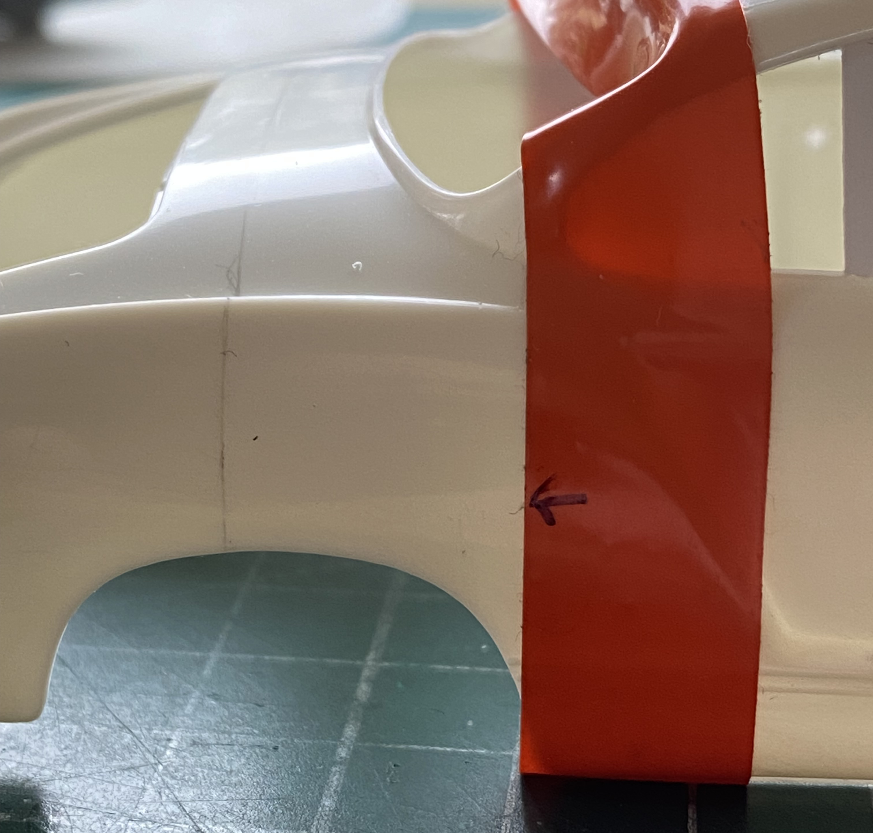
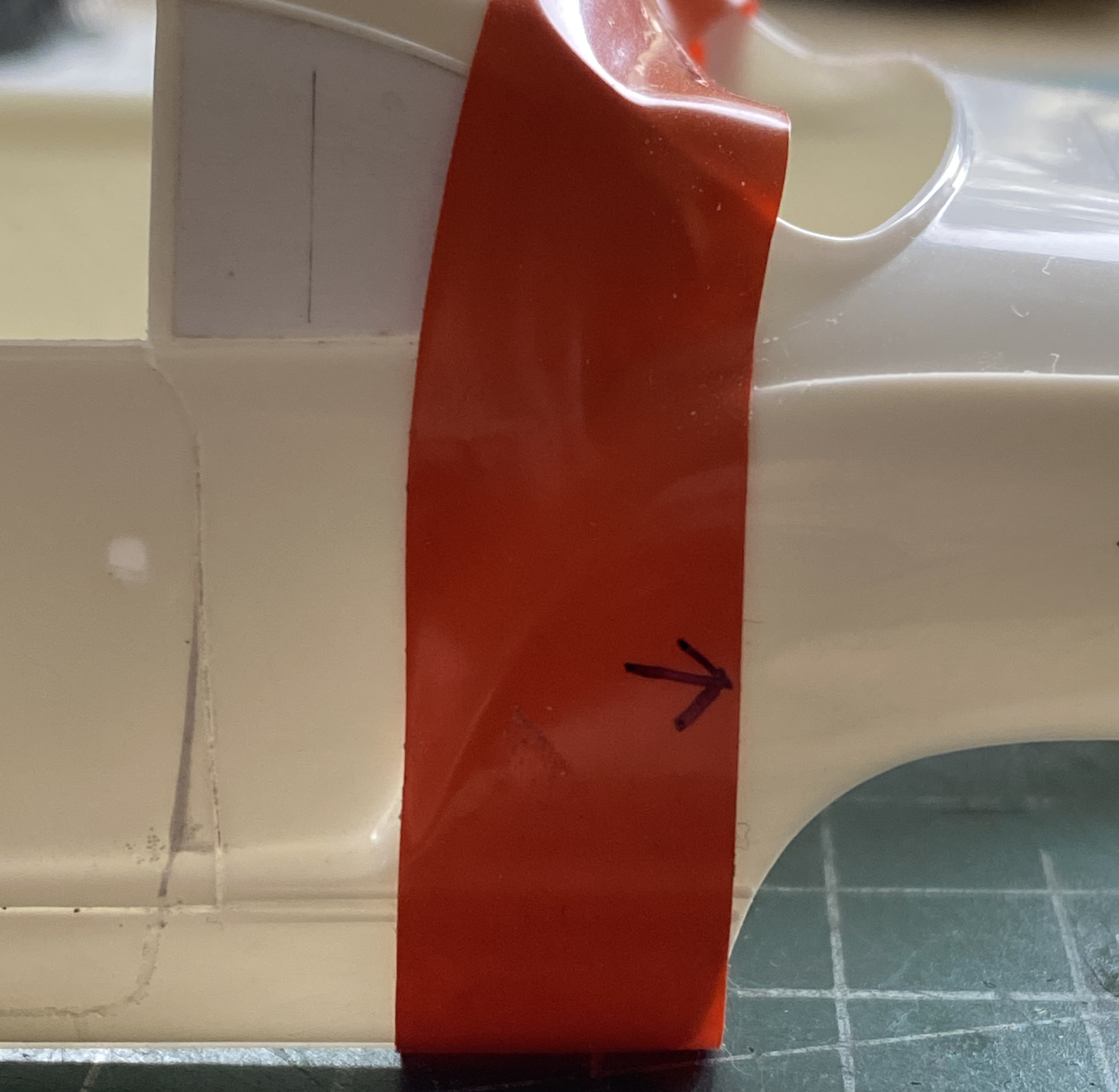
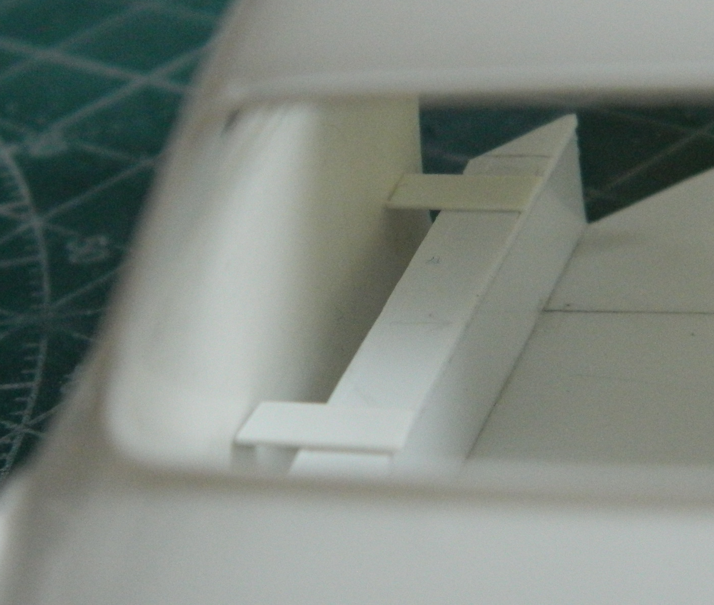
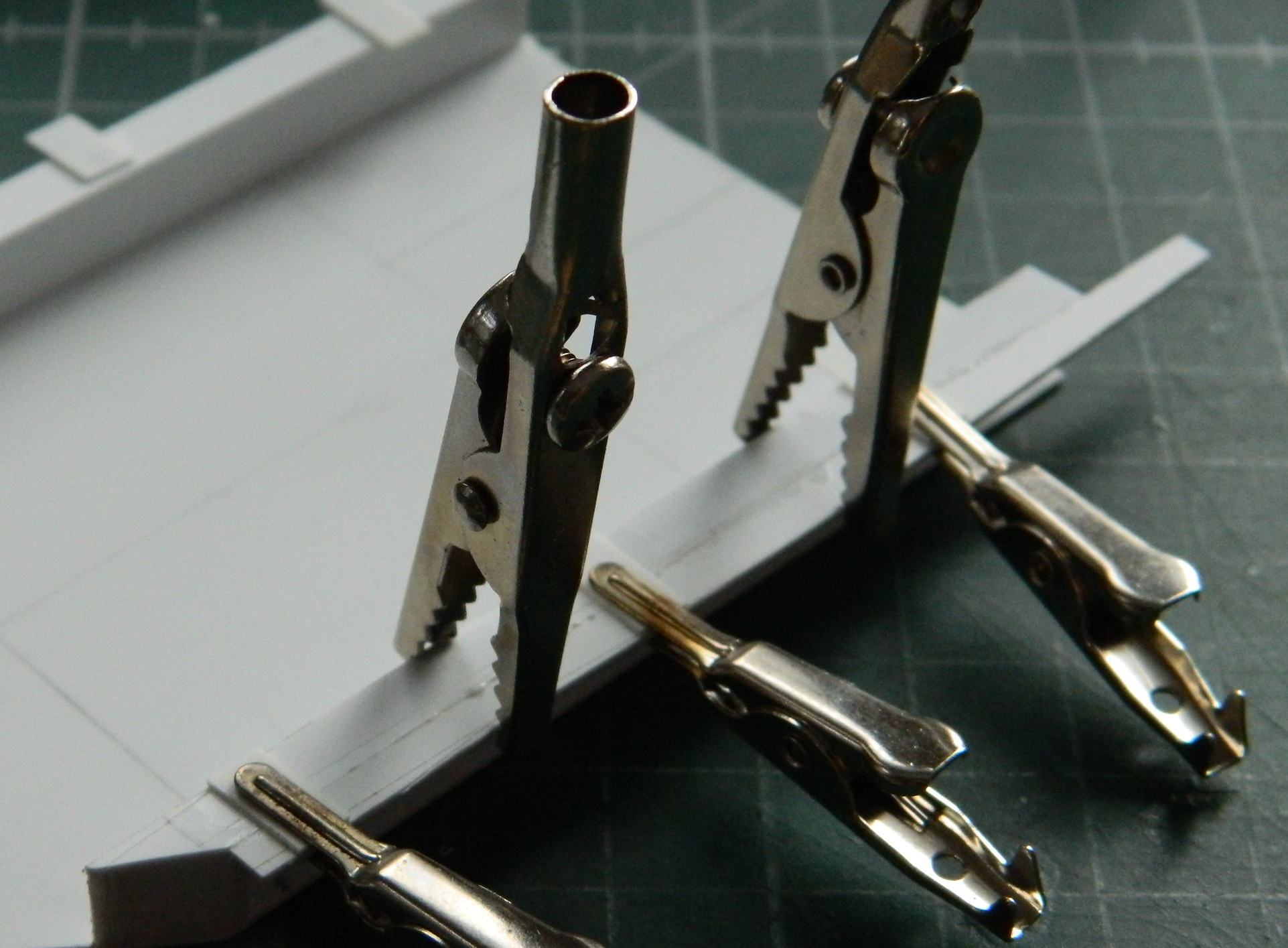
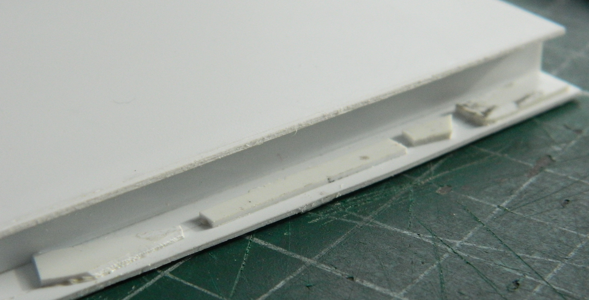
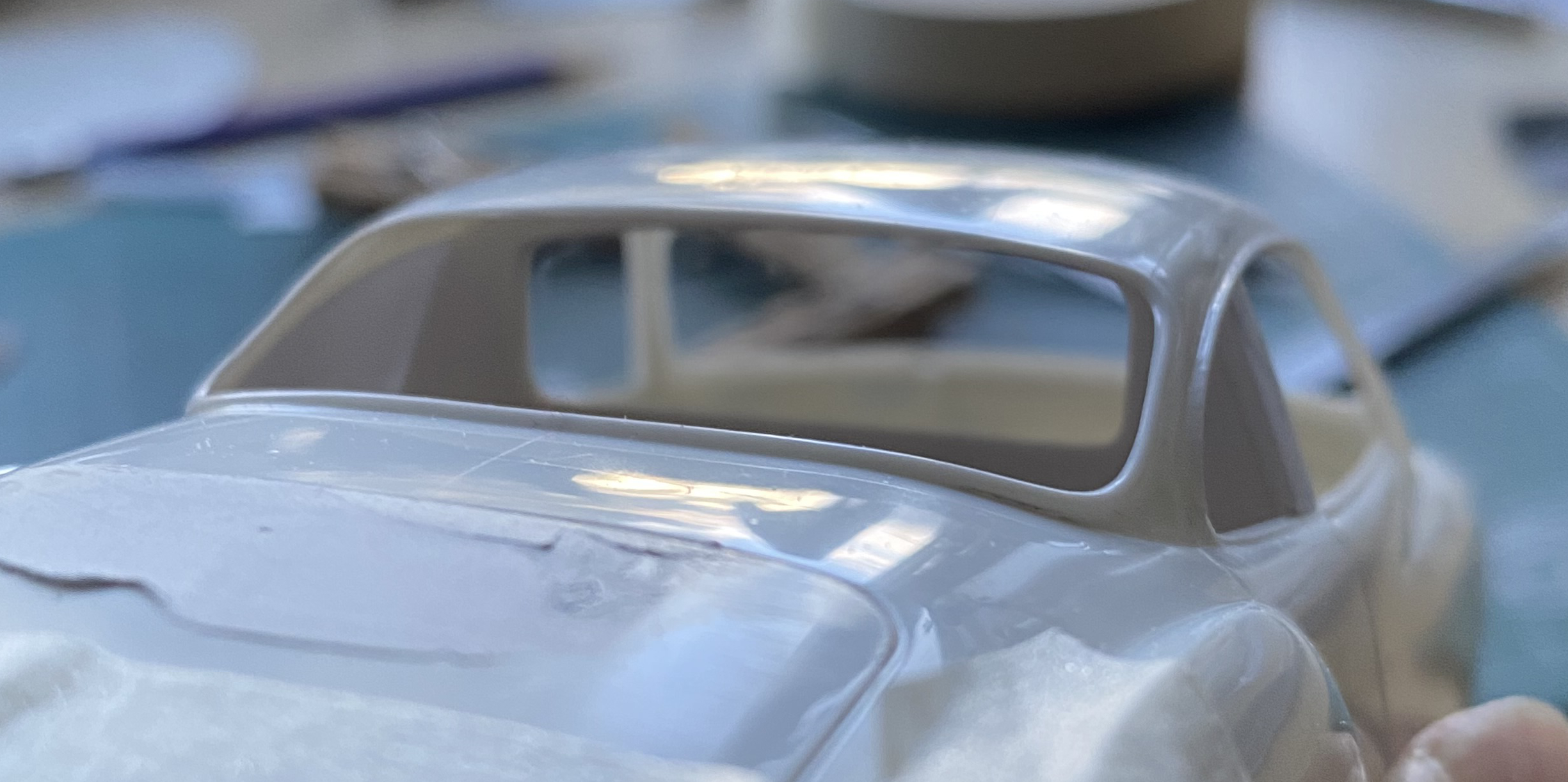
The rear of the body will be detached so that it can be opened. The B pillar is quite narrow. With the plug on the left side replacing the window, I know I’ll have enough to work with on that side. On the right side I had to add something large enough to split. I used .020″ (.508mm) for that, using flat-jawed alligator (toothless alligator?) clips to keep things aligned:
While the glue was curing, I added a disc to the front of the timing cover to provide the harmonic balancer that hadn’t been molded on:
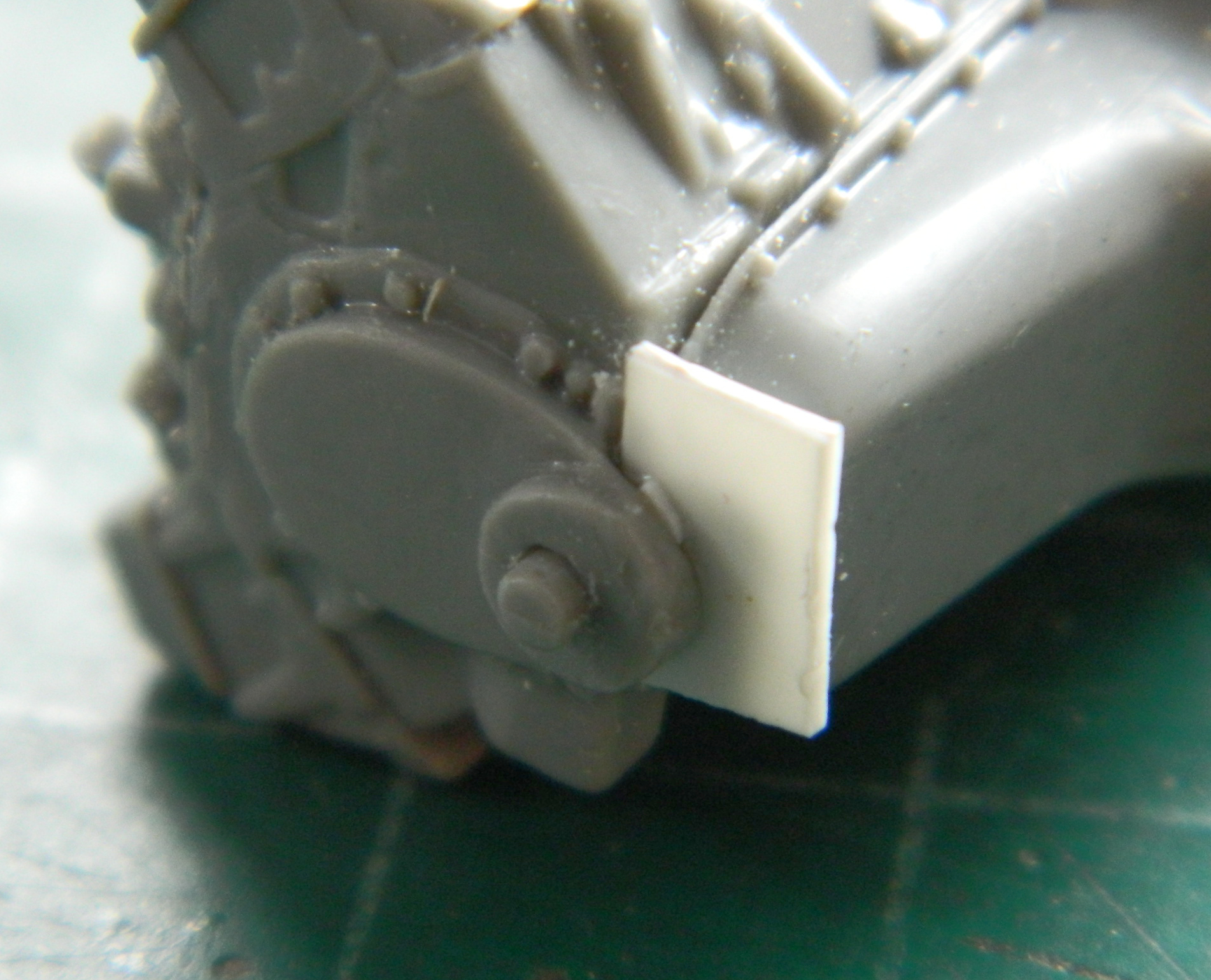
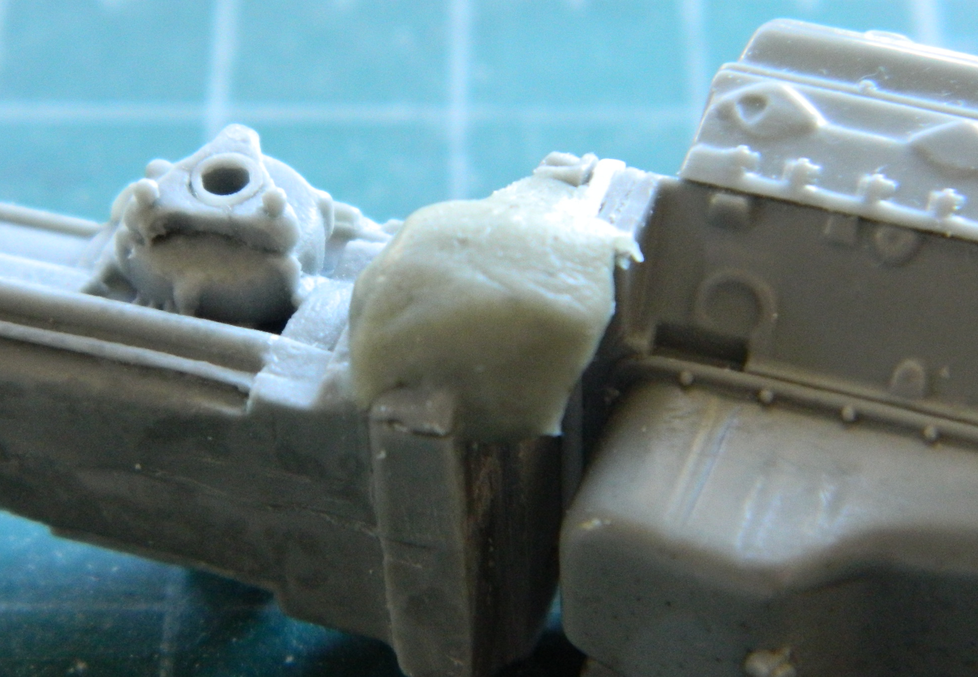
The bellhousing that’s attached to the ZF transaxle doesn’t have the provision to mount a Chevy starter motor. I built one from Aves Apoxie Sculpt…:
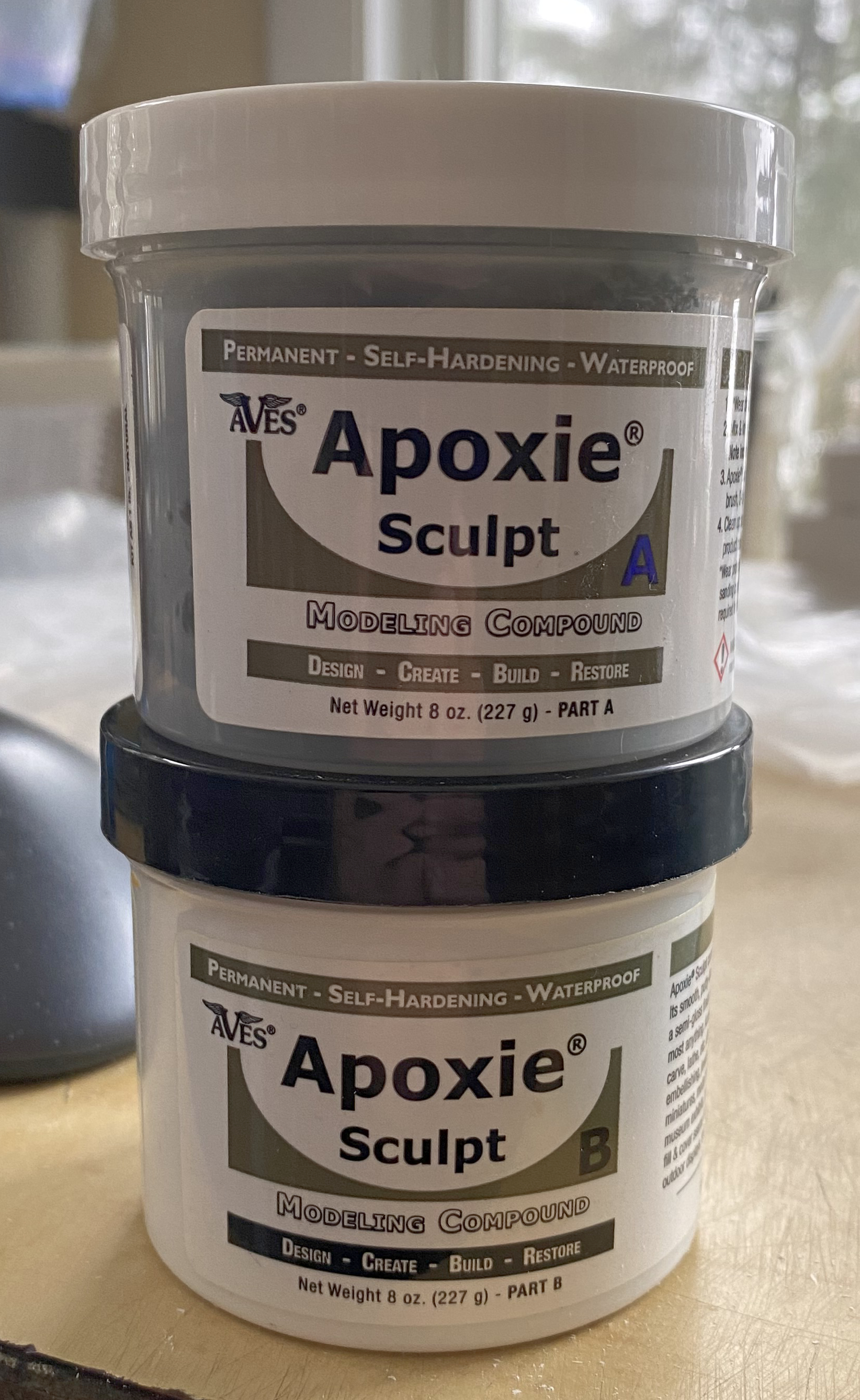
…and attached it to the bellhousing:
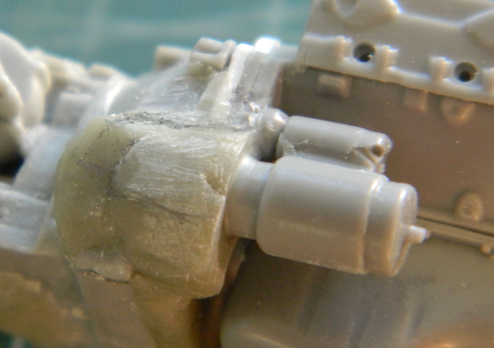
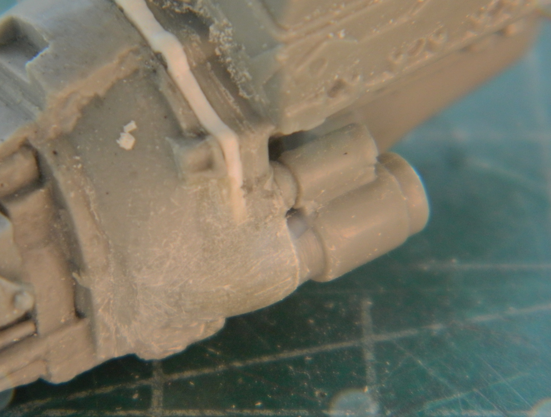
When I realized that I hadn’t quite added enough where I need it, I mixed up more and fixed that. (This material is very versatile and adding new material to already-cured material is no problem and it bonds well enough to be indistinguishable from the already-cured material…and yes…I plugged the bubble on the end of the solenoid.):

Continuing with the theme of a street-legal car used on the streets, I live in New York State. Summers can get quite roasting what with 90F-100F (32C-37.75C) days and relative humidity within the same range. Hot and sticky. At this point of the build, though I intend for the windows to be operable, I’m not entirely sure they will be. In order for this not to be a mobile over-powered bread oven, air-conditioning stops being optional. Because there is more than enough work to do yet, I went online to find an a/c compressor and the only one I found was unacceptable. That means I have to make one.
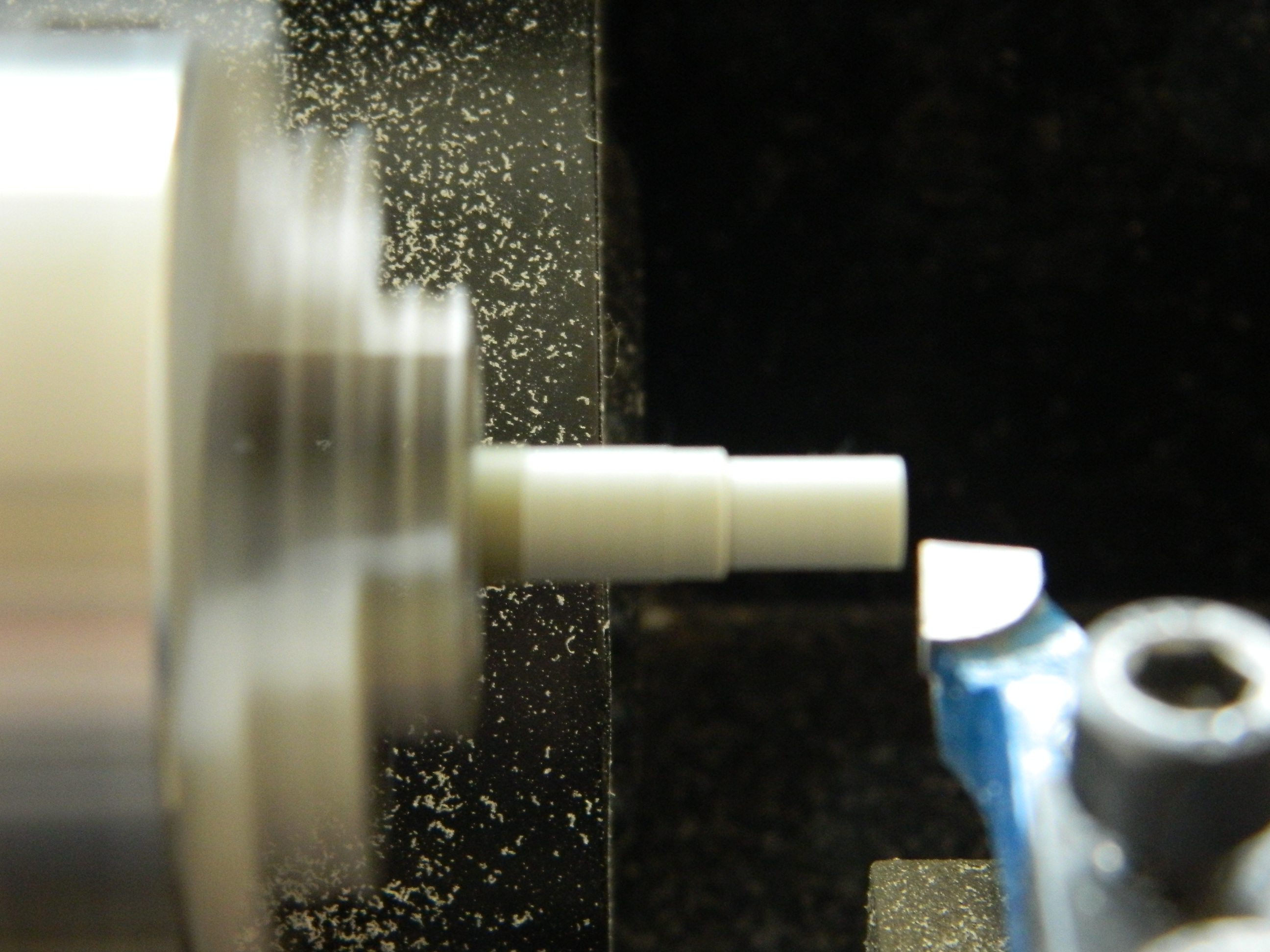
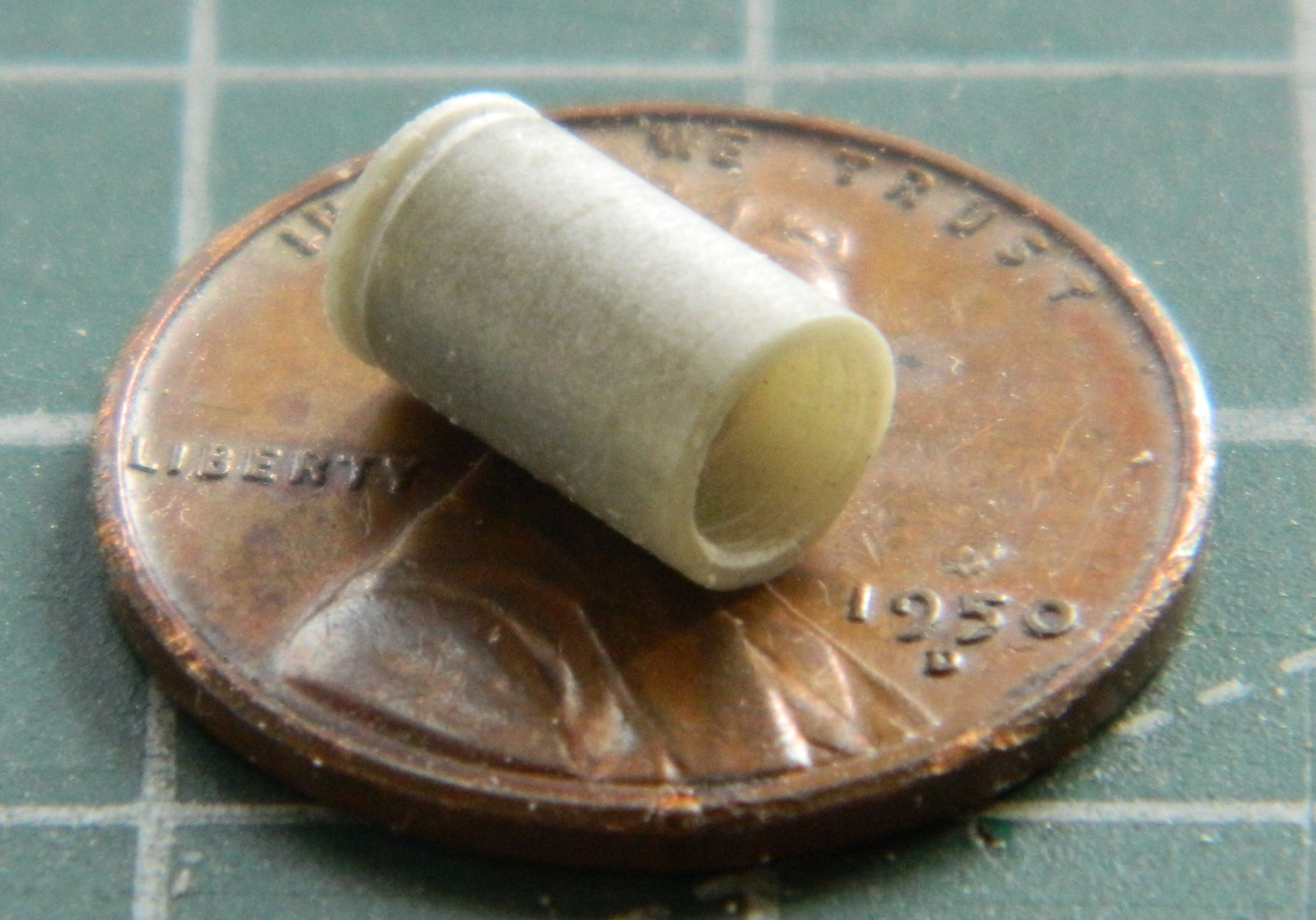
I have a few sets of AM pulleys and used one for the compressor. The only styrene tubing I have is either too little or too large. Once again I used Apoxie Sculpt. I mixed it (it’s a two-part compound mixed 50/50) and rolled out a rope of it. After it cured overnight, I took the straightest section of it, chucked it into my bench-top lathe, and turned it to match the pulley’s diameter and then drilled out on end of it to socket the back of the pulley into it:
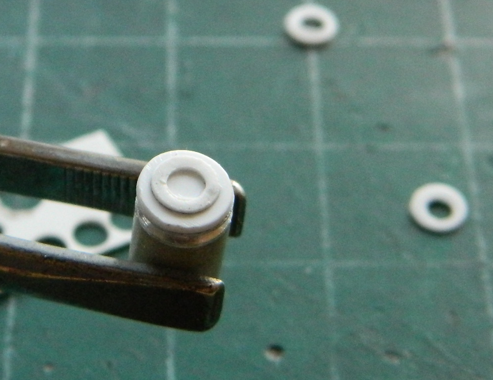
I punched a couple of discs from scrap using .020″ (.508mm) for the face detail and .010″ (.254mm) for the clutch face (getting the hole in the thin disc took a couple of tries to get correctly…punching the hole first, centering what will become the disc):
I made the mounts from .030″ (.762mm), making the required holes for the compressor and mounting bolts:
I failed to notice that the front mounts have longer lugs than the rear. Rather than redo the part, I added little scraps that I’d removed in error to it:

The last things I added were the wiring (two twisted strands of 40 gauge wire and sandwiched those between two pieces of .005″ (.127mm) scrap to replicate the connectors, a couple of small plastic bolt heads, and two resin nuts for the Freon line connections (sourced from resin AM bits of 1/35 scale bolts used to hold trunion caps onto suspension bogeys of a Sherman):
With the compressor built, I need a way to attach it to the engine. Generally, the compressor is attached to the upper left corner of the engine. Unsure as to whether or not that location would interfere with the exhaust headers I’ve yet to build, I decided to make a custom mount at the lower left of the engine and for that I need mounting brackets. Detail Master makes a number of nice PE bits:
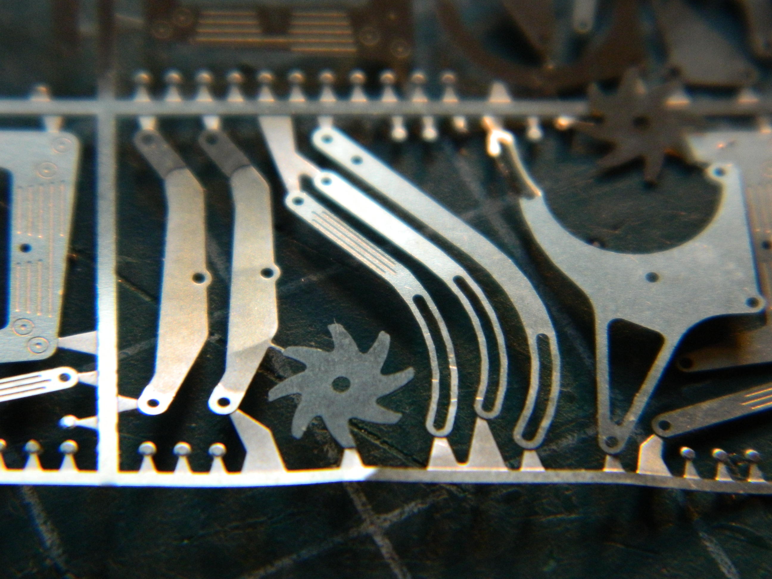
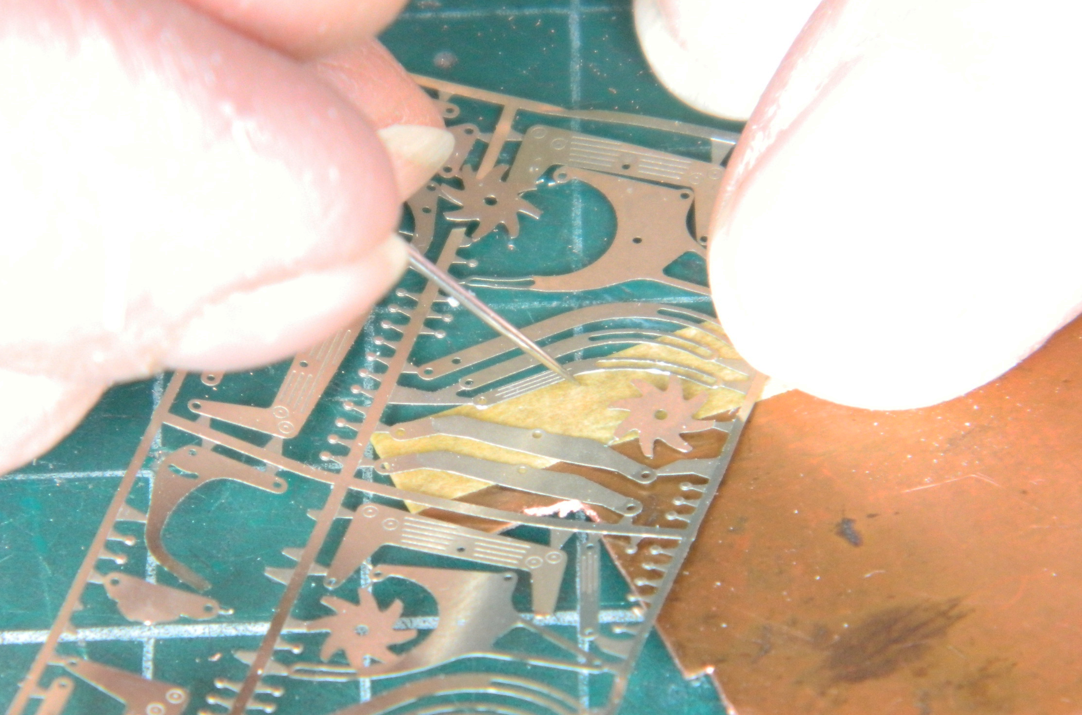
The problem with these parts is the Detail Master parts are only .003″ (.076mm) thick. Funny. I used the word “thick” because they are not thick at all and turned out to be far too flimsy to use. Instead I decided to trace them onto .005″ (.127mm) copper shim stock. My first try, as is typical for me, went well (I used hemostats as a clamp so that I could use a needle to trace the part):

Also typical for me, the next couple of attempts were horribly unusable. Rather than keep trying the same method, I used Tamiya masking tape to trace onto instead of the copper. That worked better and, after filing/sanding (no pictures of which I’d taken), ended up with something I could use:

I used a really tiny bit to drill holes and then cut away the material between the holes to get a slot:
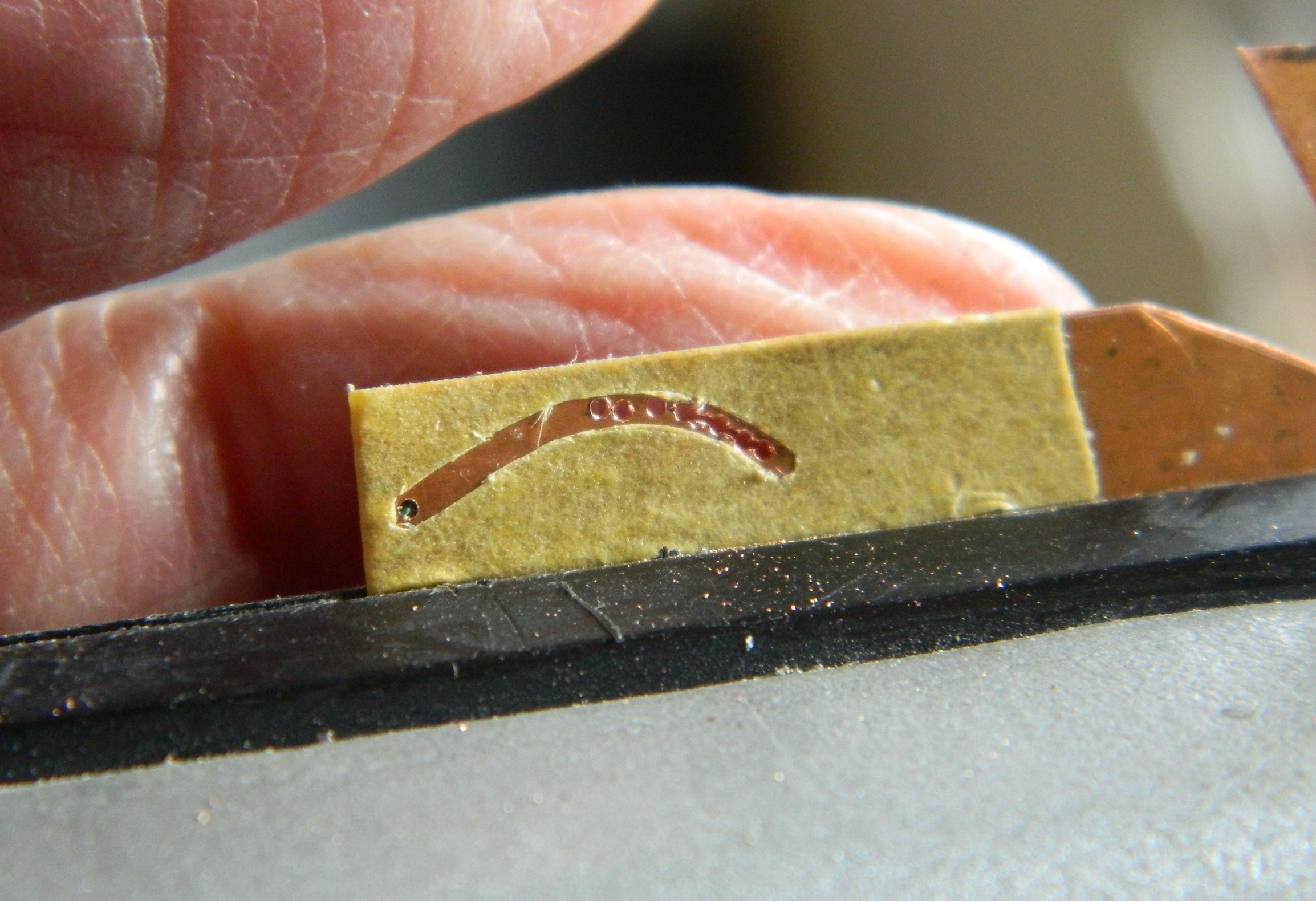
Well…something slot-ish. Copper is a relatively soft metal. I bent back the shape to expose the serrated edge inside the curve and filed/sanded it smooth. That worked well enough to do the same thing with the outside of the curve:

Yes, it’s a little bit thick but subsequent filing/sanding thinned it out more correctly:

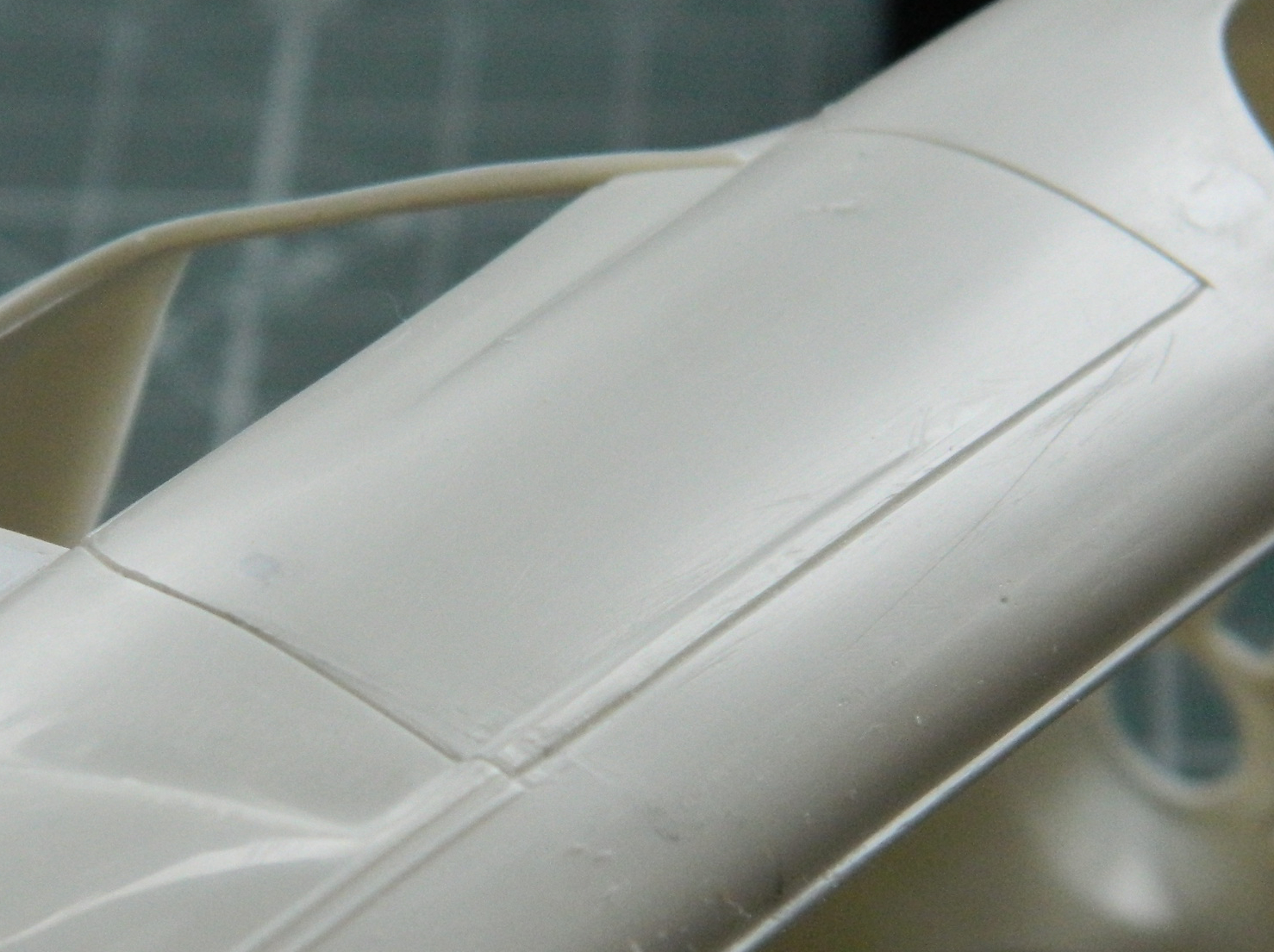
Needing a break from SODDING SMALL PARTS, I turned my efforts back to the body (unlike the decrepit wreck I inhabit). For whatever reason, the 3M Acrylic Putty was flat-spotted after sanding…like all over the place. None of the photos I took really show the problem well, this is the best of the lot:

I used a scriber to scrape all the putty out and redid the unneeded panel lines with stretched sprue:

And in this photo, I filled a poorly scribed line while I was gluing sprue down:


That seems to have worked better (later on a coat of medium gray will reveal if I’d been successful):
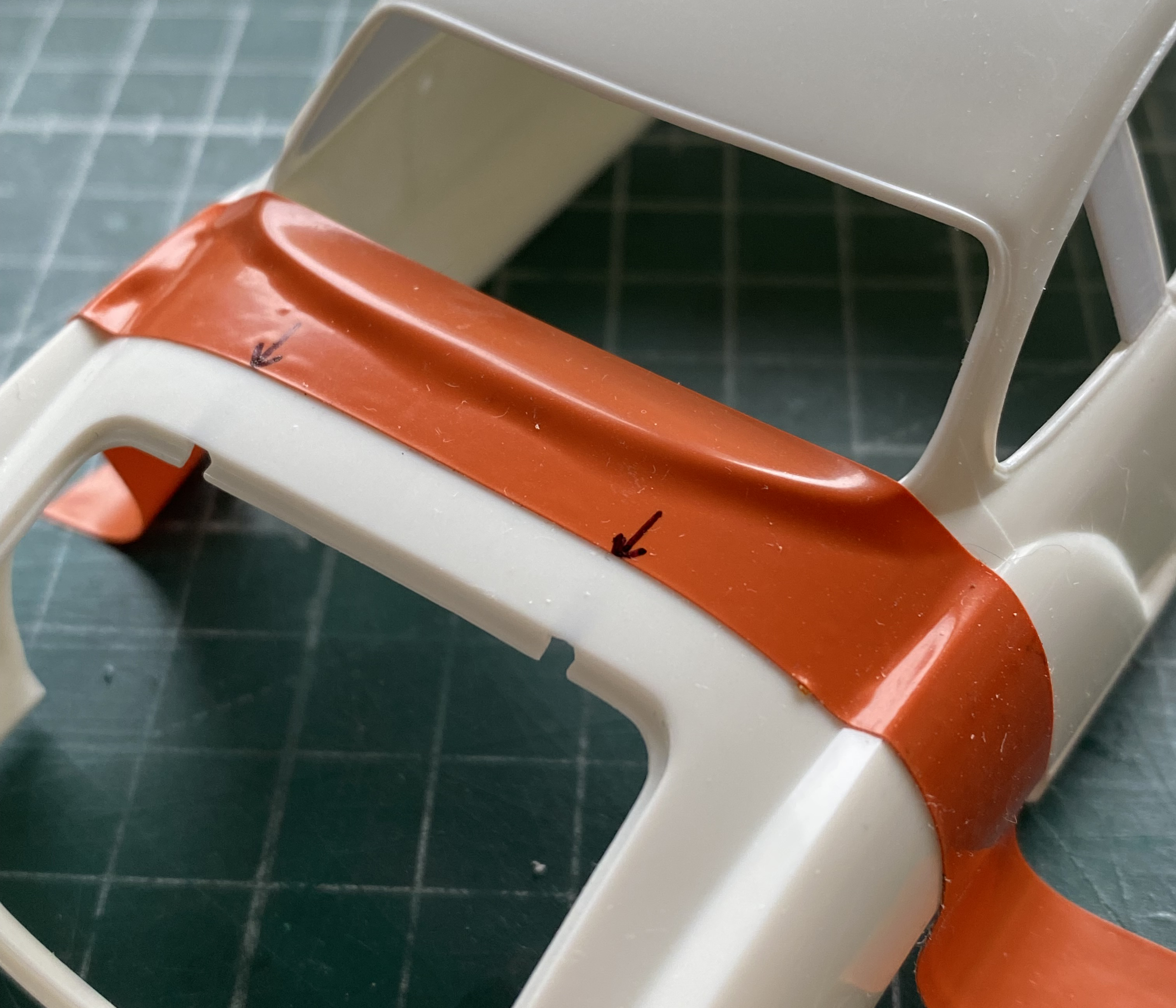
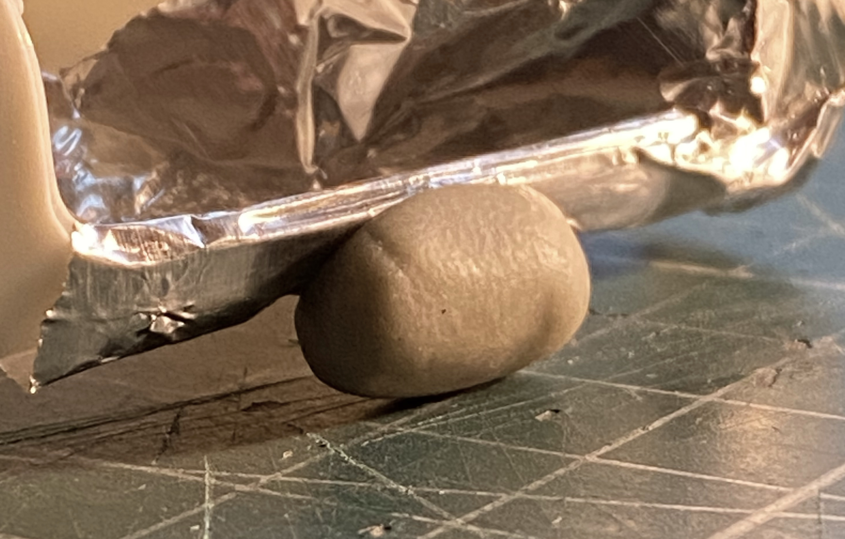
And completely by chance (because I wasn’t really checking for it), I discovered that the body is twisted and doesn’t sit flat. Everywhere else on the body is in contact with the cutting mat except this area:

I tried a hairdrier on high setting. I tried boiling water. Nothing worked. Then I decided to use a mode that’s worked for (and too often against) me over the decades. BFMI. Brute Force and Massive Ignorance. I grabbed the body and just TWISTED IT. It took a few attempts but now it sits flat and didn’t break:

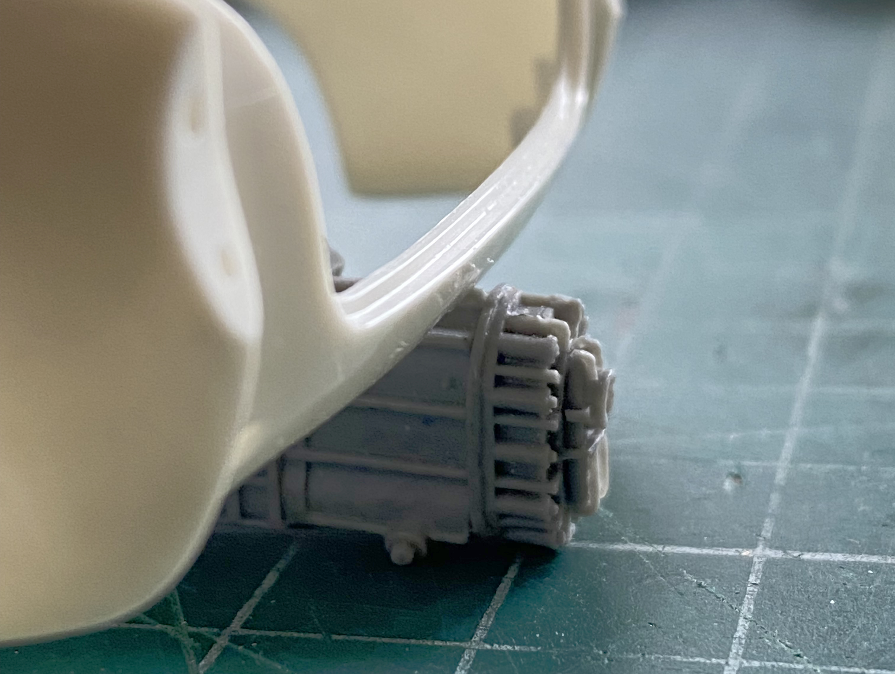
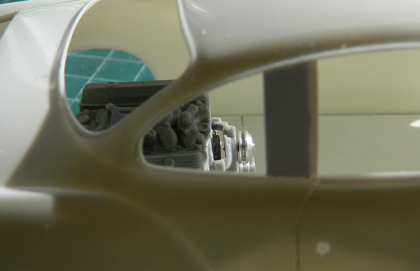
With the water pump and pulleys on the engine, now that I know what real estate is needed, I did a closer inspection of engine placement. With the power train at its furthest rearward point, it sits too far forward:
In order for the front of the engine to be back far enough to where I want it to be, a bit of the transaxle sticks out of the back:

So not only will the rear wheel openings need to be moved, I was thinking that the whole body would need to be stretched. I started playing around with that notion, laying out lines that I thought would involve the least amount of work:
Note that I’m not concerned at all about having to move the wheel wells. I’m going to be adding fender flares so those areas are going to be reworked anyway. I just don’t want the rear of the transaxle flapping out in the breeze. I could have added lots more pictures of the various notions I investigated (Mssr. Goldberg would have been awestruck). Each “solution” created more problems, none of which was I remotely interested in dealing with. I pulled the tape off and went to bed.
When I awoke (and properly, necessarily, caffeinated), I found myself wondering if I’d been a German engineer in my previous life. I don’t need to stretch the whole back of the body. And I didn’t want to stretch the whole back of the body. It wasn’t because of the amount of work that would require. If that bothered me, I wouldn’t be doing this. What I wanted was a way for the curves to move smoothly from the rear of the back window to the rear of the car…and I couldn’t see how to do it. What I needed was a way to cover the rear transaxle. Just that.
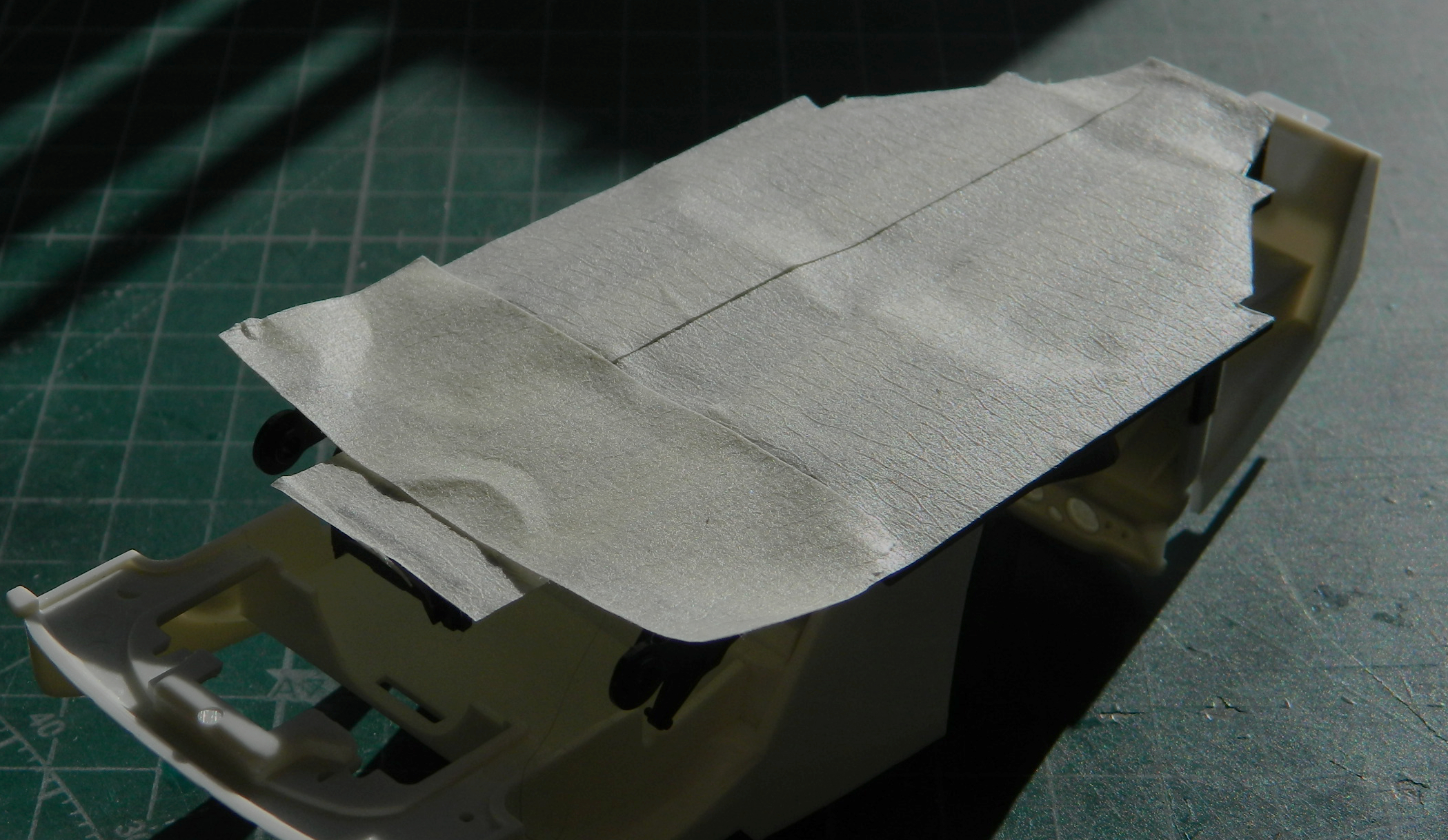
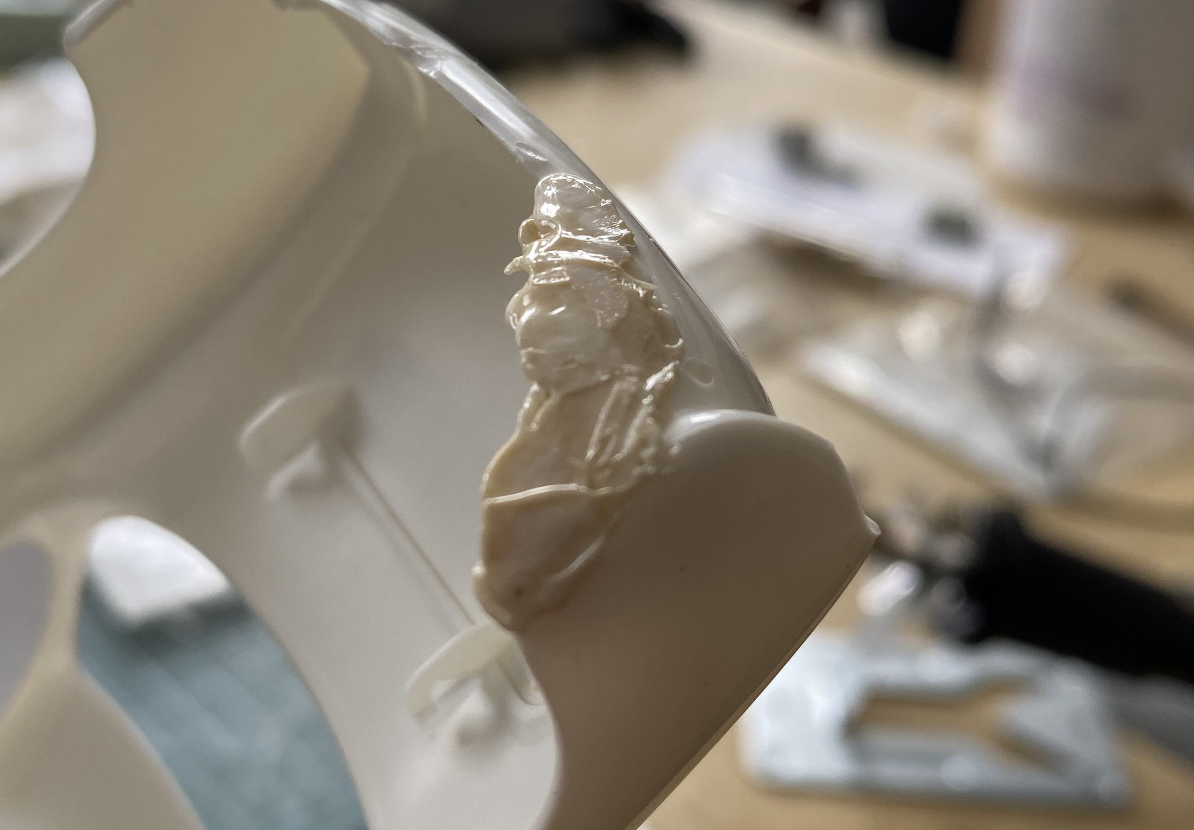
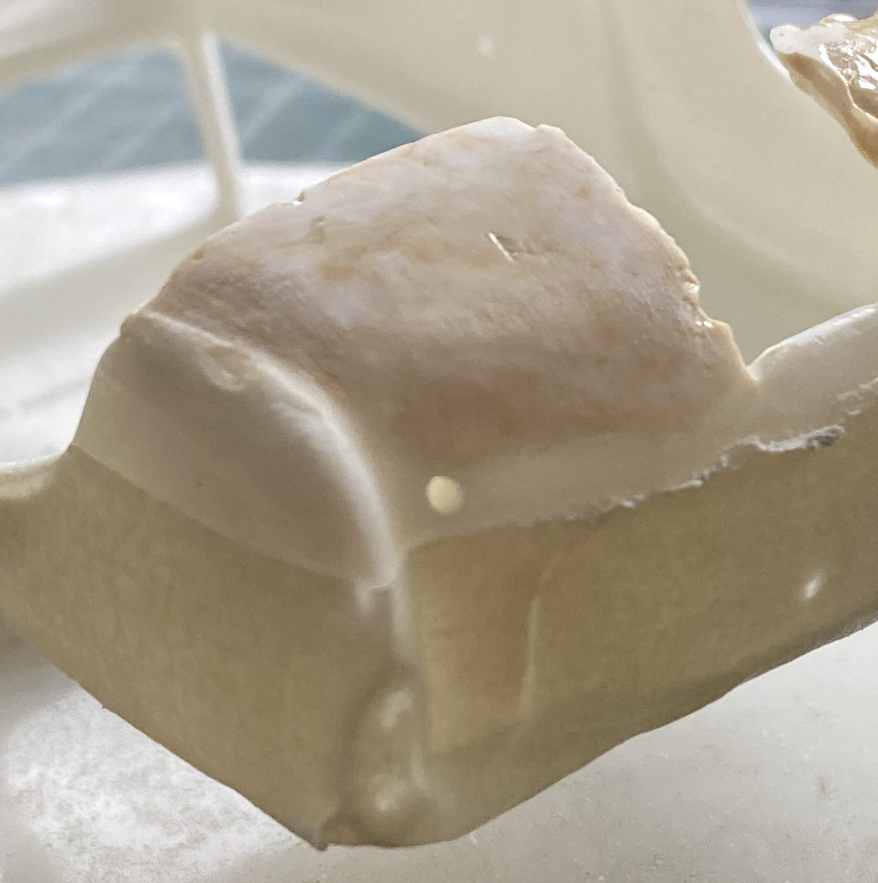
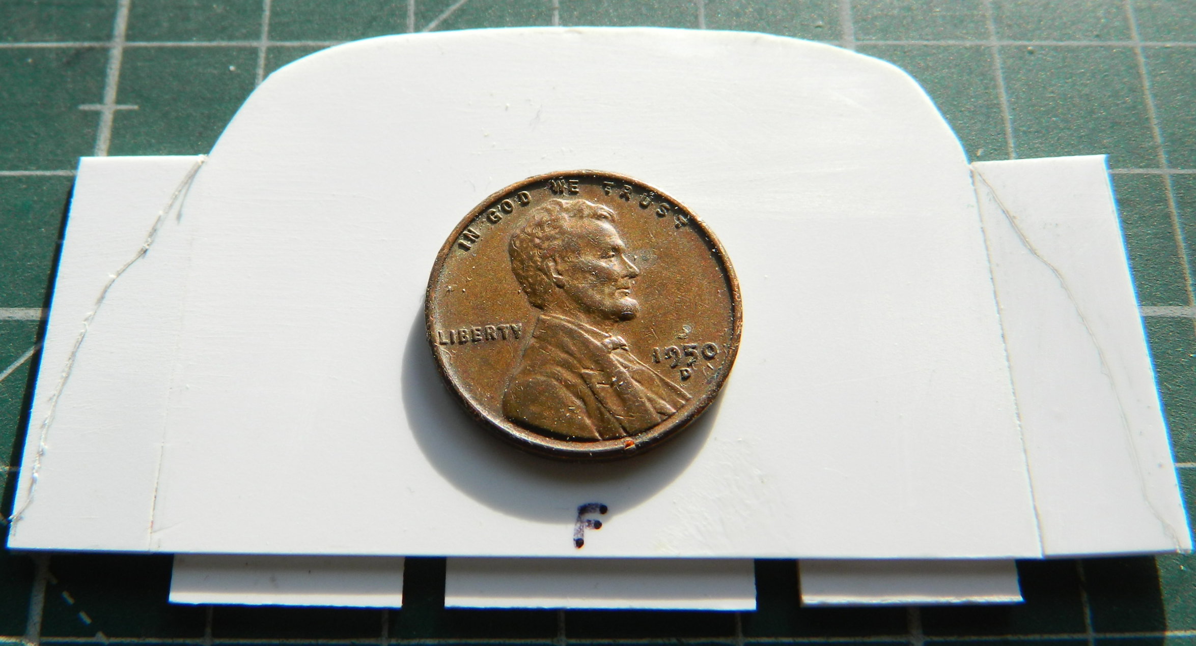
My first thought (in a German engineer sort of way) was to use the epoxy putty to form a buck and then vacuform a cover (I put aluminum foil over the body to keep the putty from bonding to it):
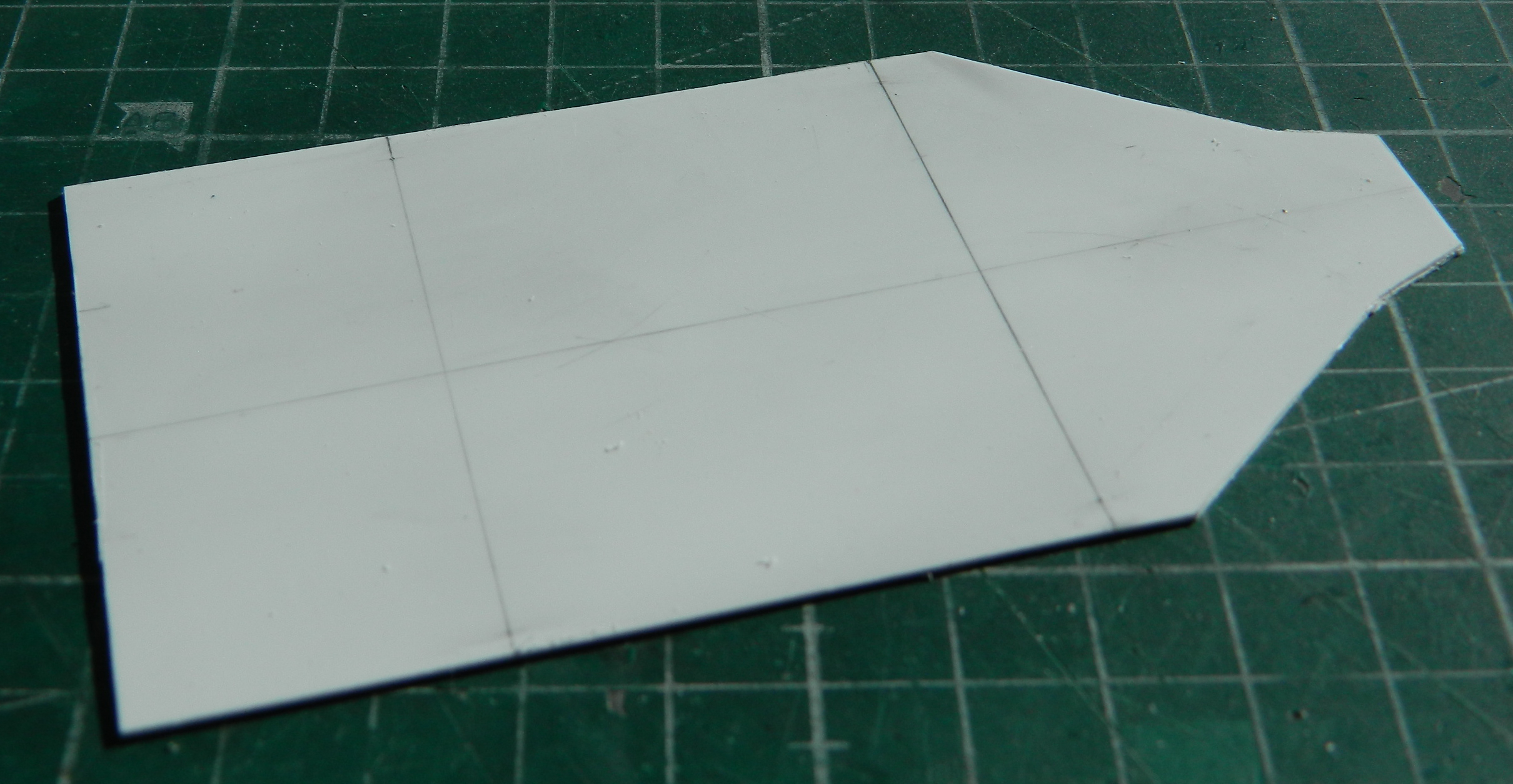
While that was curing, I started working on the belly pan, which is what would form the floor of a semi-monocoque frame. My first attempt was to just trace the kit’s belly-pan onto a sheet of .030″ (.762mm) styrene. I thought that would fit but it didn’t. I spent far longer than I should have on making it fit (chasing pencil lines across the styrene, erasing, doing it again, erasing it again) until I realized that it just wasn’t working. I checked the fit of the kit’s belly-pan again and it fit. Okay, that means that I’m somehow screwing up the tracing process. I covered the belly-pan with masking tape, trimmed it, and took the tape template from the belly-pan and placed it onto the styrene, cutting around the tape with a scriber:

That was the starting point. It seemed that nothing was really square. But since I had the basic dimensions, I erased, measured, squared, erased some more, until finally I had something that didn’t contradict itself visually:
I dropped the body over the pan and checked the powertrain placement again. To get the engine placement where I want it, I am indeed going to have to deal with the transaxle fitment problem:
I’ll bridge that cross when I get to it…
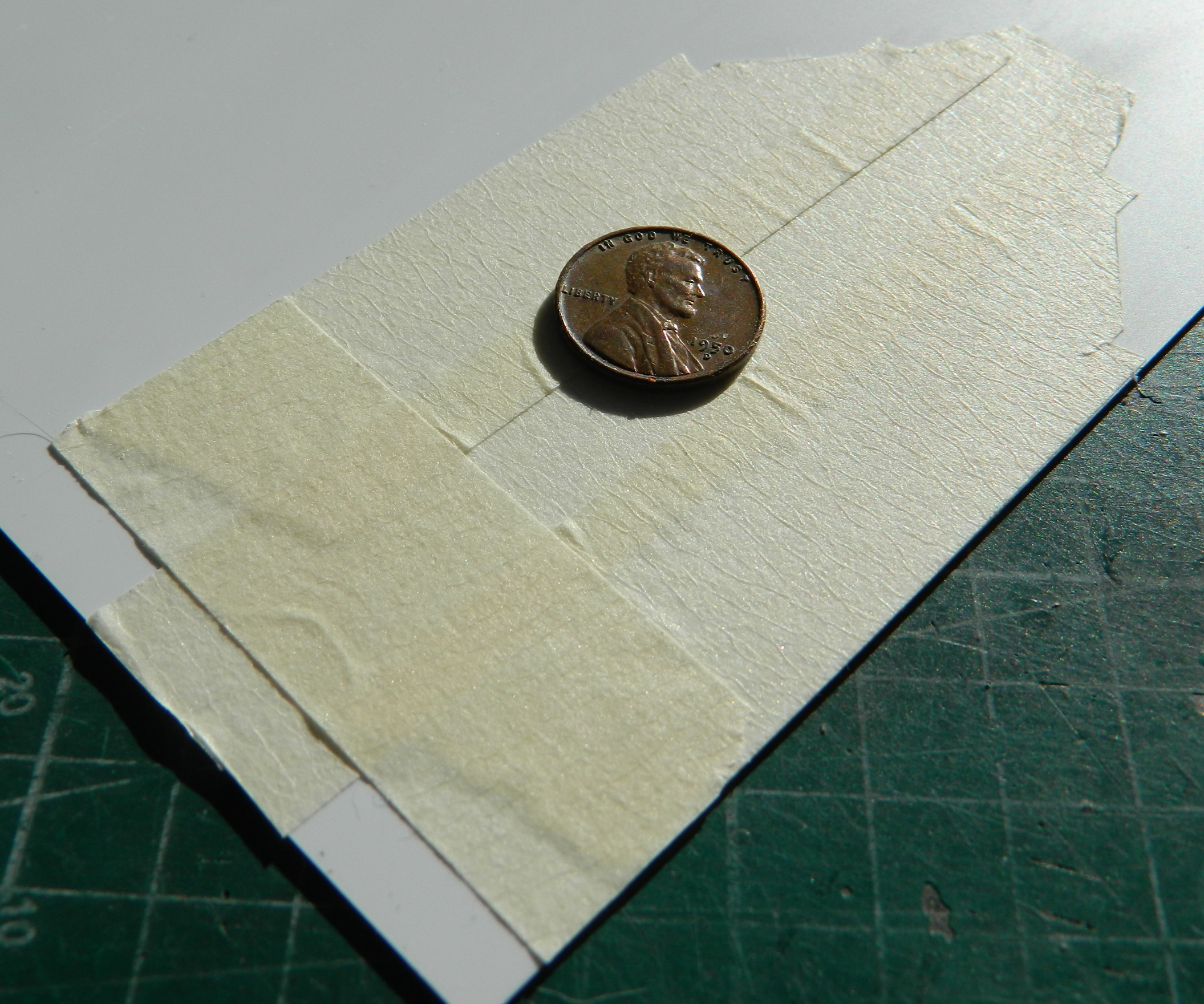
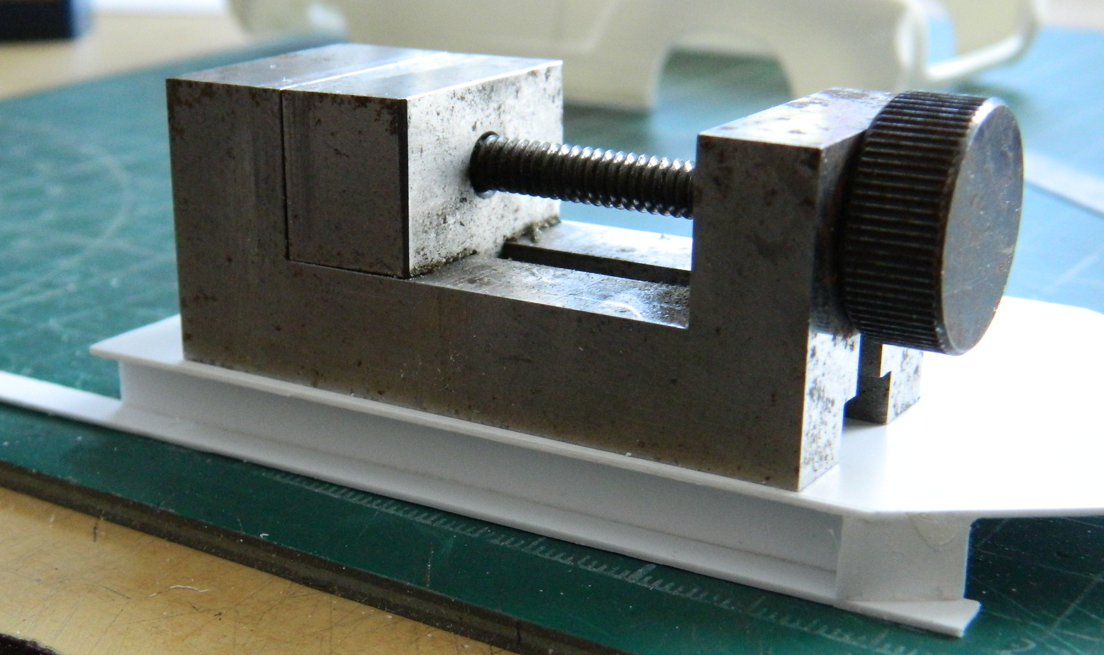
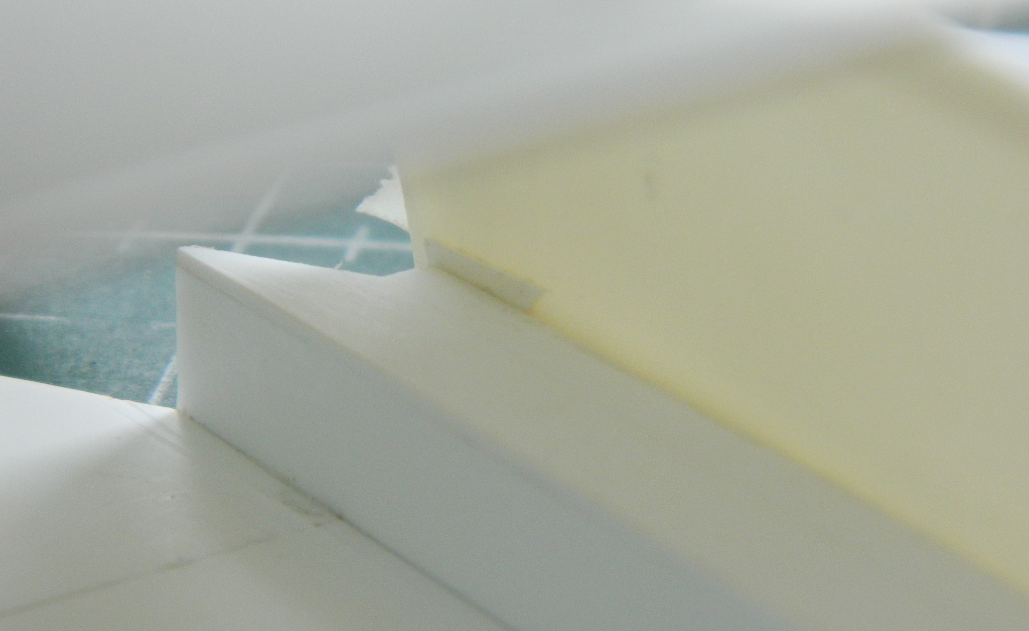
The reason I moved the bottoms of the doors upward was to have a space for sponson-mounted fuel cells. Best I get started on them. I used a milling vise as my 90-degree angle and used .030″ (.762mm) for the sides of them, using the lower edges of the doors as my gauge, the height of these are about 1mm below the opening:
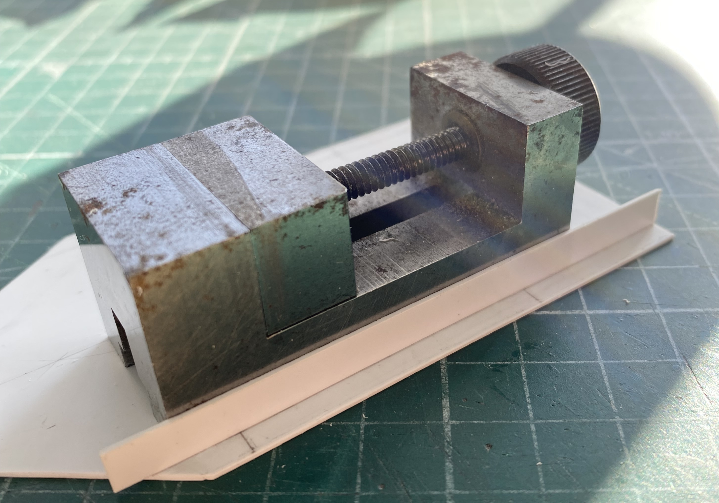
Then I used the vise as a weight to hold the tops down firmly:
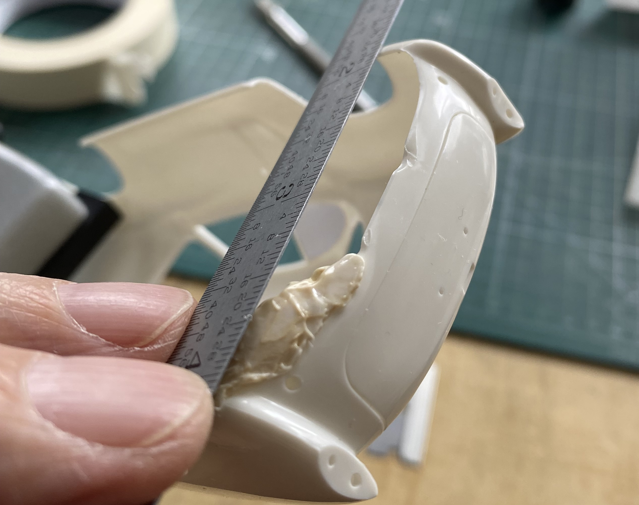
While those were setting up, I put the rear tires (resin parts from HRM, the same source for the ZF transaxle) roughly where they go longitudinally to get a very rough approximation of what I’d need from the fender flares:
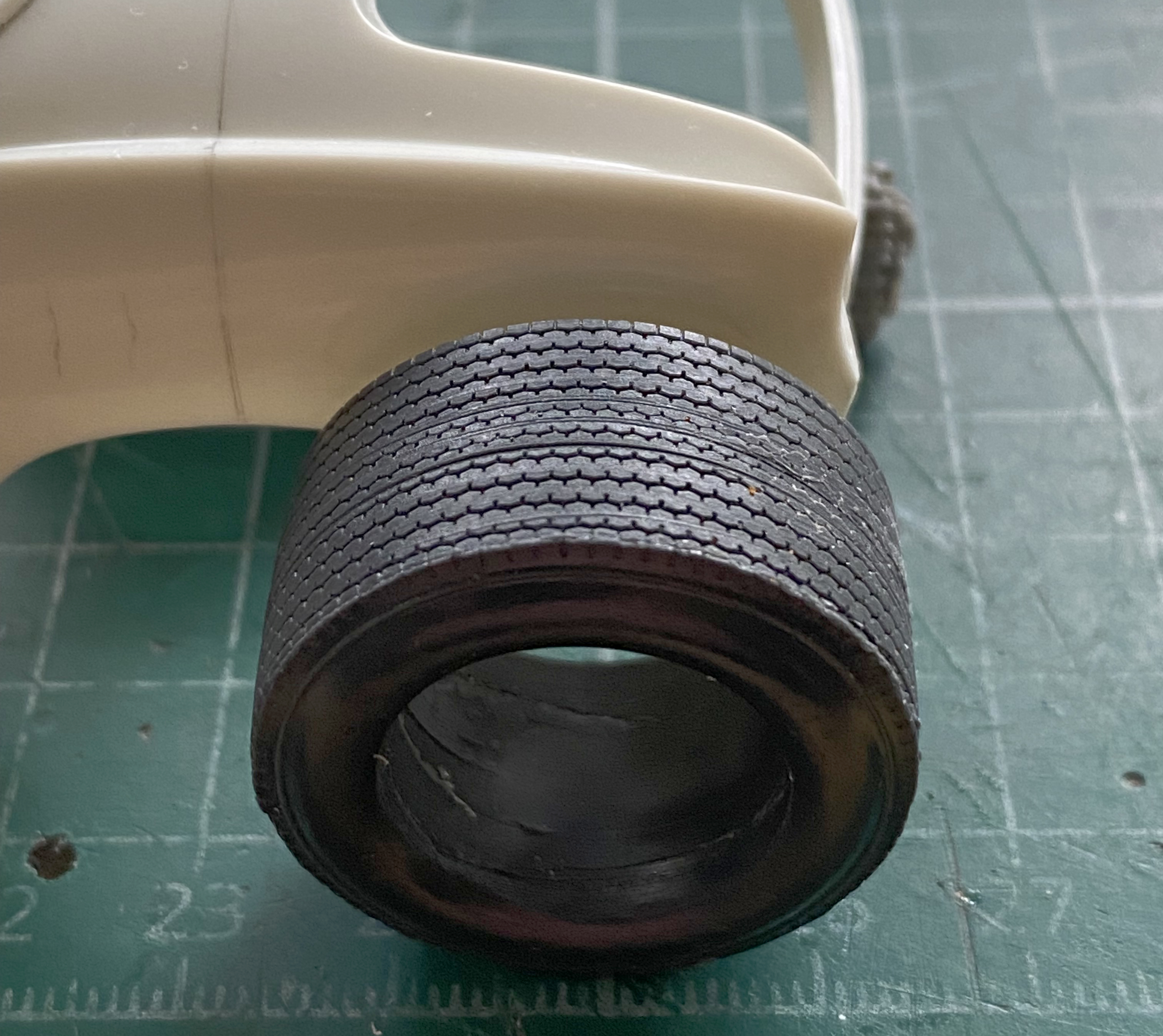
It’s looking like about half that tire will stick out beyond the body. Also note how far back from the stock wheel opening it sits. And there is going to be substantial reshaping of the back of the car to accommodate it all. For fender flares, I’m going to use highly modified VW Bug fenders. Because of the taper to the rear of the rear Bug fenders, I’m going to put those on the front and connect them under the nose of the body and create the “cow-catcher” front spoiler so common at the time (and yes…I bought a VW Bug kit just to get the fenders):

I’m going to use the Bug’s front fenders on the rear:

Because of the amount of work and reshaping required, I’m waiting until I have the fenders fit and attached before I reconsider what I want to do about the transaxle sticking out. And because of the prominent headlight buckets, I’m going to transform those into the taillights. At some point I’m going to have to decide where I want the air that is sucked into…wait…did I tell you about the radiators? Now wouldn’t be a bad time to do that.
I’m not putting the radiators in front. I’m going to reshape the forward portions of the rear fender flares into scoops. Air inlets. Behind those inlets will be the radiators, which is why I’m discussing the radiators in plural. Racing cars that have front-mounted radiators have to deal with the volume of air introduced INto the car in some manner. The GT40s (and more than one of the 60s and 70s F1 cars) had two triangular-shaped outlets on top of the nose of the car with ducts to allow the introduction of all that air some way out. Air that comes in needs someplace to get out, otherwise odd and unwanted things happen when, and where, all that air gets compressed. A front-engined, front-radiated, car will start to get light in the nose at very high speeds because the air has no easy egress. It stuffs the engine compartment, meets the firewall, and gets out at the base of that firewall. The high-pressure air can get so high-pressured that it starts to lift the nose of the car. As it lifts the nose, the simple downforce created by the weight of the car is lessened and the nose rises. This allows more air under the car and, in addition to the air being stuffed into the engine compartment, the air allowed under the car as the nose punches through it lifts the nose even further. From the throttle-jockey’s perceptions, steering authority degrades into steering requests. Not pro-survival when the speed of the car is into triple digits and not merely because there aren’t tires on the roof.
Putting the radiators towards the rear of the car mitigates the lifting effect of all the above. But the air still needs to get out. It will find a way out, but with a car possessing a full belly-pan, lots of drag is the result because the air can’t simply force its way out from under the body. If you notice Group 7 cars from the 60s and 70s, almost all of them (including the GT40s) had screen panels at the rear so that the air has SOMEplace else to go and an easier way to get there.
There. Now I’ve mentioned the radiators. It’s not unlikely I’ll mention them again later on.
Now that the basic structure of the sponson tanks has been blocked in, I have to get them to fit the inside of the body. I did it by placing the body over the monocoque and gluing (lightly, I mistakenly thought) blocks to the top of the sponsons and up against the body:
Then I added strips of .030″ (.762mm) to that width:
Once that glue cured, I added scraps of the same thickness under the seam. These extensions are wider than the bottom of the body and with the many, many, on-and-offs ahead for dry-fitting, I’d really rather that they didn’t snap off:
While those were curing (both sides), I used the scriber and razor saw to remove the Bug fenders. Curious being that I am, I wanted to get a notion as to how much work was going to be needed to get these to go from detached fenders to solidly attached fender flares. In short…LOTS:
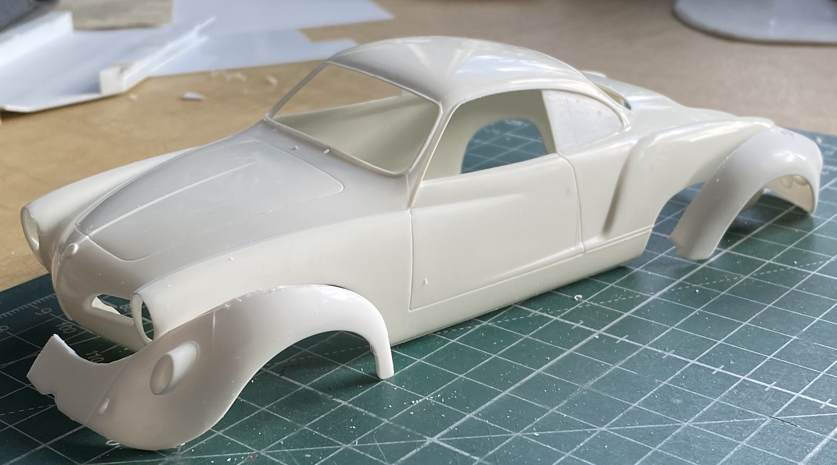
Both sets of fenders are roughly where they need to be. In looking at the rear, I can see that the back of this engine-sled isn’t going to look very Ghia-ish. Since I’ll be using the headlight buckets for brake lights, if the stock taillight positions are even visible after all the surgery, that would be a good place for backup lights. For certain, though, I’ll have no shortage of options for where the exits for air could be!
Mistakes teach us. I’ve learned a lot. The implication is that I make lots of mistakes…and that is true. Here comes another learning opportunity…
I’d seen a YouTube video (the name of the channel is “Model Car Muse”) where the content-creator used a woodburning tool to weld plastic (see the episode “Scale Model Body Modification Without Filler or Glue”). I decided that, since I’d been a metal finisher at art casting foundries, I wasn’t unfamiliar with using welding to fill a hole. I’d often had to fix a casting where something went very wrong with a section that in turn had to be excised and rebuilt using welding. There’s a big hole where there shouldn’t be one, so I went around the edges of the hole laying in welding bead until the hole wasn’t a hole anymore. I thought that I’d try that with styrene! My experiment with this was building up the underside of the rear of the body so that I could bring the belly-pan to meet it. I used a woodburning tool:
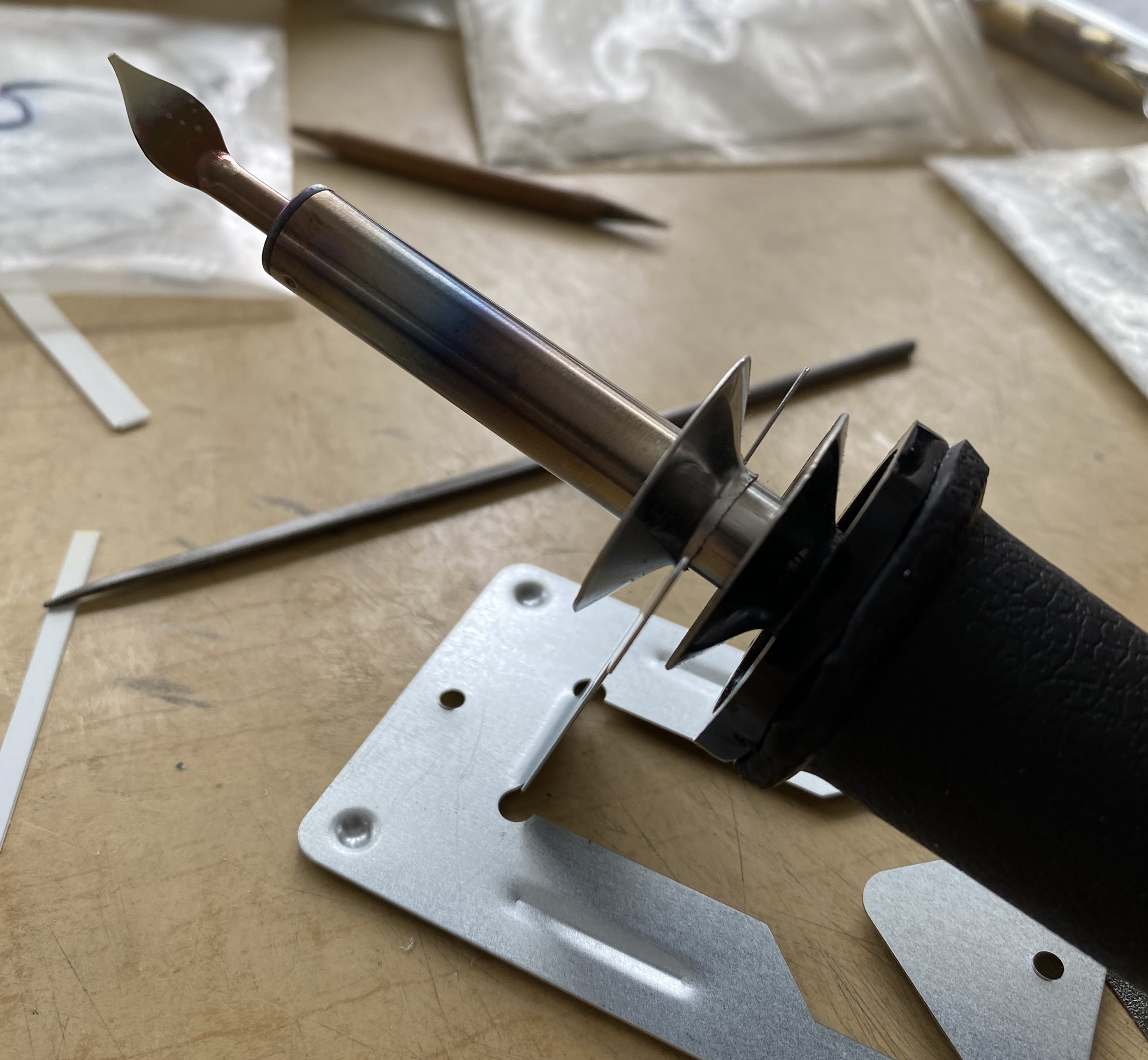
I then cut some sprue from the kit to use as “welding rod,” figuring that the same plastic as the body would probably be visually indistinct once it had been filed and sanded to shape. Then I started melting plastic (the engine cover is just tacked into place so that the body would be dimensionally stable):

Well…it worked, sort of. I discovered some things in this attempt. First, just like metal, cast plastic isn’t as dense as welded plastic. Welded plastic is HARD. I’d thought that being plastic, styrene cement would adhere to it, and it does, sort of…just not to the surface after being melted. The surface has to be ground/filed/sanded away and then the cement will work. Sort of. A large clamping force was needed and the resultant joint easily snapped. These sections of the body are compound curves (he says as if the remainder of the body wasn’t) and getting each side identical IS A BITCH. So the conclusion is that yes…welding plastic with a woodburning tool “works.” In this application it doesn’t work well enough to justify the large degree of work and fettling required. So I snapped them off and roughly cleaned up what was left. I can see a use for it down the line, just not here for this.
Moving on…
Once the glue had cured on the sponson extensions, dry-fitting showed gaps. I used .010″ (.254mm) and .005″ (.157mm) styrene scraps to fill the gaps between the edges of the extensions and the inside of the body:
Then I noticed that the belly-pan had gaps at the edges. Though not snug to begin with, I suspect that this had been exacerbated by shimming the sides of the extensions which pushed the sides of the body slightly outward. Again, with all of the dry-fitting ahead in mind, I decided to shim the edges of the belly-pan instead of all the on and off needed to fit the sponson extensions better:

I knew when I made the belly-pan that it was too short and would need to be lengthened, so I attended to that:
With the sponsons at this stage, they will also need to be lengthened. Before I can do that, I need to know exactly where the wheel openings are going to be. Before I can do that, I have to build more inner structure so that I can precisely determine where the powertrain is going to be, so the sponsons will be extended once I have made that determination. However, one of my goals is for there to be a minimum of 25 gallons fuel capacity. I took the measurements, converted to full-scale numbers, and determined how many of gallons the volume of these sponsons were. 11 gallons (41.64 liters) combined. In the above photo, there is a rectangle drawn just above where the pan has been extended. This is the space for the engine (considering tuneups, maintenance, etc. I would need space to get at the work). The space to either side can be additional fuel tanks! I haven’t done the numbers and conversions yet, waiting until they’re done before I drive myself to drink (any excuse, y’know) getting to the fuel capacity of them.
Torque would be a major concern if this was an actual car. The two forward lines drawn across the pan delineate where the doors are, which in turn delineates where the seats go, and so forth. I broke out the Mk I Eyecrometer and determined where I wanted the partition between the people space and engine space to be. The forward crosspiece is where that will be. The rear crosspiece is for structural rigidity and…oh wait! That’s an empty space! I could put more fuel in there! The thought is that the sponson tanks would be fuel cells. Since there is a float on an arm inside a gas (petrol) tank that enables the fuel gauge to work, I knew I was going to need a feed-tank for both fuel cells to feed into (which is where the fuel pumps would draw from) and that’s where the fuel sender assembly would go. The fuel gauge would always read “full” until both sponson tanks had emptied into the collection tank. Once the the fuel gauge began to move, it would be time to find a refueling place, the potential distance to which would be governed by the capacity of the collection tank and the distance this car could go on that amount of fuel:

Of course I’d glued (securely, of course) that second crosspiece in place before I realized that I could move it back and increase the fuel capacity, and therefore range, before the absence of go-juice turned the driver into an annoyed pedestrian. That will be taken care of!
And speaking of partition, it was time to get to work on that.
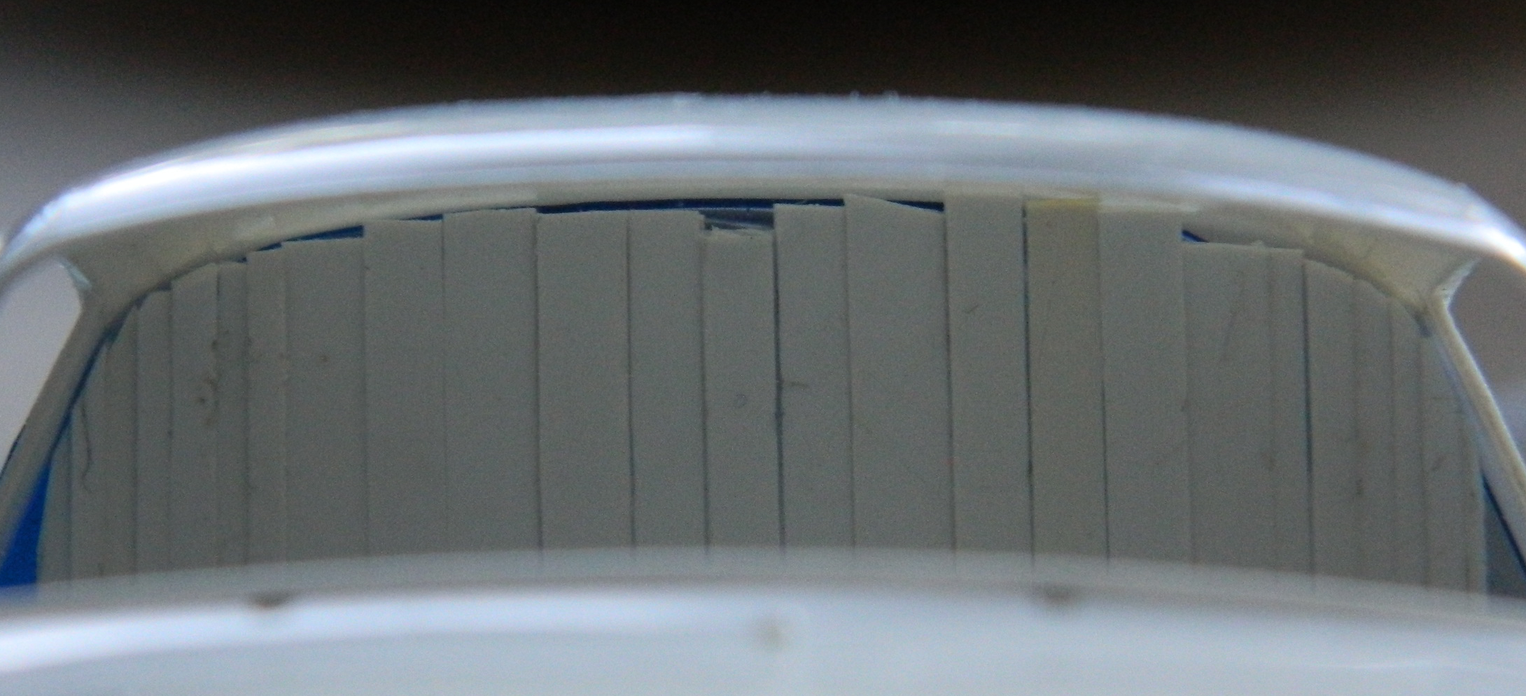
I HATE MATCHING AN INTERIOR CURVE. HATE IT HATE IT HATE IT. Yet match it I must. Ever see a contour gauge? That tool with all the movable wires that gets pressed across the face of a curve to be replicated? I have one. No. It doesn’t work all that well on something this small. But the idea of that gauge I could reproduce using strips of styrene. So I used .040″ (1.016mm) strips instead of wires. The body was placed over the monocoque and taped in place, then I placed one strip of plastic into the space between the two crosspieces and lightly glued it vertically at the base with the top (I thought) in contact with the roof. Subsequent strips were glued only to each other (I thought) in the same manner until I have a workable copy of the inside of the roof between the sponsons:
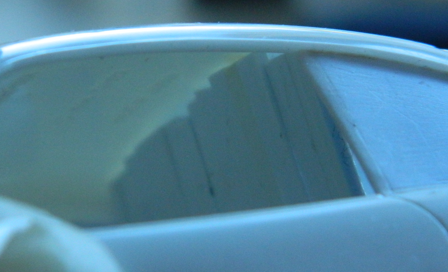
Yes…I see the space at the top of the center strip. Now. I didn’t then and just continued blithely on with it.
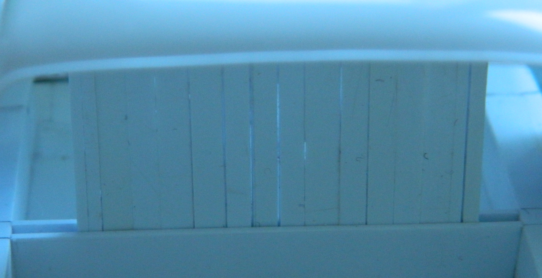
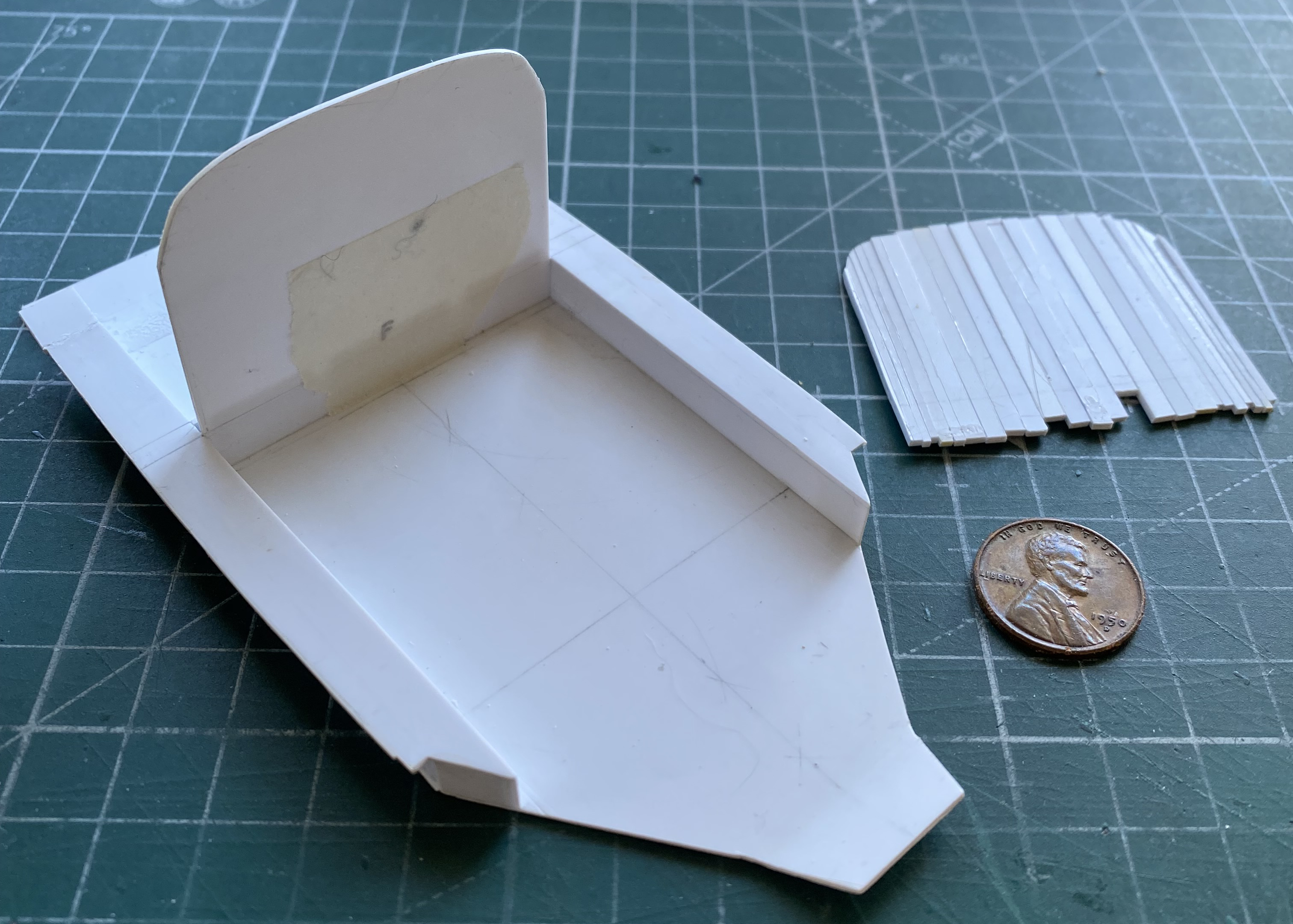
But I got it to work in spite of myself:

And then traced it onto .030″ (.762mm)” for rigidity:
And then the fitting happened…and happened…and happened… Finally my brain decided to join the party and I realized that I would be adding a strip of styrene on either side of this partition because in reality, I would need to attach this to the roof somehow:
Certainly good enough!
Now to add the wings using the same procedure with styrene strips, only using .015″ (.381mm) for ease of removal:
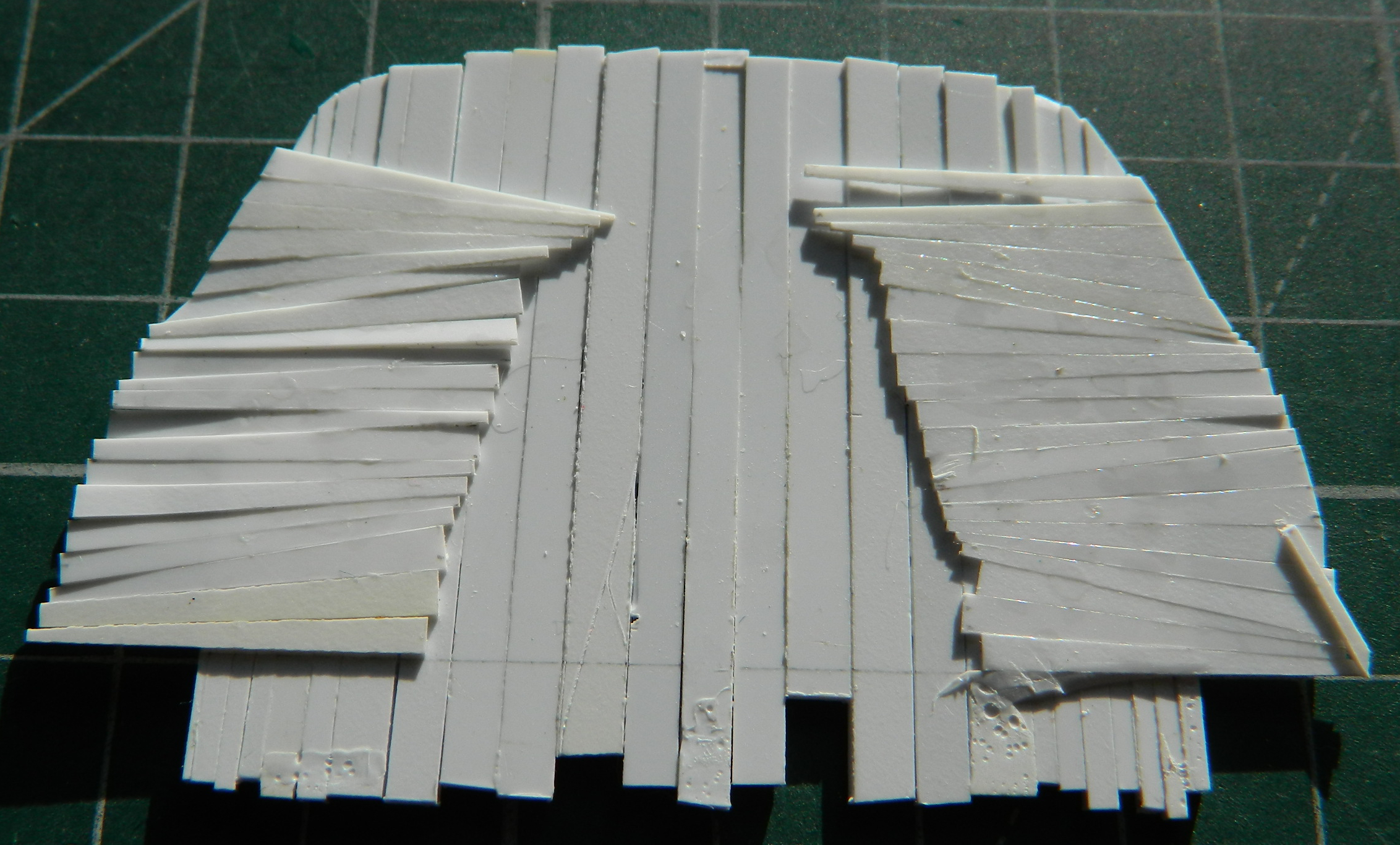
It ain’t pretty, but it worked. I added the wings of the same thickness as the center section of the partition:
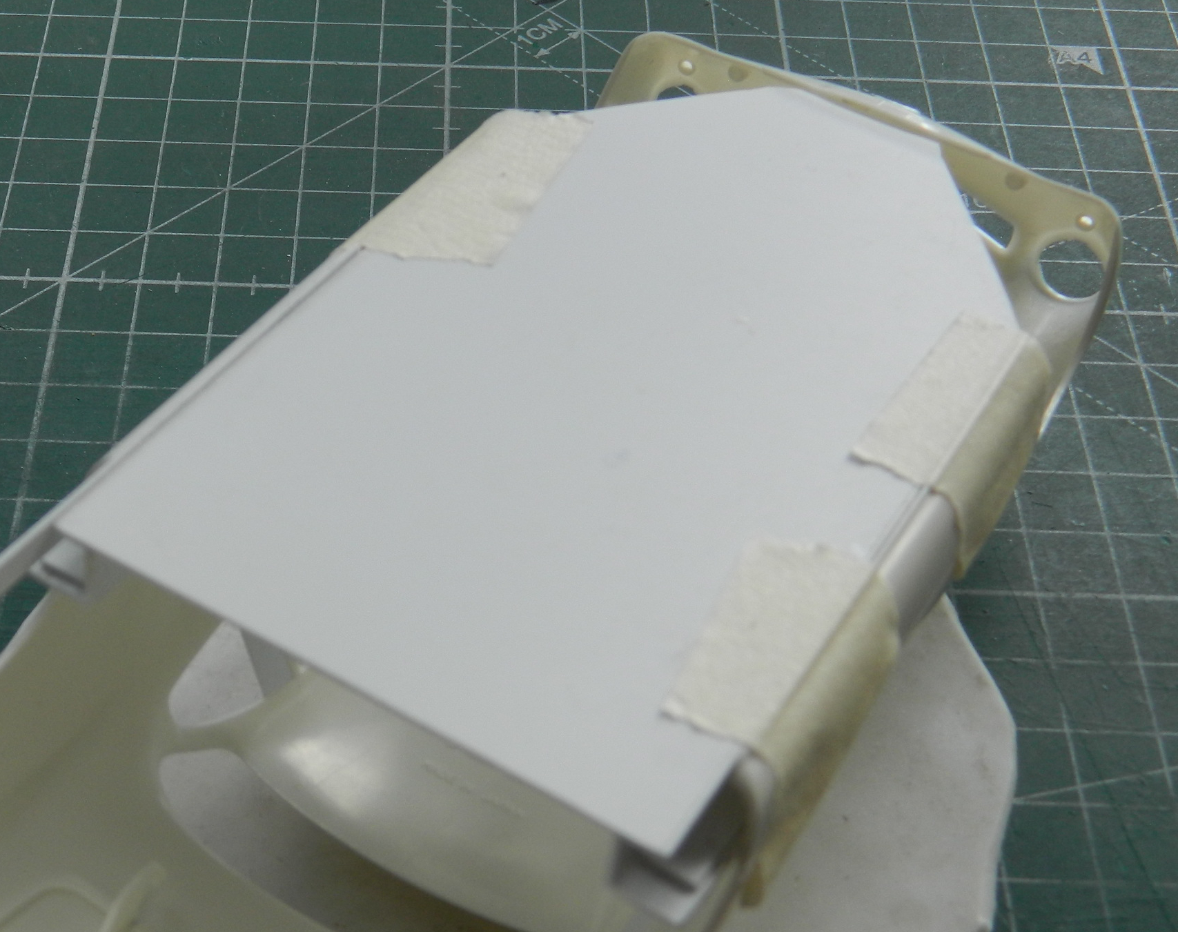
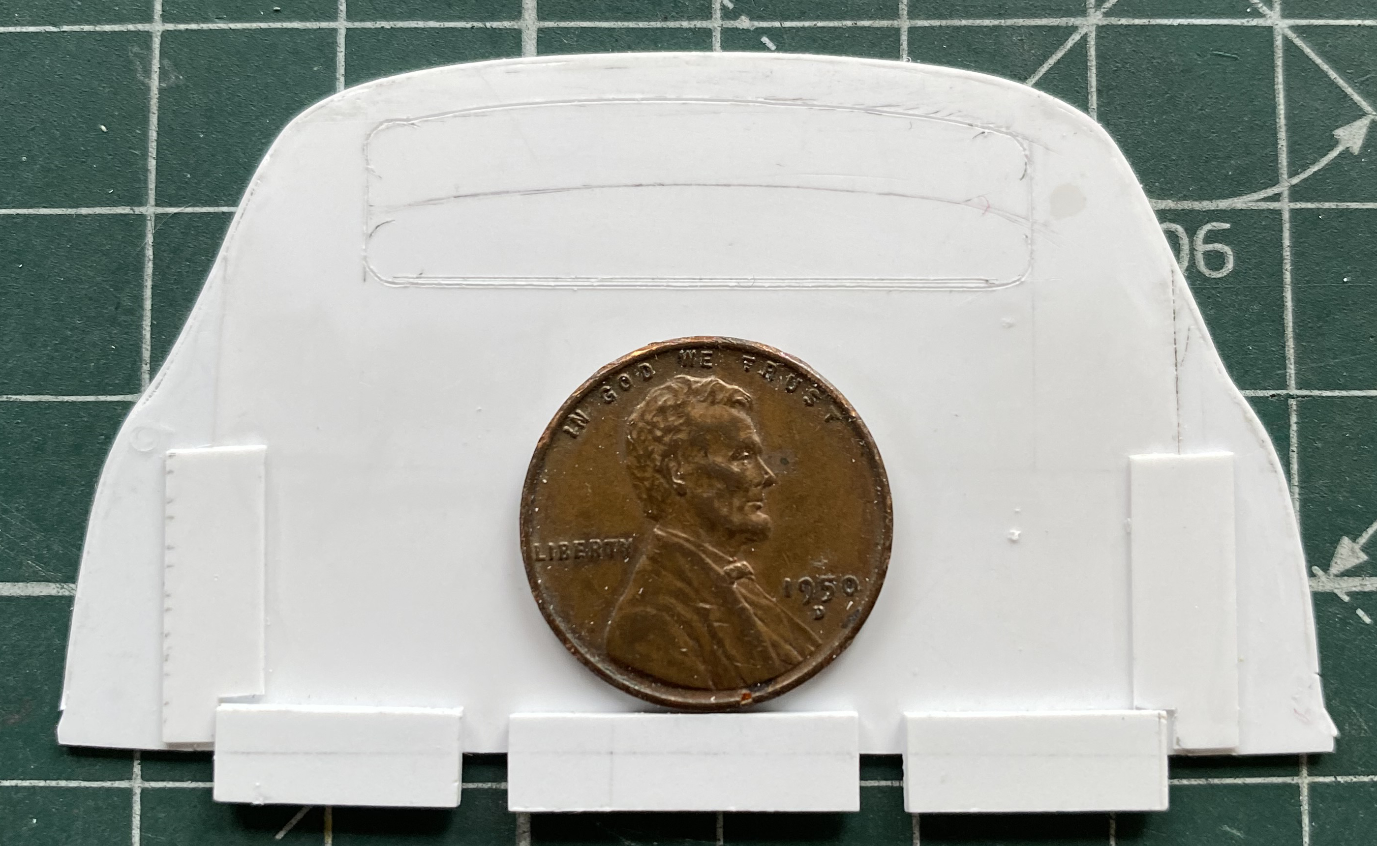
Once fitted (and yes…it was as tedious as the last one was), I added structural support to the back and then laid out the rear window and cut the opening:

I learned my lesson with the M4 build as to how difficult it can be to fit clear styrene into an opening. I’m not doing that again. What I am doing is to using a sheet of .015″ (.381mm) clear and sandwich the clear between the part I just made and the one I’m about to make, also of .015″ (.381mm):
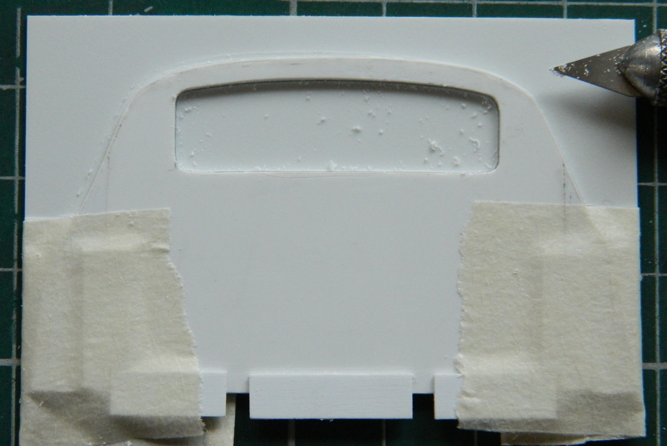

I placed the clear panel in place and then added .015″ (.381mm) around it for structure and to keep the clear panel from having any ability to move and then glued everything down:

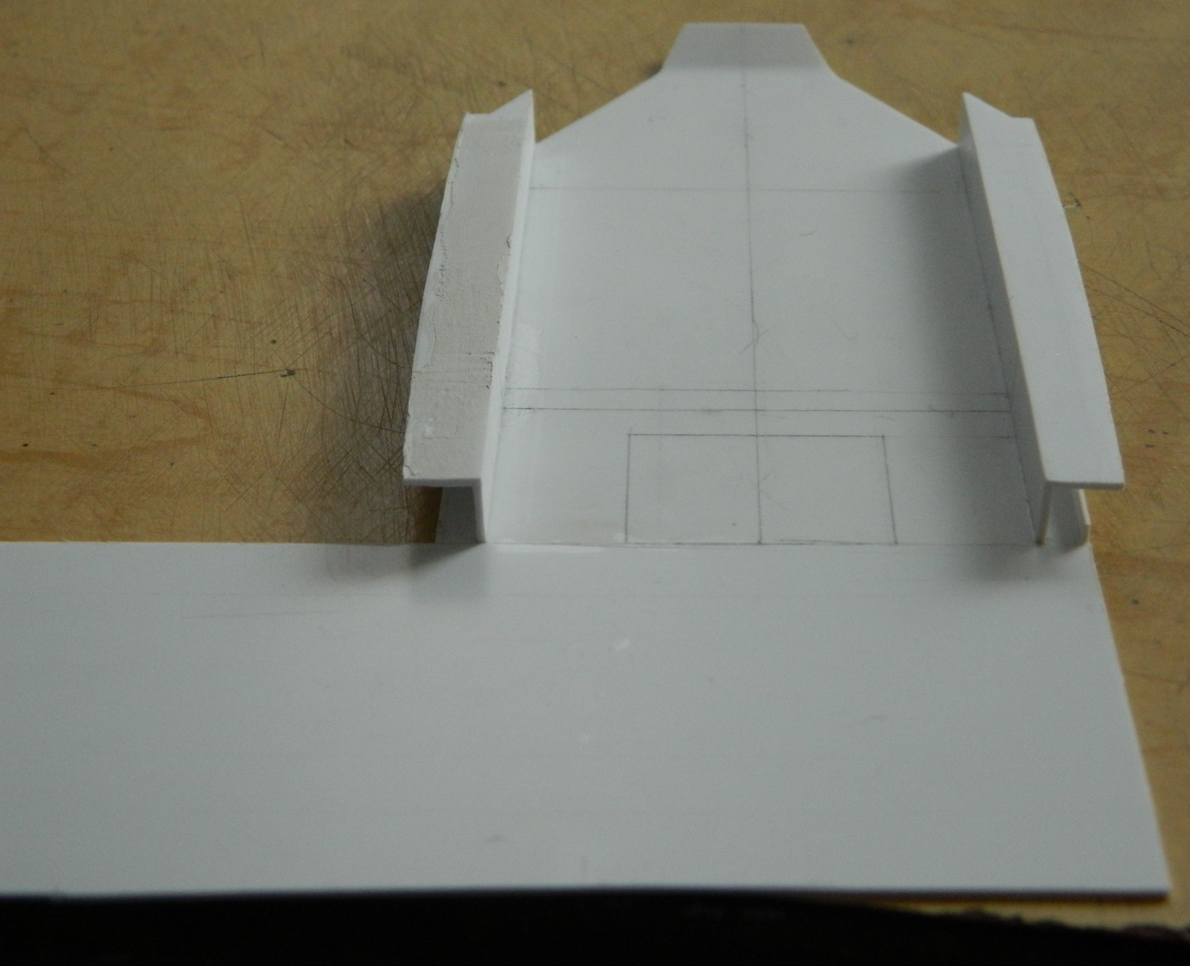
Then it was time to join the front to the back and check fit:

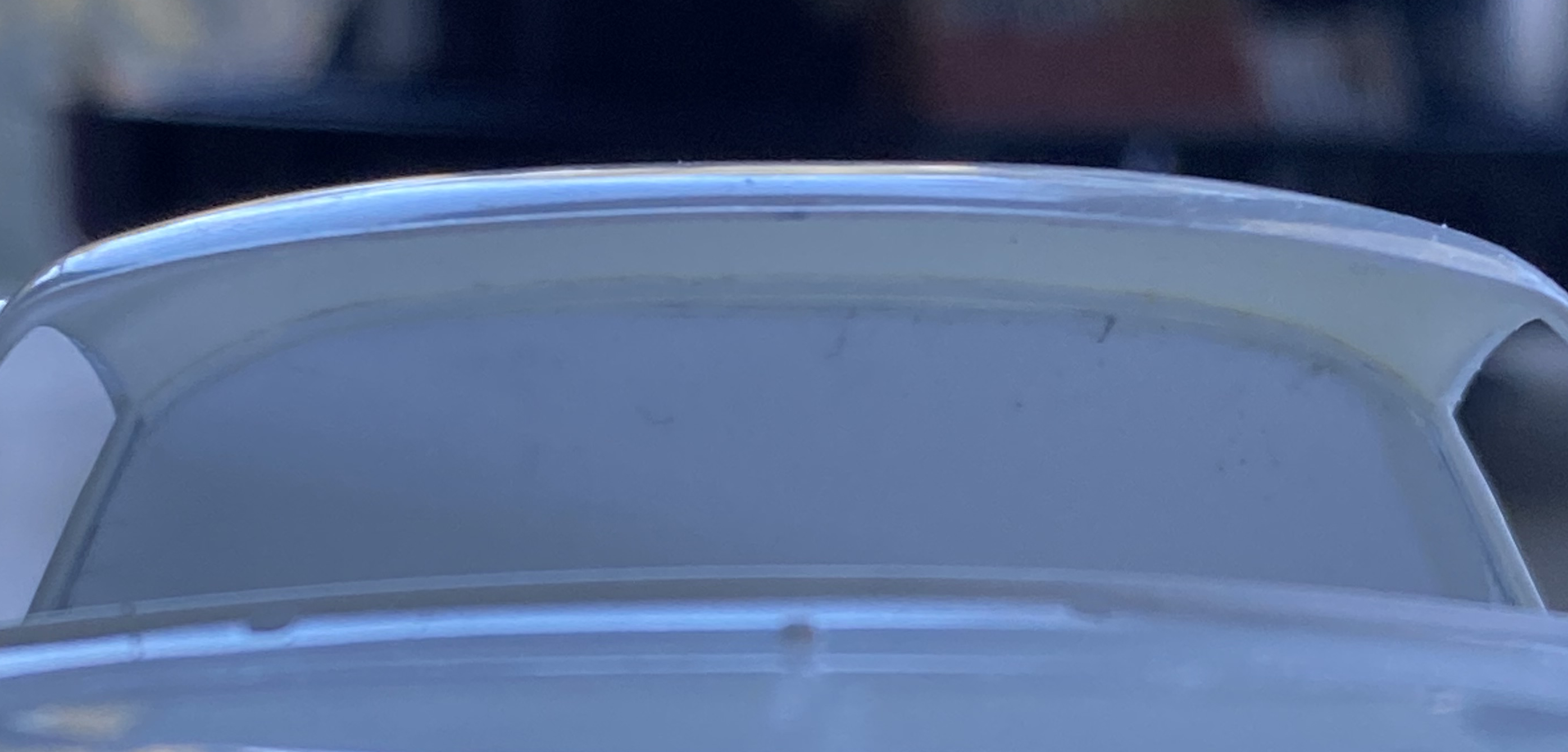
Fits there…let’s see if the Eyecrometer got the window opening correct relative to the body:
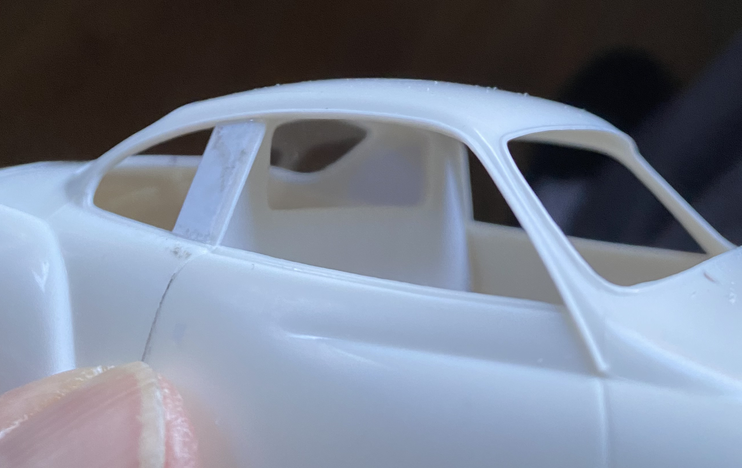
Yep! Just where I wanted it.
