The landing gear bays with this kit are large, which I guess shouldn’t surprise me since this kite used a pair of the P/W R2800 which weren’t known for being small. Once upon a time, I would take the opportunity to detail the hell out of these bays as I did with the Blackbird build. And then I realized how infrequently the ‘Bird gets picked up and someone actually looks inside the landing gear bays. Not anymore. I’ve added some structure, the ribs and stringers, that could be seen, but I’m not adding hydraulic lines, cables, or wiring harnesses. The last update showed the ribs being built and installed, meaning this update will show the stringers.
The journey of a thousand mishaps begins with the first step and this is where I’d ended the previous update:
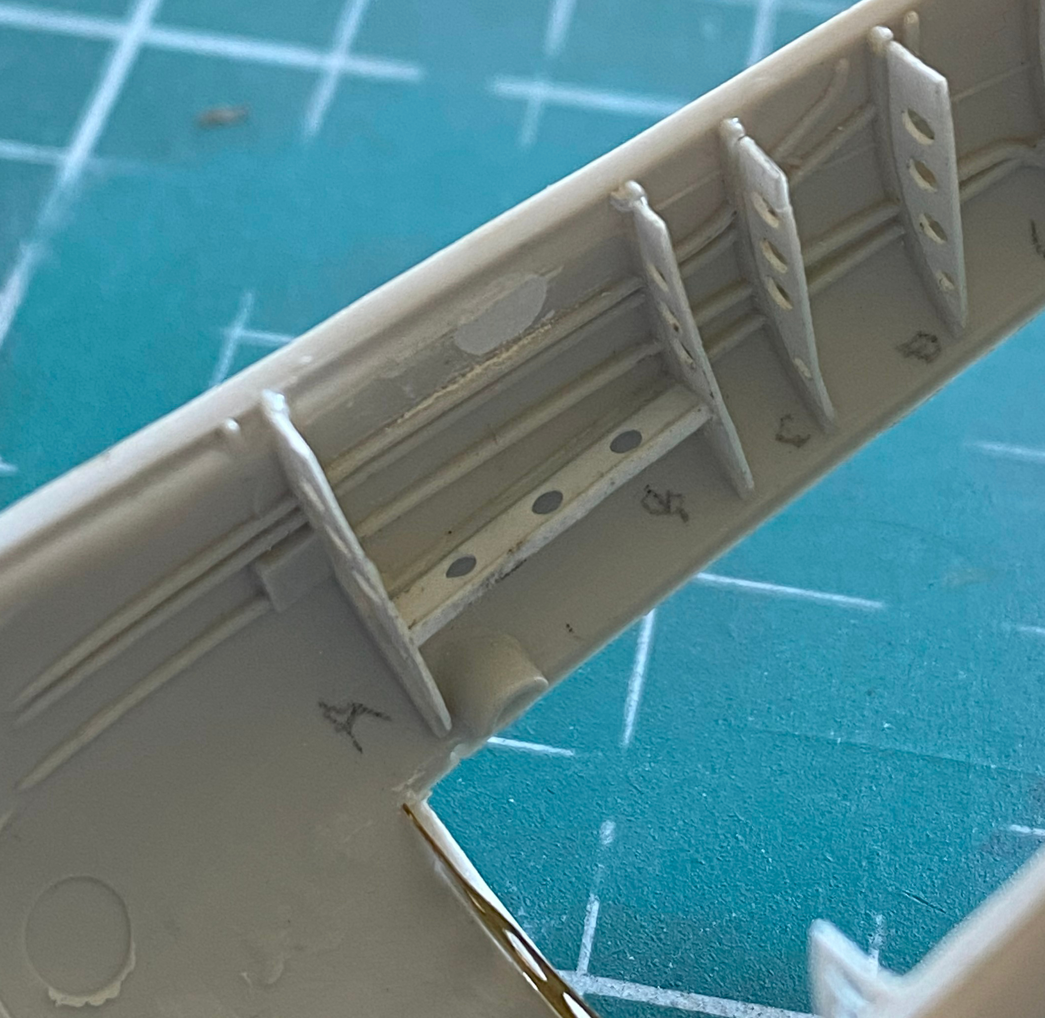
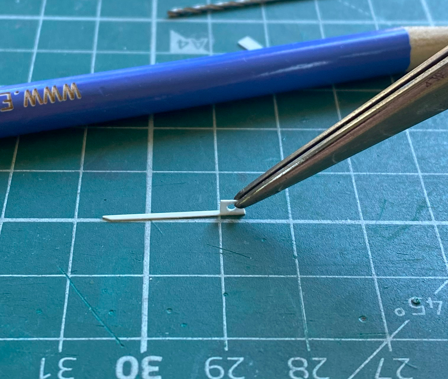
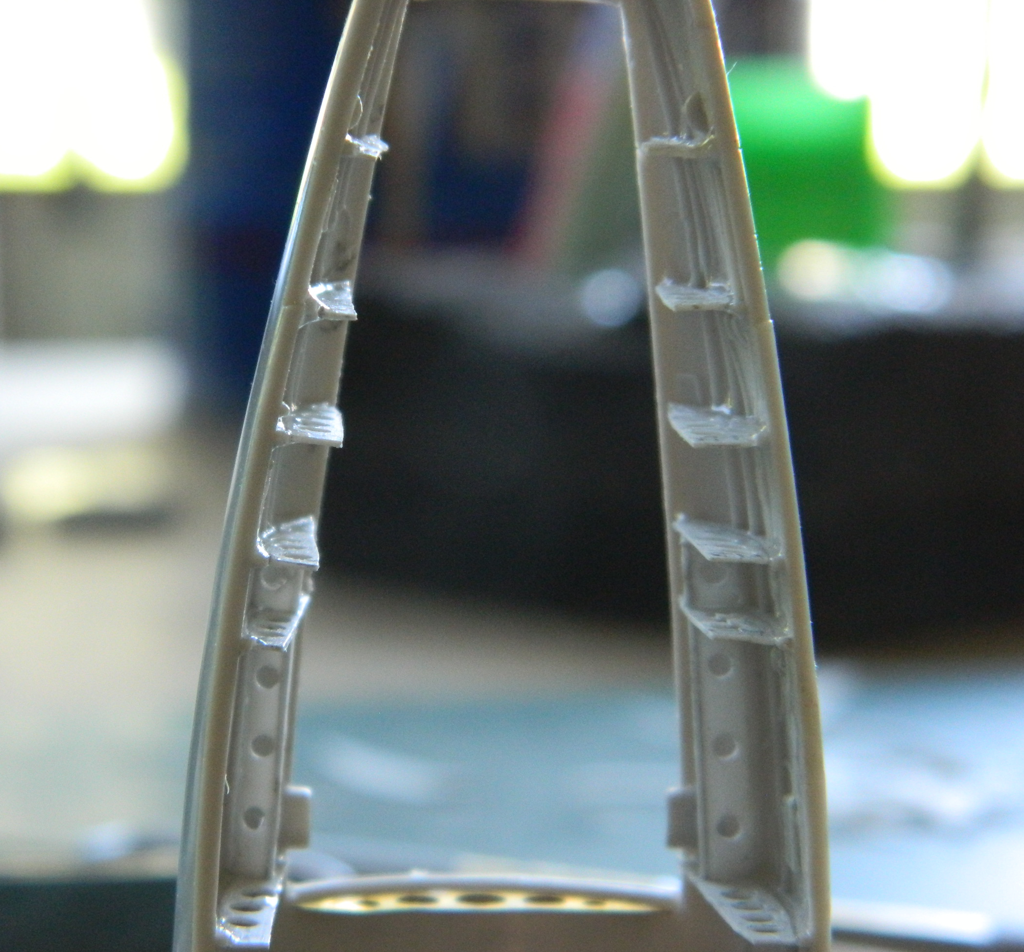
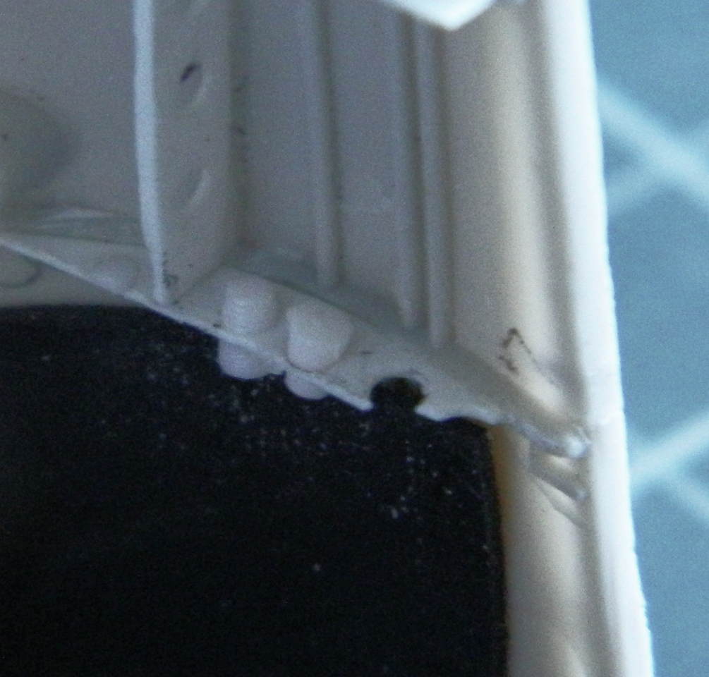
There isn’t a lot of photos in this update because of things like this, which is adding the lip that the stringers had (all 24 of them). Small details take time. I used 0.010″ (.254mm) for both the stringers and the lips. Once I had the approximate dimensions, essentially the length and width, the lips got added before the absoLUTE joy of fitting all these things in:
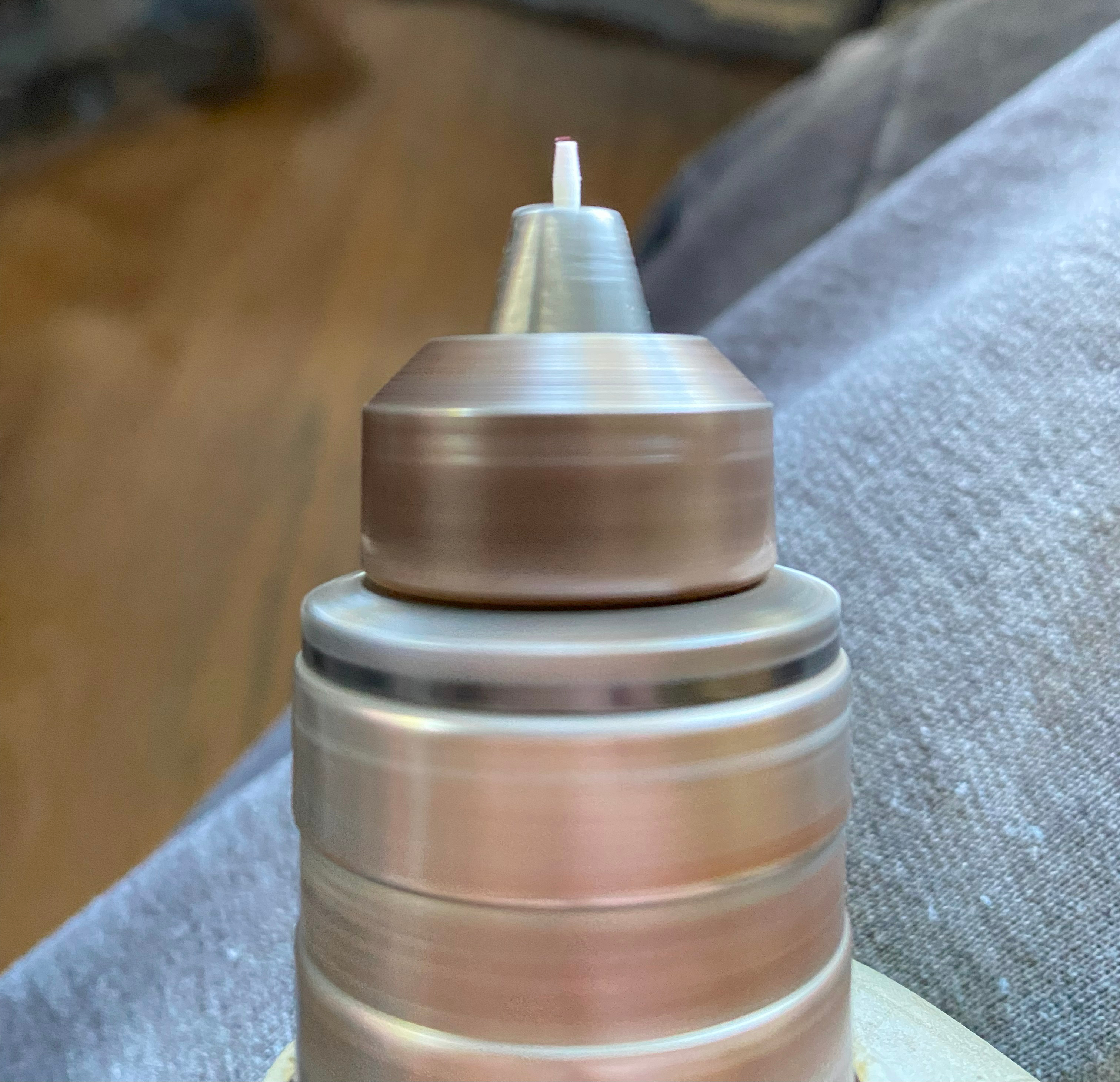
Now that I have a new tool to play with, specifically UV-setting resin, I used it more and more during this phase of the build and my conclusion is that this stuff is DEFINITELY useful. When dealing with a new item, I always read the directions. The directions of this stuff tells me that I can’t rely on natural sunlight to cure it. Well… I used the provided UV light to cure the resin and that works well, sort of like superglue with plenty of time to get the parts correctly positioned. And like how I use superglue, I put a small drop of the resin on my worktable and added it to the model using needles and dental tools. What I did notice, however, is that the resin will end up being cured somewhat by just sunlight. This is what happened after about five minutes of exposure to direct sunlight:
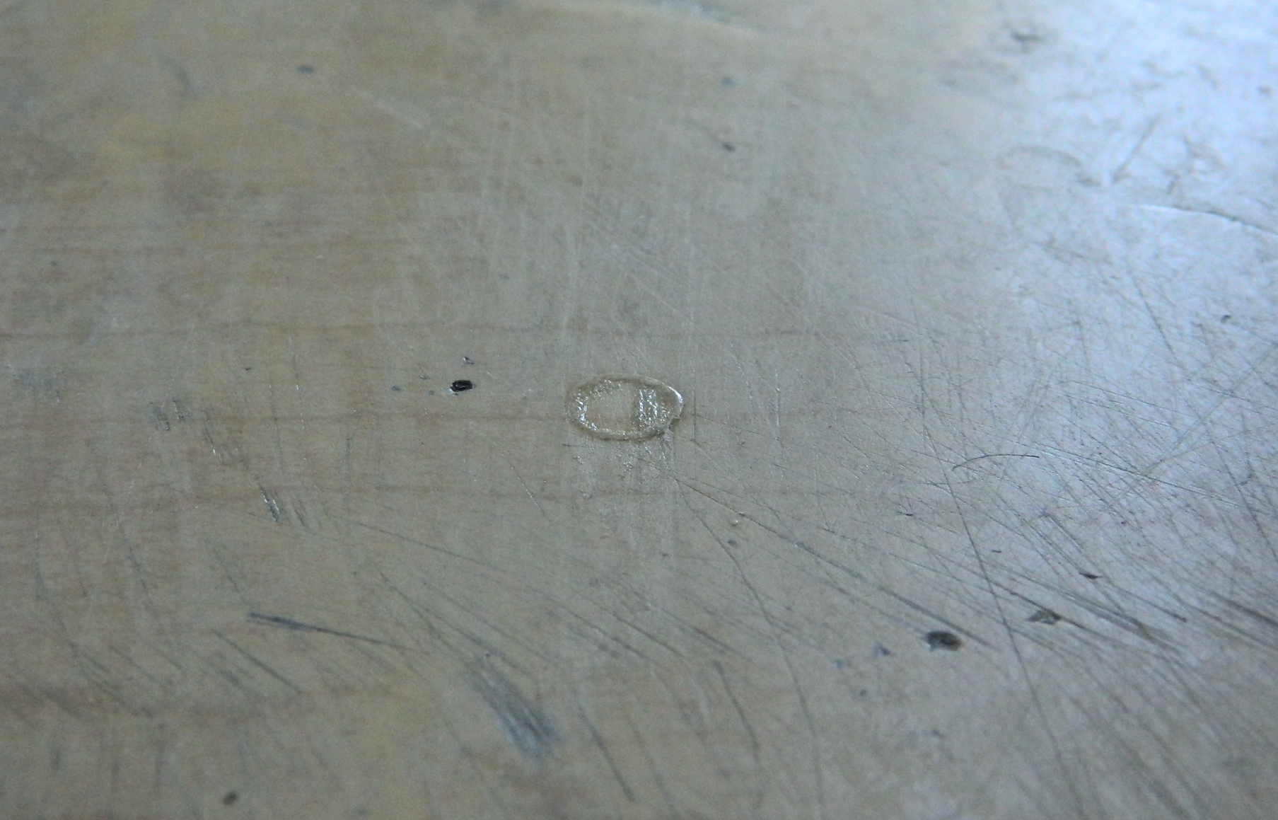
I’m pretty sure I’ve mentioned in other places in this site that I’m parsimonious. And I’m also a cheap bastid. Wasting product, any product, is right near the top of my must-avoid list. So since sunlight will cause partial curing, which is wasteful of product, I took a piece of cardboard scrap and fashioned a sun-shield with it:
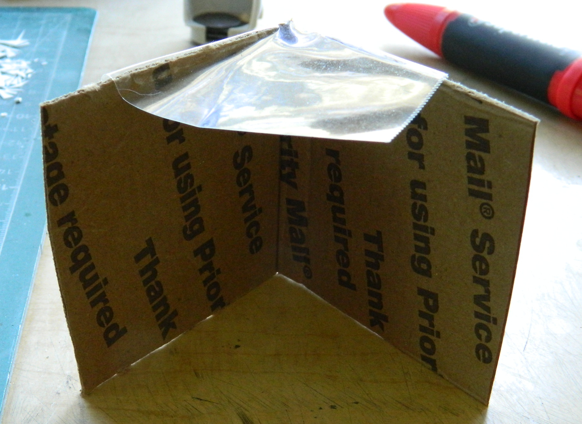
Though the drop of resin will still cure on the table, that rate of curing is substantially slowed. Best I can do so that’s good enough.
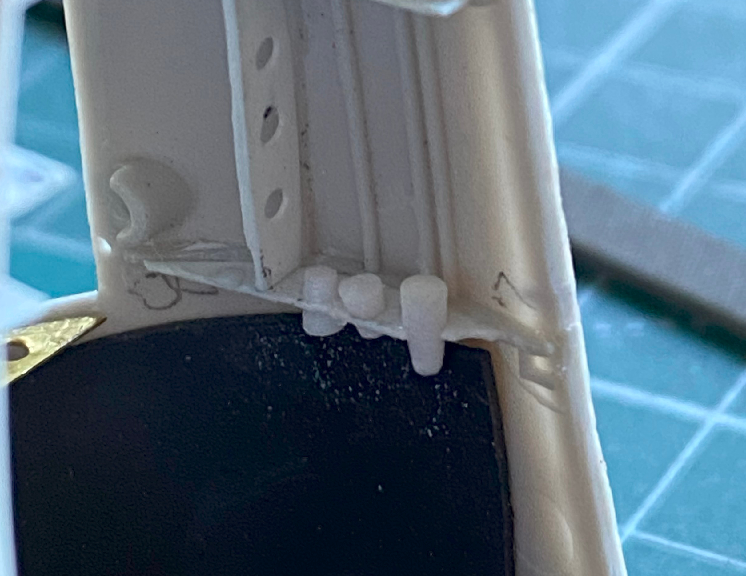
So I made a lot more stringers and lips:

I discovered quickly that I can forget which side of which nacelle any given part is intended for. To counteract that, as I made a stringer, I trimmed, fitted, and glued it in place using the UV-setting resin:
I just kept plugging away at it until I got both nacelles done:
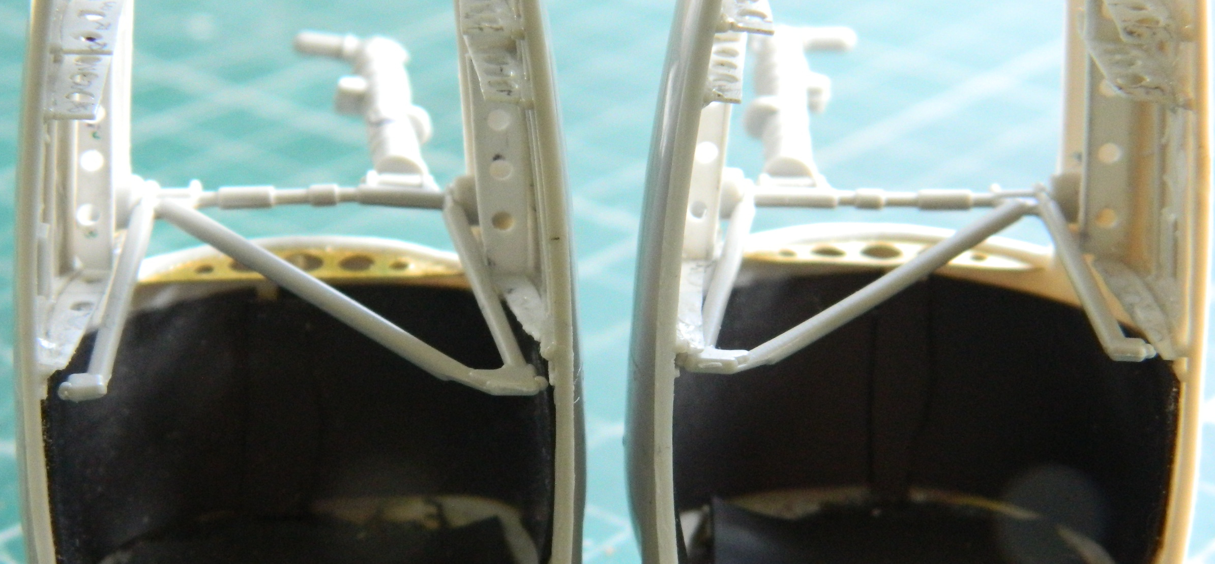
With the ribs and stringers done as much as I’m going to do them, it’s time to fit the landing gear leg assemblies into place…and that took a bit of doing to accomplish. I used the kit’s plastic struts as my gauge because the SAC metal legs are direct copies of the kit parts. I learned a couple of things during this process. The first being that to save myself major hassle, I’m going to break from my usual process of waiting to add the landing gear until late in the build (less chance of breaking them, obviously). When I tried feeding the struts into place through the opening at the bottom of the nacelle I quickly understood what a pain in the ass this would be if I added them after the nacelles were glued to the wings. This time I’ll be adding the struts before the nacelle is glued (and puttied, because dry-fitting showed me that it’s needed) because fitting them into their proper places is SO MUCH easier when going at that task from the much wider top of the nacelles. The second thing I learned is that the ribs in front of the openings are too wide. The brace arms of the strut are in sufficient enough contact with the front ribs to bend those struts (the struts that are being bent are the ones in contact with the ribs on either side of them):

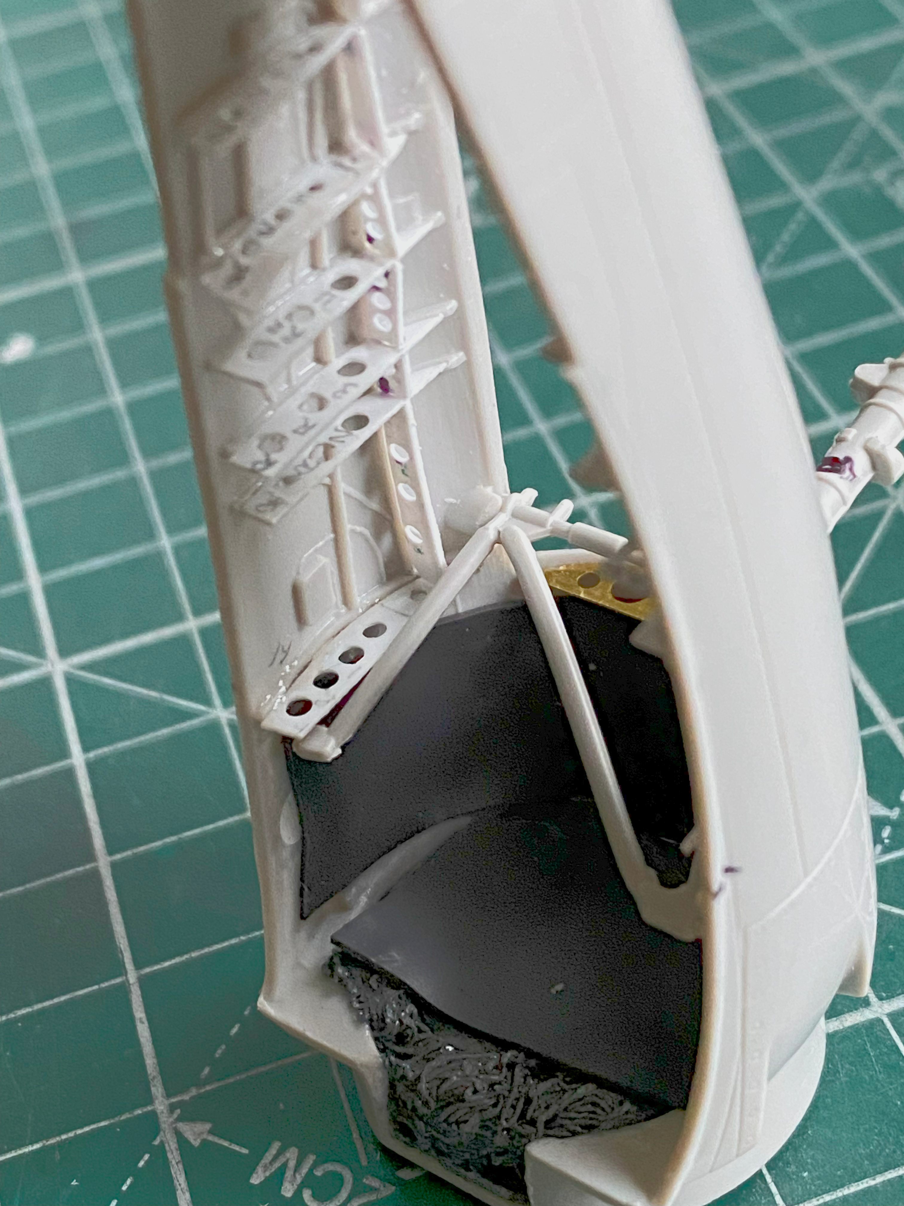

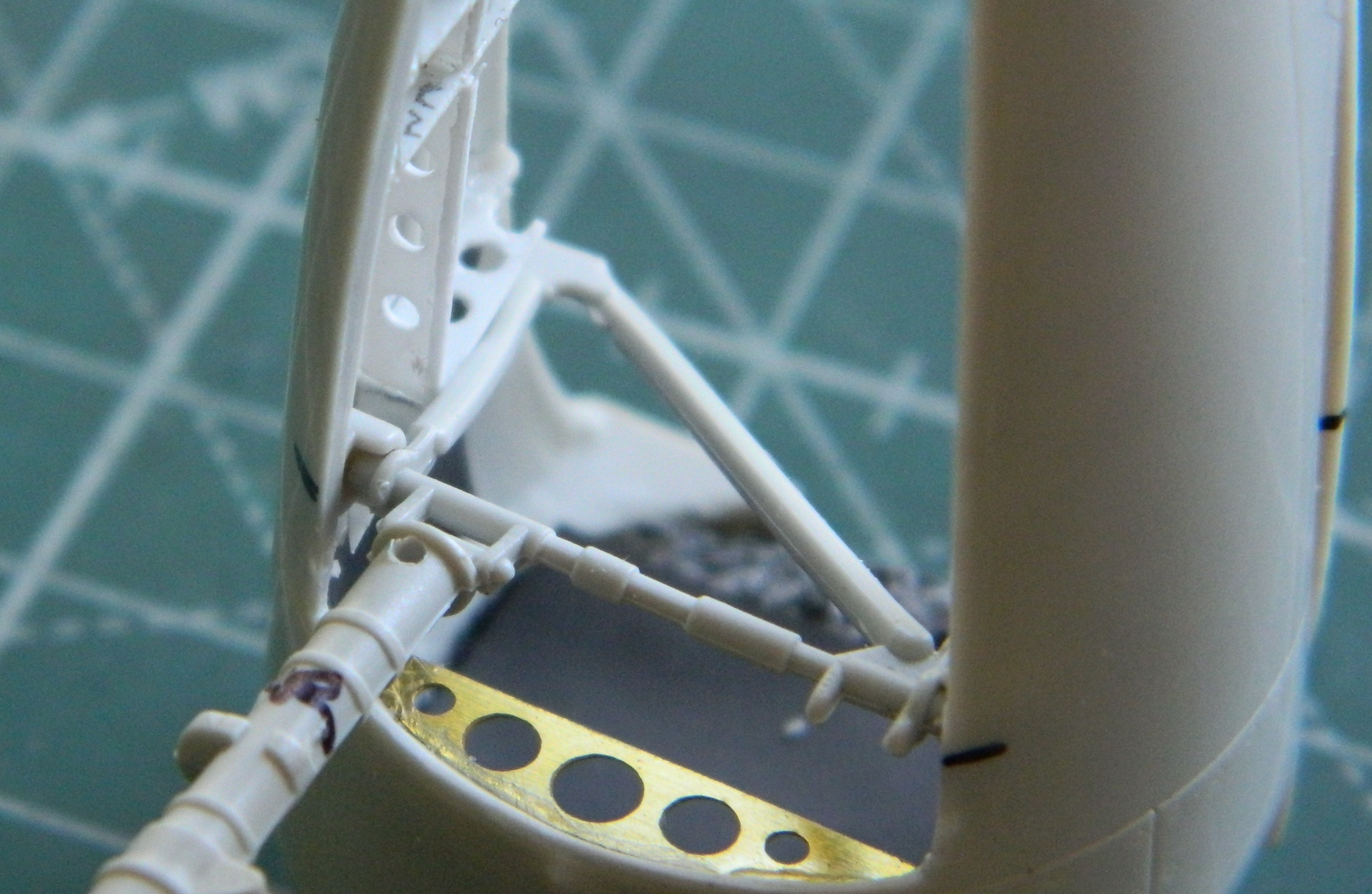
This photo shows how far away the struts are from where they’re supposed to be mounted:
I like emery boards for jobs like this. Good abrasive, stiff, and can easily be shaped to fit the task at hand. Here I’d split the emery board lengthwise and then snipped the rounded ends off (using wire cutters), something I could also do as the abrasives wore away:

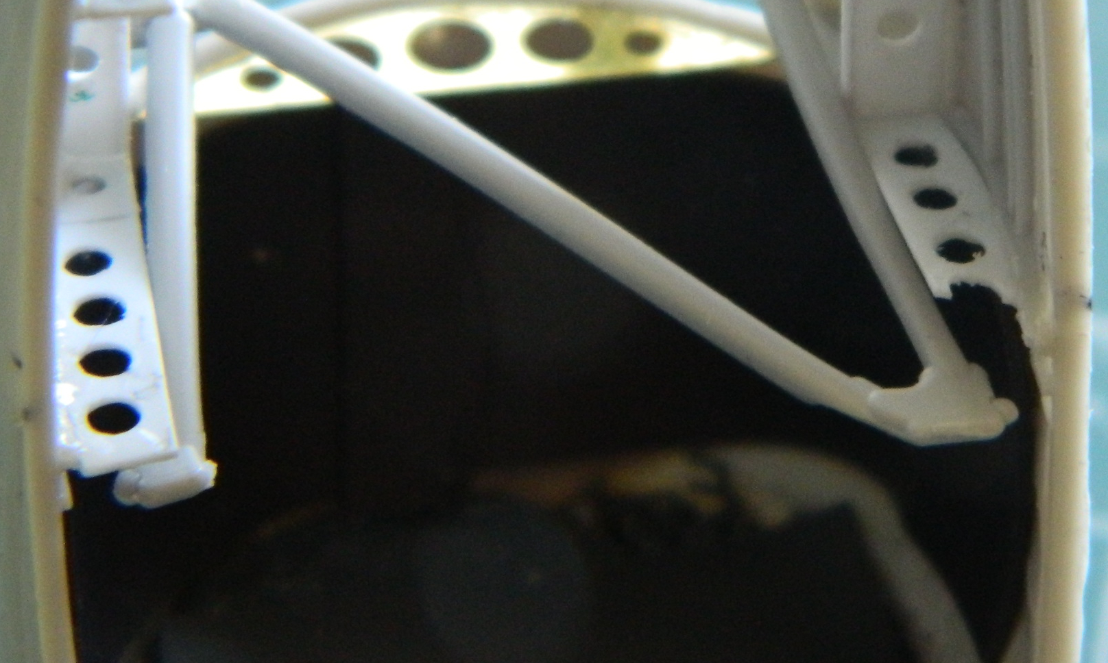
I marked the section of the ribs that needed to be trimmed back and dry-fitted frequently. It became evident that I had to remove enough of the ribs which would cause the lightening holes I drilled into the ribs to be sanded through the edge of. That means I either have to pop those ribs and stringers out and redo them (No. No way.) Or fix them in situ. I opted for that and I used a piece of 0.062″ (1.57mm) Evergreen styrene rod to fill the holes that had to be filled. The rod was a little bit larger in diameter than the holes I needed to plug, so I cut a short section, chucked that section into a variable-speed drill, then spun it slowly while tapering the end of the rod with a file:
Then I started filling the holes. Using styrene cement means that I have to let the glued part sit for a few hours (preferably overnight) so that the plastic, already very thin, would be as solid as styrene can be when I started working it. After a few days of glacially slow progress this way, I finally realized that I should be using the UV-setting resin for this, so I switched to that and the progress of filling holes went much faster:


Once I finished down the plugs, I went back at the ribs with the modified emery board until clearance was achieved:
I have also been filling every available space in front of the pivot point (defined by where the main landing gear contacts the surface it’s sitting on) with weighty bits. Most of the added weight is lead. In addition to the flattened lead balls inside the nacelle, I stuffed what space was around them with lead wool on the right side and sliced .093″ (2.36mm) lead solder on the left side (you can see the lead in previous photos). Once glued, I lined the forward bottom with tungsten tape (this is used to adjust the weight/balance of a pickleball paddle, if you want any of it) and put another piece across the back of the lead balls. This shows how much added weight there is:

The next step is to paint the inside of both nacelles flat black. Since I’m going to be loading the airbrush, I also want to paint the engines while the airbrush is loaded with the flat black.
But that’s it for this month…
