I’m doing something a little different with this update. Typically, I post updates on or about the last weekend of the month. I’m updating early because I saw that I had taken over 50 photos this month so far. Typically, it takes me 6-8 hours to do an update; editing photos and coming up with this snappy commentary (so called because sometimes my commentary can bring me to the point where I’m ready to snap)…and that’s with 30 or so photos to edit. So rather than spend all weekend doing an update if I kept to my typical schedule, because January is only half over and I have more work to do, I decided (obviously) to break January’s update into this part and the one coming on the last weekend of the month.
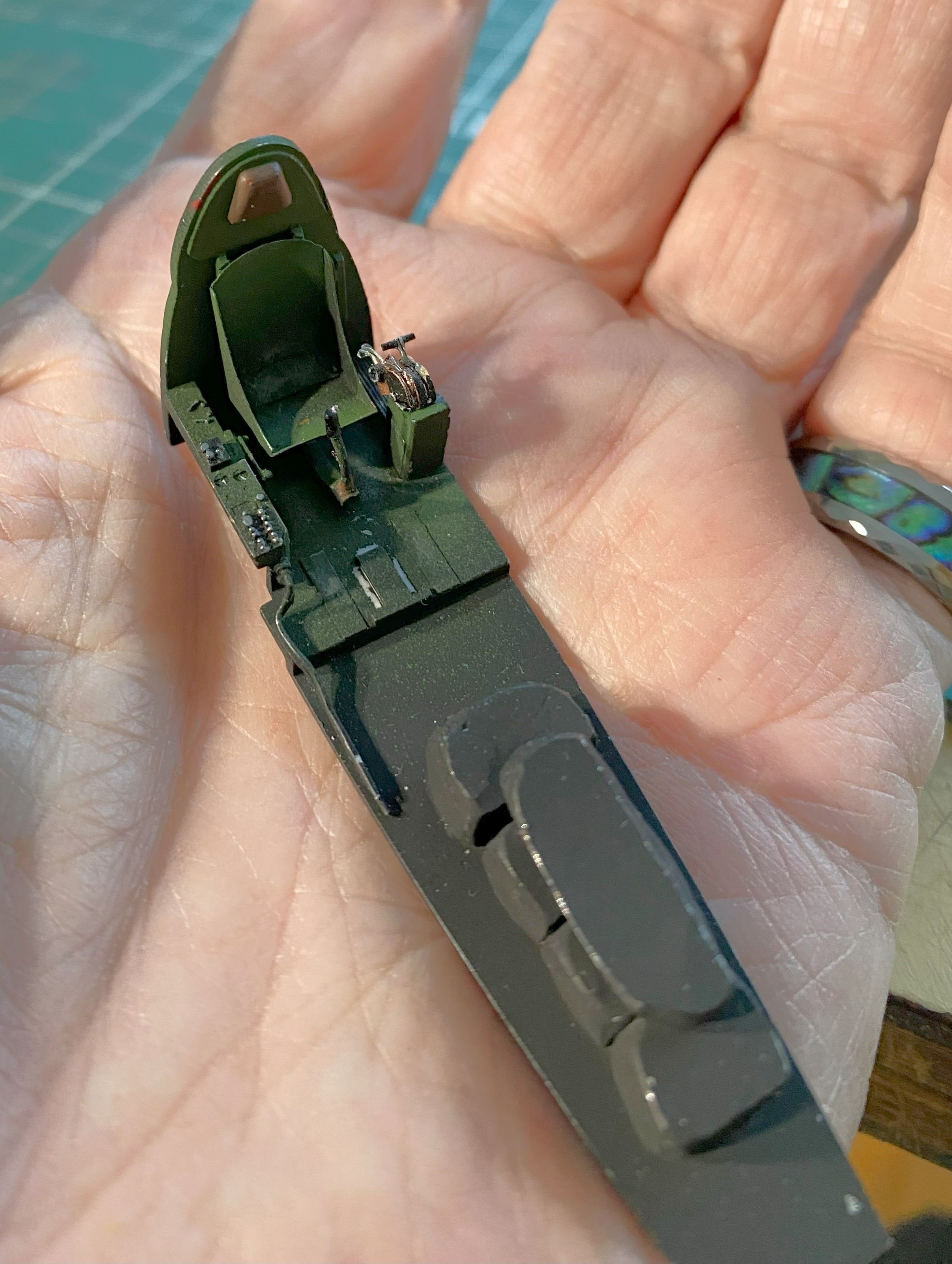
I was still populating the cockpit with scratchbuilt bits. The Tigercat had a parking brake so I added one. That started with making the mount for the T-handle of the brake:
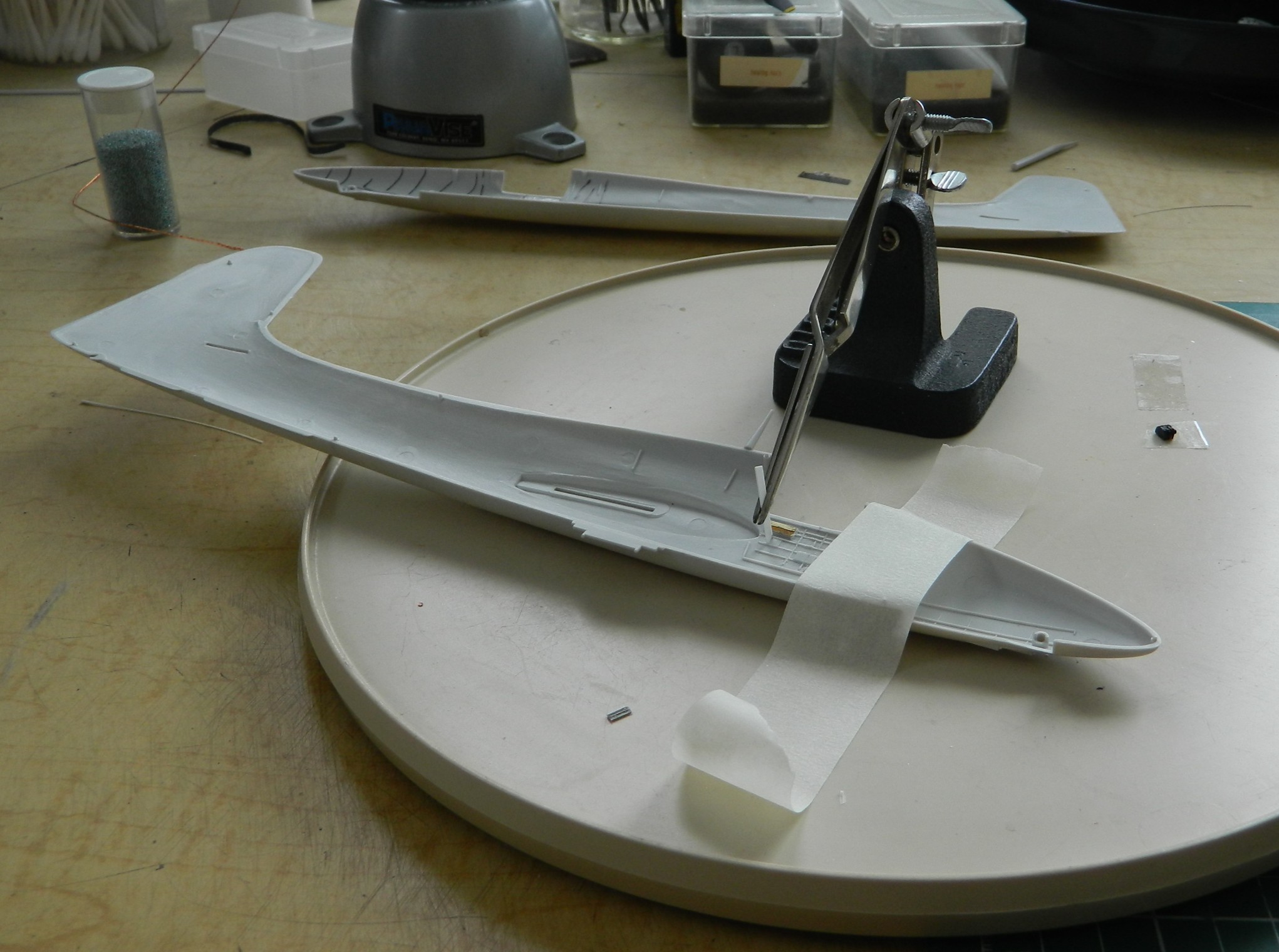
A very handy tool for those of you who scratchbuild is a “lazy Susan,” a platform that will rotate. Working small parts often requires the modeler to have four (or more) hands. I use jeweler’s tweezers to help with that. Alignment of the bit being added or constructed is critical. To get the alignment you want (which is, hopefully, the alignment you need) will require you to look at the join from multiple angles. If the parts and jeweler’s tweezers just sit on your working surface, it can be challenging (or next to impossible) to get the views you need without disturbing what you’re working on. Putting the jeweler’s tweezers and work on a rotating surface allows you to accomplish that. You can rotate them to the view you need to make the construction work correctly:
Last month while dealing with the seemingly never-ending throttle quadrant, dry-fitting showed me that I’d placed the imagineered pedestal too far forward. That got fixed:
I’d placed a small alignment mark on the floor of the cockpit and then promptly forgot that that mark was for the front of the pedestal, not the rear as I had mistakenly thought. Oops. (Again.)
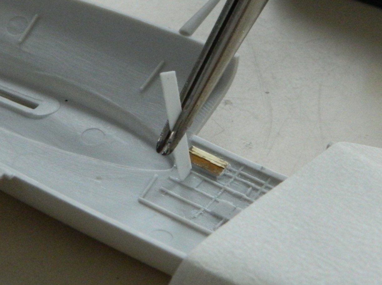
A prominent feature that the kit didn’t provide is the flap actuator lever. Construction-wise, it’s similar to a throttle quadrant but only needed four parts. Wrestling and cursing during the construction of the throttle quadrant made this part easy to build by comparison. I used 0.010″ (.254mm) copper shim stock and a 22 gauge wire for the lever that I flattened with a hammer (the bit coming off to the upper right is just a spacer):

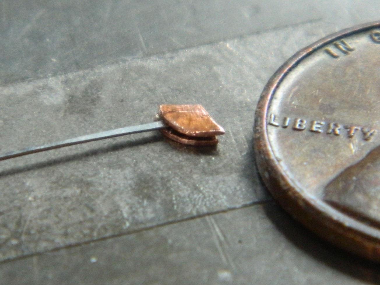
Then I used the jeweler’s tweezers, the lazy-Susan, and a bit of stretched sprue to make the handle (you can see the T-handle, also made of sprue, glued into position as well):

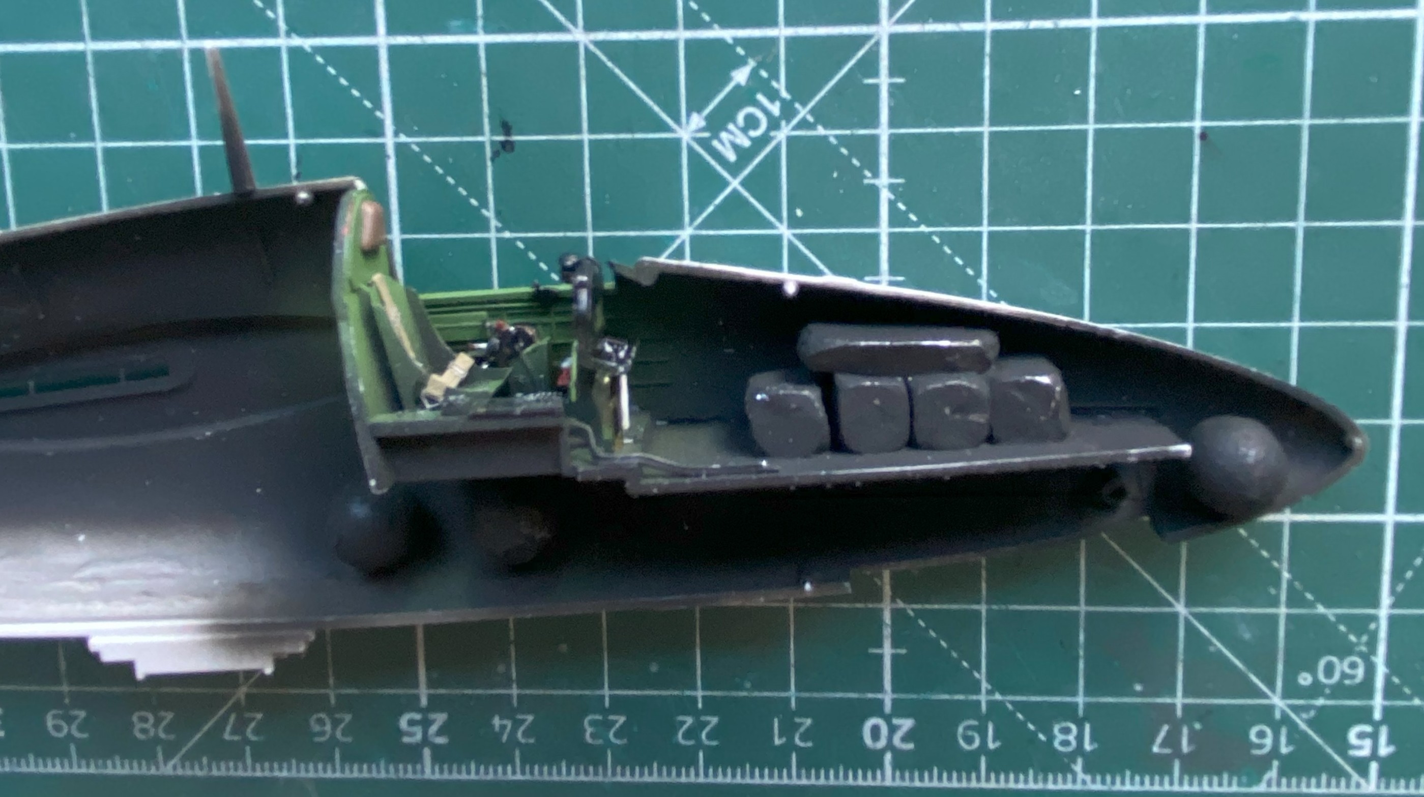
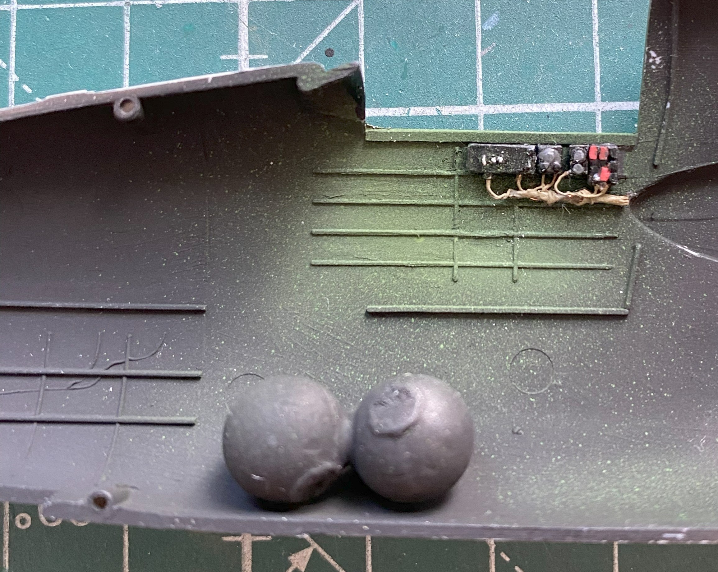
When I did my most recent balance check, though the thing would sit on its nosewheel, I wanted it planted on its nose with more authority. Having checked where I could put more weight, I added more .36 caliber balls (because what says “authority” like balls do?):

The nosewheel bay has no bulkheads with this kit. I hate matching interior curves. Since I am spending less time on details that won’t be seen or require the observer to pick up the model to see them, I’m not adding those bulkheads. I’m cheaping out by painting everything that could be seen through the front landing bay opening flat black (and the engine cooling flap parts, since they needed more):

Later on during dry-fitting, I realized I needed to extend the flat black further reward, which was attended to.
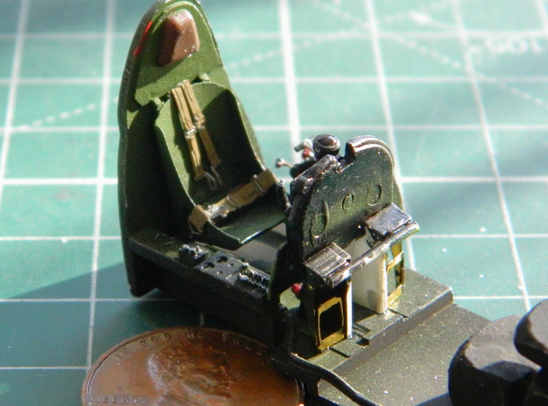
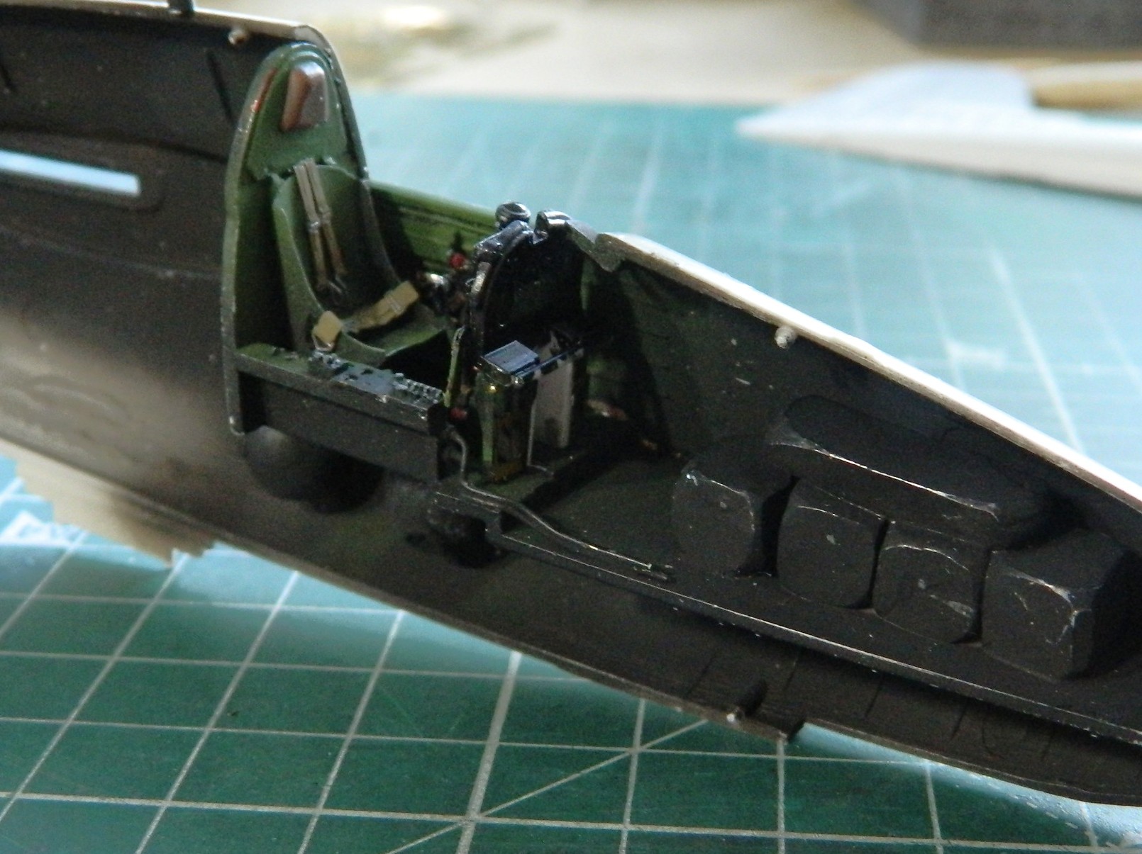
I held off adding the cockpit to its location because another annoying habit I have is that as soon as I paint something, I am reminded of what I’ve yet to build before I should paint. Here I am, blithely assuming that I’ve gotten all the cockpit parts painted and a little bit of wear added:

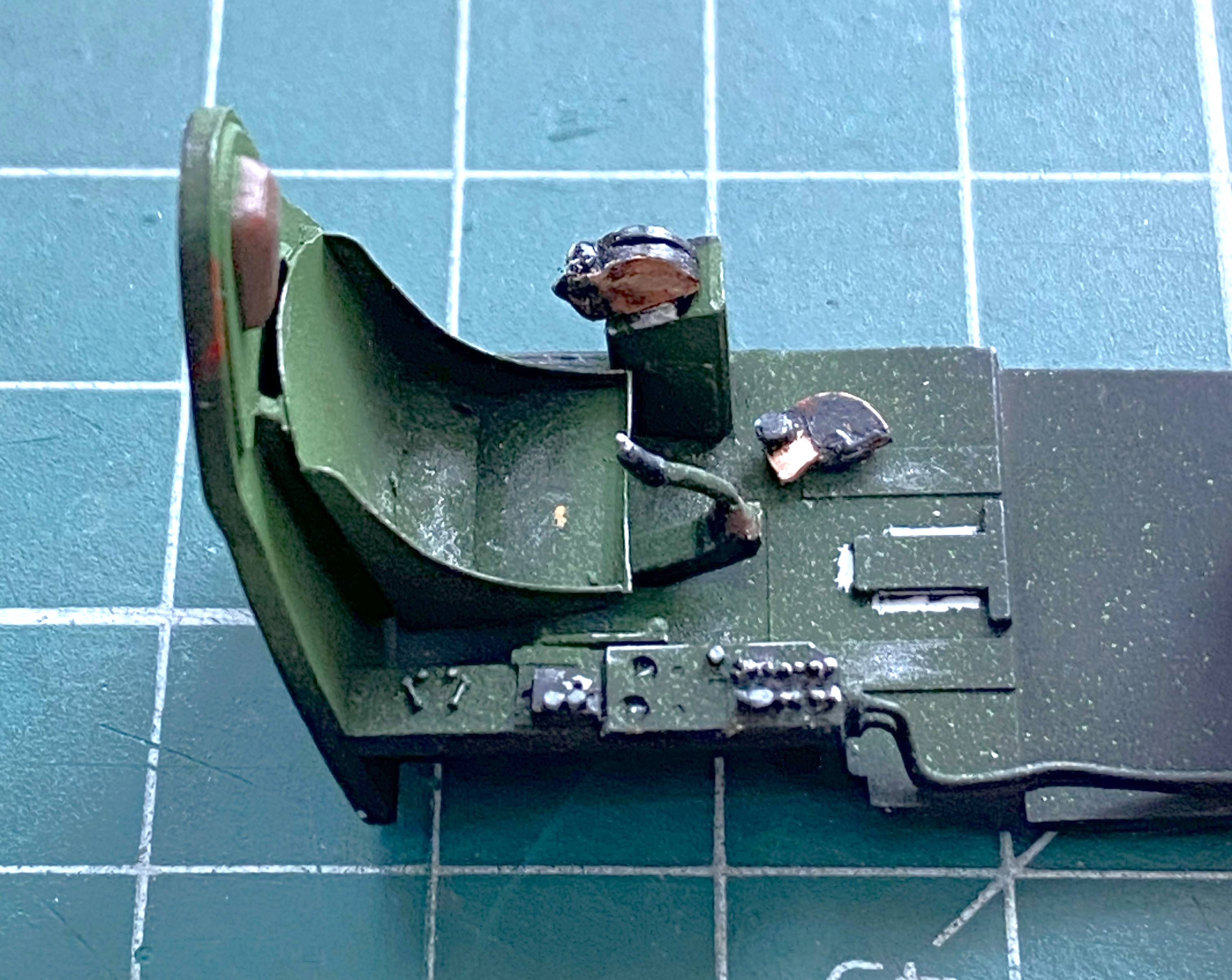
Then I remembered the harness…
I’ve been eager to try the molded styrene AM harnesses. I was pretty sure that bending and folding them to fit would cause them to snap. I used HOT water and took my time heating and bending (and even then almost snapped the shoulder harness’ acute bend over the top of the seat’s back):
The straps were painted a mix of Tamiya’s XF-49 Khaki (3 parts) and XF-64 Red Brown (1 part), the metal bits painted with X-11 Chrome Silver, and the leather pad backing the lap strap buckle was done with XF-64 Red Brown:

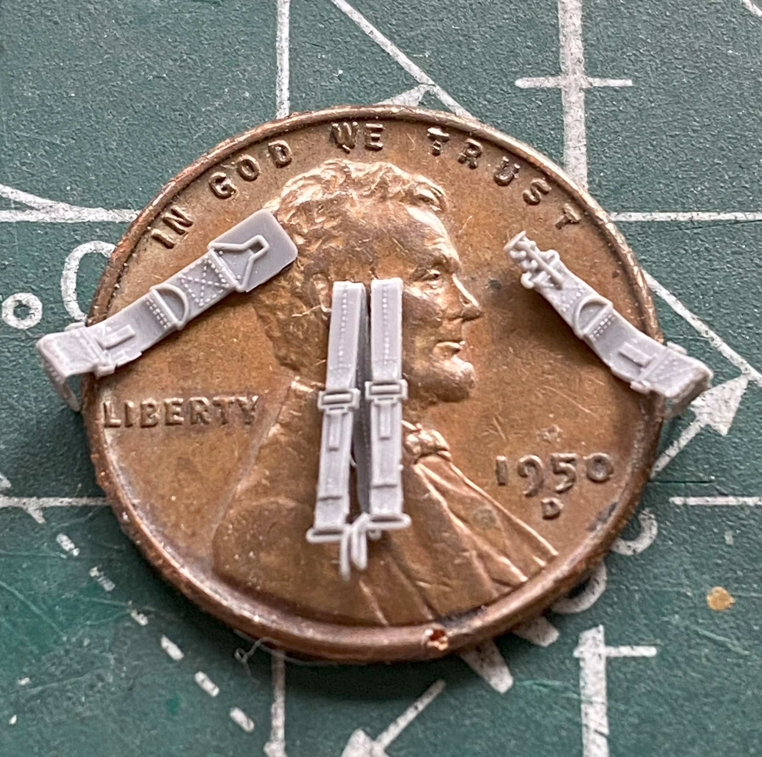
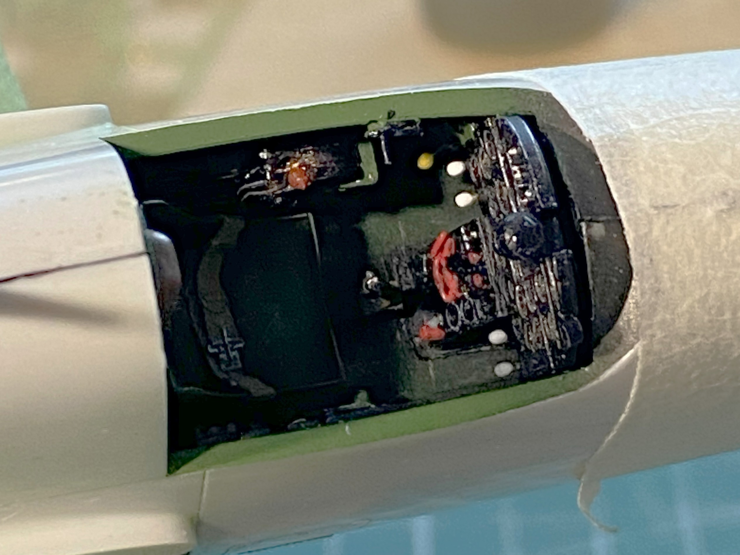
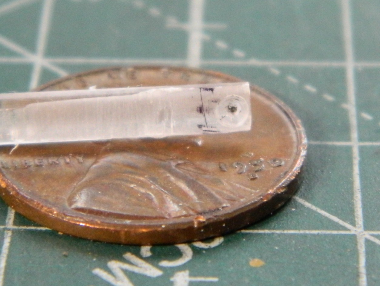
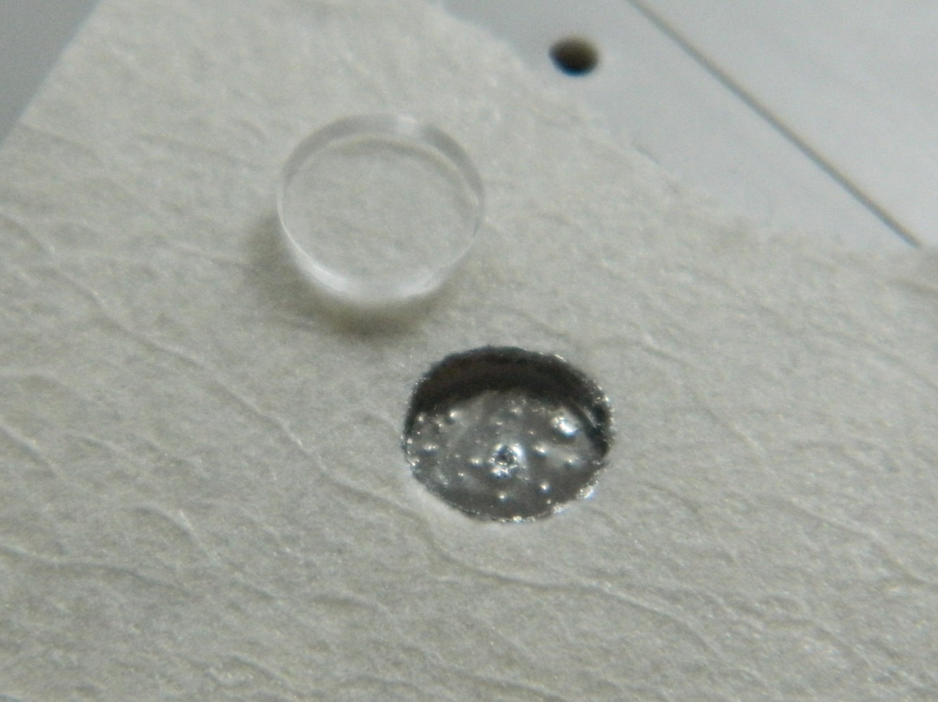
Then it was time to add those tiny control levers to the throttle quadrant. I tried a bunch of things, flattened wire and strips of heavy aluminum foil, none of which worked with a rodent’s rectum. I finally ended up using 0.010″ (.254mm) solder that I flattened out. That worked surprisingly well. Remember those tiny glass balls? Only one was used and none of them for the throttle quadrant control levers. For the latter, I used UV-setting resin, and that worked even better withOUT all the sodding hassle working with tiny balls (no comment, he comments)…and forgot to take pictures. You’ll see later when the instrument panels shows up in a photo because I did the same for the landing gear lever (lower left of the instrument panel with a yellow ball) and gun charging handles (four of them, two on each side at the bottom of the instrument panel with white balls).
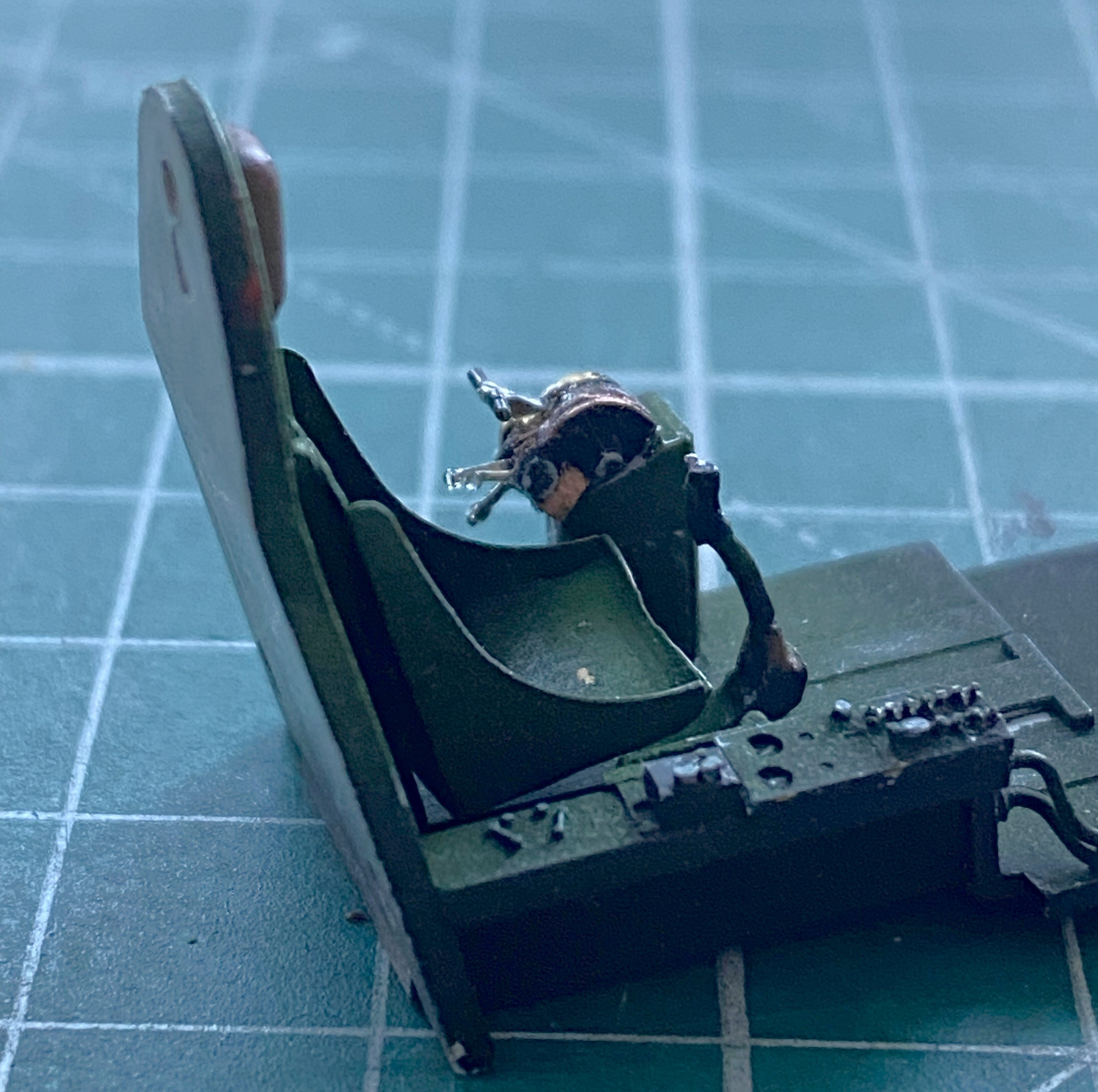
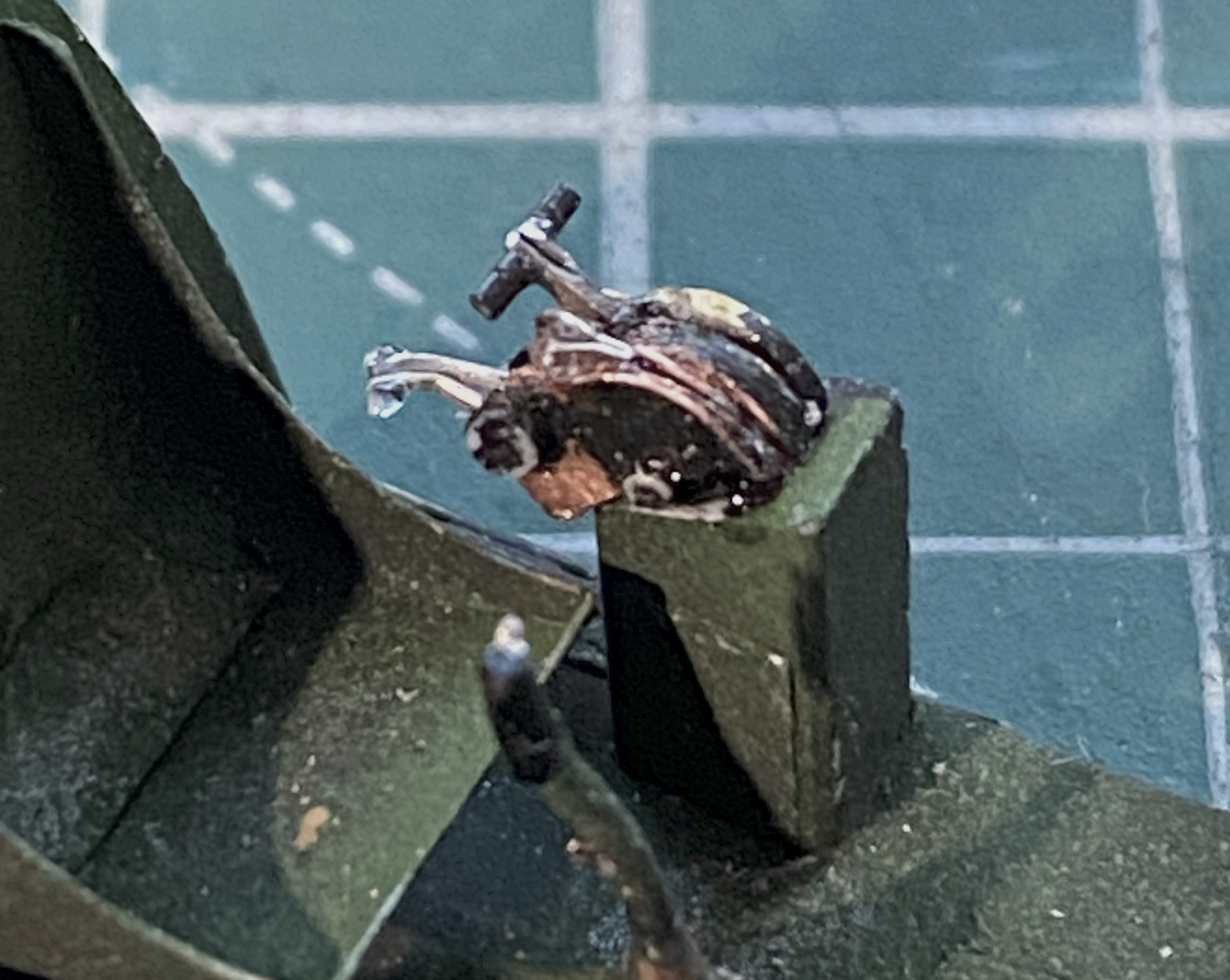
I was pleased with how the parking brake T-handle came out. Then realized what I’d really forgotten to add before painting. The trim controls. All of these bits fit into the cockpit of the actual Tigercat. They don’t all fit into a 1/48 scale model of the Tigercat. And thinking like a pilot, I figured trim controls were of more utility than a parking brake handle (because, chocks are a thing), which meant I had to remove the brake handle. The brake handle that’s already been painted on the cockpit side that’s already been painted. (::facepalm::).
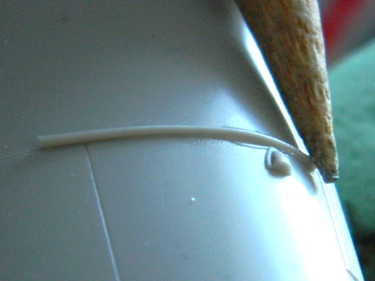
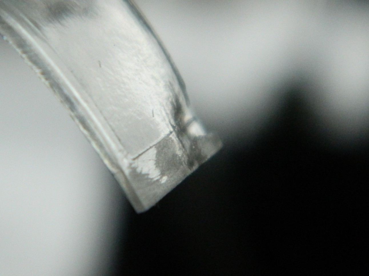
I modified the PE part slightly by removing the flat parts that are supposed to represent cylindrical parts by cutting them off and adding 22 awg wires in their place. The pitch trim wheel isn’t at all flat and the PE’s replacement is. I used the UV-setting resin to build up the flat areas that I want rounded and glued them in place, after removing the parking brake first(sorry about the blurred photo):

Being lazy, I didn’t want to repaint the entire cockpit side, so I made a handheld mask to paint just the areas I needed to (the mask is behind and above the cockpit side, the pointed end of which aligned over the rods):

And then a case of brain-fade struck. The throttle quadrant. Again. Some more. As EVER. One of the slots needed just a little bit of adjustment. Just when I had it where I wanted it, the fornicating front half of it snapped off:
I’m starting to get a depression in my forehead in the shape of the heel of my hand from all the facepalming I’m doing. (I’m already on blood pressure medication so my options for physically manifesting “DOH!” are limited to what I assume I can survive.)
Well, it’s not as if I don’t have practice PUTTING THIS INTERCOURSING THING BACK TOGETHER. Preparing the parts took longer than fixing them. The superglue that had been holding this together didn’t vanish because the parts separated. It’s still there. It also interferes with getting the part reattached. CAREfully removing the old superglue (fresh razor blade, sharpened scalpel) took longer than reattaching the detached part back on. But I won (for now, anyway):
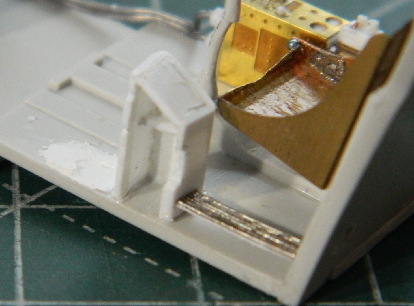
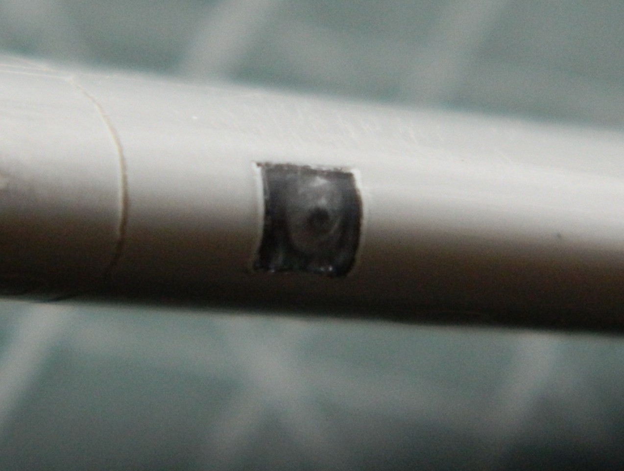
Those two photos show the UV-setting resin’s balls. (Go wherever you like with that one.) Those were attached and got painted the required colors, and dry-fitting looks like the cockpit is ready to install):

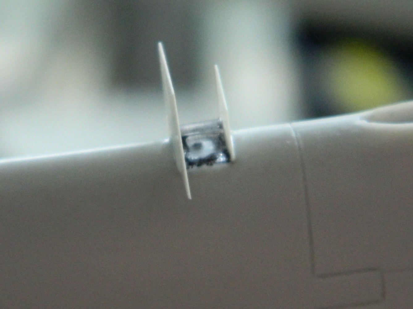
But first, he says smugly because he remembered what he forgot to add to the instrument panel…rudder pedals, I added the rudder pedals. So far, those were the most annoying parts to add because they were as fragile as butterfly wings:
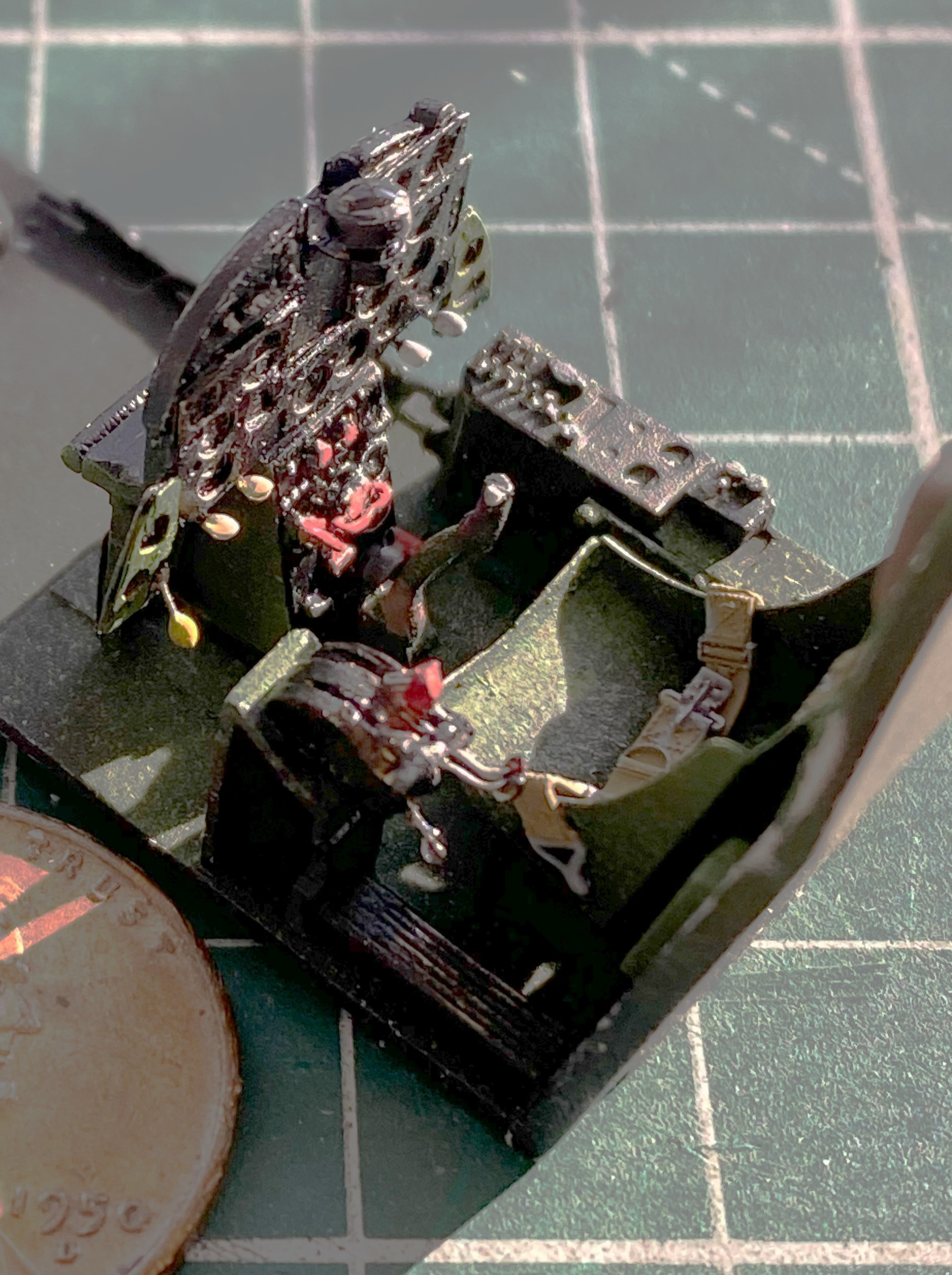
They were added and painted and I went back to putting things together:
One more bit to add, the wiring harness below the switch/control boxes:
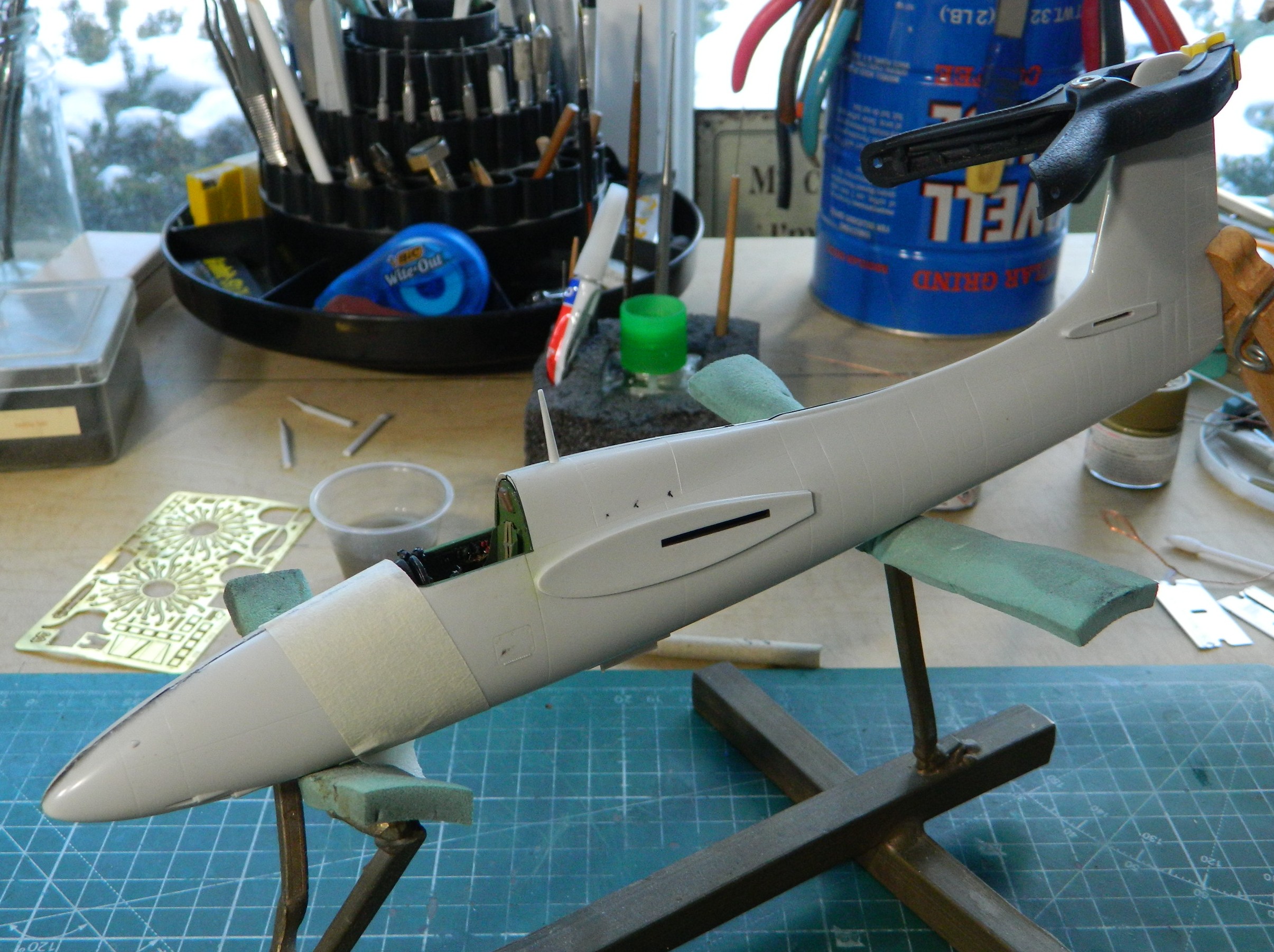
That process wasn’t without its ohgawdammit moments. The fuselage area around the cockpit wouldn’t quite meet. I traced it down to the instrument panel by checking references. The sides of the panel are angled inward. I carefully bent the wings inward, then equally carefully touched up the paint (again) and reattached the fascia of the panel to the film behind it (again). The small bends on either side of the panel allowed the gap to vanish and glue was applied.
Then the two halves were joined:


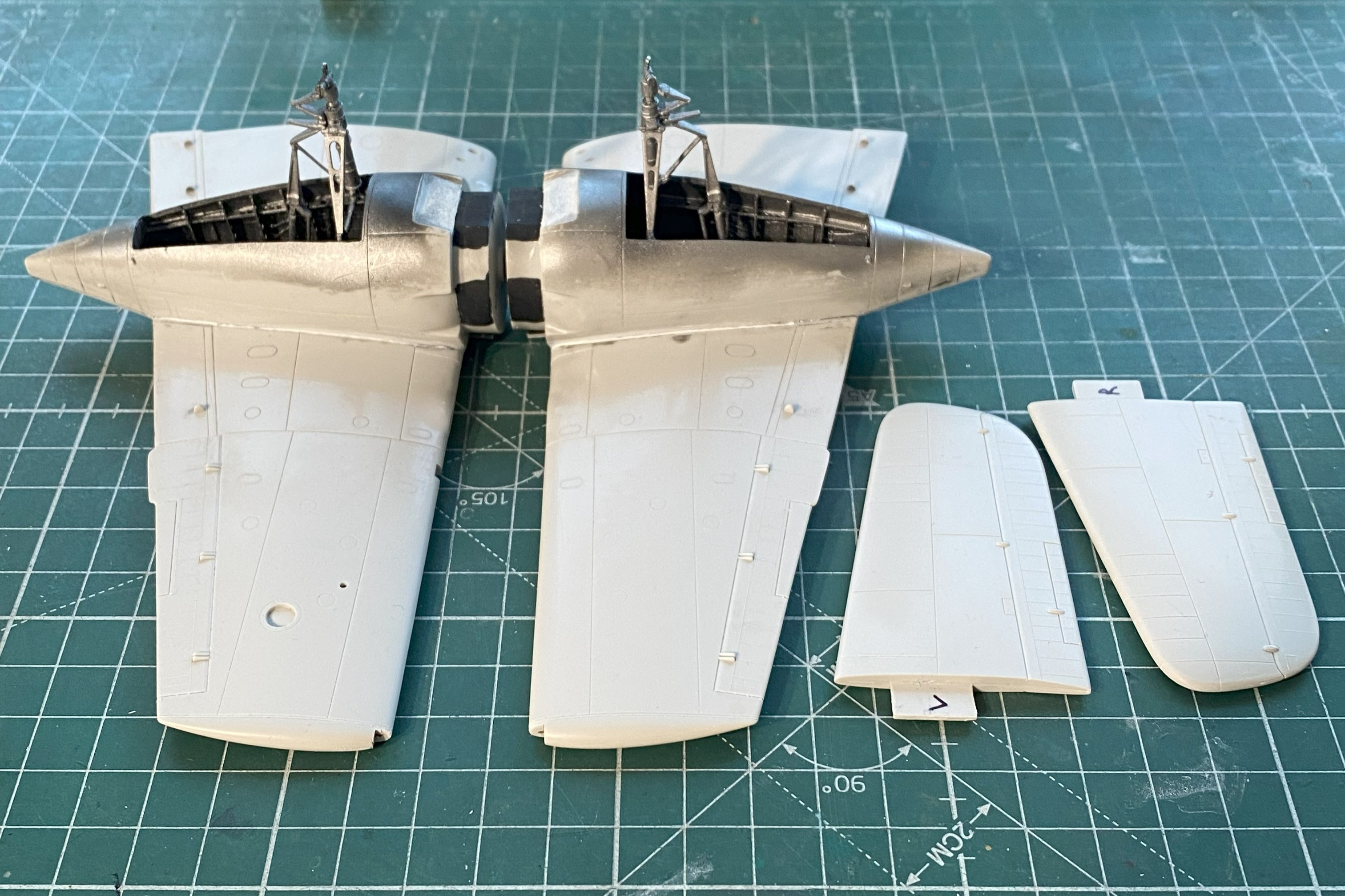
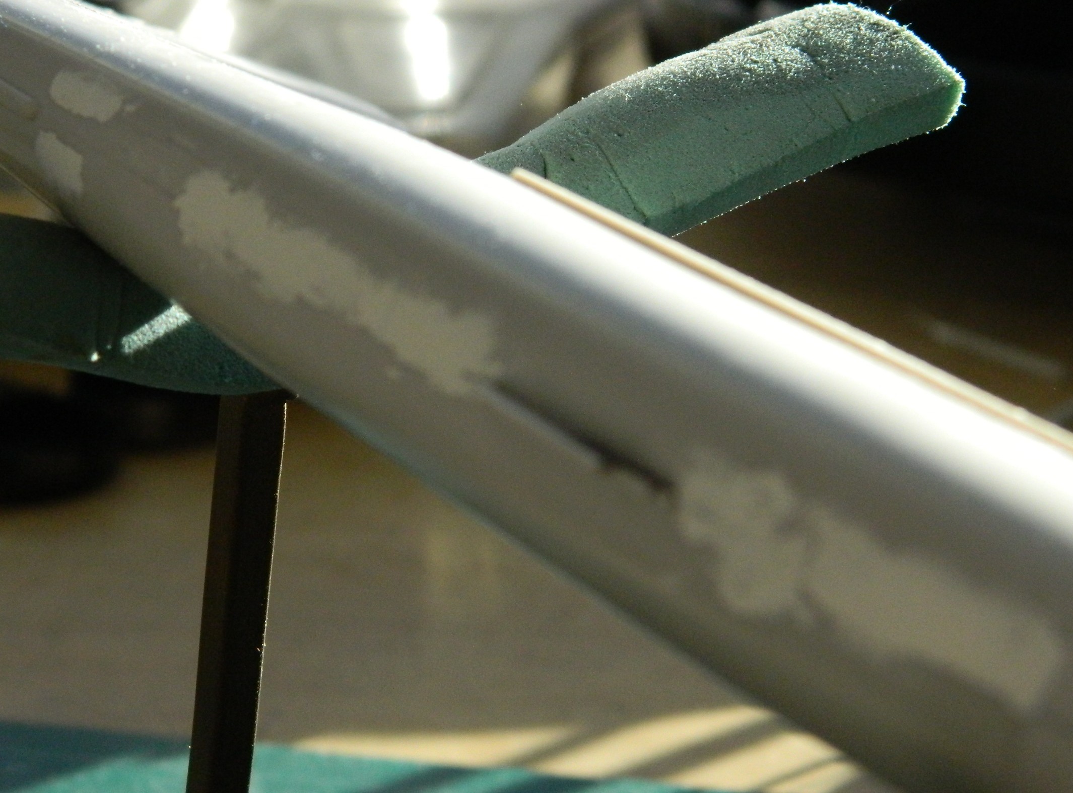
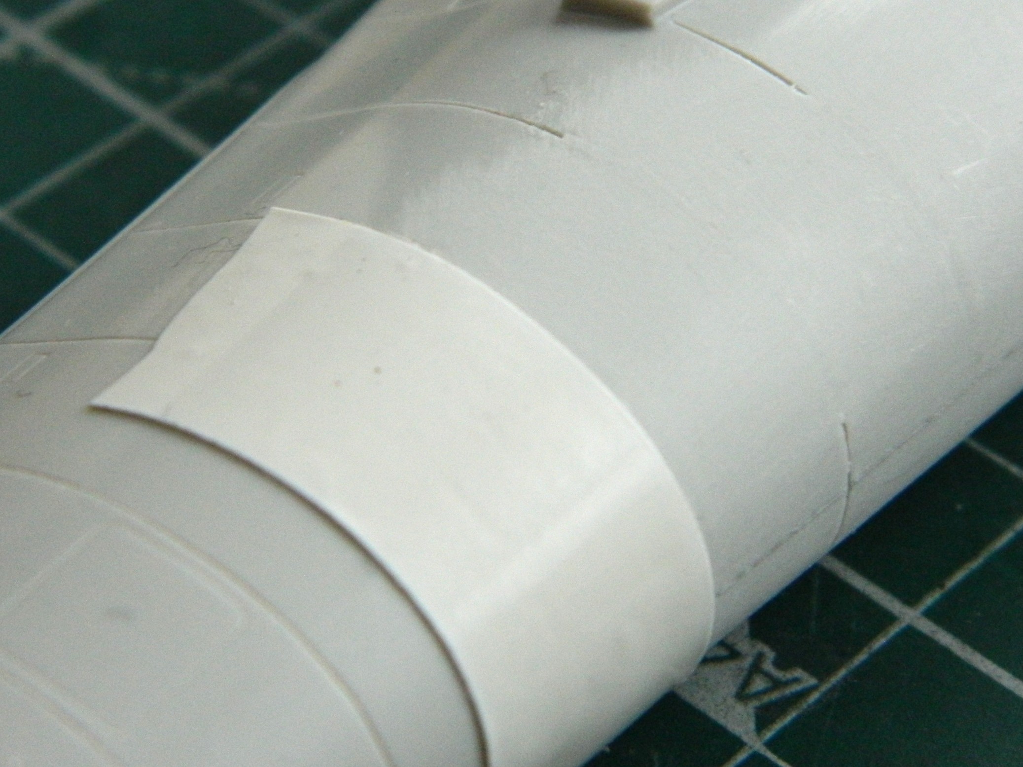
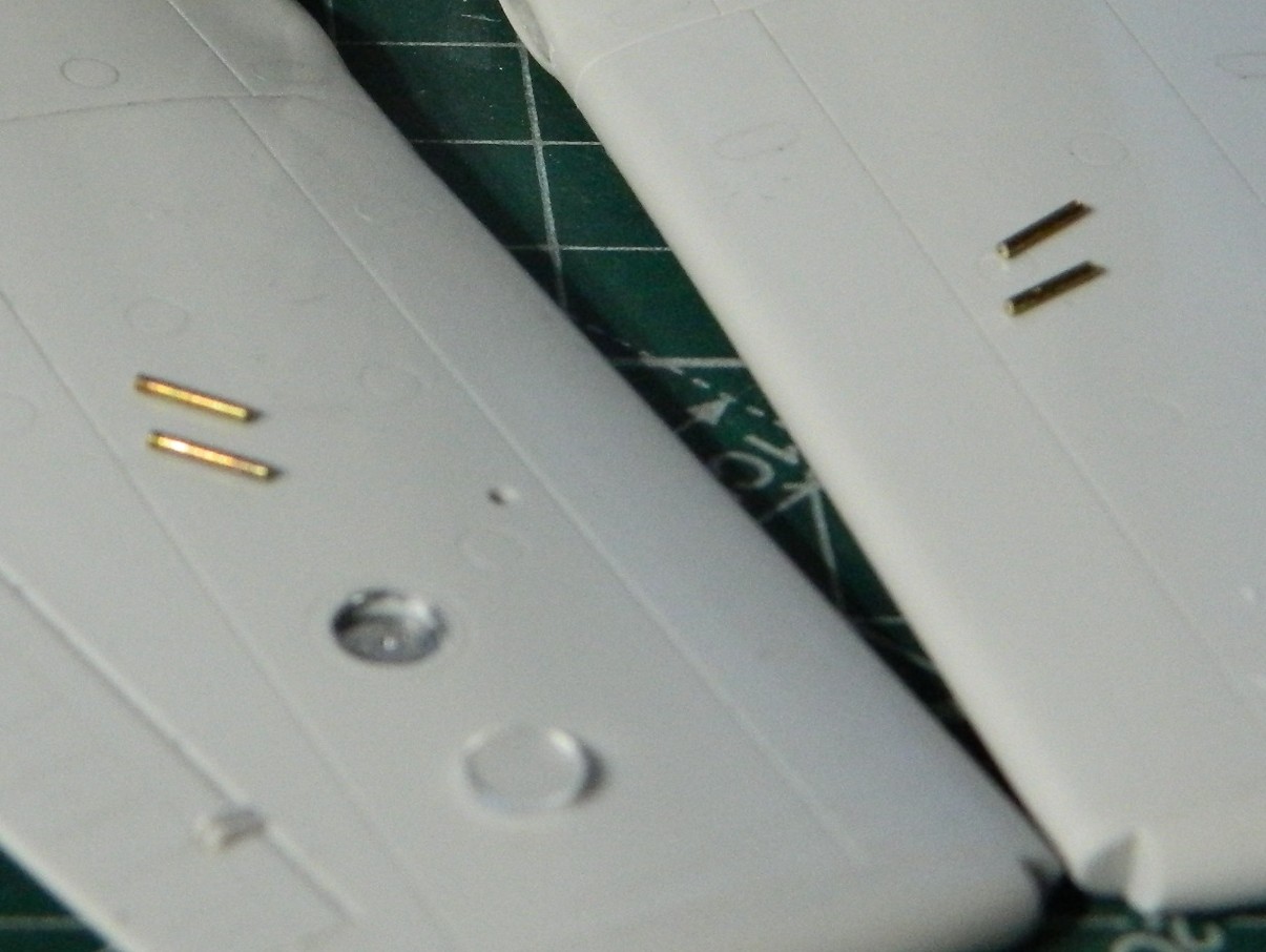
While that was glued and clamped, I started working on the wings and empennage. There are a few lights that needed to be redone. The leading edge of the port wing has a landing light in it as well as underneath the wing, and both wing tips have formation lights. The area of the wingtip lights are molded solid so those were cut out to allow for clear material to be inserted:
Speaking of lights, there’s a row of three lights under the rear fuselage. The were molded as raised “details” and I knew that they’d be sanded off as the less-than-perfect fit between fuselage halves will need a bit of sanding. I had intended on drilling them out and adding clear sprue inserts instead anyway.
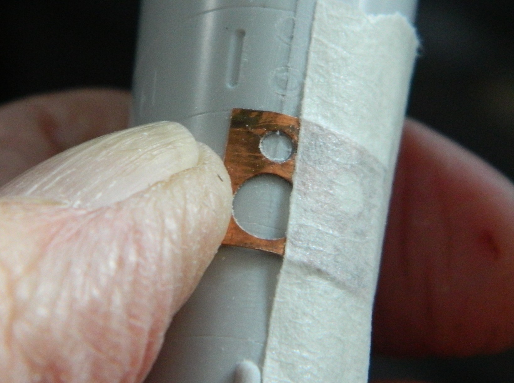
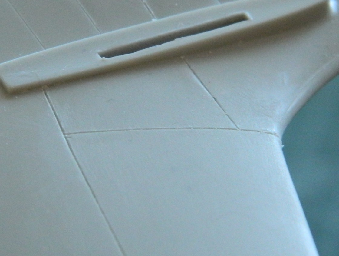
The problem is that I still suck at scribing. Scribing round details would require me to increase my results by a magnitude (at least) to be considered marginal. None of the templates I had offered me the diameter I wanted so I used a punch and die set to punch a correctly sized template from 0.005″ (.127mm) copper shim stock. It worked well enough, particularly since these are just drilling guids:

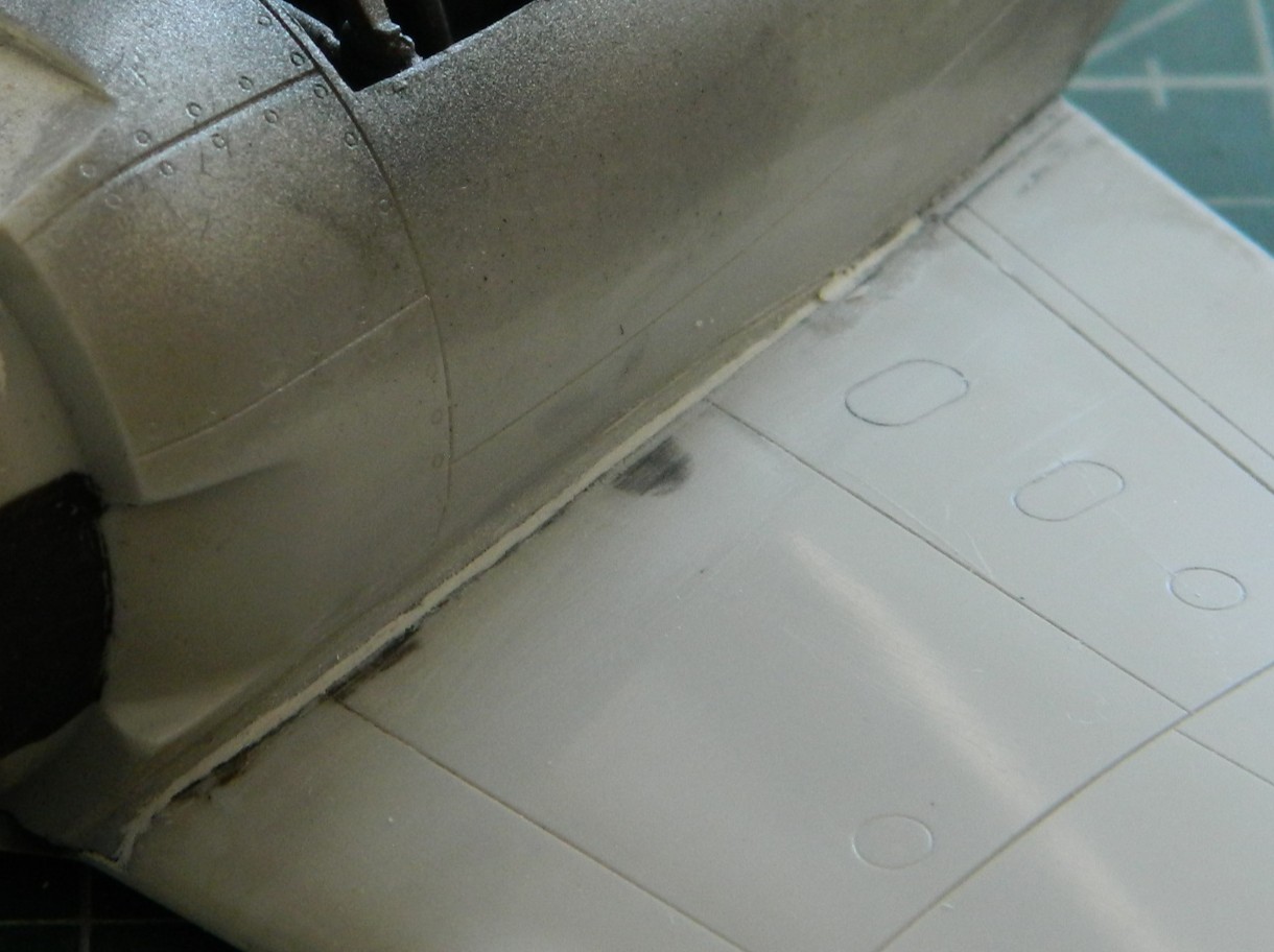
I’m trying to move away from using putty as my default filler, preferring instead to add scrap styrene whenever feasible. Because of adjacent panel lines around and under the nose of the fuselage, sanding to make the surfaces meet would have required a bit of putty. Instead, I added a strip of 0.010″ (.254mm) plastic under the nose for most of the fill with a little bit of putty to smooth the transition into invisibility:
There were other places that needed putty as well and that was applied:
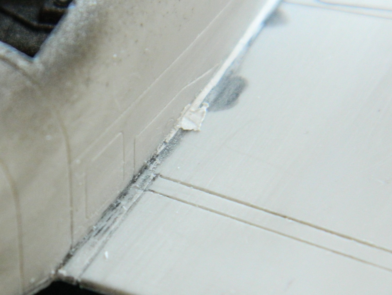
I did mention that I SUCK at panel lines, yeah?:

Once this update is done and posted, I’m going to do a separate tutorial on how to fix errors like the one shown above. If you also SUCK at panel lines, you may find the upcoming tutorial of use.
So I added stretched sprue to fix that one…and all the other ones that I bitched up:


And since I LOVE scribing panel lines, I got to do these twice! How lucky am I… What happened was that I didn’t let these additions cure for two days, only one. When I started hitting these areas with a scriber, adjacent plastic, because it was soaked with Tamiya Extra Thin cement, was also softened. One overnight wait was insufficient for all the cement to utterly evaporate and for the styrene to completely harden. So this was all done again and then sat for two days before I tried working them again. I think that I’ve gotten them as well as I can manage:


Next problem to address is the poor fit between the engine nacelles and the wings. I was undecided as to whether to use putty or add styrene. I tossed a coin and putty won out. I wanted to keep the putty off of surfaces I didn’t want covered in putty. Rather than mask off those areas with masking tape, I ended up using electrical tape instead. Electrical tape will stretch and either conform to curves or outline curves. Try doing this with a paper-based tape:
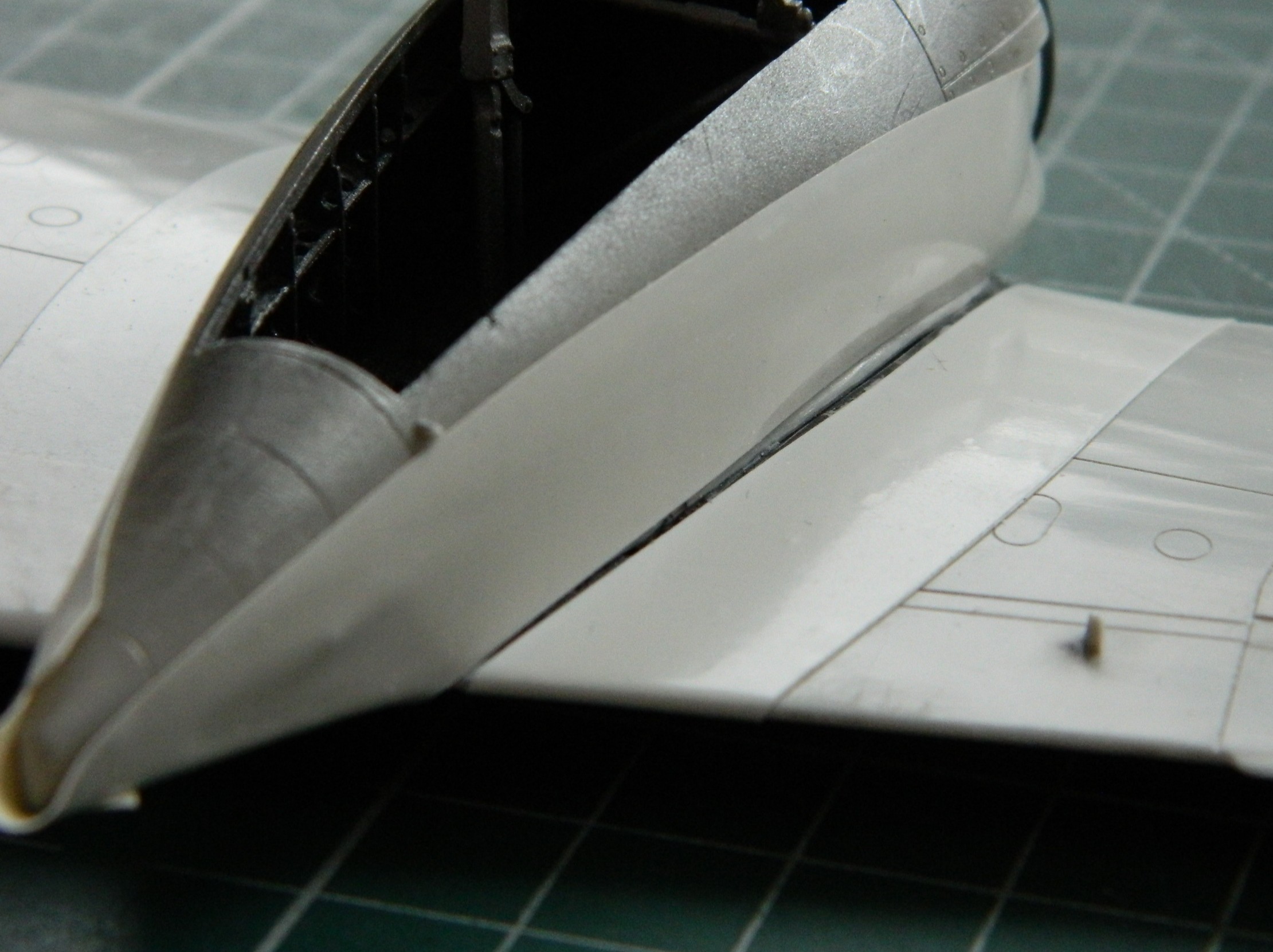
I let these things sit overnight because I wanted the putty as hard as it can be. Then there was a lot of sanding, filing, scraping…more putty to fill areas that I’d missed (or the putty didn’t adhere well enough) followed by scraping, filing, and sanding. Eventually I arrived at the result that I wanted:

Once I hit these areas with gray paint (probably Tamiya’s XF-20 Medium Gray), I’ll be able to see if the curves where nacelles meet wings are evenly shaped.
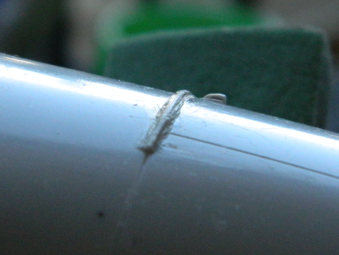
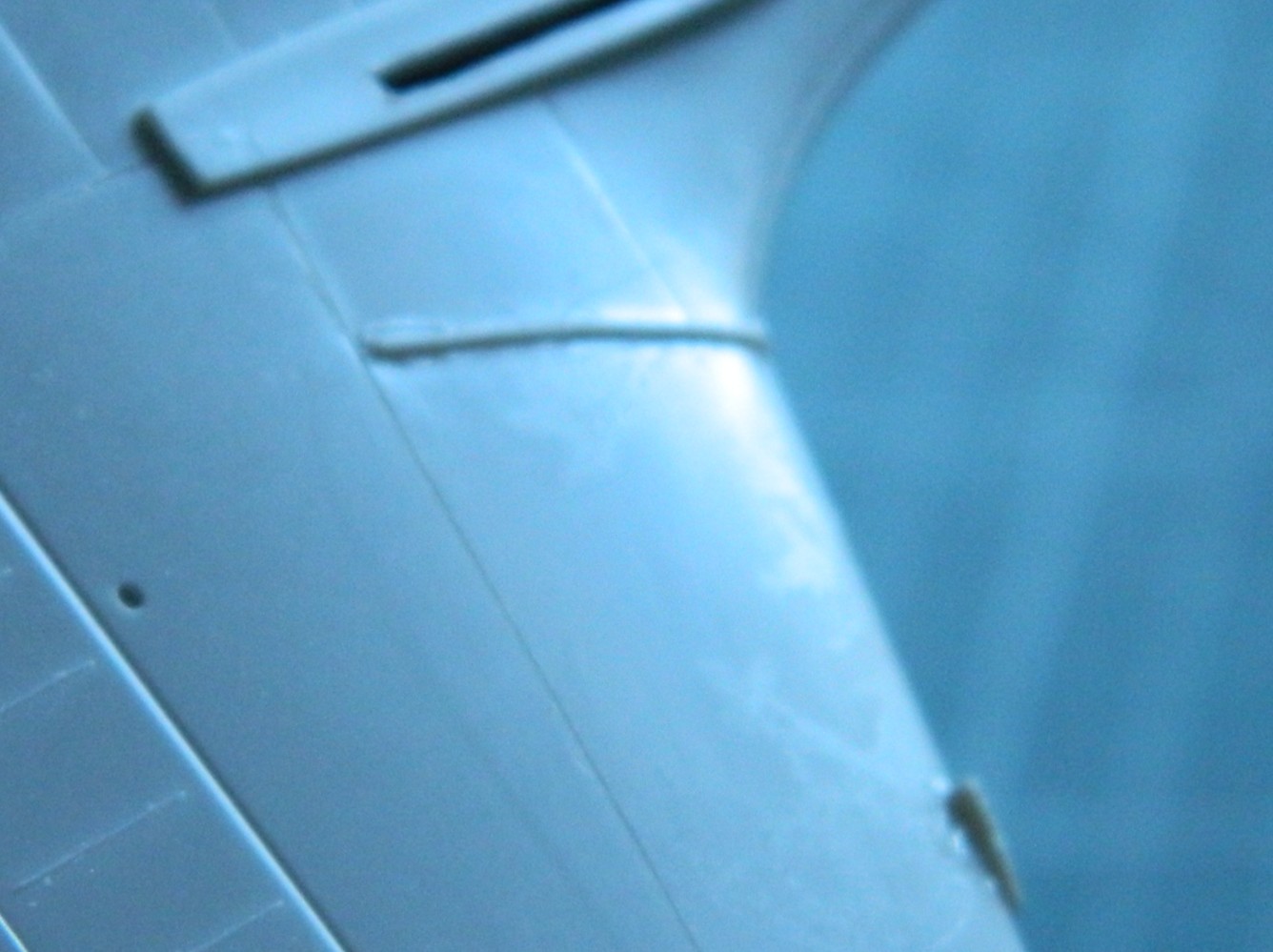
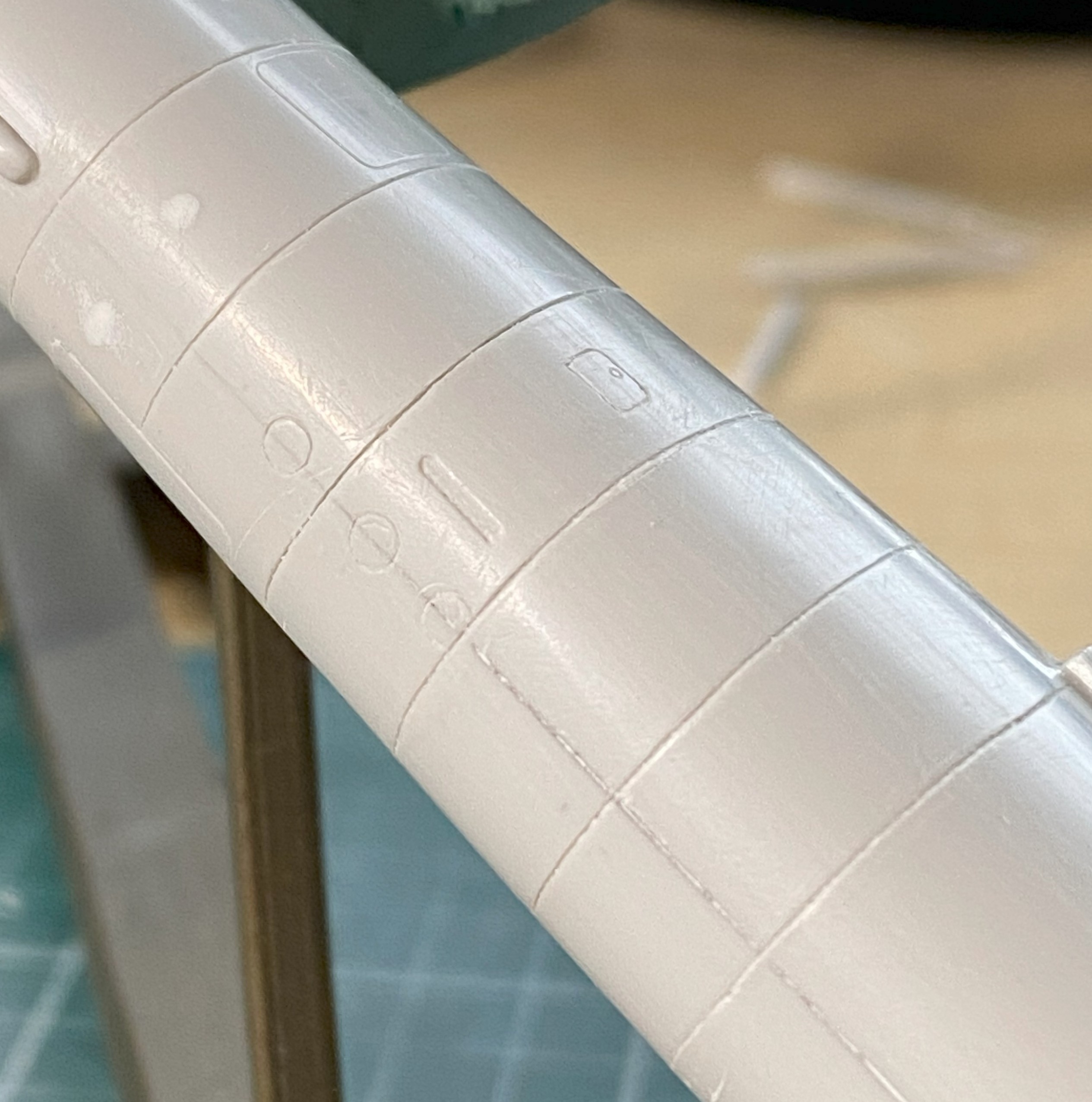
While I was working the wings and empennage, I also fixed misaligned, wrong, or missing panel lines (just because I LOVE do this) (spits). This example is looking down at the top of the wing where the flaps are. The line on the left aligns with the line underneath, unlike the line on the right (and no…I wasn’t satisfied with the line I’d scribed, so I filled it with stretched sprue and redid it):

I persevered and ended up with these (the empennage had the same problems and were fixed the same way):

With the repaired panel lines sanded smooth, scribing happened next. Unable to speak for anyone else (and marginally able to speak for myself), trying to scribe long and straight panel lines is impossible without a guide. Being able to scribe straight lines around a curved and tapered surface is so beyond my skill-set that there aren’t words big enough to describe the mess I can make nor how quickly I can make that mess. Since I have to scribe straight lines and scribe straight lines around a curved and tapered surface, guides aren’t optional. Because things are tapered, I used electrical tape again (for long straight lines, I like Dymo Label Tape…adhesive and thick):
A light touch and many, many, light passes with the scriber is necessary because the thing that makes electrical tape good for jobs like this has an inherent uh-oh factor. The tape is flexible. Push against it too hard with the side of the scriber and the line goes wherever it ass-biting wants to go, regardless of what I want. Light passes. Lots of them:

And no…I wasn’t entirely satisfied with how those lines turned out…so I did it again. I got lucky and the next attempt(s) worked.
I. Suck. At. Scribing.
When I have to scribe, I find that I have to handle the model a lot. Rotating (all three axis), pressure, fumbling, all expose the model to risk. I already broke the handle off the flap actuating lever and had to redo it…then I managed to snap off the gun sight, too:
I got lucky. It only took me a little over an hour of crawling around on my belly with a pair of tweezers and a flashlight (or torch, if you prefer) to find it. I’m glad that I don’t have to make another one!
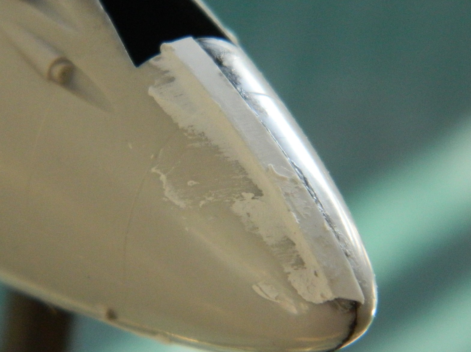
I’ve yet to see a kit that does a good job with landing lights located at the leading edge of a wing. They might be out there, I’ve just never encountered one (1/32 scale, maybe?). This kit isn’t the worst, but it’s certainly neither acceptable nor good. Replacing that requires clear plastic and I just happen to have some. It came with the kit. All I had to do was to shape it and detail it (in reverse order), so I used a vise to hold the stock in place while I filed a flat area that would be deepest in the socket of the wing:
I drilled out what will be taken as the domed section of an incandescent light into the back of the clear plastic. Once done, I used the smallest drill bit I have to make a depression for the “bulb”:
Painting is the opposite of typical. Each layer of paint/color is behind something else. Following that logic trail to its source, the first thing painted is the “bulb”. A touch of black paint. Then the reflector is painted on and for that I used a Molotow Chrome pen. Once it had set up, I gently scraped away whatever chrome was outside the depression and then painted the back of it black.
Then it was a matter of fitting, filing, sanding, and polishing. The “wings” in the photo below are 0.005″ (.127mm) styrene to fill gaps on either side of the insert:
Then it all gets finished (with tape applied to preserve the curvature of the leading edge of the wing):

Not my best effort but certainly good enough (I should have eschewed the drilled “bulb” and used just a needle instead…that’s for the next one I have to do).
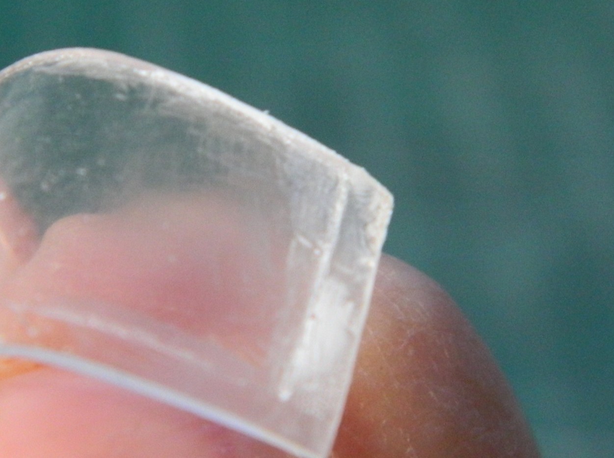
Last update I’d mentioned that the sliding part of the canopy was flawed. Part of it didn’t fill the mold cavity:

Not exactly the end of the world (or build) as I’d not intended on using the kit part in the build. If the canopy is pose open, this part sits far too high to be remotely accurate. My only use for this part is as the buck to vacuform another one over. Since even I know it would be a mistake to try that without fixing the depression, I fixed it. I used the UV-setting resin to build up the missing mass:


That will do.
As an aside, I find that the UV-setting resin is harder than styrene when it’s cured. It also appears to be hard enough to file/sand/polish to clarity. Must remember this the next time I have to repair a canopy that I must use but have just bitched up.
While I was rustling about, I treated the underwing landing light to Molotow Chrome. I used a punch to pop a hole in masking tape, applied it, and didn’t have to worry about slopping the chrome out of the recess:
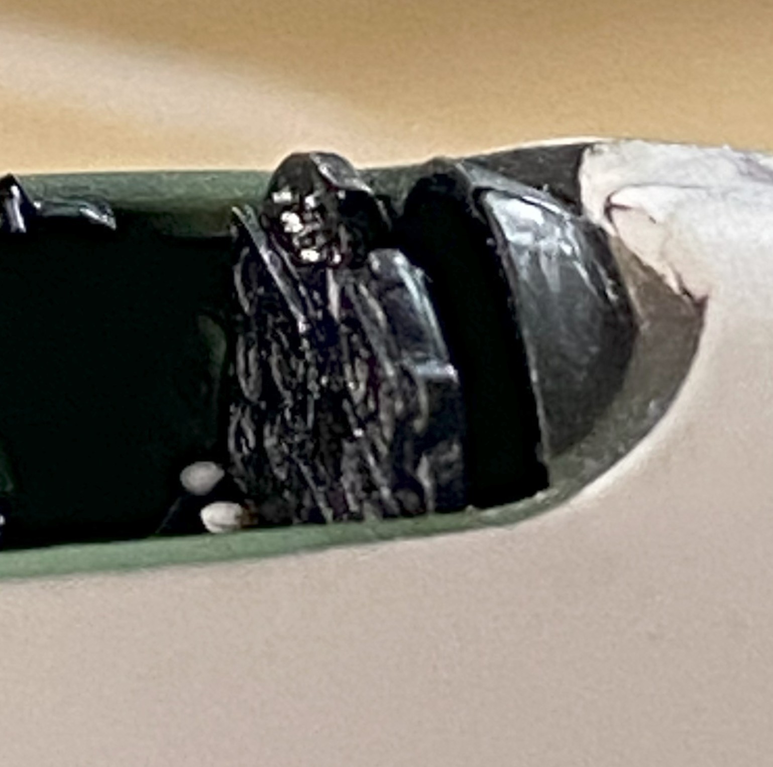
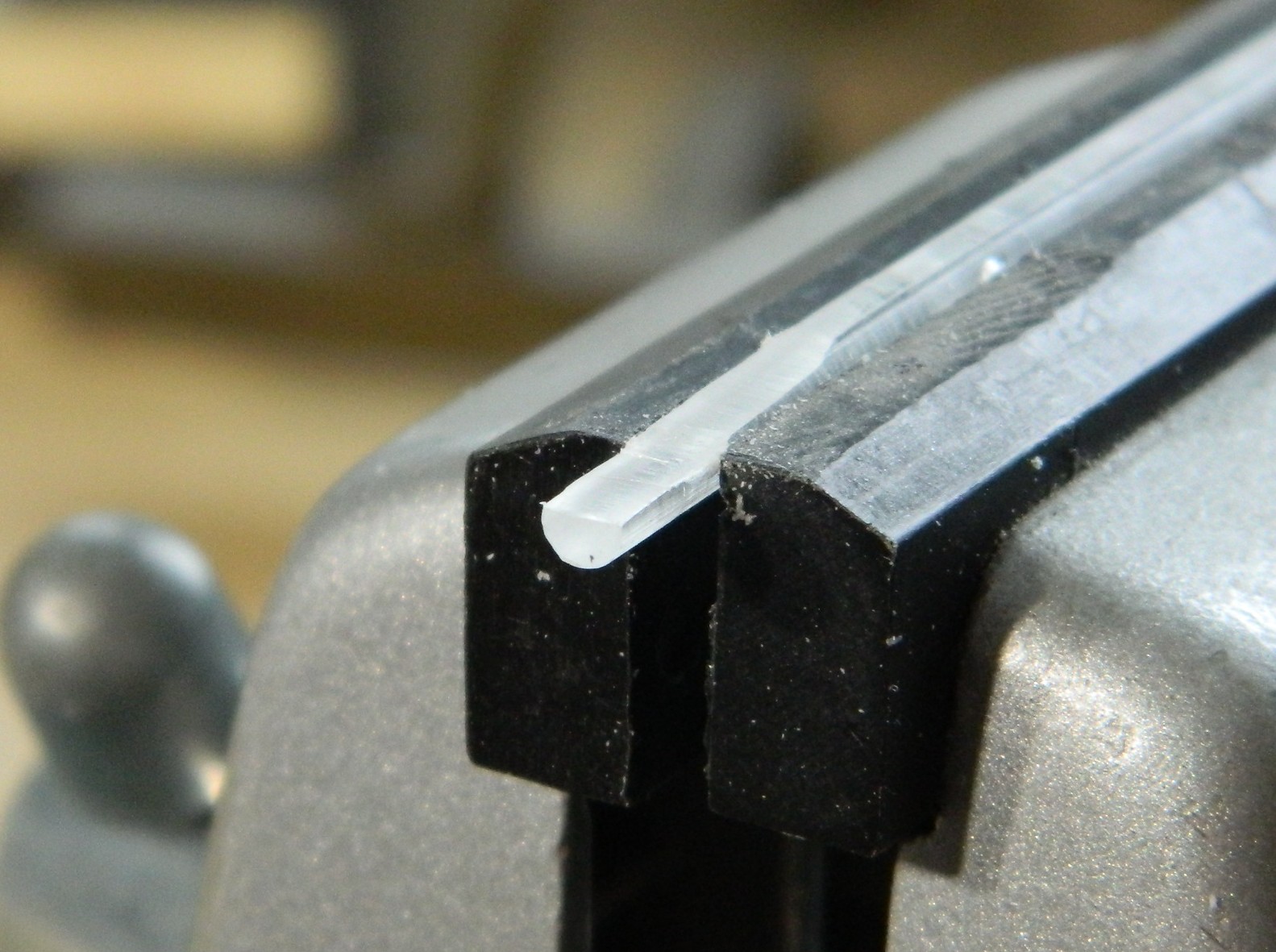
I also used 0.032″ (just under .890mm) copper tubing to replace the kit’s 20mm “cannons”:
I can just see how many times one of those will get knocked off, so I’ll mount them later. I also managed to snap the antenna mast off as well. I’ll add a pin to the bottom of the mast and drill a socket for it to mount to later.
I’m just happy that I do NOT have to work on that sodding throttle quadrant anymore!

Old school scratch building, scribing, and filling…. love it. Solving problems is fun so long as they are discovered early! I chickened out on my Tigercat build so you get double respect from me!
LikeLike
Yeah…this kit isn’t without its challenges. It’s good to see that people who fail engineering school can still find jobs, THAT’S how annoying “fit” is (in quotes because once I see what I have to work with and on, I throw one).
LikeLike
Thanks! What is this “discovered early” or which you speak?! Is this something new? (To anyone other than myself.)
I would chicken out as well but knowing when to quit is still a work-in-progress for me.
LikeLike